Article

On Low-Velocity Impact Response and Compression after Impact of Hybrid Woven Composite Laminates

1
Merchant Marine College, Shanghai Maritime University, Shanghai 201306, China
2
College of Ocean Science and Engineering, Shanghai Maritime University, Shanghai 201306, China
3
State Key Laboratory of Mechanics and Control for Aerospace Structures, Nanjing University of Aeronautics and Astronautics, Nanjing 210016, China
*
Authors to whom correspondence should be addressed.
Coatings 2024, 14(8), 986; https://doi.org/10.3390/coatings14080986
Submission received: 19 June 2024 / Revised: 24 July 2024 / Accepted: 30 July 2024 / Published: 5 August 2024

Abstract

:
This paper aims to study the low-velocity impact (LVI) response and compression after impact (CAI) performance of carbon/aramid hybrid woven composite laminates employed in marine structures subjected to different energy impacts. The study includes a detailed analysis of the typical LVI responses of hybrid woven composite laminates subjected to the impact with three different energies, as well as a comparative analysis of cracks and internal delamination damage within impact craters. Additionally, the influence of different impact energies on the residual compressive strength of hybrid woven composite laminate is investigated through CAI tests and a comparative analysis of internal delamination damage is also conducted. The results indicate that as the impact energy increases, the impact load and CAI strength show a decreasing trend, while impact displacement and impact dent show an increasing trend. The low-velocity impact tests revealed a range of failure modes observed in the hybrid woven composite laminates. Depending on the specific combination of fiber materials and their orientations, the laminates exhibited different failure mechanisms. Buckling failures were observed in the uppermost composite layers of laminates with intermediate modulus systems. In contrast, laminates with higher modulus systems showed early damage in the form of delamination within the top surface layers.

1. Introduction

Composites materials have been widely adopted in industries such as aerospace, marine crafts and trains due to their exceptional strength and stiffness, and light weight properties [1,2]. However, composite materials are vulnerable to impact loads, such as tool drops, collisions with sand, rocks and ice while navigating among islands and icebergs in marine travel and impact from foreign objects during aerospace flight. These impacts can result in decreases in strength and stiffness, as well as the occurrence of matrix cracking, fiber/matrix interfacial debonding and even fiber fracture [3,4].
Low-velocity impact testing (LVI) is a type of mechanical testing that assesses the impact resistance of materials and products. It is carried out by dropping a weight upon the specimen at a predefined velocity. The impact energy is then measured, and the results are used to determine if the material can sustain impact damage [5,6,7,8]. LVI behavior of composite laminates has been extensively studied in recent years. Kodagali et al. [9] examined the behavior of hybrid pseudo-woven meso-architectured carbon/epoxy composite laminates made by automated fiber placement, specifically in terms of their reaction to low-velocity impact and compression-after-impact. The study showed that the meso-architectured laminates had improved impact resistance and compression after impact (CAI) performance compared to conventional laminates. Ma et al. [10] performed a comparative analysis on the low-velocity impact characteristics of unidirectional (UD), woven and hybrid UD/woven fiber-reinforced polymer (FRP) composite laminates. Their findings demonstrated that the hybrid laminates, which combined UD and woven plies, displayed enhanced impact resistance and CAI strength in comparison to laminates made from a single material.
The energy-absorption and load-carrying capacities of composite materials are crucial factors in determining their performance when subjected to impact loads. Zhu et al. [11] examined the behavior of composite laminates after being subjected to high-velocity impact and subsequent compression. The study utilized both experimental and numerical techniques to analyze the load–displacement response and damage progression of the laminates. Kumar et al. [12] conducted a comparison between two progressive damage models to predict the behavior of woven composites under low-velocity impact. The study sought to improve the precision of impact simulations and highlighted the need of choosing suitable damage models to ensure dependable forecasts. Zhao et al. [13] introduced a multiscale modeling framework for forecasting the behaviors of plain-woven carbon fiber reinforced polymer (CFRP) composites under low-velocity impact and compression-after-impact conditions. Their methodology incorporated the properties of materials at a small scale and the response of structures at a larger scale, yielding valuable understanding of how composites fail and deform.
Hybrid composite laminates, combining different fiber materials or architectures, have gained attention for their improved impact resistance. Melaibari et al. [14] explored the use of a sandwich composite laminate with an intraply hybrid woven CFRP/Dyneema core for enhanced impact damage resistance and tolerance. The study demonstrated that the hybrid core design effectively mitigated impact-induced damage and improved the overall structural performance of the laminates. Ni et al. [15] evaluated the low-velocity impact and post-impact compression properties of carbon/glass hybrid yacht composite materials. The study investigated the impact response and residual strength of hybrid laminates, highlighting their potential for marine applications.
The CAI test is employed to ascertain the compressive residual strength of a laminate material after impact-induced damage [16]. The specimen, composed of a multidirectional laminate, is initially subjected to pre-damage using an impact energy defined in the corresponding test standard. The damage resistance of a fiber composite laminate to potential impact damage can be assessed by conducting impact testing and determining the compressive residual strength by subsequent static compression testing. Composite structures in aviation can sustain impact damage from various sources. Damage on the impact side is frequently challenging to identify, leading to its designation as “barely visible impact damage.” However, substantial damage, including large matrix cracks and delamination, can occur inside the laminate and on the opposite side.
Yin and Iannucci [17] performed an experimental and finite element analysis to study the behavior of biaxial carbon fiber non-crimp-fabric (NCF) composites under CAI. The authors sought to comprehend the reaction and failure processes of these composites when subjected to compression stresses after an impact event. The researchers conducted both empirical experiments and finite element simulations to examine the behavior of CAI. The results yielded significant insights into the initiation, development and residual strength of damage in the composites made from NCF materials. Anuse et al. [18] conducted a study on the examination of compressing carbon fiber reinforced composite laminates following impact, specifically focusing on laminates with varying ply orientation sequences. The authors conducted a study to examine how different ply orientation sequences impact the CAI behavior of laminates. The researchers performed experimental experiments and numerical simulations to assess the behavior of the laminates when subjected to compressive pressures following an impact. The study offered valuable insights into how the orientation of ply affects the strength after impact, the mechanisms of damage and the modes of failure in laminates made of carbon fiber composites. Zhou et al. [19] investigated the dynamic mechanical response and damage mechanism of composite laminates under single and repeated LVI. Lei et al. [20] studied the low-velocity impact and compression-after-impact behaviors of twill woven carbon fiber/glass fiber hybrid composite laminates.
However, there are few studies on impact resistance and residual strength of carbon/aramid hybrid laminates with good impact resistance at present. This study aims to investigate the LVI behavior and subsequent compression behavior of the hybrid woven composite laminates after low-velocity impacts employed in marine structures. The study involves conducting the impacts with varying energy levels, to examine how the impact energy level influences the subsequent impact behavior. Compressive strength tests of all specimens are then performed to analyze the effect of the impact on CAI strength. The impact resistance and residual compression properties of hybrid woven composites for marine structures are studied. Additionally, C-scanning is utilized to evaluate the extent of damage to provide a comprehensive understanding of the evolution of low-velocity impact damage and CAI damage.

2. Materials and Experiments

2.1. Hybrid Woven Composite Laminates

The hybrid woven composite laminates utilized in this study were created with carbon fiber (T300-3K, TORAY Inc., Japan) and aramid fiber (Kevlar®29, DuPont Inc., USA), chosen for their exceptional mechanical properties and impact resistance. The combination of these materials with an epoxy resin (E51, Brand 618, Nantong Xingchen Synthetic Material Co., Ltd., China) system is essential for effectively binding the fibers together and strengthening the overall structural integrity of the laminates under the hot pressing process. Composite laminates with the lay-up sequence as (0, 90)12 were made of carbon/aramid fabric prepreg by hot the pressing method. Each laminate consisted of 12 layers with an average size of 150 mm × 100 mm × 3.4 mm. For layup (0, 90)12, this configuration implies that in each layer, carbon fibers are oriented in the 0° direction and aramid fibers are oriented in the 90° direction.

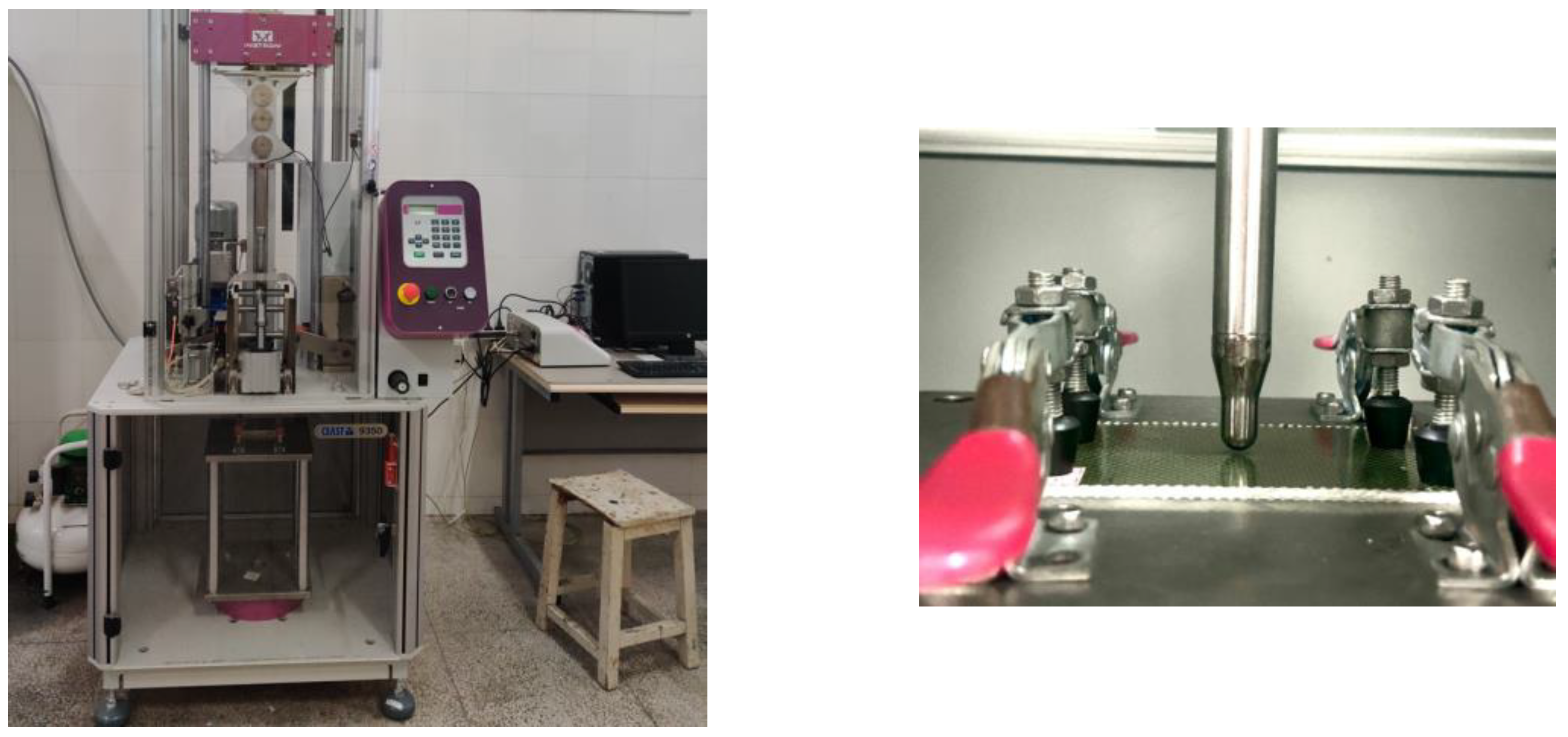
2.2. Low-Velocity Impact (LVI) Tests

The LVI tests were performed on an Instron CEAST 9350 drop-weight impact machine according to the ASTM D7136 standard [21], as shown in Figure 1. The machine was outfitted with a 12.7 mm diameter hemispherical impactor. The impact energies were configured to 10 J, 20 J and 30 J, which reflect distinct energy levels that mimic plausible real-world impacts. Every specimen underwent three consecutive impacts at each energy level to evaluate its consistency and repeatability. A high-speed data-acquisition system was used to record data on contact force, absorbed energy and deflection.

2.3. Compression after Impact (CAI) Tests
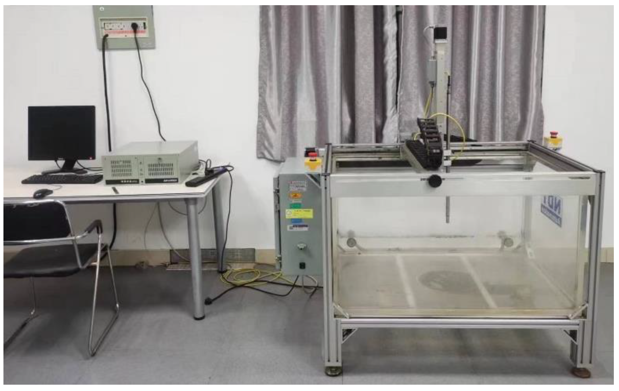
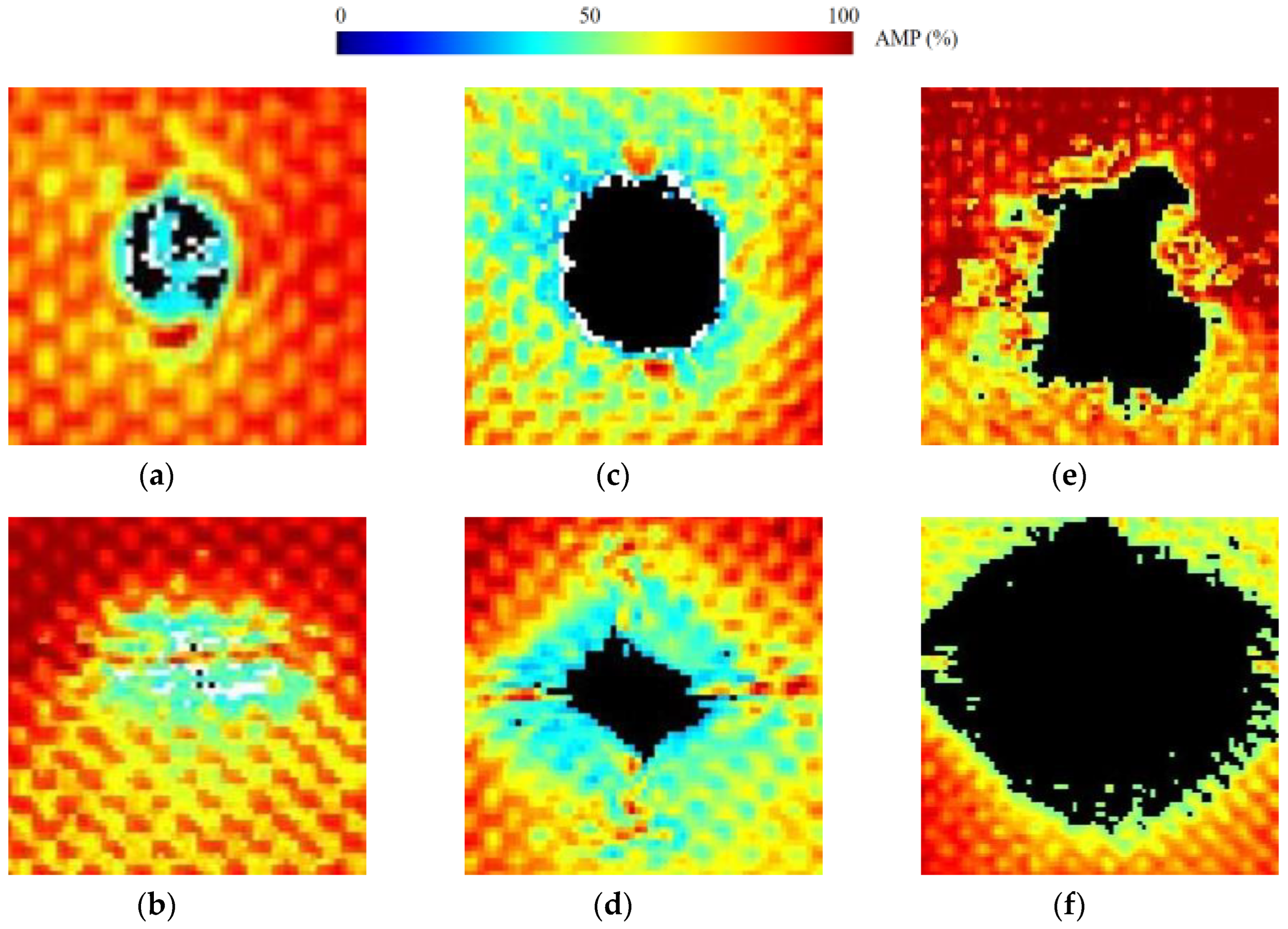
According to the ASTM D7137 standard [22], the CAI tests were performed on impacted specimens to evaluate the residual compressive strength of composite laminates after impact, as shown in Figure 2. The CAI tests were conducted using an Instron 5982 universal testing machine. The specimens were positioned within a compression fixture to guarantee accurate alignment and reduce bending to a minimum. The experiment utilized a compressive force at a consistent rate of 1.25 mm/min until the point of failure. The residual compressive strength was determined, and the failure modes were recorded by conducting visual inspection and C-scanning analysis. This testing method is utilized to assess the compressive performance of composite laminate after impact and to provide post-impact information regarding their residual compressive strength.

2.4. C-Scanning

Ultrasonic C-scanning was employed to characterize the internal damage state of the composite laminates after impact tests. The UltraPACTM immersion C-scan device BSN-C1285 automated ultrasonic immersion imaging detection system shown in Figure 3 was utilized for scanning the specimens.

3. Results and Discussion

3.1. LVI Test Results

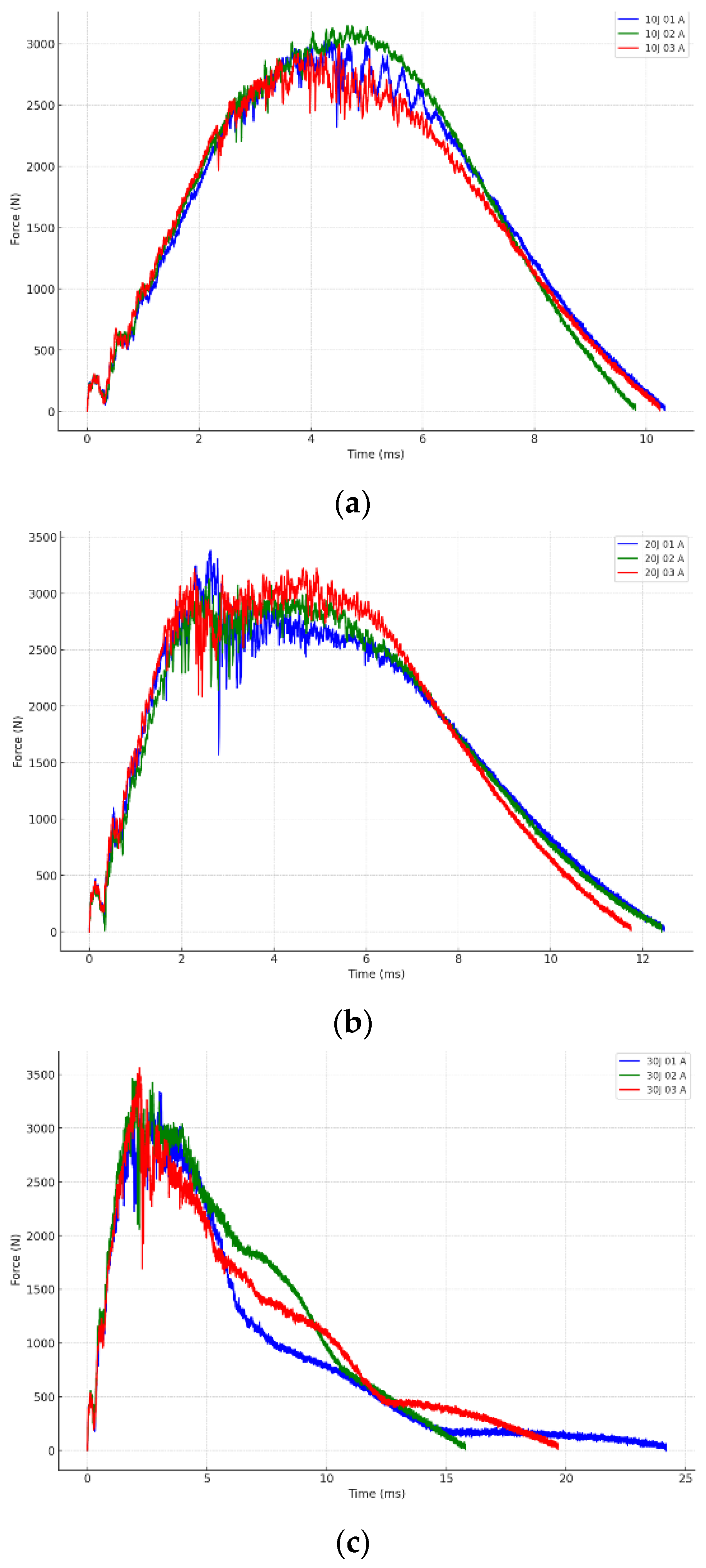
3.1.1. Impact Force–Time Response

Figure 4 shows the first and second impact curves of the 10J-A~30J-A groups. It is seen that the second impact curves of the 10J-A~30J-A groups show no significant oscillation in the initial stage. The oscillation phenomenon occurs only in the middle part of the impact process, and the degrees of oscillation become more pronounced with an increase in the energy of the first impact. The oscillations observed in Figure 4a and the initial stage of the first impact–time curve shown in Figure 4b,c indicate the occurrence of damage and its propagation. One may conclude that the larger the impact energy of the first impact, the earlier the impact damage occurs in the composite laminate. And the curves exhibit noticeable oscillations while the energies of the first impact are higher and reach the threshold for generating greater damage. Notably, these oscillations become more pronounced as the impact energy increases.
The graph depicted in Figure 4a for the 10 J impact test shows a sharp increase in force, reaching a maximum of around 3000 N at around 4 milliseconds. After reaching its highest point, there is a gradual decrease in value, returning close to zero by 10 milliseconds. The uniformity of the response observed in all three tests (01 A, 02 A, 03 A) indicates that the material exhibits consistent behavior when subjected to this specific level of impact energy.
In Figure 4b, the force increases quickly but reaches its highest point significantly later than in the 10 J test, at around 5 milliseconds, with a peak force slightly over 3000 N. The decrease from the highest point is less consistent in comparison to the 10 J test, and the force decreases at a slower rate, with notable fluctuations between tests, especially around 6 to 8 milliseconds. The increased variability seen in the experiments may suggest varying levels of material response or damage at this elevated energy level.
Figure 4c demonstrates a longer duration of increase in force, reaching its highest point at around 3 milliseconds. The force increases quickly to 3500 N. Nevertheless, the decrease from the highest point is characterized by irregular fluctuations and persists for a longer duration, only reaching zero after around 25 milliseconds. This graph clearly illustrates the notable disparities among individual experiments, indicating that higher impact energy is causing more prominent or distinct damage mechanisms within the material.
With the increase in impact energy, the peak force increases and the time to reach the peak force decreases. Various data indicate that whereas the initial material reaction in terms of maximum force capacity is consistent throughout various energy levels, impacts with higher energy levels lead to greater unpredictability and less predictable behavior after reaching the peak. This may suggest the activation of more substantial or distinct damage mechanisms at higher energies, such as matrix cracking, delamination or fiber breakage.

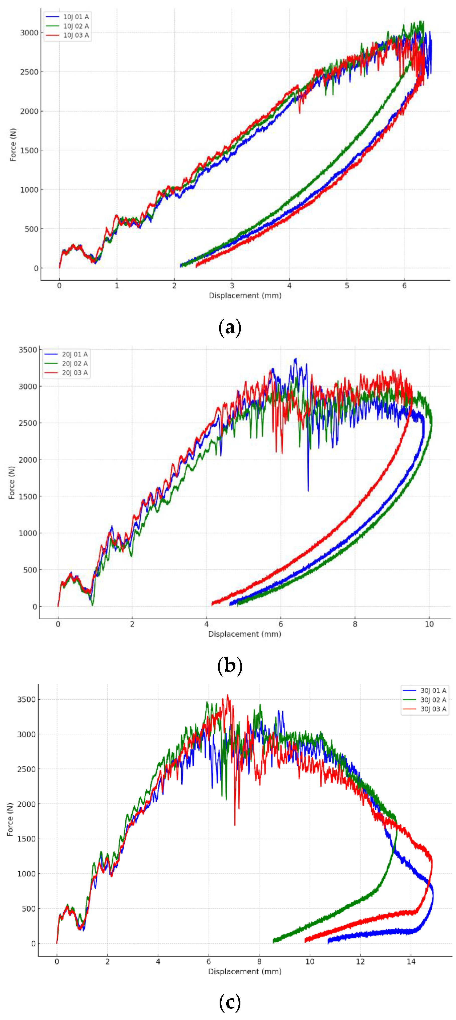
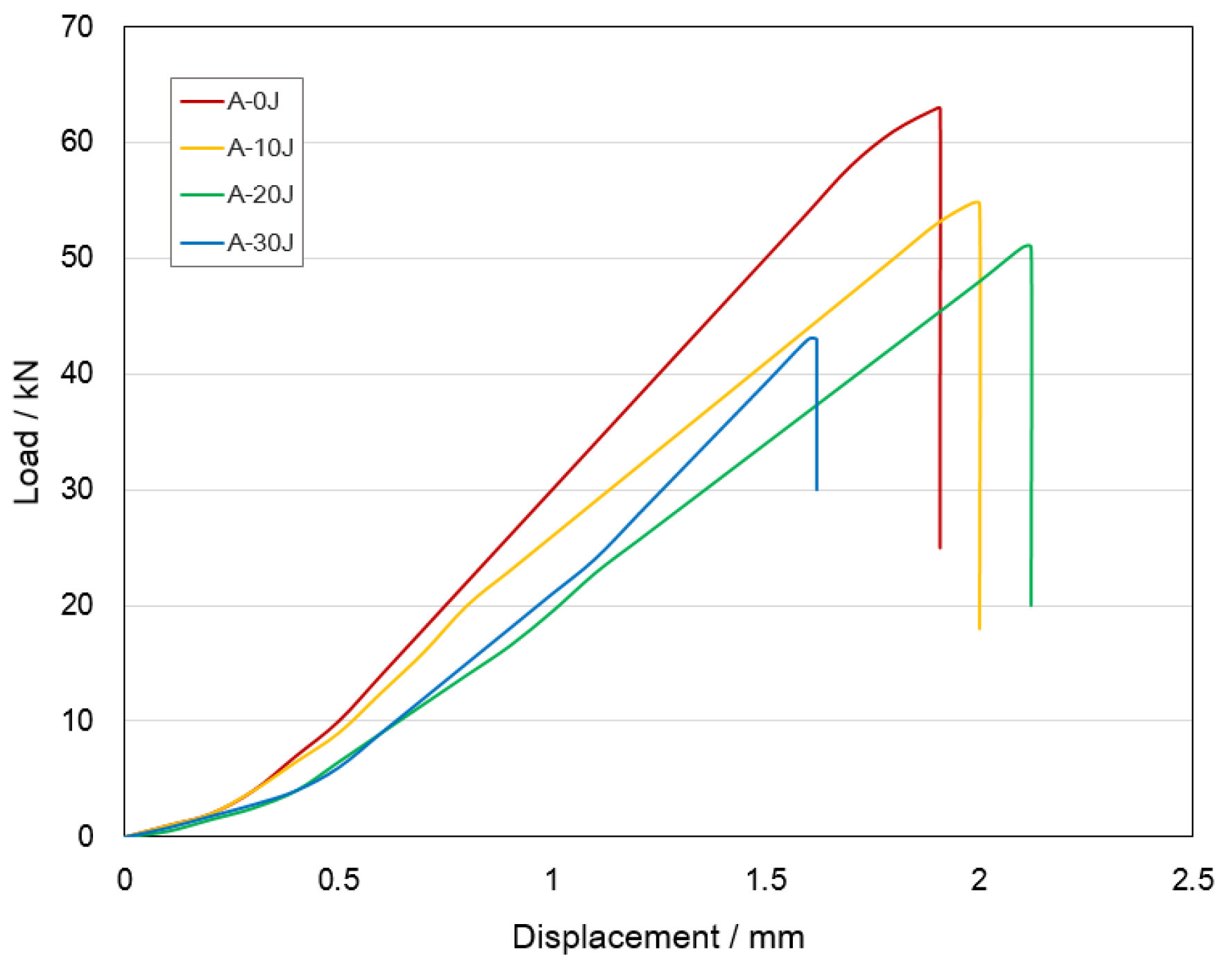
3.1.2. Impact Force–Displacement Response

The force–displacement graphs for hybrid woven composite laminates affected at 10 J, 20 J and 30 J demonstrate how the material behaves as the impact energy increases, as shown in Figure 5. Each graph explains how various materials absorb and respond to shocks by changing mechanical qualities including stiffness, resilience and ultimate failure.
In Figure 5a, the material shows a constant initial increase in force with displacement, which remains linear until around 2 mm. The force peaks near 3000 N at approximately 6 mm of displacement, suggesting high material stiffness and strength at this level of impact energy. Beyond this peak, the force varies somewhat but remains high, indicating that the material does not undergo substantial structural collapse and can withstand small damage without losing integrity.
Figure 5b for the 20 J hit demonstrates a more rapid increase in force, reaching a similar peak force faster than the 10 J impact. However, the graph shows considerable variety across the samples after the peak, with some displaying sharp reductions in force. At this greater energy level, the material begins to lose structural integrity, resulting in increasing damage such as matrix cracking and delamination. The decrease in force at higher displacements, particularly in one sample, shows serious degradation or partial breakdown of the material under these conditions.
In Figure 5c, the material responds even more dramatically, with an initial abrupt increase in force followed by significant fluctuation. The peak force achieved is comparable to lower energy impacts, but it is followed by a sharp decrease in force across all samples, indicating major structural failures. The extreme drop-offs in force, particularly in two of the samples, indicate complete material failure or through-thickness penetrations, rendering the material incapable of resisting additional deformation effectively.
The force–displacement graphs show that with the increase in impact energy, the displacement of the impactor increases gradually. The hybrid laminates exhibit different load–displacement responses under different energy impacts.

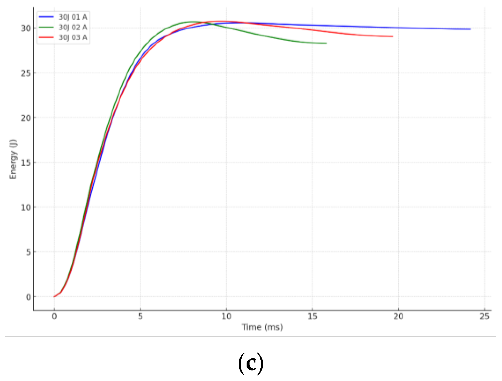
3.1.3. Energy–Time Response

The energy versus time graphs for hits at 10 J, 20 J and 30 J show how the absorbed energy in the composite laminates evolves over time during an impact event, providing a clear picture of the materials’ energy-absorption properties at various energy levels, as shown in Figure 6.
Figure 6a displays a smooth slope for each sample, showing efficient energy absorption up to the peak at roughly 4 to 6 milliseconds. Each curve achieves a peak at 10 joules (with a slight positive deviation) before progressively declining. The curves indicate that the material efficiently absorbs and subsequently dissipates energy, returning to near-initial states with minimal structural damage or energy retention. In Figure 6b, the energy versus time graph shows smoother curves with higher peaks of roughly 20 joules, indicating better energy absorption. The peaks appear around 6 milliseconds. After peaking, energy levels drop more slowly, indicating a lengthier dissipation period. This behavior indicates that more energy is being stored and released over a longer period, most likely because of greater material deformation or internal damage. In Figure 6c, the 30 J energy versus time graph shows a distinct pattern, particularly the post-peak phase. While energy absorption peaks around 30 joules at around 7 to 10 milliseconds, it does not diminish symmetrically, as it does with 10 J and 20 J strikes. Instead, it plateaus or drops slowly, indicating that the material retains a significant portion of the absorbed energy. This retention and the protracted plateau indicate substantial internal damage and potential failure modes that prohibit the material from recovering to its original energy state.
Figure 6 shows that as impact energy increases, the material’s ability to absorb and dissipate energy changes substantially. Lower energy impacts (10 J and 20 J) exhibit more usual behavior, with energy peaking and then dissipating back to baseline; however, the maximum energy impact (30 J) shows the material retaining energy, perhaps indicating irreversible structural alterations or failure. This behavior is significant for understanding the composite material’s limitations and performance characteristics under high-energy impacts, which is important for applications that need impact resistance and energy dissipation.

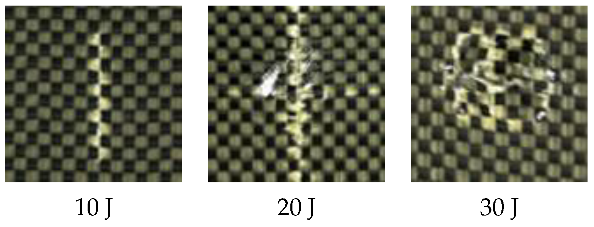
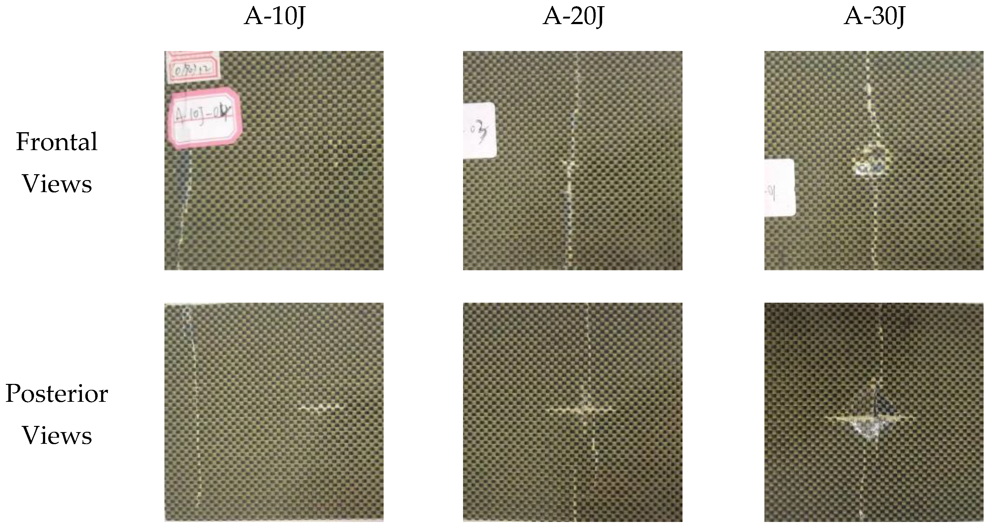
3.1.4. Analysis of Impact Damages

Figure 7 illustrates the development of cracks after impact on the specimens. The majority of the cracks exhibit a serrated pattern and are oriented perpendicular to the direction of the first layer of fibers in the composite laminates. The results clearly demonstrate the increasing level of damage associated with higher impact energies, offering valuable data on the mechanical characteristics of these materials.
The samples in Figure 7 sustain minimal and superficial injury at an impact energy level of 10 J. The three samples that were evaluated—10 J 01 Sample A, 10 J 02 Sample A and 10 J 03 Sample A—display only minor matrix cracking and mild fiber deformation. This implies that the composite laminate maintains a massive portion of its structural integrity when exposed to lower impact energies. The material’s capacity to withstand such impacts without sustaining substantial damage suggests that it has the potential to preserve structural integrity under mild stress conditions.
The damage to the samples is significantly more pronounced when the impact energy is enhanced to 20 J in comparison to the 10 J impacts. The samples—20 J 01 Sample A, 20 J 02 Sample A and 20 J 03 Sample A—display extensive fiber fracture, matrix disintegration and delamination. This extent of damage underscores a critical threshold beyond which the composite material initiates structural failure. A critical limit for safety and performance considerations is established when the imparted energy surpasses the material’s capacity to dissipate it without substantial damage.
The damage is severe and frequently catastrophic at the maximum tested impact energy of 30 J. All the samples that were evaluated at this level—30 J 01 Sample A, 30 J 02 Sample A and 30 J 03 Sample A—experience complete structural failures, which include entire perforations or “go-through” holes. Although the composite material is resilient under less severe impacts, such extreme damage suggests that it is not suitable for applications that may entail high-energy impacts. This is due to its inability to prevent penetration and maintain integrity under such conditions.
The impacted composite laminates were scanned using a C-scan to obtain the damaged area. Figure 8 provides morphologies on the damaged area of the samples. The C-scan images of specimen A, exposed to hits of 10 J, 20 J and 30 J, offer a comprehensive examination of the damage characteristics and their progression as the energy levels increase. The frontside C-scan reveals a localized damage region with a larger amplitude near the core, indicating concentrated impact energy but limited penetration for the 10 J strikes. The nearby region displays slight radial disruptions, indicating a certain level of energy dissipation across the composite layers. On the other hand, the opposite side of the specimen has a more dispersed pattern of damage with a generally reduced intensity, indicating that the rear surface had less significant deformation.
When the impact energy reaches 20 J, the damage becomes more noticeable, particularly on the front side Figure 8c, where a wider and more clearly defined core damage zone is observed. The central region, which is entirely black, indicates that there has been complete penetration into the composite material at this specific place. It is surrounded by an uneven pattern of reduced amplitude. This pattern suggests substantial structural collapse in the central impact area. Similarly, the image on the backside Figure 8d shows a greater extent of damage compared to the 10 J condition, with a bigger area of moderate amplitude variations suggesting a more significant structural degradation at a deeper level. At the maximum tested energy of 30 J, the frontside C-scan Figure 8e shows significant damage spread over a wide area. The non-uniform perimeter of the affected area and the extensive disturbance in amplitude indicate the occurrence of sophisticated material failure mechanisms, such as delamination and internal fracturing. This is additionally supported by the backside scan Figure 8f, in which the damage is so widespread that the entire area appears uniformly dark. This indicates that the impact energy has progressed beyond the material’s resistance and has pierced through a significant portion of the specimen.
This investigation demonstrates the substantial influence of impact energy on the spread of damage in composite materials. The transition from surface-level harm at lower levels of energy to profound structural breakdown at greater levels of energy underscores a non-linear correlation between the energy of impact and the extent and size of the harm. Comprehending these specific traits of damage is essential in the development of materials capable of enduring greater impact energies and in the creation of components that utilize the inherent advantages of composite materials to improve their safety and longevity.

3.2. Results of CAI Test and Discussion

3.2.1. CAI Damage Behavior

The compression load–displacement curves of all specimens subjected to low-velocity impacts are given in Figure 9. It can be found that the load of all laminates increases with the displacement in the pre-compression period, and then the loads increase linearly with the displacement. When the loads reach the maximum, the loads suddenly drop, indicating the failure of the composite laminate. At a stress level of 10 J, the curve exhibits the highest degree of smoothness, indicating minimal internal damage and demonstrating ductile behavior. As the energy of impact grows to 20 J and 30 J, the curves reach their highest points at earlier displacements. The curve at 30 J exhibits a sharp increase followed by a steep decline, indicating substantial internal damage and a significant decrease in material strength caused by the increased impact energy.
Table 1 shows the CAI strength of specimens. The results indicate that the residual compressive strengths decrease with the increase in the energy of the impact. The specimen in the A-0J group exhibits the highest CAI strength since the impact energy is zero. Since damage is caused by the impact to the laminate specimens in the A-10J to the A-30J groups, the greater the impact energy, the greater the damage, resulting in smaller CAI strength of the composite laminate subjected to the higher energy. The residual compressive strength under 30 J impact energy is only 68.28% of the unimpacted one. Although the impact with small energy reinforces the impact area, resulting in the smallest damaged area in the specimen, the internal occurrence of some cracks and delamination is inevitable after the impact.

3.2.2. The Damage Morphology after CAI

The visual views of the CAI failure of the specimen are shown in Figure 10. After CAI tests, delamination and buckling appear on both the front and back of the specimen. Observing the front and back of the specimen reveals that the damaged areas extend from the impact dent. However, the expansion of the damaged areas is not along the same route and from the same position, since irregular crack propagation occurs within the specimen during the impact process. Therefore, the expansion of the damaged area follows an inconsistent route during compression. It is worth noting that the damaged area hardly expands along the length direction, and basically along the width direction of the damaged area during the CAI test.

4. Conclusions

In this study, low-velocity impact (LVI) and compression after impact (CAI) tests were conducted on carbon/aramid hybrid woven composite laminates employed in marine crafts to investigate the effects of low-velocity impacts with different impact energies on CAI performance of composite laminates. Based on the reported results, the following conclusions may be drawn.
(1)
Under the condition of the different impact energy, the increase in the impact energy causes greater damage to the laminate. With the increase in impact energy, the peak force increases and the time to reach the peak force decreases. The hybrid laminates exhibit different load–displacement responses under different energy impacts. The energy absorption of the laminate is related to its plastic deformation capacity and the laminate.
(2)
The CAI strength decreases with the increase in the impact energy, and the specimen with 0 J impact energy has the highest CAI strength. The greater the impact energy, the greater the damage, resulting in smaller CAI strength of the composite laminate subjected to the higher energy. The residual compressive strength under 30 J impact energy is only 68.28% of the unimpacted one. The CAI damage areas of all specimens are cross-shaped and expand from the impact damage area.

Author Contributions

Conceptualization, D.C.; Methodology, Y.L., Y.J. and D.C.; Software, X.C.; Validation, Y.L., X.C. and Y.S.; Investigation, Y.L. and Y.J.; Resources, Y.S. and D.C.; Data curation, Y.L.; Writing—original draft, Y.L., Y.J. and X.C.; Writing—review & editing, Y.S. and D.C.; Visualization, Y.J.; Supervision, Y.S. and D.C.; Project administration, D.C.; Funding acquisition, Y.L. All authors have read and agreed to the published version of the manuscript.

Funding

This work was supported by the National Natural Science Foundation of China under grant 51509151, the Shanghai Commission of Science and Technology Project under grant 21DZ1201004 and 23010501900, in part by the Shandong Province Key Research and Development Project under grant 2019JZZY020713, and the Anhui Provincial Department of Transportation Project under grant 2021-KJQD-011.

Institutional Review Board Statement

Not applicable.

Informed Consent Statement

Not applicable.

Data Availability Statement

Data is contained within the article.

Conflicts of Interest

The authors declare no conflict of interest.

References

  1. Shyamsunder, L.; Maurya, A.; Rajan, S.D.; Cordasco, D.; Revilock, D.; Blankenhorn, G. Impact simulation of composite panels for aerospace applications. Compos. Part B Eng. 2022, 247, 110320. [Google Scholar] [CrossRef]
  2. Caminero, M.A.; García-Moreno, I.; Rodríguez, G.P. Damage resistance of carbon fibre reinforced epoxy laminates subjected to low velocity impact: Effects of laminate thickness and ply-stacking sequence. Polym. Test. 2017, 63, 530–541. [Google Scholar] [CrossRef]
  3. Johnson, A.F.; Toso-Pentecôte, N. 19—Determination of delamination damage in composites under impact loads. In Composites Science and Engineering, Delamination Behaviour of Composites; Sridharan, S., Ed.; Woodhead Publishing: Sawston, UK, 2008; pp. 561–585. [Google Scholar]
  4. Davies, G.; Irving, P. 11—Impact, post-impact strength, and post-impact fatigue behavior of polymer composites. In Composites Science and Engineering; Irving, P., Soutis, C., Eds.; Woodhead Publishing: Sawston, UK, 2020; pp. 303–330. [Google Scholar]
  5. Yudhanto, A.; Wafai, H.; Lubineau, G.; Goutham, S.; Mulle, M.; Yaldiz, R.; Verghese, N. Revealing the effects of matrix behavior on low-velocity impact response of continuous fiber-reinforced thermoplastic laminates. Compos. Struct. 2019, 210, 239–249. [Google Scholar] [CrossRef]
  6. Sun, X.C.; Hallett, S.R. Failure mechanisms and damage evolution of laminated composites under compression after impact (CAI): Experimental and numerical study. Compos. Part A Appl. Sci. Manuf. 2018, 104, 41–59. [Google Scholar] [CrossRef]
  7. Abir, M.R.; Tay, T.E.; Ridha, M.; Lee, H.P. On the relationship between failure mechanism and compression after impact (CAI) strength in composites. Compos. Struct. 2017, 182, 242–250. [Google Scholar] [CrossRef]
  8. Rozylo, P.; Debski, H.; Kubiak, T. A model of low-velocity impact damage of composite plates subjected to Compression-After-Impact (CAI) testing. Compos. Struct. 2017, 181, 158–170. [Google Scholar] [CrossRef]
  9. Kodagali, K.; Rad, C.V.; Sockalingam, S.; Gurdal, Z.; Miller, E. Low velocity impact and compression-after-impact response of hybrid pseudo-woven meso-architectured carbon/epoxy composite laminates manufactured via automated fiber placement. Compos. Part B Eng. 2024, 271, 111154. [Google Scholar] [CrossRef]
  10. Ma, B.; Cao, X.; Feng, Y.; Song, Y.; Yang, F.; Li, Y.; Zhang, D.; Wang, Y.; He, Y. A comparative study on the low velocity impact behavior of UD, woven, and hybrid UD/woven FRP composite laminates. Compos. Part B Eng. 2024, 271, 111133. [Google Scholar] [CrossRef]
  11. Zhu, X.; Chen, W.; Liu, L.; Luo, G.; Zhao, Z. Experimental and numerical investigation on the compression after high-velocity impact behavior of composite laminates. Eng. Fail. Anal. 2024, 159, 108125. [Google Scholar] [CrossRef]
  12. Kumar, Y.; Rezasefat, M.; Amico, S.C.; Manes, A.; Dolez, P.I.; Hogan, J.D. Comparison of two progressive damage models for predicting low-velocity impact behavior of woven composites. Thin-Walled Struct. 2024, 197, 111611. [Google Scholar] [CrossRef]
  13. Zhao, Q.; Wang, W.; Liu, Y.; Hou, Y.; Li, J.; Li, C. Multiscale modeling framework to predict the low-velocity impact and compression after impact behaviors of plain woven CFRP composites. Compos. Struct. 2022, 299, 116090. [Google Scholar] [CrossRef]
  14. Melaibari, A.; Wagih, A.; Basha, M.; Lubineau, G.; Al-Athel, K.; Eltaher, M.A. Sandwich composite laminate with intraply hybrid woven CFRP/dyneema core for enhanced impact damage resistance and tolerance. J. Mater. Res. Technol. 2022, 21, 1784–1797. [Google Scholar] [CrossRef]
  15. Ni, K.; Chen, Q.; Wen, J.; Cai, Y.; Zhu, Z.; Li, X. Low-velocity impact and post-impact compression properties of carbon/glass hybrid yacht composite materials. Ocean. Eng. 2024, 292, 116448. [Google Scholar] [CrossRef]
  16. Anuse, V.S.; Shankar, K.; Velmurugan, R.; Ha, S.K. Compression-After-Impact analysis of carbon/epoxy and glass/epoxy hybrid composite laminate with different ply orientation sequences. Thin-Walled Struct. 2023, 185, 110608. [Google Scholar] [CrossRef]
  17. Yin, H.; Iannucci, L. An experimental and finite element investigation of compression-after-impact (CAI) behaviour of biaxial carbon fiber non-crimp-fabric (NCF) based composites. Compos. Struct. 2022, 281, 115057. [Google Scholar] [CrossRef]
  18. Anuse, V.S.; Shankar, K.; Velmurugan, R.; Ha, S.K. Compression-After-Impact analysis of carbon fiber reinforced composite laminate with different ply orientation sequences. Int. J. Impact Eng. 2022, 167, 104277. [Google Scholar] [CrossRef]
  19. Zhou, J.; Liu, B.; Wang, S. Finite element analysis on impact response and damage mechanism of composite laminates under single and repeated low-velocity impact. Aerosp. Sci. Technol. 2022, 129, 107810. [Google Scholar] [CrossRef]
  20. Lei, Z.X.; Ma, J.; Sun, W.K.; Yin, B.B.; Liew, K.M. Low-velocity impact and compression-after-impact behaviors of twill woven carbon fiber/glass fiber hybrid composite laminates with flame retardant epoxy resin. Compos. Struct. 2023, 321, 117253. [Google Scholar] [CrossRef]
  21. ASTM-D7136/D7136M-15; Standard Test Method for Measuring the Damage Resistance of a Fiber-Reinforced Polymer Matrix Composite to a Drop-Weight Impact Event. ASTM International: West Conshohocken, PA, USA, 2015.
  22. ASTM-D7137/D7137M-12; Standard Test Method for Compressive Residual Strength Properties of Damaged Polymer Matrix Composite Plates. ASTM International: West Conshohocken, PA, USA, 2012.
Figure 1. Instron CEAST 9350 and specimen for LVI test.
Coatings 14 00986 g001
Figure 2. Test fixture and specimen of compression after impact.
Coatings 14 00986 g002
Figure 3. The UltraPACTM immersion C-scan device BSN-C1285.
Coatings 14 00986 g003
Figure 4. Impact force–time curves. (a) 10 J; (b) 20 J; (c) 30 J.
Coatings 14 00986 g004
Figure 5. Impact force–displacement curves. (a) 10 J; (b) 20 J; (c) 30 J.
Coatings 14 00986 g005
Figure 6. Impact energy–time curves. (a) 10 J; (b) 20 J; (c) 30 J.
Coatings 14 00986 g006aCoatings 14 00986 g006b
Figure 7. Impact damages for specimens.
Coatings 14 00986 g007
Figure 8. The delamination damage morphologies of composite laminates after impacts. (a) 10 J frontside, (b) 10 J backside, (c) 20 J frontside, (d) 20 J backside, (e) 30 J frontside, (f) 30 J backside.
Coatings 14 00986 g008
Figure 9. Compression load–displacement curves.
Coatings 14 00986 g009
Figure 10. The damage morphologies of composite laminates after CAI.
Coatings 14 00986 g010
Table 1. CAI strengths of the composite laminates.
SpecimenForce (kN)Displacement (mm)Residual Strength (%)
A-0J62.991.91100.00%
A-10J54.721.9886.87%
A-20J50.932.1080.85%
A-30J43.011.6268.28%
Disclaimer/Publisher’s Note: The statements, opinions and data contained in all publications are solely those of the individual author(s) and contributor(s) and not of MDPI and/or the editor(s). MDPI and/or the editor(s) disclaim responsibility for any injury to people or property resulting from any ideas, methods, instructions or products referred to in the content.

