Abstract
This study investigates the influence of various tool coatings, cutting speeds, and feed per tooth values on cutting forces during the CNC milling of Medium Density Fiberboard (MDF). The coatings tested include reference, TripleSi, Hyperlox, DLC, and lapped coatings. Experiments were conducted using an SCM Morbidelli m100 CNC milling machine under controlled conditions. Cutting speeds were set at 8, 10, and 12 m/s, while feed per tooth values were varied at 0.1, 0.2, and 0.3 mm. Cutting forces were measured using a three-axis piezoelectric dynamometer Kistler, and the data were analyzed to determine the impact of these variables on cutting performance. The results revealed that while cutting speed had a minimal effect on cutting forces, feed per tooth significantly influenced them, with higher values of feed per tooth leading to increased forces. Among the coatings, lapped and TripleSi exhibited the lowest cutting forces, whereas DLC showed the highest. Statistical analysis, including ANOVA and Scheffé tests, confirmed the significant differences between the coatings and highlighted the superior performance of the lapped and TripleSi coatings in reducing cutting forces.
1. Introduction
The optimization of machining processes is critical in manufacturing industries to enhance productivity, reduce operational costs, and improve the quality of final products. In the context of CNC milling, the selection of appropriate machining parameters is vital for achieving these goals. Key parameters such as cutting speed and feed speed are the main machining parameters affecting the cutting forces and significantly influence the efficiency and effectiveness of the milling process. Cutting forces play a critical role in the milling process and have significant effects on both the tool and the workpiece [1]. They influence not only the immediate performance metrics such as tool wear [2] and surface finish [3] but also have broader implications for energy consumption and process efficiency [1,4]. High cutting forces can lead to excessive tool wear, which shortens tool life and increases costs due to frequent tool changes and longer machining times [2]. Moreover, cutting forces directly affect the surface quality and dimensional accuracy of the workpiece. Machine stability is also impacted, as high cutting forces can induce vibrations, reducing the machine’s accuracy and increasing the risk of machine failure [2,5]. Importantly, cutting forces are related to the energy consumption of the milling process, with higher forces requiring higher power consumption and increasing operational costs [4]. Lower cutting forces typically correspond to lower energy consumption, making the process more cost-effective and environmentally friendly. Therefore, optimizing cutting forces is crucial for enhancing productivity, reducing energy consumption, and maintaining high product quality in manufacturing processes [6].
Cutting speed directly influences the rate of material removal and the thermal dynamics at the cutting interface. Higher cutting speeds can lead to increased temperatures, which in turn may affect tool wear and the quality of the machined surface. According to [7,8,9] optimizing cutting speed is essential and has a direct influence on power consumption, tool wear, heat generation and quality of the machined surface. According to the literature, contradictory results are reported about the cutting speed impact on cutting forces. Some studies have found that cutting speed has practically no impact on cutting forces [10,11,12]. Conversely, other research has shown that cutting forces change linearly with increasing speeds [13,14] or that higher cutting speeds lead to increased cutting forces [14,15,16]. In [17], the authors reported reductions in both parallel and normal cutting forces with higher cutting speeds. These differences in results can be attributed to the use of different cutting speed ranges, wood species, machining processes, and methods of measuring cutting forces [17].
Feed per tooth affects the load on each cutting edge and the overall cutting force required. In [18], the study indicates that feed per tooth is an important factor in determining tool performance. Higher feed speeds typically result in greater cutting forces, potentially leading to tool deflection and increased wear. In [19], the authors also found that both parallel and normal forces increase as the feed speed rises. Other studies have confirmed that cutting power and cutting force increase with feed speed [20,21,22,23] and depth of cut [17,24,25]. An increase in feed per tooth corresponds to an increase in chip thickness [26,27,28], generally resulting in greater cutting forces and power requirements. This relationship has been supported by the findings of [15,20,29,30,31].
There are many ways to improve tool performance [32] and most are inspired by bionic solutions invented by nature [33]. Besides other techniques of eliminating tribological phenomena leading to tool wear such as bionic texturing [34] and its optimization [35], tool coatings play a pivotal role [36]. Apart from friction reduction, tool coatings are applied to improve heat transfer of the tool–chip system [37], tool hardness, or wear resistance. Widely popular coatings such as titanium nitride (TiN), aluminum titanium nitride (AlTiN) [38], and diamond-like carbon (DLC) have been extensively studied for their benefits in extending tool life and improving cutting efficiency [39]. For instance, [40] demonstrated that DLC coatings significantly reduce the friction coefficient, thereby minimizing the risk of reaching critical temperatures during machining. The leading trend is to combine different types of coatings into a multilayer application which leads to an even better performance of cutting tools [41,42].
However, the impact of tool coatings on cutting forces, particularly in wood or wood-based materials machining, is less documented in the literature. Most research focuses on tool wear, adhesion, and friction reduction, for example [43,44,45,46,47], with limited comprehensive studies addressing their influence on cutting parameters such as cutting force. Understanding this influence is crucial for optimizing machining conditions and selecting appropriate coatings for specific applications. In the work [18], the authors highlighted that coatings which significantly reduce friction can lead to lower energy consumption, less tool wear, and better surface quality. Given the scarcity of literature on the impact of tool coatings on cutting forces during MDF milling, this study aims to fill this gap by systematically investigating the effects of different coatings, cutting speeds, and feed per tooth.
The objective of this paper is to systematically evaluate the effects of different tool coatings, cutting speeds, and feed per tooth values on cutting forces during CNC milling of MDF.
2. Materials and Methods
2.1. Machine
The machining was performed using a CNC milling machine (SCM Morbidelli m100, SCM Group, Rimini, Italy) in the workshop facilities of Mendel University in Brno. During machining, the dust extraction hood was lifted to prevent interference with the measurements.
2.2. Tool
Five hard metal tools with different surface modifications were tested. One reference tool without coating was included, and a simple lapped surface was also tested to assess the influence of this cost-effective modification on wood machining. The remaining tools were coated with three different promising coatings for wood-based material machining: TripleSi, Hyperlox, and DLC.
- TripleSi Coating: This coating consists of three layers. The first layer is titanium nitride, which has excellent adhesion properties to hard metal and is typically used as the final coating for conventional wood machining tools (golden layer). The second layer is aluminum titanium nitride, also tested alone as Hyperlox coating. This layer has an optimal ratio of hardness and toughness, high-temperature resistance up to 1200 °C, and when heated, forms a microscopic corundum layer that further protects the tool against abrasion, making it suitable for machining hard laminates. The top layer is rich in silicon nanostructures, providing superior surface hardness and protecting against oxidation during machining.
- Hyperlox Technology: Similar to the middle layer of the TripleSi coating, but with an improved coating process that promises 20 % longer edge life.
- Diamond-Like Carbon (DLC) Technology “CCDia Fiber Speed”: This technology is based on a tetrahedral amorphous structure with more than 80 % sp3 concentration. The amorphous structure gives the DLC coating a hardness very close to natural diamond (up to 10,000 HV, Vickers Hardness) and an extremely low friction coefficient (<0.1).
These coatings were applied to 10 mm router bits with one straight edge, manufactured by Vydona (Vydona, Pravčice, Czech Republic). The cutting tools are made from CTS20D, a material known for its excellent properties suitable for machining applications (Table 1 and Figure 1). Below is a detailed overview of its characteristics (Table 2). Tools with a straight edge were chosen to eliminate the effect of forces acting on the Z-axis.

Table 1.
Material properties of cutting tool.
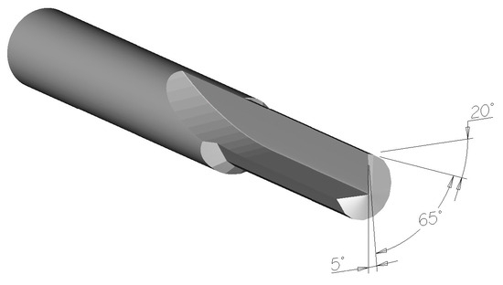
Figure 1.
Cutting geometry of the cutting tool.
Table 2.
Specifications of tools with various coatings used in the experiment.
2.3. Sample and Cutting Conditions
Medium Density Fiberboard (MDF) with a thickness of 18 mm was chosen for its homogeneity. This experiment will serve as a pretest; in the next phase, solid wood will be tested.
The boards used in the experiment had a density of 770 kg/m3 and a moisture content of 7.5 %, with dimensions of 300 mm × 155 mm × 18 mm before milling.
Both conventional and climb milling were performed with a material removal of 1 mm, and various cutting conditions were tested, see Table 3. Measurements were conducted first on the bottom edge with conventional milling, then adjusted to the top edge for climb milling. Cutting force (Fc) was calculated from the measured Fx and Fy forces. Each modified cutting condition was tested ten times for statistical evaluation.
Table 3.
Cutting parameters.
2.4. Measuring Equipment
Forces were measured using a three-axis piezoelectric dynamometer (Kistler 9257B, Kistler Holding AG, Winterthur, Switzerland). The setup included a notebook with DynoWare evaluation software, a DAQ system-bus (5697A DAQ), a 5070A multi-channel amplifier, and the Kistler 9257 B piezoelectric three-axis dynamometer, for experimental setup see Figure 2.
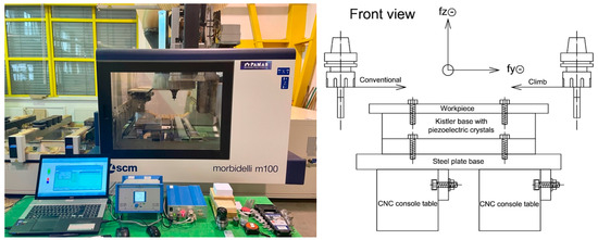
Figure 2.
Left: Experimental setup with CNC milling machine; Right: Schematic front view of the milling setup showing the orientations of cutting forces during conventional and climb milling.
The measuring time was set to 15 s to ensure sufficient data recording. However, for higher feed speeds, this proved excessive, and measurements were manually stopped. The sampling frequency was set to 5000 Hz to analyze the dynamic forces on the cutter blade. No additional filtering was performed on the original data. The average forces for each treatment were determined with Dynoware software. Data were processed and statistically evaluated using MS Excel.
2.5. Analysis of the Issue
In both climb and conventional milling kinematics, the chip thickness varies [48]. Therefore, calculations must be performed at the midpoint of the angle of engagement (ψ/2), where the average chip thickness (hm) and the average cutting force can be expected.
The angle of engagement is calculated according to Equation (1):
where R is the radius of the cutter (m), e is the depth of cut (m).
The average chip thickness (hm) used in the calculation models is given by:
The feed per tooth (fz) can be expressed according to:
where vf is the feed speed (m/min), n is the rotational speed (rpm), z is the number of teeth.
Dynamic analysis is based on the Ernst—Merchant force diagram (Figure 3). When measuring forces on the sample using a three-axis dynamometer, the axial component in the Z-direction is zero due to the use of a straight-edge cutter. The total active force of the cutting process (Fa) can be calculated using the Pythagorean theorem from the measured forces in the X and Y directions (Fx is perpendicular to the feed direction, and Fy is equal to the force in the feed direction, Fy ≡ Ff):
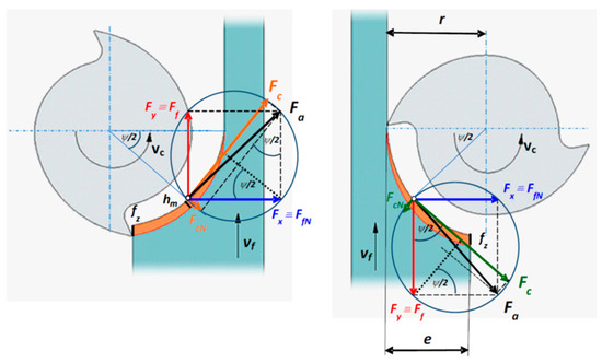
Figure 3.
Diagram of cutting forces and chip formation in climb and conventional milling [23].
The cutting force (Fc) in the direction of the tool’s main movement can be calculated using the components of the Fx and Fy forces and the trigonometric functions of the ψ/2 half angle of engagement (Figure 3):
Conventional milling:
Climb milling:
These equations allow for the accurate calculation of the cutting forces during the milling process, providing essential data for the analysis and optimization of milling parameters.
3. Results
Ten cuts were made with each router bit, for both conventional and climb milling. A selected measurement record of individual components of cutting force is presented in Figure 4. The DynoWare application of the Kistler measuring system allows direct analysis of the measured data in the displayed graph, i.e., it is possible to determine the mean values of the forces Fx (blue progress), Fy (red progress), and Fz (green progress).

Figure 4.
Measurement record for lapped surface (vc = 10 m/s; fz = 0.3 mm; conventional milling).
Table 4 and Table 5 present average values of cutting forces calculated for different tool coatings at various cutting speeds and feed per tooth values, along with the percentage comparison to the reference coating.
Table 4.
Average cutting forces for conventional milling.
Table 5.
Average cutting forces for climb milling.
In both conventional and climb milling, the DLC coating generally shows the highest cutting forces across all cutting speeds and feeds per tooth, indicating poorer performance. The lapped surface shows the lowest cutting forces, indicating the best performance in both conventional and climb milling.
The ranking of coatings in terms of performance (from best to worst) is consistent in both tables: lapped, TripleSi, Hyperlox, reference, and DLC. However, the actual values of cutting forces are slightly different between conventional and climb milling, with climb milling generally showing slightly higher forces for the same parameters.
3.1. Feed Per Tooth Effect
Figure 5 depicts the relationship between the cutting force (Fc) and the feed per tooth (fz) for various tool coatings used in conventional milling and climb milling.

Figure 5.
Average values of cutting forces as a function of feed per tooth for different cutting speeds and tool coatings.
As expected, the cutting force increases linearly with the feed per tooth in both conventional and climb milling. However, the rate of increase varies depending on the coating, with the DLC showing the most significant increase.
The analysis of the one-way ANOVA demonstrated a statistically significant effect of the feed per tooth on the cutting forces. The values of the test criteria F, Fcrit, and P confirm the existence of statistically significant differences between the mean values, leading to the rejection of the null hypothesis. This necessitated the use of a multiple comparison test, such as the Scheffé test, to further explore these differences.
The results of the Scheffé test confirm that there is a statistically significant difference between the mean values of all tested feed per tooth values (Table 6). Based on the statistical analysis, it can be concluded that variations in the feed per tooth have a significant impact on the cutting forces experienced during milling.
Table 6.
Scheffé test results for cutting forces in conventional and climb milling at different feed per tooth values.
3.2. Cutting Speed Effect
For conventional milling (Table 4 and Figure 6), across all feed per tooth values, the cutting forces generally exhibit a trend where they decrease at a cutting speed of 10 m/s and then increase again at 12 m/s. This trend is consistent across all coatings tested.
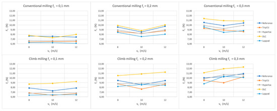
Figure 6.
Average values of cutting forces as a function of cutting speed for different feed per tooth values and tool coatings.
For climb milling (Table 5 and Figure 6), across all feed per tooth values, the general trend observed is that cutting forces increase with the cutting speed. This indicates that higher cutting speeds lead to increased cutting forces, likely due to increased friction and heat generation at higher speeds. However, it is noteworthy that some coatings, particularly the reference and TripleSi, exhibit a dip in cutting forces at vc = 10 m/s, followed by the highest cutting forces at vc = 12 m/s.
Figure 6 illustrates the relationship between the cutting force (Fc) and the cutting speed (vc) for various tool coatings during conventional and climb milling.
The results of the one-way ANOVA test (Table 7, Table 8, Table 9 and Table 10) indicate that when the cutting speed is varied, the test criterion F is lower than the critical value Fcrit, and the p-value is higher than the significance level α (0.05). These indicators suggest that the change in cutting speed is not statistically significant.
Table 7.
Summary statistics of cutting forces for different cutting speeds in conventional milling.
Table 8.
ANOVA results for cutting forces at different cutting speeds in conventional milling.
Table 9.
Summary statistics of cutting forces for different cutting speeds in climb milling.
Table 10.
ANOVA results for cutting forces at different cutting speeds in climb milling.
Based on the statistical analysis, it can be concluded that variations in cutting speed do not have a significant impact on the cutting forces experienced during milling. This insight is valuable for the optimization of milling operations, where other parameters might be prioritized over cutting speed to achieve the desired outcomes.
3.3. Tool Coating Effect
The one-way ANOVA test results indicate that there are statistically significant differences in the cutting forces between the different tool coatings. Given the significant F-value and the very low p-value, we reject the null hypothesis that all group means are equal. This confirms that the type of tool coating significantly impacts the cutting force experienced during milling.
Based on these results, we performed post hoc multiple comparison tests using the Scheffé test to identify which specific groups (tool coatings) differ significantly from each other (Table 11).
Table 11.
Scheffé test results for cutting forces across different tool coatings.
The Scheffé test results demonstrate that the lapped coating is significantly more effective in reducing cutting forces compared to the reference and DLC coatings. The DLC coating consistently results in higher cutting forces, making it less desirable for operations aiming to minimize cutting forces. TripleSi and Hyperlox coatings perform similarly to each other and the lapped coating, indicating their potential for efficient milling with reduced cutting forces.
4. Discussion
The study investigated the effects of various tool coatings, cutting speed, and feed per tooth on the cutting forces during the milling of MDF. Through a comprehensive experimental design and statistical analysis, several key findings were established, contributing to the understanding of optimal milling conditions and tool performance.
4.1. Feed Per Tooth Effect
In contrast to cutting speed, the feed per tooth was found to have a statistically significant impact on cutting forces, as demonstrated by the results of both the ANOVA and Scheffé test. Higher feed speed consistently resulted in increased cutting forces, indicating that careful optimization of feed per tooth is essential for efficient milling operations. These findings are in agreement with previous studies, which emphasized the critical role of feed speed in determining cutting force and tool wear during wood milling. The observations made by [19,49] noted the significant impact of feed rate on cutting forces, corroborating our results. Furthermore, studies by [17,29] noted significant increases in cutting forces and cutting power with higher feed speeds in composite material milling. The authors in [50] determined that feed speed was the most influential parameter affecting cutting force. The reasons for these observed differences can be attributed to the mechanics of chip formation and the interaction between the cutting tool and the material. Higher feed per tooth values lead to increased chip thickness, which requires more force to shear the material effectively. This increased force results in higher friction between the tool and the workpiece, generating more heat and potentially leading to poorer surface finishes. Moreover, the higher forces can lead to increased tool wear and deflection, reducing the overall efficiency of the milling process. While some studies, such as those by [24], suggested that increasing feed per tooth can lead to more energy-efficient cutting, our findings indicate a different trend where cutting forces gradually increase with higher feed speeds. This discrepancy may be due to the specific properties of MDF and the conditions under which the experiments were conducted. The fibrous and heterogeneous nature of MDF may cause higher friction and adhesion at higher feed speeds, leading to increased cutting forces.
4.2. Cutting Speed Effect
The results of the one-way ANOVA test revealed that variations in cutting speed do not significantly affect the cutting forces. However, a specific trend was observed where cutting forces decreased at 10 m/s and then increased again at 12 m/s. This was particularly noticeable for certain coatings (e.g., reference and TripleSi), suggesting an optimal cutting speed for minimizing cutting forces. Conversely, the increase in cutting forces at 12 m/s may be due to higher friction and heat generation, which could soften the MDF material and increase adhesion between the tool and workpiece. This aligns with findings from [12,30], who also reported the minimal impact of cutting speed on cutting forces. Conversely, the increase in cutting forces at 12 m/s may be due to higher friction and heat generation, which could soften the MDF material and increase adhesion between the tool and workpiece. This effect is supported by the work of [14,15,16], who observed increased cutting forces at higher cutting speeds. According to [51], cutting speed is a factor accelerating tool wear and the cutting forces are sometimes increased and decreased with cutting speed. The authors in [17] discussed that higher cutting speed corresponds to higher productivity and efficient cutting, which was indicated by a reduction in the parallel and normal cutting forces.
The observed decrease in cutting forces at 10 m/s can be attributed to more efficient chip evacuation and reduced frictional forces at this speed. At this optimal speed, the cutting edge engages the material in a manner that minimizes resistance, leading to smoother cutting and lower force requirements. This suggests that there is a balance between cutting speed and the resultant cutting force, where the interaction between the tool and MDF is optimized to reduce friction and improve chip flow. Conversely, the increase in cutting forces at 12 m/s may result from elevated friction and heat generation. Higher cutting speeds often lead to increased temperatures at the cutting interface, which can soften the MDF material and increase its adhesion to the tool surface. This increased adhesion results in higher cutting resistance and thus greater cutting forces. Additionally, the higher cutting speed may exacerbate tool wear, further increasing the cutting forces due to the degraded cutting-edge condition.
The variability in cutting forces with changes in cutting speed highlights the complex nature of the cutting process. While some studies, such as those by [10,11,12], found that cutting speed has minimal impact on cutting forces; other researchers, including [14], observed significant effects. These differences may be attributed to the specific material properties, tool geometry, and cutting conditions used in each study.
4.3. Tool Coating Effect
The Scheffé test results provided significant insights into the comparative performance of different tool coatings in terms of cutting forces. The lapped coating is the most effective in reducing cutting forces. The DLC coating is less effective, resulting in the highest cutting forces, indicating its lesser suitability for MDF milling under the tested conditions. TripleSi and Hyperlox coatings offered moderate improvements over the reference coating but did not differ significantly from each other. These findings are crucial for selecting the optimal tool coating to enhance milling performance, reduce energy consumption, and extend tool life.
The superior performance of the lapped and TripleSi coatings can be attributed to their smoother surfaces and higher hardness, which reduce friction and wear during the cutting process. The lapped surface minimizes contact area, reducing frictional forces and cutting resistance. However, due to the properties of the lapped surface, the time-consuming production process, and the fact that lapping does not improve the hardness of the tool, the lapped surface tool may have a shorter tool life. Therefore, the tool with the TripleSi coating, known for its hardness and low friction properties, is a more suitable choice, balancing efficiency and durability. These observations are consistent with studies by [45,46], who reported enhanced tool performance with similar coatings. On the other hand, the higher cutting forces observed with the DLC coating may be due to its higher friction coefficient when interacting with MDF. While DLC-coated tools perform well with hard and exotic woods, as well as woods with high resin content, their interaction with the fibrous structure of MDF may lead to increased adhesion and friction, resulting in higher cutting forces. The fibrous nature of MDF can cause the DLC coating to generate more friction and adhere more to the material, increasing the cutting force required. This highlights the importance of selecting coatings based on the specific material being machined.
Comparing these findings with those of other authors is challenging due to the lack of information in the available literature regarding the influence of tool coatings on cutting parameters or their comprehensive investigations. Most research focuses on the impact of tool coatings on tool wear, adhesion, and friction. The effect on cutting forces is predominantly discussed only in the context of metal machining.
4.4. Conventional and Climb Milling Effect
In comparing the experimentally measured forces, we observe higher values of the resulting cutting forces in the climb milling process. According to [23], using a climb-cutting mode requires more cutting power than conventional cutting. This observation is supported by [24], who also noted that climb milling demands significantly more cutting power compared to conventional milling.
4.5. Practical Implications
The practical implications of these findings are significant for the optimization of milling operations. The non-significant impact of cutting speed on cutting forces allows for flexibility in speed adjustments without negatively affecting the milling performance. In contrast, the significant impact of feed per tooth underscores the need for careful parameter selection to balance cutting efficiency and tool life. Additionally, the superior performance of the lapped surface and specific coatings like TripleSi and Hyperlox suggests that these modifications can enhance tool performance, leading to reduced cutting forces, lower energy consumption, and potentially extended tool life.
4.6. Future Work
In the next phase of the research, measurements will be conducted under the same cutting conditions but using native beech and spruce wood to confirm or refute the current hypothesis. This will help determine whether the observed trends hold true for different wood types and further refine the optimization of CNC milling parameters for various materials. Additionally, helical routers with the same coatings will be used in this phase to further investigate the effects of tool geometry and coating on cutting forces.
5. Conclusions
This study investigates the influence of tool coatings, cutting speed, and feed per tooth on cutting forces during CNC milling of MDF boards. The results provide valuable insights into optimizing machining parameters for improved efficiency and tool life. Key findings include:
- Cutting speed effect: The cutting speed showed a non-significant impact on cutting forces, allowing flexibility in speed adjustments without negatively affecting milling performance. The optimal cutting speed observed for minimizing cutting forces across different coatings was found to be 10 m/s, where certain coatings (notably reference and TripleSi) exhibited a reduction in cutting forces.
- Feed per tooth effect: The feed per tooth significantly influenced cutting forces, with higher feed speeds resulting in greater cutting forces. To optimize cutting efficiency and tool life, a feed per tooth value of 0.1 mm is recommended, as it consistently resulted in lower cutting forces across all tested coatings.
- Tool coatings: Among the tested coatings, the lapped surface and TripleSi coating consistently demonstrated the lowest cutting forces, making them the most efficient choices for MDF milling. In contrast, the DLC coating resulted in the highest cutting forces, indicating it may not be suitable for MDF milling under the tested conditions.While the lapped surface provides low cutting forces, its time-consuming production process and lack of hardness improvement could lead to a shorter tool life. Therefore, the tool with the TripleSi coating is a more suitable choice, balancing efficiency and durability. Thus, the TripleSi coating is recommended for optimal performance due to its effective combination of low cutting forces and extended tool life.
- In summary, under our specific machining conditions, the optimal parameters for CNC milling of MDF to minimize cutting forces are a cutting speed of 10 m/s, a feed per tooth value of 0.1 mm, and the use of tools with TripleSi coating. These findings can guide the selection of appropriate machining parameters and tool coatings in real operating conditions. By reducing cutting forces, these parameters help minimize tool wear, lower energy consumption, and improve surface quality. This can lead to more cost-effective and environmentally friendly manufacturing processes, as lower cutting forces generally translate to lower energy consumption.
Author Contributions
Conceptualization, L.H., J.P. and V.N.; methodology, L.H., J.P. and V.N.; software, V.N.; validation, L.H., J.P. and V.N.; formal analysis, L.H.; investigation, L.H.; resources, V.N.; data curation, V.N.; writing—original draft preparation, L.H.; writing—review and editing, L.H. and J.P.; visualization, L.H.; supervision, J.P.; project administration, L.H.; funding acquisition, L.H. All authors have read and agreed to the published version of the manuscript.
Funding
This research was funded by the Specific University Research Fund MENDELU IGA-LDF-22-TP-004: “Advanced tool materials and their influence on the parameters of CNC machining of wood-based materials” and by European Union’s Horizon 2020 research and innovation programme under grant agreement No. 952314.
Institutional Review Board Statement
Not applicable.
Informed Consent Statement
Not applicable.
Data Availability Statement
Data are contained within the article.
Conflicts of Interest
The authors declare no conflicts of interests.
References
- Petre, I.M.; Găvruş, C. Influence of the Cutting Force upon Machining Process Efficiency. Mater. Today Proc. 2023, 72, 586–593. [Google Scholar] [CrossRef]
- Hernández-González, L.W.; Curra-Sosa, D.A.; Pérez-Rodríguez, R.; Zambrano-Robledo, P.D. Modeling Cutting Forces in High-Speed Turning Using Artificial Neural Networks. TecnoLógicas 2021, 24, 43–61. [Google Scholar] [CrossRef]
- Chatterjee, K.; Zhang, J.; Dixit, U.S. Data-driven Framework for the Prediction of Cutting Force in Turning. IET Collab. Intell. Manuf. 2020, 2, 87–95. [Google Scholar] [CrossRef]
- Velchev, S.; Kolev, I.; Ivanov, K.; Gechevski, S. Empirical Models for Specific Energy Consumption and Optimization of Cutting Parameters for Minimizing Energy Consumption during Turning. J. Clean. Prod. 2014, 80, 139–149. [Google Scholar] [CrossRef]
- Stephenson, D.A.; Agapiou, J.S. Metal Cutting Theory and Practice; CRC Press: Boca Raton, FL, USA, 2018; ISBN 1-315-37311-4. [Google Scholar]
- Venkatesan, K.; Manivannan, K.; Devendiran, S.; Mathew, A.T.; Ghazaly, N.M.; Benny, S.N. Study of Forces, Surface Finish and Chip Morphology on Machining of Inconel 825. Procedia Manuf. 2019, 30, 611–618. [Google Scholar] [CrossRef]
- Wyeth, D.J.; Goli, G.; Atkins, A.G. Fracture Toughness, Chip Types and the Mechanics of Cutting Wood. A Review COST Action E35 2004–2008: Wood Machining–Micromechanics and Fracture. Holzforschung 2009, 63, 2. [Google Scholar] [CrossRef]
- Guo, X.; Li, R.; Cao, P.; Ekevad, M.; Cristóvão, L.; Marklund, B.; Grönlund, A. Effect of Average Chip Thickness and Cutting Speed on Cutting Forces and Surface Roughness during Peripheral up Milling of Wood Flour/Polyvinyl Chloride Composite. Wood Res 2015, 60, 147–156. [Google Scholar]
- Marchal, R.; Mothe, F.; Denaud, L.-E.; Thibaut, B.; Bleron, L. Cutting Forces in Wood Machining–Basics and Applications in Industrial Processes. A Review COST Action E35 2004–2008: Wood Machining–Micromechanics and Fracture. Holzforschung 2009, 63, 2. [Google Scholar] [CrossRef]
- Franz, N.C. An Analysis of Chip Formation in Wood Machining; University of Michigan: Ann Arbor, MI, USA, 1958. [Google Scholar]
- McKenzie, W.M. Fundamental Aspects of the Wood Cutting Process; University of Michigan: Ann Arbor, MI, USA, 1961; ISBN 9798658308999. [Google Scholar]
- Eyma, F.; Méausoone, P.-J.; Larricq, P.; Marchal, R. Utilization of a Dynamometric Pendulum to Estimate Cutting Forces Involved during Routing. Comparison with Actual Calculated Values. Ann. For. Sci. 2005, 62, 441–447. [Google Scholar] [CrossRef]
- Pahlitzsch, G.; Dziobek, K. Untersuchungen Über Das Bandschleifen von Holz Mit Geradliniger Schnittbewegung. Holz Als Roh-Und Werkst. 1959, 17, 121–134. [Google Scholar] [CrossRef]
- Porankiewicz, B.; Bermudez, E.J.; Tanaka, C. Cutting Forces by Peripheral Cutting of Low Density Wood Species. BioResources 2007, 2, 671–681. [Google Scholar] [CrossRef]
- Axelsson, B.O.M.; Lundberg, Å.S.; Grönlund, J.A. Studies of the Main Cutting Force at and near a Cutting Edge. Holz. Als. Roh- Und Werkst. 1993, 51, 43–48. [Google Scholar] [CrossRef]
- Porankiewicz, B.; Axelsson, B.; Grönlund, A.; Marklund, B. Main and Normal Cutting Forces by Machining Wood of Pinus Sylvestris. BioResources 2011, 6, 27. [Google Scholar] [CrossRef]
- Moradpour, P.; Scholz, F.; Doosthoseini, K.; Tarmian, A. Measurement of Wood Cutting Forces during Bandsawing Using Piezoelectric Dynamometer. Drv. Ind. 2016, 67, 79–84. [Google Scholar] [CrossRef]
- Sheikh-Ahmad, J.Y.; Morita, T. Tool Coatings for Wood Machining: Problems and Prospects. For. Prod. J. 2002, 52, 43. [Google Scholar]
- Heisel, U.; Martynenko, S.; Schneider, M. Influence of Chip Space Filling on Cutting Forces in High-Speed Milling of Wood and Derived Timber Products. In Proceedings of the Third International Symposium on Wood Machining, Lausanne, Switzerland, 21–23 May 2007; pp. 51–59. [Google Scholar]
- Hlásková, L.; Kopecký, Z.; Novák, V. Influence of Wood Modification on Cutting Force, Specific Cutting Resistance and Fracture Parameters during the Sawing Process Using Circular Sawing Machine. Eur. J. Wood Prod. 2020, 78, 1173–1182. [Google Scholar] [CrossRef]
- Hlásková, L.; Procházka, J.; Novák, V.; Čermák, P.; Kopecký, Z. Interaction between Thermal Modification Temperature of Spruce Wood and the Cutting and Fracture Parameters. Materials 2021, 14, 6218. [Google Scholar] [CrossRef]
- Kopecký, Z.; Hlásková, L.; Orlowski, K. An innovative approach to prediction energetic effects of wood cutting process with circular-saw blades. Wood Res. 2010, 9, 827–834. [Google Scholar]
- Kopecký, Z.; Hlásková, L.; Solař, A.; Nesázal, P. Cutting forces in quasi-orthogonal cnc milling. Wood Res. 2019, 64, 12. [Google Scholar] [CrossRef]
- Koch, P. Wood Machining Processes. Wood Mach. Process. 1964, 9, 530. [Google Scholar]
- Kminiak, R.; Kubs, J. Cutting Power during Cross-Cutting of Selected Wood Species with a Circular Saw. Bioresources 2016, 11, 10528–10539. [Google Scholar] [CrossRef]
- Hlásková, L.; Orlowski, K.A.; Kopecký, Z.; Jedinák, M. Sawing Processes as a Way of Determining Fracture Toughness and Shear Yield Stresses of Wood. BioResources 2015, 10, 5381–5394. [Google Scholar] [CrossRef]
- Orlowski, K.; Ochrymiuk, T. A Newly-Developed Model for Predicting Cutting Power during Wood Sawing with Circular Saw Blades. Maderas Cienc. Tecnol. 2017, 19, 149–162. [Google Scholar] [CrossRef]
- Orlowski, K.A.; Ochrymiuk, T.; Hlaskova, L.; Chuchala, D.; Kopecky, Z. Revisiting the Estimation of Cutting Power with Different Energetic Methods While Sawing Soft and Hard Woods on the Circular Sawing Machine: A Central European Case. Wood Sci. Technol. 2020, 54, 457–477. [Google Scholar] [CrossRef]
- Aguilera, A. Cutting Energy and Surface Roughness in Medium Density Fiberboard Rip Sawing. Eur. J. Wood Wood Prod. 2011, 69, 11–18. [Google Scholar] [CrossRef]
- Cristóvão, L.; Broman, O.; Grönlund, A.; Ekevad, M.; Sitoe, R. Main Cutting Force Models for Two Species of Tropical Wood. Wood Mater. Sci. Eng. 2012, 7, 143–149. [Google Scholar] [CrossRef]
- Vazquez-Cooz, I.; Meyer, R.W. Cutting Forces for Tension and Normal Wood of Maple. For. Prod. J. 2006, 56, 4. [Google Scholar]
- Chen, Y.; Wang, J.; Chen, M. Enhancing the Machining Performance by Cutting Tool Surface Modifications: A Focused Review. Mach. Sci. Technol. 2019, 23, 477–509. [Google Scholar] [CrossRef]
- Kumar, R.; Rezapourian, M.; Rahmani, R.; Maurya, H.S.; Kamboj, N.; Hussainova, I. Bioinspired and Multifunctional Tribological Materials for Sliding, Erosive, Machining, and Energy-Absorbing Conditions: A Review. Biomimetics 2024, 9, 209. [Google Scholar] [CrossRef]
- Wei, H.; Chen, G.; Chen, Z.; Yu, Z.; Huang, J. Progress on Bionic Textured Cutting Tools: A Review and Prospects. J. Bionic. Eng. 2024, 21, 19–55. [Google Scholar] [CrossRef]
- Huang, Q.; Shi, X.; Xue, Y.; Zhang, K.; Wu, C. Optimization of Bionic Textured Parameter to Improve the Tribological Performance of AISI 4140 Self-Lubricating Composite through Response Surface Methodology. Tribol. Int. 2021, 161, 107104. [Google Scholar] [CrossRef]
- Rech, J. Influence of Cutting Tool Coatings on the Tribological Phenomena at the Tool–Chip Interface in Orthogonal Dry Turning. Surf. Coat. Technol. 2006, 200, 5132–5139. [Google Scholar] [CrossRef]
- Kusiak, A.; Battaglia, J.-L.; Rech, J. Tool Coatings Influence on the Heat Transfer in the Tool during Machining. Surf. Coat. Technol. 2005, 195, 29–40. [Google Scholar] [CrossRef]
- Czarniak, P.; Szymanowski, K.; Kucharska, B.; Krawczyńska, A.; Sobiecki, J.R.; Kubacki, J.; Panjan, P. Modification of Tools for Wood Based Materials Machining with TiAlN/a-CN Coating. Mater. Sci. Eng. B 2020, 257, 114540. [Google Scholar] [CrossRef]
- Ratajski, J.; Gulbiński, W.; Staśkiewicz, J.; Walkowicz, J.; Myśliński, P.; Czyżniewski, A.; Suszko, T.; Gilewicz, A.; Warcholiński, B. Hard Coatings for Woodworking Tools—A Review. J. Achiev. Mater. Manuf. Eng. 2009, 37, 668–674. [Google Scholar]
- Swisher, M.M. A Molecular Dynamics Study of the Tribological Properties of Diamond like Carbon. Ph.D. Thesis, Massachusetts Institute of Technology, Cambridge, MA, USA, 2020. [Google Scholar]
- Haubner, R.; Lessiak, M.; Pitonak, R.; Köpf, A.; Weissenbacher, R. Evolution of Conventional Hard Coatings for Its Use on Cutting Tools. Int. J. Refract. Met. Hard Mater. 2017, 62, 210–218. [Google Scholar] [CrossRef]
- Tabakov, V.P.; Vereschaka, A.S.; Vereschaka, A.A. Multilayer Composition Coatings for Cutting Tools: Formation and Performance Properties. Mech. Ind. 2017, 18, 706. [Google Scholar] [CrossRef]
- Warcholinski, B.; Gilewicz, A. Multilayer Coatings on Tools for Woodworking. Wear 2011, 271, 2812–2820. [Google Scholar] [CrossRef]
- Gilewicz, A.; Warcholinski, B.; Myslinski, P.; Szymanski, W. Anti-Wear Multilayer Coatings Based on Chromium Nitride for Wood Machining Tools. Wear 2010, 270, 32–38. [Google Scholar] [CrossRef]
- Pancielejko, M.; Czyżniewski, A.; Gilewicz, A.; Zavaleyev, V.; Szymański, W. The Cutting Properties and Wear of the Knives with DLC and W-DLC Coatings, Deposited by PVD Methods, Applied for Wood and Wood-Based Materials Machining. Arch. Mater. Sci. Eng. 2012, 58, 235–244. [Google Scholar]
- Endler, I.; Bartsch, K.; Leonhardt, A.; Scheibe, H.-J.; Ziegele, H.; Fuchs, I.; Raatz, C. Preparation and Wear Behaviour of Woodworking Tools Coated with Superhard Layers. Diam. Relat. Mater. 1999, 8, 834–839. [Google Scholar] [CrossRef]
- Vetter, J. 60 Years of DLC Coatings: Historical Highlights and Technical Review of Cathodic Arc Processes to Synthesize Various DLC Types, and Their Evolution for Industrial Applications. Surf. Coat. Technol. 2014, 257, 213–240. [Google Scholar] [CrossRef]
- Mikuláš, S.; Richard, K.; Ján, Š.; Andrej, J. Delenie a Obrábanie Dreva: Vysokoškolská Učebnica; Technická Univerzita vo Zvolene: Zvolen, Slovakia, 2017; ISBN 978-80-228-2845-1. [Google Scholar]
- Wenyong, S.; Yan, M.; Chunmei, Y. Research on Cutting Force and Cutting Vibration in Milling of PE WPC. Int. J. Multimed. Ubiquitous Eng. 2016, 11, 103–110. [Google Scholar] [CrossRef]
- Sagar, C.K.; Kumar, T.; Priyadarshini, A.; Gupta, A.K. Prediction and Optimization of Machining Forces Using Oxley’s Predictive Theory and RSM Approach during Machining of WHAs. Def. Technol. 2019, 15, 923–935. [Google Scholar] [CrossRef]
- Aykut, Ş.; Bagci, E.; Kentli, A.; Yazıcıoğlu, O. Experimental Observation of Tool Wear, Cutting Forces and Chip Morphology in Face Milling of Cobalt Based Super-Alloy with Physical Vapour Deposition Coated and Uncoated Tool. Mater. Des. 2007, 28, 1880–1888. [Google Scholar] [CrossRef]


Disclaimer/Publisher’s Note: The statements, opinions and data contained in all publications are solely those of the individual author(s) and contributor(s) and not of MDPI and/or the editor(s). MDPI and/or the editor(s) disclaim responsibility for any injury to people or property resulting from any ideas, methods, instructions or products referred to in the content. |
© 2024 by the authors. Licensee MDPI, Basel, Switzerland. This article is an open access article distributed under the terms and conditions of the Creative Commons Attribution (CC BY) license (https://creativecommons.org/licenses/by/4.0/).