Article

Laser-Melted Wc/Ni-Based Coating Remelting Study on Q235 Steel Surface

1
School of Mechanical Engineering, Guangdong Ocean University, Zhanjiang 524088, China
2
School of Electronics and Information Engineering, Guangdong Ocean University, Zhanjiang 524088, China
3
School of Materials and Science and Engineering, Guangdong Ocean University, Yangjiang 529500, China
4
Fisheries College, Guangdong Ocean University, Zhanjiang 524088, China
*
Author to whom correspondence should be addressed.
Coatings 2024, 14(9), 1172; https://doi.org/10.3390/coatings14091172
Submission received: 14 July 2024 / Revised: 22 August 2024 / Accepted: 3 September 2024 / Published: 11 September 2024
(This article belongs to the Special Issue Recent Development in Post-processing for Additive Manufacturing)

Abstract

:
In order to study the effect of laser remelting on the properties of Q235 steel, WC-enhanced nickel-based remelted layers at different powers were prepared on the surface of Q235 steel using laser cladding technology. Their micro-morphologies were observed using scanning electron microscopy, and their hardness and corrosion resistance were tested using a Vickers hardness tester and an electrochemical workstation. The results show that when the laser power reached 1600 W, the number of WC particles was reduced, the fragments of the broken reinforcement particles were more evenly distributed, the fused layer had the highest uniformity, and the microhardness was more average. Additionally, the corrosion current density reached 2.397 × 10⁻⁵ A/cm2, the self-corrosion potential Ecorr of the remelted coatings was positive relative to the substrate, the corrosion resistance was the highest, the coating was uniformly flat, and its hardness was the highest.

1. Introduction

The light naked starling harvesting machine was developed for the bottleneck problem that restricts the development of the sandworm industry. It can significantly reduce labor intensity, improve the capture efficiency, save costs, and realize the mechanization of the light naked starling aquaculture industry with high-quality development. However, the machine works in seawater and shallows, and the working environment is harsh. Its landing gear, made of Q235 steel, is prone to wear and corrosion, resulting in parts failure and the need for their frequent replacement, which reduces work efficiency and increases the cost of use. The problems of reducing the wear and corrosion of the landing gear made of Q235 steel and extending its service life need to be solved urgently.
Fused cladding is a coating formed on the surface of a substrate by melting a material. It is usually used to improve the hardness, wear, and corrosion resistance of a material surface [1]. Research by Wan et al. [2] showed that the laser fusion cladding of nickel- and iron-based composite coatings significantly improved the surface mechanical properties and corrosion resistance of 40Cr steel. Through X-ray diffraction and scanning electron microscopy analyses, it was found that the nickel-based coatings were mainly composed of γ-(Ni, Fe), FeNi3, Ni31Si12, Ni3B, CrB, and Cr7C3, whereas the iron-based coatings were mainly composed of austenite and (Fe, Cr)7C3. The microhardness of the nickel-based composite coating was much higher than that of the iron-based coating and the 40Cr substrate. In addition, it was found through wear tests that the nickel-based coating also exhibited better wear resistance. Electrochemical test results showed that the nickel-based coating had better corrosion resistance than the iron-based coating. Therefore, the nickel-based coating could effectively protect the 40Cr substrate. Li et al. [3] added Ni45 alloy powder and tungsten carbide (WC) particles to a laser fusion coating in order to improve the abrasion resistance of the mechanical components. It was demonstrated that the flow rate in the melt pool increased rapidly when the WC dose was ≤10 wt%, while the rate increased slowly at >10 wt%. The flow in the molten pool destroyed the WC particles and formed a large number of coarse porous crystals, which had a significant effect on the coating. Moreover, the addition of WC enriched the coating with Cr hard phases and intermetallic compounds, which improved the wear and impact resistance. The interaction between the WC and other elements in the cladding, such as chromium (Cr), promoted the formation of the Cr hard phase [4]. The presence of this hard phase not only enhanced the hardness and strength of the material surface, but also contributed to the formation of more stable intermetallic compounds [5]. These intermetallic compounds are generally chemically and thermally stable and can effectively resist the intrusion of corrosive media. The uniform distribution of WC particles in the cladding layer improved the microstructure, reduced the grain boundaries and defects, and lowered the likelihood of corrosion and the rate of diffusion, further enhancing the corrosion resistance. However, the wear resistance of a coating containing 12 wt% WC was 91.59% lower than that of a Ni45 alloy coating. Nevertheless, the WC led to stress concentration and increased brittleness, which reduced the impact resistance. The Ni/WC composite coatings prepared by Hu et al. [6] using the HSLC technique had excellent surface quality with uniformly distributed WC particles. The WC particles impeded the growth of dendritic crystals, and the structure of the coatings was refined with the increase in WC content. The main phase of the coating was NiFe, containing the reinforcing phases WC and CrC. Although the WC particles were decomposed, the reinforcing effect of the second phase was not weakened, and the decomposed WC produced fine crystalline and solid solution strengthening effects, realizing multiple strengthening mechanisms. With the increase in WC content, the hardness and wear resistance of the coating were enhanced. However, there was no significant change in the wear resistance when the WC content was in the range of 30%–60%. The main wear included adhesive, abrasive, and oxidative wear.
Lei et al. [7] prepared a carbon fiber-reinforced nickel-based composite coating on the surface of 1Cr13 stainless steel using laser cladding technology. The microstructural properties of the coating and its microhardness, wear, and corrosion properties were significantly improved. With the increase in the laser scanning speed, the morphology of the composite coatings became more complete, thus enhancing the overall performance of the coatings. The organization of the CM247LC high-temperature alloy can be significantly affected by adjusting the energy density of laser remelting and the scanning strategy, as found by Liu et al. [8]. The low energy density and 90° rotational scanning strategy in the remelting process are expected to reduce the density of cracks. Zeng et al. [9] pretreated the surface of AISI 52100 steel using laser remelting with different powers and prepared a fusion cladding layer on the remelted steel using the filler cementation method. The results showed that the laser remelting pretreatment greatly improved the hardness and wear resistance.
The above literature has investigated the effect of WC content on coatings, and issues such as the optimization of alloy steel properties by adjusting the energy density and scanning parameters of laser remelting have been studied. However, relatively few studies have been conducted on the coating microhardness, composition, and corrosion resistance of WC+Ni60 composite coatings after remelting at different powers.
Drawing on relevant studies from home and abroad, this study investigates the effects of remelting at different powers (1200 W, 1400 W, and 1600 W) on the organization morphology and properties of WC and Ni60 composite coatings. The microstructure and physical phase composition of the coatings are analyzed, and the surface hardness of the remelted coatings and the corrosion resistance in 3.5 wt% NaCl solution are discussed.

2. Materials and Methods

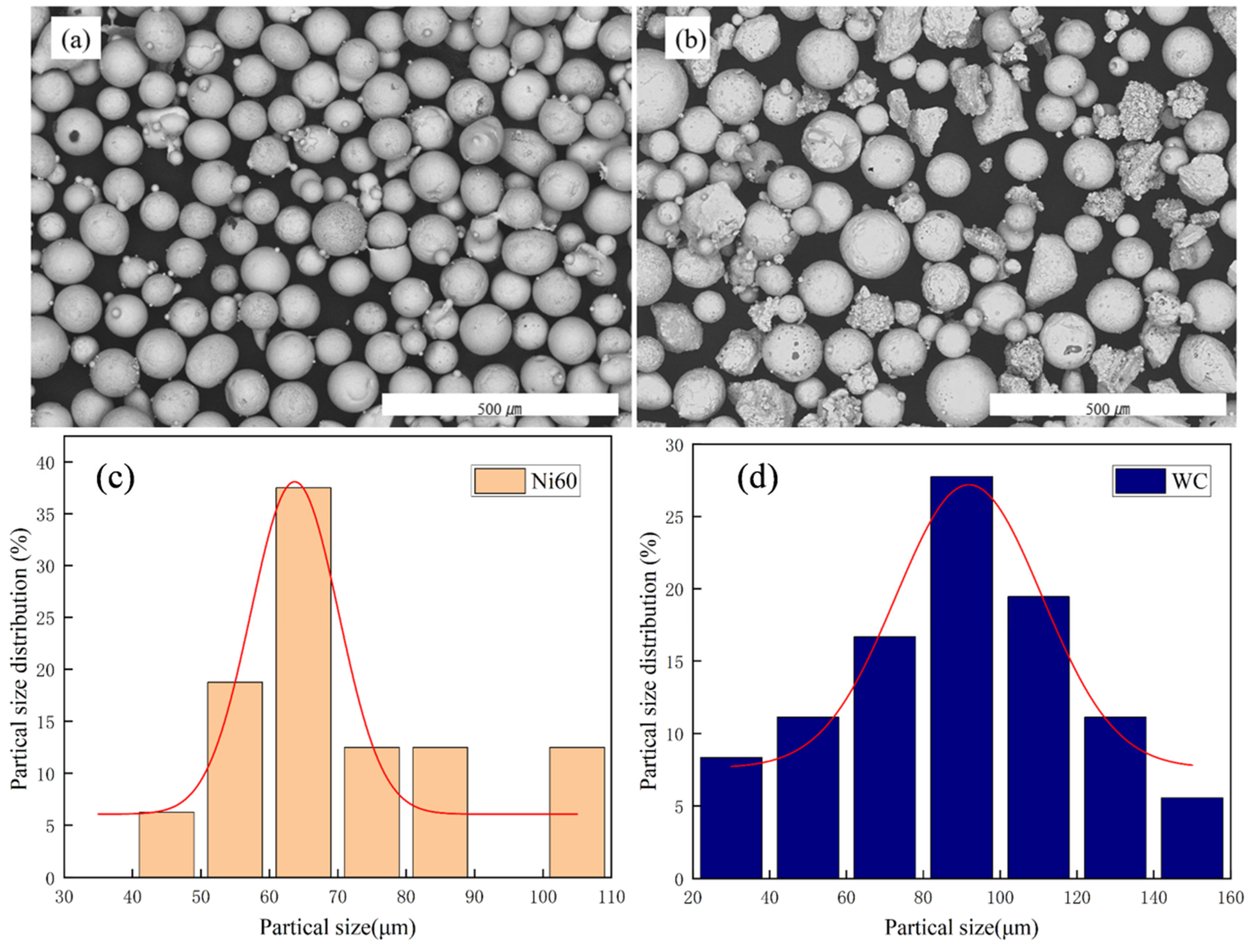
2.1. Experimental Materials

The experimental substrate was Q235 carbon steel plate with a size of 50 mm × 100 mm × 3 mm. The surface of the substrate was sanded with 400 mesh and 800 mesh sandpaper to remove the stains and oxidation layer, and the coating material was Ni60 (70%) + WC (30%). The chemical compositions of the Ni60 alloy powder and WC powder are shown in Figure 1. The size of the Ni60 alloy powder ranged from 41 to 107 μm, with an average of 71 μm, and the size of the WC powder ranged from 26 to 154 μm, with an average of 87 μm. (See Table 1).

2.2. Experimental Equipment

In this experiment, the XL-F2000T laser was used as the equipment for the laser cladding experiment. The surface morphology of the experimental samples was observed and photographed using a Hitachi TM4000Plus (Hitachi High-Technologies, Osaka, Japan) scanning electron microscope (SEM) after grinding and processing. This helped us to obtain the microstructural properties of the coating. The distribution of the elements in the coating was analyzed qualitatively and quantitatively with the aid of energy-dispersive (X-ray) spectroscopy (EDS). In addition, in order to study the hardness variation among the coatings, MHVD-1000AT (Shanghai Polycrystalline Precision Instrument Manufacturing Co., Ltd., Shanghai, China) hardness testing equipment was used to measure the hardness of the cross-section of the coated specimens. In this study, the hardness value of each specimen was tested from the surface of the cladding layer to the substrate. The applied load was set to 1.96 N, and the loading time was set to 10 s. Firstly, 7 points were tested from the cladding layer to the substrate in the longitudinal direction, with spacings of 0.2 mm in the cladding layer test and 0.1mm in the substrate test. Another 7 points were tested in the transversal direction at the left and right sides, with a spacing of 0.1 mm. A curve of the hardness variation was plotted based on the hardness values tested. The XRD-6100 (Shimadzu, Tokyo, Japan) X-ray diffractometer (XRD) was used to study the physical compositions of the coatings. The diffraction scanning interval was set from 10 to 90 degrees, the scanning step was 0.04 degrees, and the scanning speed was 6°/min. The CS Studio (Wuhan Corrtest Instruments CORP., Ltd., Wuhan, China) electrochemical workstation was used to characterize the corrosion resistance of the samples. Considering that seawater mainly contains a large amount of NaCl and a small amount of other salts, the corrosive medium was set to a 0.035 mass fraction NaCl solution to simulate the corrosive environment of seawater, so as to avoid the introduction of other interferences, which would cause uncertainty of the corrosive factors. First, the electrode system was processed before the electrochemical testing using a three-electrode electrochemical cell as the working electrode for the coated specimen, an auxiliary electrode for the platinum sheet, and a reference electrode for the saturated calomel electrode (SCE). The scan rate value was set to 0.5 mV/S, and the sampling frequency was 1 HZ. The polarization curves were obtained by calculating the experimentally measured data, and the corrosion potentials and corrosion currents of each sample were observed according to the polarization curves to assess the corrosion resistance of the materials [10].

2.3. Test Method

First, the appropriate laser melting parameters were determined through the preliminary test: 1400 W of laser power, scanning speed of 800 mm/min, spot diameter of 1.2, and defocusing amount of 3 mm. Secondly, remelting was carried out after the melting was completed. Since the energy provided by the laser power is the direct cause of changing the properties of the cladding layer, the laser remelting power was set to 1200 W, 1400 W, and 1600 W with the scanning speed unchanged. At the end of the experiment, two 10 mm × 10 mm samples were prepared using the wire cutting machine for microscopic observation and electrochemical analysis.
In order to prepare the metallographic specimens, the cross-section was repeatedly polished with 800 mesh, 1200 mesh, and 2000 mesh sandpaper, and then polished with abrasive paste and an abrasive cloth. The specimens were etched using aqua regia (V(HNO3):V(HCl) = 1:3), with an etching time of 40 s. Then, the cross-section was wiped with alcohol, and finally airdried with a hairdryer. This process can dissolve the oxides and other impurities on the surface of the metal to obtain a clear metallographic structure convenient for microscope observation.

3. Results and Discussion

Regarding the macroscopic morphology of the coatings, they were rough without remelting and smoother after remelting. Physical phase analysis showed that there were obvious crystal peaks on the surface of the fused cladding layer when it was not remelted, such as solid solution γ-(Fe,Ni), carbide M23C6, M7C, etc. After remelting power, there was little change in the organization; only the solid solution γ-(Fe,Ni), M23C6 peaks were stronger and new phases were generated, and with the increase in the remelting power, the diffraction peaks were more obvious. The scanning electron microscope (SEM) micrographs show that the WC particles in the cross-section of the non-remelted cladding layer were relatively intact, with little reticulated eutectic organization, and that an increase in the remelting power caused the WC particles to decrease, rupture, and decompose. The results of the hardness experiments show that the interface of the non-remelted coating fluctuated greatly, and the hardness of the remelted layer did not change significantly at a laser power of 1200 W. The hardness of the cross-section of the fused cladding layer was a little lower at 1400 W, but stable, and the microhardness decreased at 1600 W and was the most stable. The electrochemistry results showed that the self-corrosion potential of the coating at a remelting power of 1600 W was Ecorr = 0.0284 V, which was larger than that of the other coatings, and the self-corrosion current density of Icorr = 2.397 × 10⁻⁵ A/cm2 was the smallest, with the best corrosion resistance.

3.1. Coating Macro-Morphology

In Figure 2, the macroscopic morphology of the coating before and after remelting is shown, where (a) is the macroscopic morphology of the coating without remelting, and (b, c, d) are the macroscopic morphologies of the coating after remelting with three different powers, namely 1200 W, 1400 W, and 1600 W. The surface of the non-remelted coating showed microcracks and was rough. Before remelting, the surface of the coating showed microcracks, while the non-remelted coating was rough. After the remelting treatment, the coating became smoother. It was observed that the remelted layer was thinner in the center and thicker around the surface compared to the non-remelted coating. This phenomenon is attributed to the formation of a melt pool when the cladding was remelted at different powers, which spread out in all directions under the influence of gravity. It is worth noting that the middle part of the remelted layer appeared to be thinner due to the fact that no new powder material was added inside the coating.

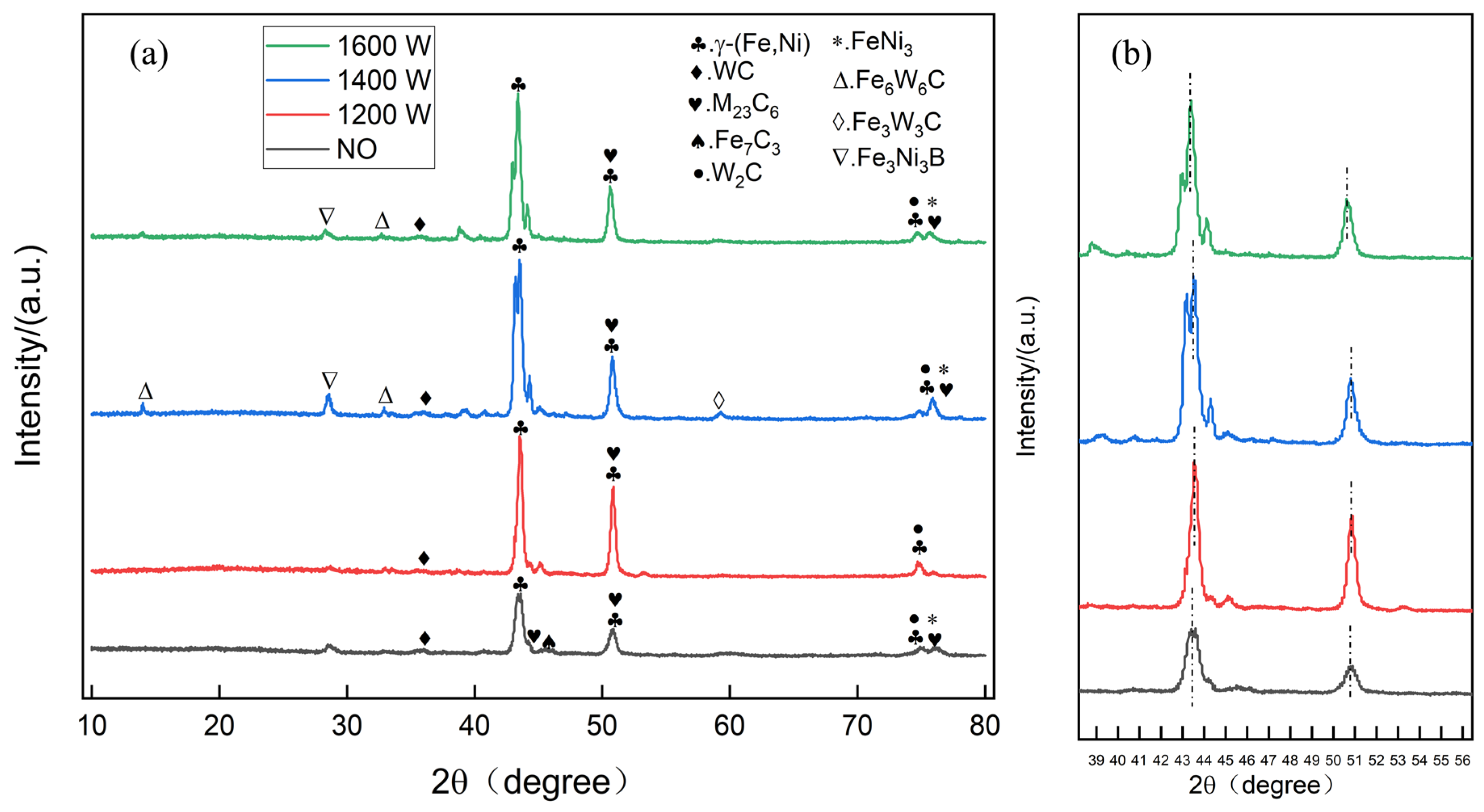
3.2. Physical Phase Analysis of the Coating

The results of X-ray diffraction of the laser cladding and remelted layer at different powers are shown in Figure 3.
As shown in Figure 3a, the crystal structure and compound composition of the fused cladding were determined with X-ray diffraction analysis to understand its properties and characteristics. In the absence of remelting, the surface of the fused cladding layer showed obvious crystal peaks, which mainly included solid solution γ-(Fe,Ni) (PDF#:26-0790), carbides M23C6 (PDF#:12-0570), and M7C3 (PDF#:05-0720) [11]. The presence of these components indicates that the fused cladding layer had a certain degree of hardness and wear resistance. At a remelting power of 1200 W, the generated organization was almost unchanged from the original fused cladding, except that the solid solution γ-(Fe,Ni) (PDF#:26-0790) and M23C6 (PDF#:12-0570) peaks were more enhanced. After remelting at 1400 W, more compounds were generated, such as Fe6W6C (PDF#:23-1127), Fe3W3C (PDF#:41-1351), Fe3Ni3B (PDF#:36-0979), etc. These compounds were able to improve the surface hardness. The type and amount of formed carbides depends on a variety of factors, including laser power, heating time, cooling rate, and so on. This may be due to the increase in laser power and longer heating time, which leads to the faster diffusion of carbon atoms and more carbon atoms combining with iron atoms to form Fe6W6C (PDF#:23-1127) carbides [12].
The cooling rate may also affect the formation of carbides. Faster cooling rates favor the formation of small-sized carbide particles, while slower cooling rates may lead to the formation of large-sized carbide particles. After remelting at 1600 W, the carbide peaks weakened, and the solid solution γ-(Fe,Ni) (PDF#:26-0790) peaks were the strongest. These results indicate that the organizational structure and compound composition of the fused cladding layer changed significantly at different remelting powers. This process may lead to the decomposition and recombination of the compounds in the fused cladding layer, thus affecting its surface hardness and properties.
Therefore, when preparing the fused cladding layer, suitable remelting parameters need to be selected according to the desired properties and application practice to ensure that the fused cladding layer has good hardness and wear and corrosion resistance [13].
As shown in Figure 3b, the main diffraction peaks of the coating significantly shifted to the right and peaked higher when the remelting power was 1200 W. This phenomenon indicates that at this power, the remelting of the material increased, leading to a phase transition or reorganization of the crystal structure. The coating may have undergone a milder heating and recrystallization process. The original crystal defects were significantly repaired and the grains grew, creating more structural order. This process may result in some degree of lattice expansion or contraction of certain phases in the coating (e.g., an Ni-based solid solution), which alters the grain spacing [14]. According to Bragg’s Law (Bragg’s Equation), changes in the crystal plane spacing can directly lead to shifts in the diffraction peaks [15]. In addition, the lower power may have promoted uniform grain growth and phase purification, resulting in an increase in the intensity of the major diffraction peaks [16].
When the remelting power was increased to 1400 W, the M23C6 peak on the right side of the diffraction peak was significantly enhanced. This indicates that as the power continued to increase, more tungsten carbide phase (WC) began to participate in the reaction, forming the M23C6 phase. This process may be attributed to the laser energy that makes the local temperature increase, which promotes the reaction and transformation of the WC phase to increase its content in the material.
At a higher laser remelting power (e.g., 1600 W), the coating underwent a more intense heating and melting process. Such processes may lead to further grain refinement or phase changes (e.g., solid solution decomposition, new phase generation, etc.) in the coating. Grain refinement reduces the crystal plane spacing, while phase transformation may change the crystal structure of the phase, both of which result in a leftward shift of the diffraction peaks [17]. In addition, rapid cooling at high temperatures may also cause lattice distortion or residual stress generation, which may also have an effect on the position of the diffraction peaks [18].

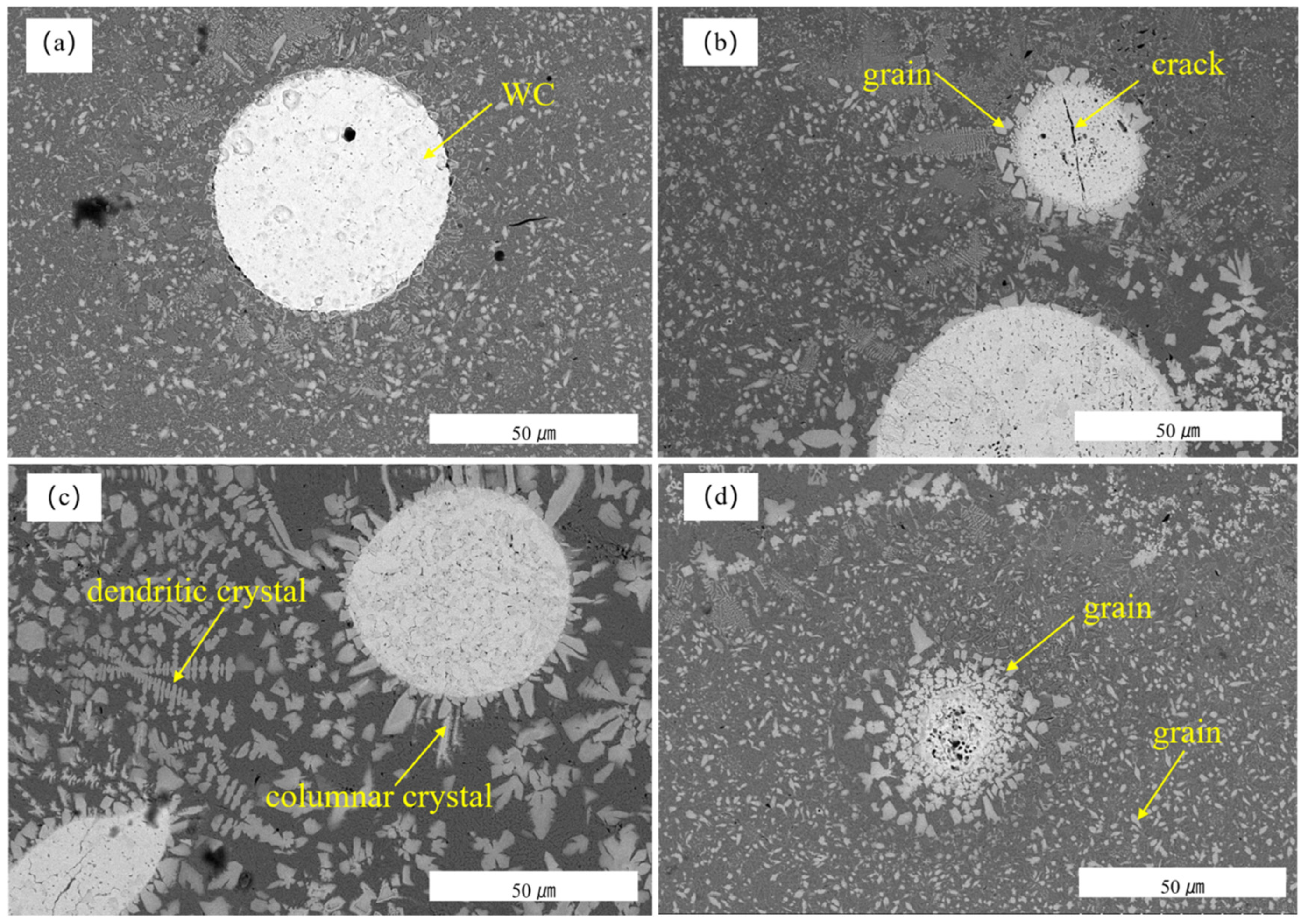
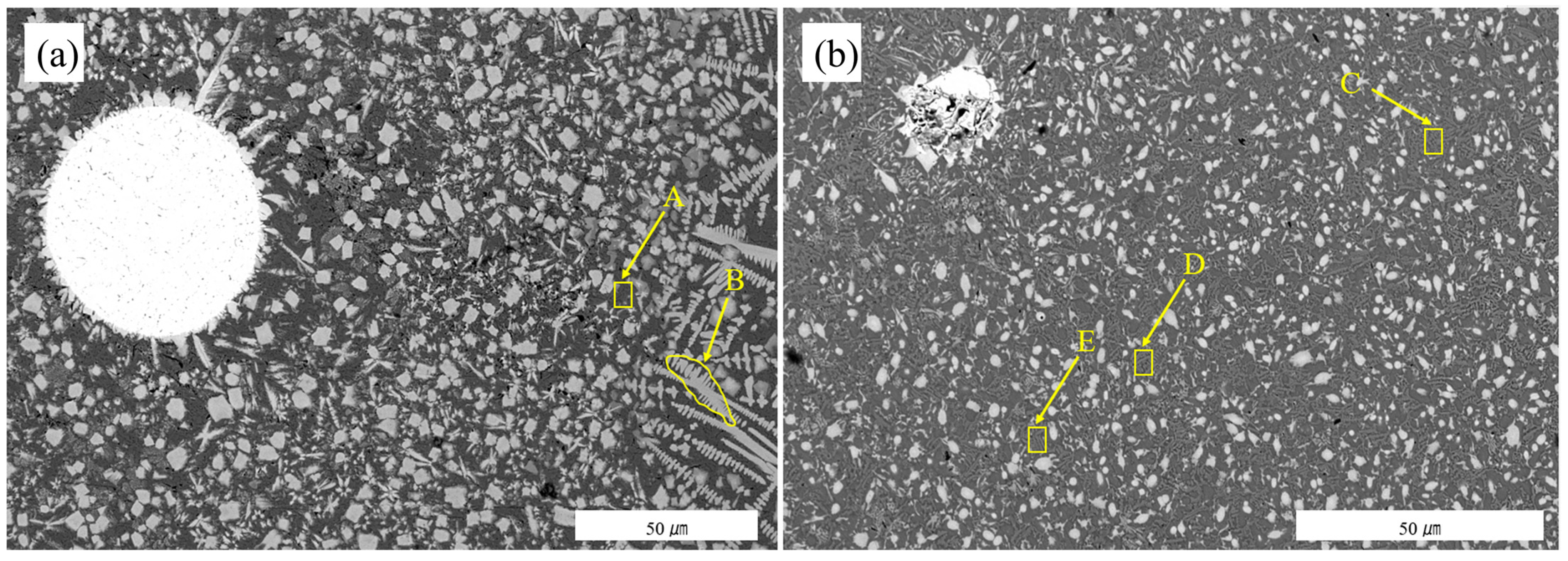
3.3. Scanning Microscopy Analysis

Figure 4 shows the cross-sectional microstructure of the remelted layer under different powers. In the cross-sectional microstructures in Figure 4, we can clearly observe the microstructural changes in the remelted layer under different powers. These changes were due to the different energy influences on the WC particles and Ni-based powders under different powers, resulting in changes in their structure and morphology. These results are important references for further optimization of the remelting process.
First, in the cross-section of the fused cladding layer without remelting, the WC particles were relatively more intact, as shown in Figure 4a, while the reticular eutectic organization was lower. This is consistent with the trend of the XRD diffraction peak in Figure 3. This is because without the remelting process, the WC particles were not subjected to too much thermal energy and thus maintained a relatively intact structure [19].
However, when the laser power was increased to 1200 W, as shown in Figure 4b, cracks began to appear in the WC particles, and triangular, quadrilateral, or other irregularly shaped fragments appeared around the WC boundaries. In addition, the formation of a reticulated eutectic organization was also observed. This is due to the fact that more energy was absorbed by the WC particles during power remelting, which led to the decomposition of their structure and the diffusion of C and W elements to react with the elements in the nickel base alloy to form compounds.
When the laser power was increased to 1400 W, as shown in Figure 4c, a large number of dendrites appeared in the fused layer and columnar or peaked crystals appeared around the WC particles, which had a certain directionality, with the direction perpendicular to the boundary of the WC particles radiating outward. This is due to the fact that the WC particles were subjected to stronger thermal energy at a high power, which led to the formation of crystals and changes in directionality. At high temperatures, WC reacts with elements of Ni60 in the melt pool to produce new phases with specific crystal structures (e.g., MyCx) [20]. At the same time, high-power laser energy can promote increases in WC rupture, the decomposition of small-particle nucleation plasmas, and the rapid solidification of the melt pool, leading to the refinement of the microstructure [21,22]. In addition, the inhomogeneous distribution of WC particles may lead to localized differences in the chemical composition and temperature, thus causing local changes in the crystal structure and growth direction [23].
When the laser power was increased to 1600 W, the WC particles broke up and decomposed into smaller fragments that were evenly distributed across the coating cross-section. This is due to the fact that in the molten pool, the WC particles started to move from their initial position in the presence of liquid metal and carbide. Subsequently, due to the penetration of liquid metal and laser radiation, large-scale rupture of the WC particles occurred, as shown in Figure 4d. The WC particles may rupture at high temperatures and form fragments. These fragments are present in the composite layer and can act as nuclei or obstacles to hinder grain growth [24]; the molten composite powder cools rapidly to form a rapidly solidifying composite layer. The high cooling rate helps to inhibit grain growth, resulting in a smaller grain size. Fine grains increase the number of grain boundaries, which enhances the strength and hardness of the material. In addition, fine grains can also increase the anion barrier effect of the coating [25]. WC grains can be refined, and the fine grains can form more grain boundaries. The defects and interfaces on the grain boundaries can effectively block the diffusion of anions, which improves the barrier properties of the coating [10,26]. This is due to the higher-power laser irradiation leading to higher heat input and a faster cooling rate. High-power laser irradiation causes WC particles to absorb more energy, which leads to rapid melting and rupture. During the melting process, the WC particles interact with the liquid nickel base alloy, producing a large amount of carbon and tungsten elements to be dissolved in the liquid metal. Subsequently, during fast cooling, these dissolved carbon and tungsten elements react with other elements in the melt pool to form new grains. Due to the fast cooling rate, the grains do not have enough time to grow, resulting in finer grain sizes.
During the formation of the fusion coating, the WC microstructure underwent a series of evolutionary processes, as shown in Figure 5. At first, the WC particles remained relatively intact in the non-remelted fusion-coated layer. With the gradual increase in the laser remelting power, the WC particles underwent significant changes. This process shows the evolution of the WC microstructure under different laser powers, which provides an important reference for the coating formation mechanism.
Figure 6a and Table 2 demonstrate the cross-sectional morphology of the remelted coating and its EDS elemental distribution at a laser power of 1400 W. The EDS elemental distribution of the remelted coatings is shown in Figure 6b and Table 2. When the laser power was remelted at 1400 W, the process was characterized by the further rupture of the WC particles, the further diffusion of elements such as Ni, Fe, and W, and faster crystal growth due to the temperature gradient and solute concentration gradient during the cooling process of the molten pool. Under the effect of these factors, Fe and W atoms combined to form dendrites. Combined with the atomic percentages of the spectral data shown in Table 2, the atomic ratio of 9.90% Cr and 1.99% C in the A region of the figure was close to 23:6, indicating that there was a mixture of Cr23C6 compounds in the organization. Figure 6 shows that the atomic ratio of 2.85% C, 15.23% Fe, and 14.32% W in the B region was close to 1:6:6, indicating that the dendrites here are Fe6W6C.
Figure 6b and Table 3 demonstrate the cross-sectional morphology of the remelted coating at a laser power of 1600 W and its EDS elemental distribution. In the range of the C area, the atomic ratio of Fe and Ni was close to 1:1, and it can be inferred that this was mainly a solid solution (Ni,Fe). In the table, it can be seen that in the D and E position regions, the atomic ratio of Fe to Ni was also close to 1:1; thus, again, a solid solution (Ni,Fe) was predominant. The formation of this structure helps to enhance the densification of the coating, thus improving its corrosion resistance. The percentages of the tungsten elements in the three regions of C, D, and E were 6.20%, 6.32%, and 8.13%, respectively, with little difference and uniform distribution in the coating. When the laser power was 1600 W, the WC particles melted and decomposed, and the small particles hindered the crystal growth. When the molten pool exists for a longer period of time, W elements are more likely to diffuse. The higher melting point of the W elements makes them solidify first, hindering crystal growth, and the crystal grains are refined. This uniform distribution of elements and fine crystals is important for the performance enhancement of the coatings. Further research will help to gain a deeper understanding of its potential application in the field of corrosion resistance.

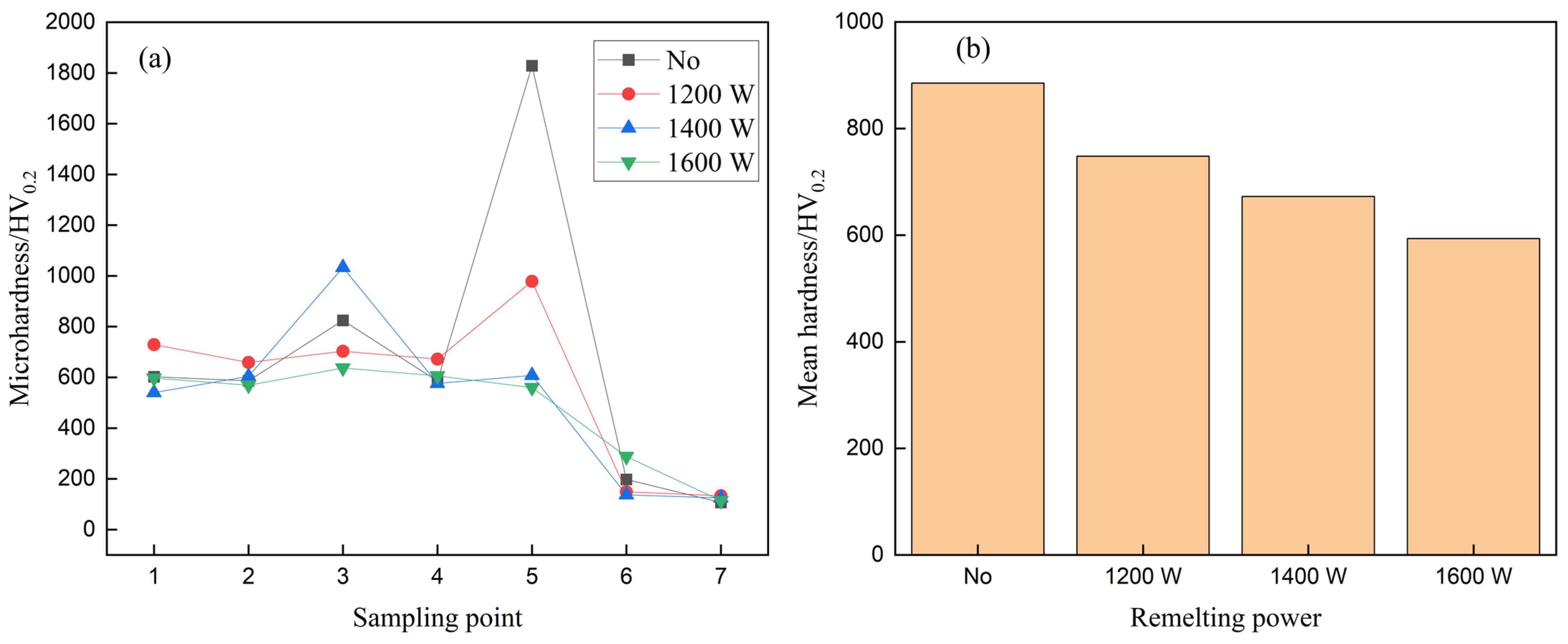
3.4. Hardness Analysis

Figure 7 shows four different power remelting coating hardness change curves. In the figure, it can be seen that the hardnesses of the fused cladding layer and the remelted layer had obvious differences. The hardness of the fused cladding layer without remelting fluctuated greatly, while the hardness of the remelted fused cladding layer was relatively more uniform. The average hardness of the fused cladding layer without remelting was 885.3 HV, which is due to the fact that more intact WC particles in the fused cladding layer were not melted, resulting in high hardness in some areas, which improved the average hardness. The standard deviation of the coating without remelting reached 537. The hardness of the cladding layer remelted at 1200 W was 748.2 HV, and the hardness fluctuated from the surface of the cladding layer to the substrate at various points. The hardness of the most obvious position of the fifth point was strangely high, reaching more than 1800 HV, which was due to the detection point just on the WC particles [27]. The hardness of the cladding layer remelted at 1400 W was 672.4 HV, and the hardness of the first point can be seen to be lower than that of the other points in the figure. It can be seen that the hardness of the first point was lower than the other coatings, which was due to the coarse grains generated at the first point, weakening the strengthening effect of the WC on the composite coating. The average hardness of the fused cladding layer remelted at a power of 1600 W was 593.7 HV, and the microhardness of the heat-affected zone also increased with the increase in remelting power [12]. The hardnesses were all much higher than the hardness of the base material Q235 steel. The hardness of the remelted layer was lower than that of the cladding layer, and the standard deviation of the microhardnesses of the remelted layers under different powers were 132, 203, and 31, in that order. With the increase in remelting laser power, the average hardness of the cladding layer decreased and was more uniformly distributed. This was due to the more uniform distribution of the melted fragments of WC particles in the cladding layer and the generation of more solid solution γ-(Fe,Ni), which significantly reduced the number of precipitated carbides. Solid solution γ-(Fe,Ni) itself also has a lower hardness [28].

3.5. Analysis of Corrosion Resistance of Fused Cladding Layer before and after Remelting

Figure 8 shows the polarization Tafel curves of the fused cladding and remelted layers with different powers in the solution containing 3.5% NaCl, and the parameters of the self-corrosion potential and current density of each specimen are shown in Table 4. The self-corrosion potential Ecorr is the probability of the fused cladding layer to be corroded; the more positive the value is, the lower the probability of corrosion occurring [29]. The self-corrosion current density Icorr reflects the corrosion rate of the material, and the smaller the value of Icorr, the slower the corrosion rate [10,30].
Comparing the polarization curves of the fused and remelted layers in Figure 8, it can be seen that the self-corrosion potential Ecorr = 0.0284 V of the coating at the remelting power of 1600W was greater than that of the other coatings. This sample had the largest self-corrosion potential and the smallest self-corrosion current density, Icorr = 2.397 × 10⁻⁵ A/cm2.
No remelting occurred when the self-corrosion potential was −0.0392 V, the self-corrosion current density was 8.108 × 10⁻⁴ A/cm2, the coating WC particles were more complete compared to those more and less fused, and the formation of the substrate of the primary cell was more obvious.
When the laser power was 1200 W, and the self-corrosion potential was −0.0322 V, the difference was very small, only 0.007 V. The self-corrosion current density also showed almost no difference; this is because there was no remelting when the laser power was 1200 W. In Figure 3, according to the XRD, it can be seen that the two coatings had almost the same physical phase.
When the laser power was 1400 W, the self-corrosion potential was −0.0669 V. Compared to the other coatings, it was the smallest; this is because more WC melting leads to the decomposition and diffusion of W and C to form a C element-enriched area and thus a Cr-rich carbide, Cr23C6, which further reduces the content of Cr. The Cr content near the grain boundary is reduced, and the electrode potential is reduced, which leads to intergranular corrosion [10,31,32].
When the laser power was 1600 W, the self-corrosion potential of 0.0284 V was the largest compared to the other coatings. The molten pool existed for a relatively long time, which generated more solid solutions (Ni, Fe). The W element diffused more uniformly compared to the other coatings, which hindered the growth of carbides and generated more fine eutectic compounds. The refinement of the grain improving the corrosion resistance of the material is mainly due to the increase in the surface area of the material, which promotes the enhancement of corrosion resistance. The crystalline boundaries between the grains effectively prevent erosion of the corrosive medium, thus slowing down the corrosion rate of the material. Fine grains also help to hinder the propagation of corrosion cracks, increasing the durability of the material. In addition, the uniform distribution of Cr in the nickel base and the formation of the Cr2O3 passivation film increased the self-corrosion potential and slowed down the surface corrosion rate, thus increasing the corrosion resistance of the coating [33,34].

4. Conclusions

  • Remelting treatments affect the macroscopic morphology, microstructure, and coating properties of WC/Ni-based fused cladding layers at different laser powers. Experiments showed that the remelting of coatings at different laser powers did not always have a positive effect on the coating properties. In the coatings, the main phases include (Ni, Fe) solid solutions, WC/W2C ceramic particles, and MC carbides. When remelted at powers greater than 1400 W, new phases, Fe6W6C and Fe3W3C, were formed in the coating.
  • When the laser power was 1200 W, the dissolution of ceramic particles in the WC remelted layer did not change significantly relative to the non-remelted coating. When the laser power was 1400 W, the ceramic particles in the WC coating were partially dissolved, the (Ni, Fe) dendrites and MC carbides increased, and the internal uniformity of the coating began to increase. The surface hardness of the fused coating was lower than that of the other remelted layers. When the laser power was 1600 W, the WC particles decreased and more solid solution was generated, which decreased the microhardness but increased the smoothness of the coating surface.
  • When the laser power was 1600 W, the self-corrosion potential of 0.0284 V was the largest relative to the other remelted layers, and the self-corrosion current density of 2.397 × 10⁻⁵ A/cm2 was the smallest relative to the other remelted layers, so the corrosion resistance was the best.

Author Contributions

Conceptualization, W.S. and J.H.; methodology, J.W.; software, X.W.; validation, J.H., X.W., J.C. and W.S.; formal analysis, X.W.; investigation, X.W and Q.W.; resources, W.S. and J.H.; data curation, J.W.; writing—original draft preparation, X.W.; writing—review and editing, X.W. and J.H.; visualization, J.W.; supervision, F.A. and Q.W.; project administration, W.S.; funding acquisition, J.W and Q.W. All authors have read and agreed to the published version of the manuscript.

Funding

Supported by the National Natural Science Foundation Project (No. 62073089), the Zhanjiang Science and Technology Plan Project (No. 2021A05171), and the Laser Processing Team Project of Guangdong Ocean University (No. CCTD201823).

Institutional Review Board Statement

Not applicable.

Informed Consent Statement

Not applicable.

Data Availability Statement

Data are contained within the article.

Conflicts of Interest

The authors declare no conflicts of interest.

References

  1. Liang, Y.; Liao, Z.Y.; Zhang, L.L.; Cai, M.W.; Wei, X.S.; Shen, J. A review on coatings deposited by extreme high-speed laser cladding: Processes, materials, and properties. Opt. Laser Technol. 2023, 164, 109472. [Google Scholar] [CrossRef]
  2. Wan, M.Q.; Shi, J.; Lei, L.; Cui, Z.Y.; Wang, H.L.; Wang, X. A comparative study of the microstructure, mechanical properties and corrosion resistance of Ni-or Fe-based composite coatings by laser cladding. J. Mater. Eng. Perform. 2018, 27, 2844–2854. [Google Scholar] [CrossRef]
  3. Li, Y.; Shi, Y.; Jiang, G.; Tang, S.; Wu, J.; Wang, J. Effect of WC on microstructure, molten pool and properties of Ni based coatings by multi-layer laser cladding. Opt. Laser Technol. 2024, 174, 110612. [Google Scholar] [CrossRef]
  4. Chen, G.D.; Liu, X.B.; Zhang, F.Z.; Liu, Q.S.; Ou, H.Z.; Zhang, S.H. Fabrication and tribological properties of laser cladding WC-Cu/Co-based composite coatings. Surf. Coat. Technol. 2023, 472, 129930. [Google Scholar] [CrossRef]
  5. Cheng, H.; Fang, Z.G.; Dai, S.; Zhao, X.R.; Yi, J. Microstructure and properties of laser cladding Co-based alloy coatings. Adv. Mater. Res. 2011, 295, 1665–1668. [Google Scholar] [CrossRef]
  6. Hu, Z.; Li, Y.; Lu, B.; Tan, N.; Cai, L.; Yong, Q. Effect of WC content on microstructure and properties of high-speed laser cladding Ni-based coating. Opt. Laser Technol. 2022, 155, 108449. [Google Scholar] [CrossRef]
  7. Lei, J.; Shi, C.; Zhou, S.; Gu, Z.; Zhang, L.-C. Enhanced corrosion and wear resistance properties of carbon fiber reinforced Ni-based composite coating by laser cladding. Surf. Coat. Technol. 2018, 334, 274–285. [Google Scholar] [CrossRef]
  8. Liu, L.; Wang, D.; Deng, G.; Han, C.; Zhou, H.; Tan, C.; Long, Y.; Liu, Z.; Zhang, M.; Yang, C.; et al. Crack inhibition and mechanical property enhancement of a CM247LC alloy fabricated by laser powder bed fusion through remelting strategy. Mater. Charact. 2024, 214, 114073. [Google Scholar] [CrossRef]
  9. Zeng, Z.; Shang, J.; Lin, D. Effect of laser remelting power on the microstructure and properties of vanadizing layer on AISI 52100 steel pin shaft. Heliyon 2024, 10, e06729. [Google Scholar] [CrossRef]
  10. Gurappa, I. Characterization of different materials for corrosion resistance under simulated body fluid conditions. Mater. Charact. 2002, 49, 73–79. [Google Scholar] [CrossRef]
  11. Chang, W.; Gao, G.; Zhang, H.; Chen, H.; Yi, M.; Zhang, J.; Chen, Z.; Xu, C. Microstructure and properties of graphene reinforced co-based composite coating by laser cladding. Surf. Coat. Technol. 2023, 453, 129139. [Google Scholar] [CrossRef]
  12. Li, J.; Yang, Y.; Yao, F.; Zheng, F. Effect of laser remelting on internal defects and properties of Ni-based coatings reinforced by multi-channel WC in situ. Mater. Today Commun. 2024, 38, 108375. [Google Scholar] [CrossRef]
  13. Yang, Y.; Li, J.; Yao, F.; Li, X. Effect of laser remelting on the organization and properties of WC/Ni-based coatings generated in situ by laser cladding. J. Manuf. Process. 2023, 102, 501–512. [Google Scholar] [CrossRef]
  14. Li, K.; Li, D.; Liu, D.; Pei, G.; Sun, L. Microstructure evolution and mechanical properties of multiple-layer laser cladding coating of 308L stainless steel. Appl. Surf. Sci. 2015, 340, 143–150. [Google Scholar] [CrossRef]
  15. Blake, A.J.; Cole, J.M.; Evans, J.S.; Main, P.; Parsons, S.; Watkin, D.J. Crystal Structure Analysis: Principles and Practice; OUP Oxford: Oxford, UK, 2009; Volume 13. [Google Scholar]
  16. Weng, F.; Yu, H.; Chen, C.; Liu, J.; Zhao, L.; Dai, J.; Zhao, Z. Effect of process parameters on the microstructure evolution and wear property of the laser cladding coatings on Ti-6Al-4V alloy. J. Alloys Compd. 2017, 692, 989–996. [Google Scholar] [CrossRef]
  17. Al-Qawabah, S.M.; Zaid, A.I. Different methods for grain refinement of materials. Int. J. Sci. Eng. Res. 2016, 7, 1133–1140. [Google Scholar]
  18. Ortiz, A.L.; Tian, J.W.; Villegas, J.C.; Shaw, L.L.; Liaw, P.K. Interrogation of the microstructure and residual stress of a nickel-base alloy subjected to surface severe plastic deformation. Acta Mater. 2008, 56, 413–426. [Google Scholar] [CrossRef]
  19. Shen, X.; Ma, S.; He, X.; Zhang, J.; Ma, X.; Yin, Y.; Pan, S.; Wei, F. Quality enhancement of crack-free laser-cladded NiCrSiBC-WC coating by in-situ temperature field assistance (ITFA) and post-laser remelting (PLR). Surf. Coat. Technol. 2024, 484, 130873. [Google Scholar] [CrossRef]
  20. Chen, C.; Feng, A.; Wei, Y.; Wang, Y.; Pan, X.; Song, X. Effects of WC particles on microstructure and wear behavior of laser cladding Ni60 composite coatings. Opt. Laser Technol. 2023, 163, 109425. [Google Scholar] [CrossRef]
  21. Meng, L.; Zhu, B.; Liu, X.; Zeng, X. Investigation on the Ni60-WC composite coatings deposited by extreme-high-speed laser-induction hybrid cladding technology: Forming characteristics, microstructure and wear behaviors. Surf. Coat. Technol. 2023, 473, 130033. [Google Scholar] [CrossRef]
  22. Chen, C.; Feng, A.; Wei, Y.; Wang, Y.; Pan, X.; Song, X. Effect of multiple laser shock peening on the microstructure and properties of laser cladding nano-WC/Ni60 composite coatings. Opt. Laser Technol. 2023, 167, 109719. [Google Scholar] [CrossRef]
  23. Li, W.; Yang, X.; Wang, S.; Duan, D.; Li, F.; Qiao, Y.; Liu, Y.; Liu, X. The effect of WC content on the bonding strength and mechanical properties of WC/Ni60 coatings of brake disc. Opt. Laser Technol. 2022, 149, 107822. [Google Scholar] [CrossRef]
  24. Li, C.; Zhang, Q.; Wang, F.; Deng, P.; Lu, Q.; Zhang, Y.; Li, S.; Ma, P.; Li, W.; Wang, Y. Microstructure and wear behaviors of WC-Ni coatings fabricated by laser cladding under high frequency micro-vibration. Appl. Surf. Sci. 2019, 485, 513–519. [Google Scholar] [CrossRef]
  25. Jian, Y.; Liu, Y.; Qi, H.; He, P.; Huang, G.; Huang, Z. Effects of scanning speed on the microstructure, hardness and corrosion properties of high-speed laser cladding Fe-based stainless coatings. J. Mater. Res. Technol. 2024, 29, 3380–3392. [Google Scholar] [CrossRef]
  26. Zhang, Z.; Kovacevic, R. Laser cladding of iron-based erosion resistant metal matrix composites. J. Manuf. Process. 2019, 38, 63–75. [Google Scholar] [CrossRef]
  27. Tan, N.; Hu, Z.; Zhou, Y.; Li, Y.; Lu, B.; Hu, D.; Liu, Y.; Li, Q. Effect of WC particle size on the microstructure and tribological properties of high-speed laser cladding Ni/WC composite coatings. Mater. Today Commun. 2024, 39, 109066. [Google Scholar] [CrossRef]
  28. Wang, S.; Shi, W.; Cheng, C.; Liang, F.; Li, K. Effect of process parameters on microstructure and properties of laser cladding Ni60 + 30% WC coating on Q235 steel. Materials 2023, 16, 7070. [Google Scholar] [CrossRef]
  29. Shengfeng, Z.; Gaoqin, D.; Haizhong, Z. Characteristics on structure and properties of WC-Ni60A coatings by laser cladding and laser-induction hybrid cladding. J. Mech. Eng. 2012, 48, 113–118. [Google Scholar]
  30. Luo, F.; Yang, T.; Zhao, Y.; Xiong, Z.; Huang, J. Effect of W Content on Microstructure and Properties of Laser Cladding CoCrFeNi HEA Coating. Coatings 2023, 13, 1301. [Google Scholar] [CrossRef]
  31. He, B. Effect of WC content on microstructure and properties of WC/316L laser coatings. Ferroelectrics 2023, 608, 1–2. [Google Scholar] [CrossRef]
  32. Munagala, V.N.; Wasekar, N.P.; Bathini, L.; Ramakrishna, L.; Sundararajan, G. Deciphering the role of W content, triple junctions, and heat treatment on the corrosion performance of Ni–W alloy coatings used for automotive applications. Mater. Chem. Phys. 2023, 308, 128305. [Google Scholar] [CrossRef]
  33. Tam, P.L. Tailoring of Transition Metal Silicides as Protective Thin Films on Austenitic Stainless Steel; Chalmers Tekniska Hogskola: Gothenburg, Sweden, 2011. [Google Scholar]
  34. Wu, R.; Han, Z.; Gao, B.; Zhang, Z.; Wu, P.; Shuang, Y.; Chen, H.; Liu, B. Effect of Pre-Strain on Microstructure and Corrosion Resistance of 840 Nickel Base Alloy Steel. SSRN 2024. Available online: https://ssrn.com/abstract=4629171 (accessed on 1 March 2024).
Figure 1. Powder morphology and size distribution. (a) Ni60 powder morphology distribution. (b) WC powder morphology distribution. (c) Ni60 powder size. (d) WC powder size.
Coatings 14 01172 g001
Figure 2. Macroscopic morphology of cladding layer before and after remelting. (a) Macroscopic appearance of non-remelted coating. (b) Macroscopic appearance of remelted layer at 1200 W of power. (c) Macroscopic appearance of remelted layer at 1400 W of power. (d) Macroscopic appearance of remelted layer at 1600 W of power.
Coatings 14 01172 g002
Figure 3. XRD diffraction pattern analysis. (a) Diffractograms of laser cladding layers at different levels of power. (b) Localized enlargement of diffraction patterns of laser cladding layers.
Coatings 14 01172 g003
Figure 4. Fe3W3C compounds appeared. The generation of Fe3W3C compounds not only changes the chemical composition of the coating but also has an effect on its properties, improving its hardness and wear resistance.
Coatings 14 01172 g004
Figure 5. Microstructure changes in WC under remelting using different powers.
Coatings 14 01172 g005
Figure 6. EDS analysis of the laser-remelted cross-sections. (a) Laser power of 1400 W. (b) Laser power of 1600 W.
Coatings 14 01172 g006
Figure 7. Hardness distribution of cladding layer section. (a) Cross-section hardness distribution of cladding layer. (b) Average hardnesses of remelting layers at different powers.
Coatings 14 01172 g007
Figure 8. Polarization curve.
Coatings 14 01172 g008
Table 1. Ni60 powder and Q235 chemical compositions (mass fraction, %).
ElementCCrBMnSiFePSNi
Ni600.8–1.214–163–3.5-3.5–4.014–150.020.02Bal
Q2350.22--0.3–0.70.35Bal0.0450.05-
Table 2. Non-structural composition of remelted coating at 1400 W (atomic fraction %).
AreaCOFSiCrFeNiW
A1.991.254.074.599.9024.9250.312.96
B2.852.083.006.3114.7615.2341.4514.32
Table 3. Non-structural composition of remelted coating at 1600 W (atomic fraction %).
AreaCOFSiCrFeNiW
C2.672.032.812.7111.3437.8634.386.20
D3.781.844.451.8711.2337.5132.996.32
E3.680.444.012.659.4836.3335.298.13
Table 4. Corrosion test results of samples in 3.5% NaCl solution.
SampleEcorr/VI/(A/cm2)
NO−0.03928.108 × 10−4
1200 W−0.03224.880 × 10−4
1400 W−0.06695.364 × 10−5
1600 W0.02842.397 × 10−5
Disclaimer/Publisher’s Note: The statements, opinions and data contained in all publications are solely those of the individual author(s) and contributor(s) and not of MDPI and/or the editor(s). MDPI and/or the editor(s) disclaim responsibility for any injury to people or property resulting from any ideas, methods, instructions or products referred to in the content.

