Abstract
This research aimed to investigate the effects of input power and gas flow rate on the composition, microstructure, and mechanical properties of TiZrHfNiCuCo metallic coatings. These metallic coatings were deposited on a p-type Si wafer using a direct current magnetron sputtering system with varying input powers (100–300 W) and Ar flow rates (5–20 sccm). It was observed that increasing input power and decreasing Ar flow rate led to TiZrHfNiCuCo metallic coatings with higher hardness and smoother surfaces. The experiment resulted in the formation of a metallic amorphous coating. This study describes the mechanism by which the mechanical properties of the TiZrHfNiCuCo coating change according to sputtering parameters. Based on these results, the effects of sputter variables, such as input power and gas flow rate properties, on the properties of coatings are discussed.
1. Introduction
High-entropy alloys (HEAs) represent a novel approach in alloy design, distinct from traditional alloys, by incorporating multi-principal elements. Typically composed of five or more elements in nearly equiatomic ratios, HEAs were first introduced by Cantor et al. [1] and Yeh et al. [2]. Remarkably, even with a high concentration of many elements, HEAs predominantly form simple phases, such as solid solutions and nanocrystalline or occasionally amorphous alloys, rather than complex intermetallic compounds. This phenomenon results in lower free energy and enhanced phase stability [3,4]. The variation in atomic sizes among the constituent elements generally leads to lattice distortion and sluggish diffusion [4,5,6]. Consequently, HEAs exhibit exceptional properties, including superior hardness, oxidation resistance, irradiation resistance, good corrosion resistance, and wear resistance [7,8,9,10,11,12,13,14,15]. These characteristics have spurred extensive research into their applications across diverse fields, such as structural materials, hard coatings, diffusion barriers, and energy materials [10,12,15,16,17,18,19].
Enhancing the durability of structural components can be effectively achieved through surface coating, which modifies and strengthens their mechanical and functional properties. In addition to their use as bulk structural materials, HEAs have become attractive options for coatings, thanks to their superior properties [6,16,17,18,19,20,21]. When deposited as layers on substrate surfaces, HEA coatings can significantly improve the mechanical performance of the surface, provided that the compositions and deposition parameters are appropriately selected.
In the surface coating technology, crystalline growth and even nuclear growth are inhibited, so they can be more easily reflected in the formation of an amorphous phase [2]. One of the widely used techniques for forming HEA coatings is sputtering deposition [22,23,24].
Sputtering deposition is recognized for its ability to easily control the stoichiometry of coatings by adjusting the chemical composition of the target. It also enhances the quality of coatings by regulating variables such as input power, gas flow rate, reactive gases, substrate temperature, and deposition time [25,26,27,28,29]. In addition, the atoms with momentum can quench condensation rapidly for coatings, hence minimizing concentration fluctuations in the coatings [19]. Due to the special ‘rapid quenching’ effect of the preparation method of the HEA coatings, the FCC and BCC solid-solution phases or amorphous phases are commonly fabricated [19]. Moreover, the grain size of the HEA coating is usually restrained by their thickness, so the grain size of the HEA coating is generally smaller than the HEA bulk counterparts, which results in the grain refinement strengthening, which can result in the strengthening of the mechanical properties [19,30].
In our previous study, we developed M-containing HEAs using an equiatomic substitution strategy (M=Co, Nb and Fe) [20,31]. Additionally, we achieved TiZrHfNiCuCo HEA nitride coatings with a nano-composite structure using direct current magnetron sputtering according to various deposition parameters [25]. It was found that the HEA metallic coating exhibits an amorphous structure, whereas the addition of N2 reactive gas leads to the formation of a single-phase FCC-type nanocrystalline structure in the HEA nitride coatings. Based on these results, the present study focuses on the deposition of HEA metallic coatings without the incorporation of reactive gases, such as N or O. Additionally, this study aims to expand the scope of research on TiZrHfNiCo HEA coatings by investigating the effects of magnetron sputtering parameters on the microstructure and properties.
2. Materials and Methods
The TiZrHfNiCuCo metallic coatings were deposited on p-type Si (100) single-side polished wafer substrates with resistivities of 1–10 ohm-cm using a direct current magnetron sputtering system (KCMC, Suwon-si, Republic of Korea) under high vacuum at room temperature. The Si wafer was chosen for the investigation of the morphological and mechanical properties of the metallic coatings due to its thin thickness and flat surface. The TiZrHfNiCuCo (Plansee SE, 16.6/16.6/16.6/16.6/16.6/16.7 at.%) powder target was prepared using high-purity metallic powders of Ti, Zr, Hf, Ni, Cu, and Co. The processes involved weighing, mixing, and finally cold pressing to achieve a diameter of 50.8 mm and a thickness of 6.35 mm. As a preliminary step, the p-type Si (100) substrates were ultrasonically rinsed with acetone, ethanol, and distilled water. The rotational speed of the substrate was fixed at 10 RPM to ensure the uniform deposition of the coating layer, and the initial chamber pressure reached below Pa before proceeding to the next critical phase of argon injection. Afterwards, the flow rate of high-purity argon gas (99.999%) was controlled using a mass flow controller (MFC) (Gencoa, Liverpool, UK). The applied power was controlled from 100 W to 300 W at a fixed Ar flow rate of 20 sccm. Then, the Ar flow rate was controlled from 5 sccm to 20 sccm at a fixed applied power of 300 W. In order to minimize any contamination from the target surface and ensure a reproducible target surface state, the pre-sputtering was conducted for 10 minutes at 300 W in 20 sccm before starting the deposition process. Also, specific deposition conditions, including the applied power, deposition time, and reactive gas flow rate, are listed in Table 1.

Table 1.
The deposition conditions of the TiZrHfNiCuCo metallic coatings.
An X-ray diffractometer (PANalytical/Empyreal/PC, Malvern, UK) with Cu Kα1 radiation ( (Malvern Panalytical Ltd., Malvern, UK) and a transmission electron microscope (TEM, Tecnai F20 G2, FEI) were used for phase analysis. When measuring XRD, the scan range was from 2 to . The specimen for TEM analysis was prepared via focused ion-beam thinning (FIB, Helios Nanolab 600, FEI). The thickness, microstructure, and chemical composition of the coating were analyzed using a field-emission scanning electron microscope (FE-SEM, SU-8010, Hitachi, Tokyo, Japan) with an acceleration voltage of 15 keV. Analysis of the chemical composition was conducted using an energy-dispersive X-ray spectroscope (EDS) with an acceleration voltage of 20 keV.
The surface roughness of the coatings was analyzed using the atomic force microscope (AFM, hpAFM, Nanomagnetics Instruments, Oxford, UK) in contact mode with a standard cantilever tip with a radius curvature of less than 50 nm.
Hardness measurements were conducted on a nano-indentation (NHT-X, CSM, Needham, MA, USA) system equipped with a Berkovich diamond tip. The loading window, ranging from 5 to 10mN, depending on the coating thickness, was applied. Load displacement curves were evaluated according to Oliver and Pharr [32]. The analysis process was performed several times for each sample for the reliability of the results.
3. Results and Discussion
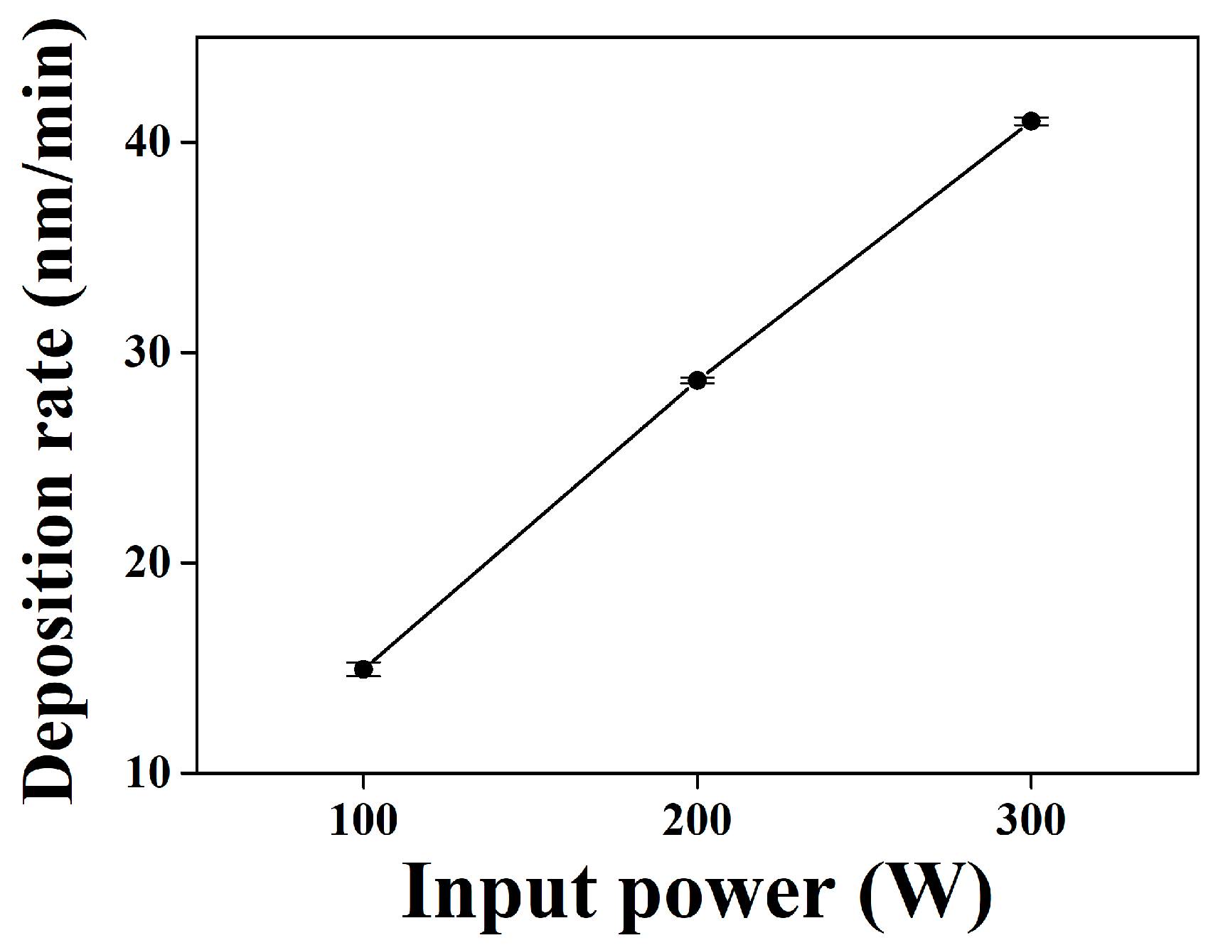
The analyses results of the process variables of DC power at 100 W, 200 W, and 300 W are shown in Figure 1 and Figure 2. Figure 1 indicates that the deposition rates ranged from 100 W to 300 W, with a constant Ar flow rate of 20 sccm. The deposition rate of TiZrHfNiCuCo coatings was calculated by dividing the thickness of the coating by the deposition time. The deposition time was 30 min, and coatings with thicknesses of approximately 472 nm, 853 nm, and 1230 nm were achieved at input powers of 100 W, 200 W, and 300 W, respectively; the deposition rates were thus about 15.7 nm/min, 28.4 nm/min, and 41 nm/min.
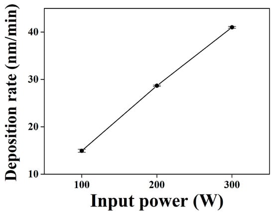
Figure 1.
Deposition rates of the TiZrHfNiCuCo coatings deposited at various input powers ranging from 100 W to 300 W, with a constant Ar flow rate of 20 sccm.
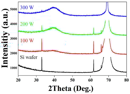
Figure 2.
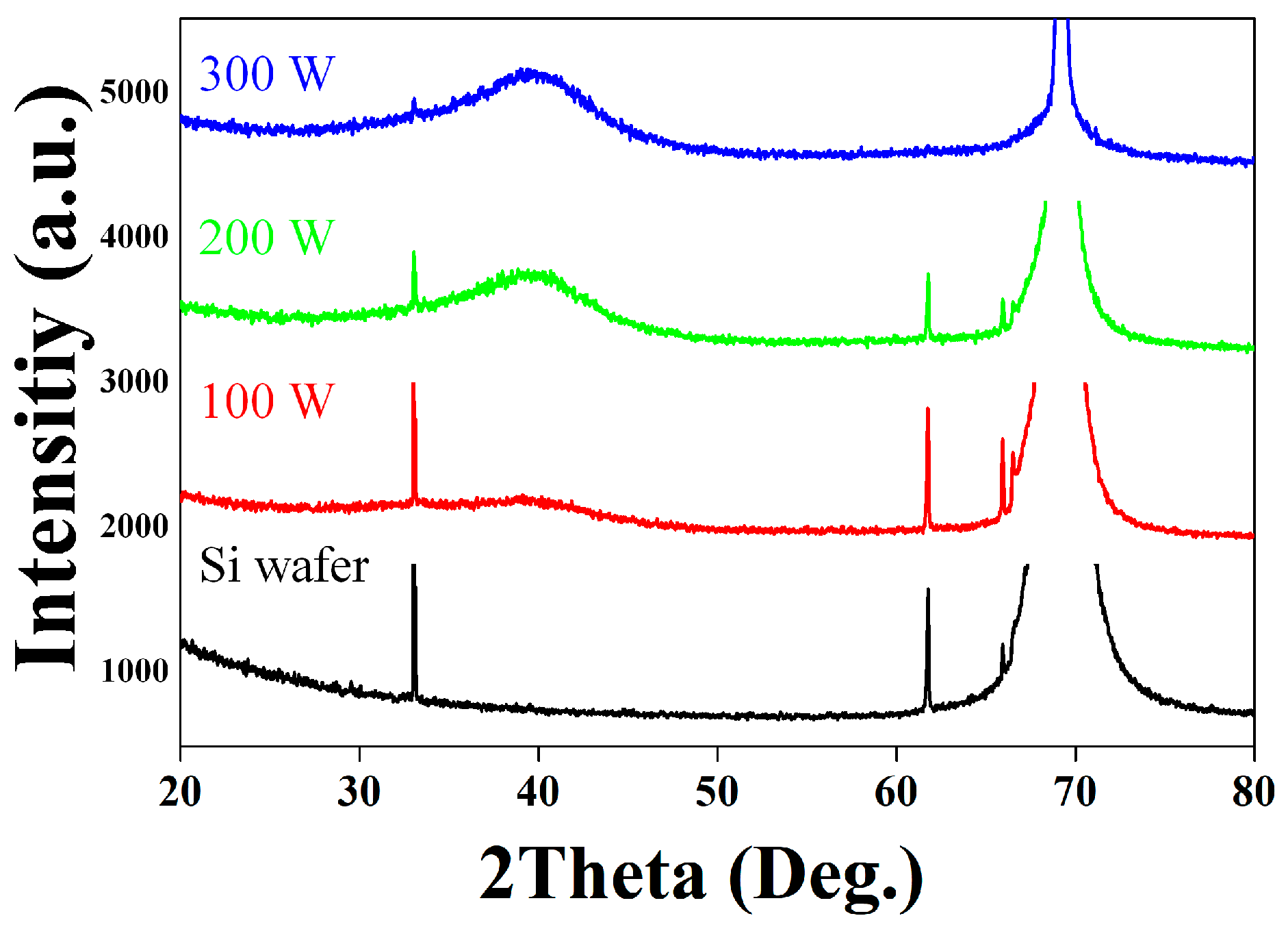
XRD diffraction patterns of a (100)-oriented p-type Si wafer substrate and the TiZrHfNiCuCo HEA metallic coatings deposited at various input powers: 100 W, 200 W, and 300 W, with a constant Ar flow rate of 20 sccm.
As input power increases while maintain a constant deposition time and Ar flow rate, the deposition rate also increases. Controlling input power affects the microstructure, particle size, and deposition structure. At low power, deposited particles act as seeds or centers of nuclei, leading to an increase in particle size, which results in a rougher surface and slower deposition rate. At a higher input power, however, target particles are physically ejected from the target and deposited quickly on the substrate, due to the acceleration of the Ar ions with the rising potential as the input power increases, resulting in faster deposition [33,34,35,36]. This phenomenon is demonstrated by the flow of the ionized particle (Jion) in the Langmuir–Child relationship and the average kinetic energy (KEav) equation in the glow discharge [37,38]. According to the Langmuir–Child relationship and the average kinetic energy equation for DC glow discharge, the flow of the ionized particle (Jion) and the average kinetic energy (KEav) impacting the substrate are dependent on the DC applied voltage. Consequently, raising the bias voltage leads to a substantial increase in the Ar ion current bombardment and the kinetic energy of the ions striking the coating surface. This enhanced bombardment significantly boosts the surface mobility of adatoms by increasing momentum transfer through collisions. These processes are directly proportional to the DC applied voltage and input power, thereby contributing to the observed increase in the sputter deposition rate [39,40].
Jion ∝ Voltage3/2,
KEav ∝ Voltage,
Figure 2 displays the XRD patterns of the as-deposited TiZrHfNiCuCo coatings on Si (100) substrates with varying sputtering input powers. The XRD result of the Si substrate is also added because of the thin thickness of the film inducing the inclusion of the structural information of the Si substrate. The difference between the diffraction peak of each coating and that of the substrate is the formation of a halo pattern in the metallic coating, centered at approximately 39. The XRD patterns suggest that each coating has an amorphous phase. Additionally, the intensity of the halo pattern increases with higher input power, attributed to the increased diffraction intensity due to the growth of the metallic coating included in the diffraction process as the metallic coating thickness increases [41].
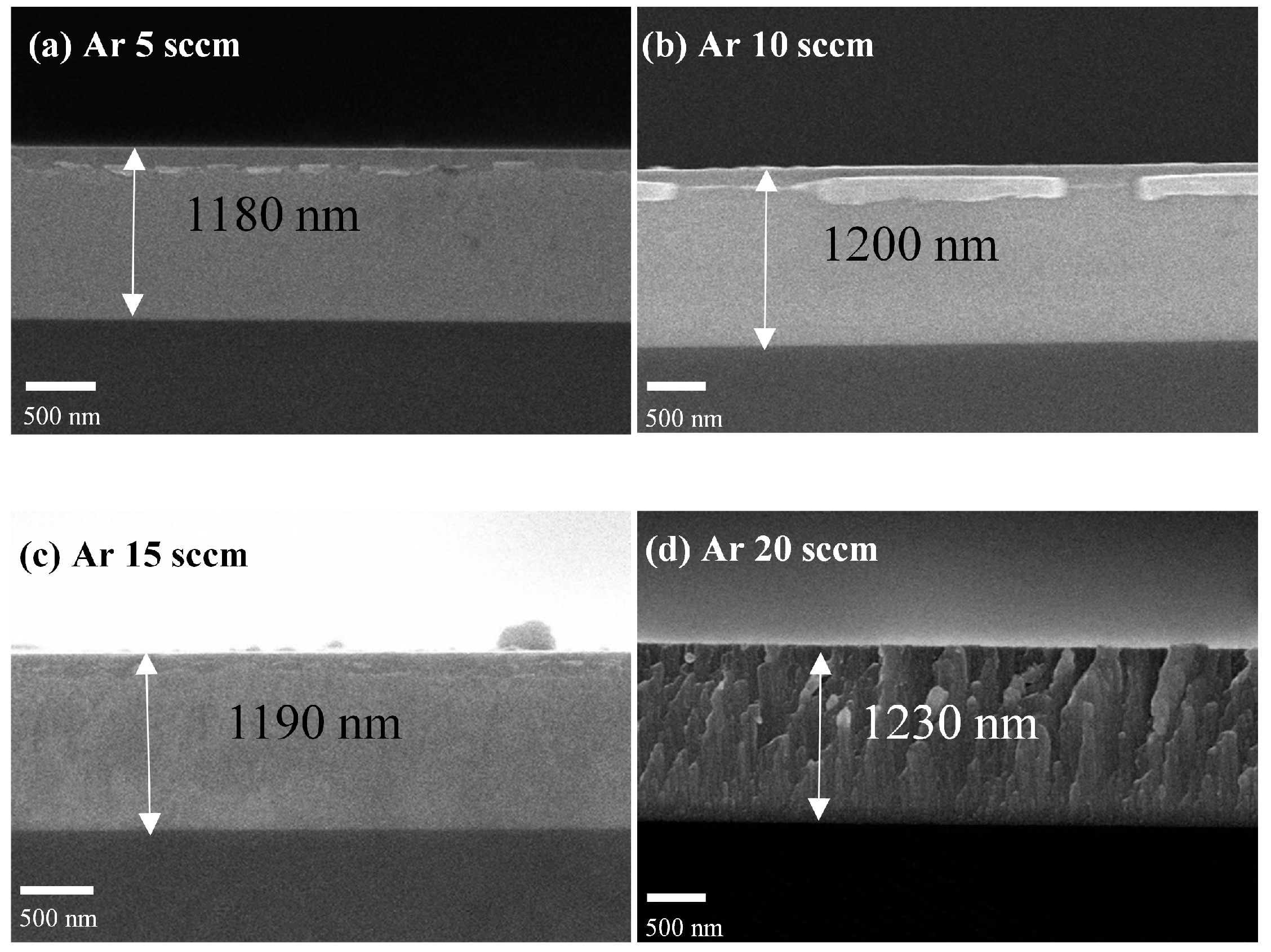
Figure 3 shows the cross-sectional images of the metallic coatings deposited under Ar flow rates ranging from 5 sccm to 20 sccm while maintaining an input power of 300 W.
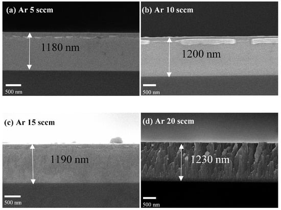
Figure 3.
Field-emission scanning electron-microscope (FE-SEM) micrographs of the cross-section of the TiZrHfNiCuCo HEA metallic coatings under different sputtering conditions: (a) Ar flow rate of 5 sccm, (b) Ar flow rate of 10 sccm, (c) Ar flow rate of 15 sccm, and (d) Ar flow rate of 20 sccm.
In the absence of additional energy inputs, such as cooling rate, temperature gradient during sputtering, or post-sputtering heat treatment, vertical growth generates a columnar structure in the metallic coatings. Figure 3d clearly shows the metallic coating exhibiting a columnar structure. At higher Ar flow rates, the interactions between the sputtered atoms and the Ar ions decrease the kinetic energy of the sputtered atoms, leading to the relative creation of porous films [42]. The less distinct columnar structures in Figure 3a to Figure 3c are likely due to the increased atomic peening effect caused by the increased mean free path resulting from reduced working pressure. Therefore, the cross-sectional images of the metallic coatings can be used to compare the densities of the metallic coatings.
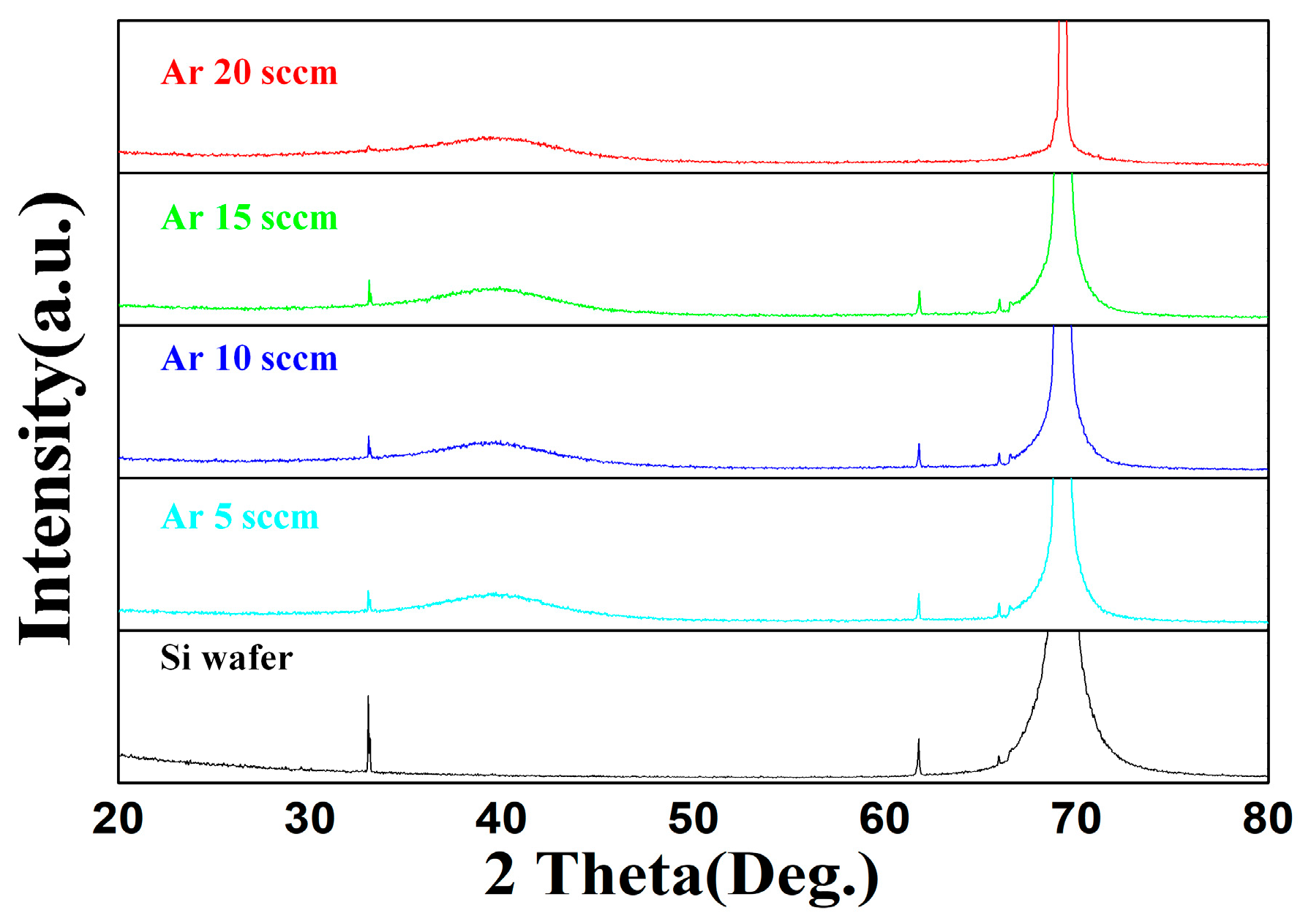
Figure 4 shows the XRD patterns of metallic coatings deposited at Ar flow rates ranging from 5 sccm to 20 sccm, with a constant input power of 300 W. Similar to the XRD results for varying input powers, a halo pattern around 39 indicates that the TiZrHfNiCuCo metallic coating exhibits a distinct tendency to adopt an amorphous structure under conditions of varying input powers and Ar flow rates.

Figure 4.
XRD diffraction patterns of a (100)-oriented p-type Si wafer substrate and the TiZrHfNiCuCo HEA metallic coatings deposited at various Ar flow rates: 20 sccm, 15 sccm, 10 sccm, and 5 sccm, with a constant input power of 300 W.
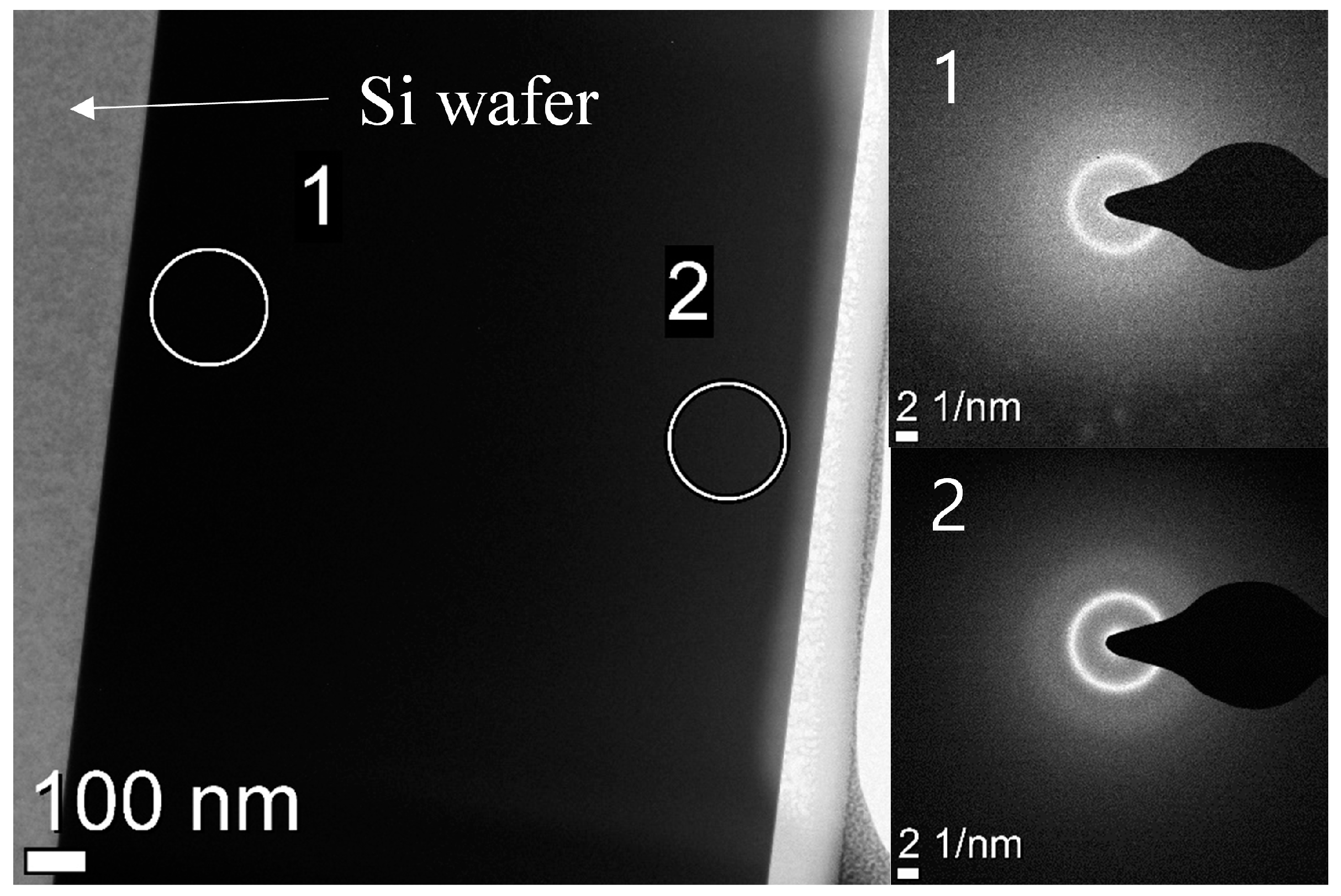
The formation of this amorphous phase in the metallic coating is generally attributed to the effects of high mixing entropy and kinetic factors in high-entropy coatings. The high mixing entropy enhances mutual solubility among the constituent elements, thereby inhibiting the development of a crystalline structure. Additionally, the rapid quenching during sputtering deposition significantly limits chemical fluctuations and suppresses crystallization [43]. For the detailed microstructure characterization, TEM analysis was performed on the metallic coating deposited at an input power of 300 W and an Ar flow rate of 5 sccm.
The TEM images and the selected area diffraction (SAED) pattern of the metallic coating are shown in Figure 5. Considering the possibility of phase transformation as the metallic coating was deposited, the analysis was conducted in two areas. In both areas, the SAED patterns showed halo ring patterns, confirming the homogeneous amorphous phase throughout the coatings. This result strongly supports the XRD analysis. Additionally, many HEA metallic films, such as AlCrMoSiTi [44], TiAlCrSiV [45], and HfNbTaTiZr [46,47], are known to have amorphous phases.

Figure 5.
Transmission electron microscope (TEM) micrographs of the cross-section and selected area electron diffraction (SAED) patterns of the TiZrHfNiCuCo HEA metallic coating at an Ar flow rate of 5 sccm.
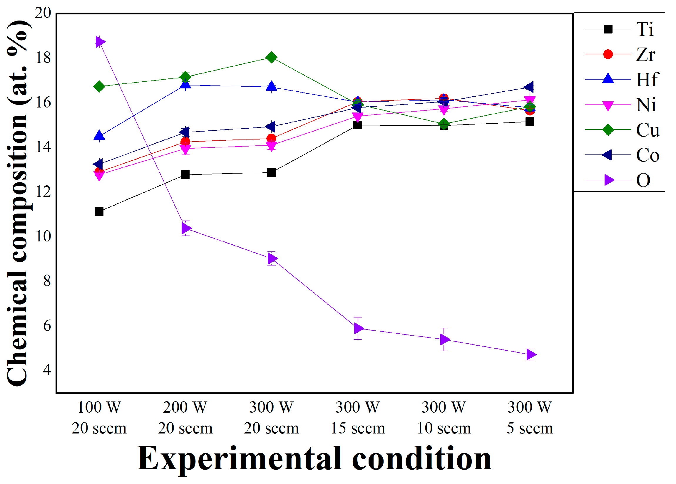
The chemical compositions (at. %) of the HEA metallic coatings were determined by EDS and are shown in Figure 6 and Table 2. For quantitative analysis, a scan area size of 2.5 μm was selected, and at least five different points were measured for statistical reliability. The composition of the specimens deposited at low input power (100 W and 200 W) and at 300 W with a gas flow rate of 20 sccm differed from the composition of the sputtering target, due to the varying degrees of scattering experienced by sputtered atoms with different masses during the sputtering process [35]. Firstly, the coating layers deposited at a low sputtering power, such as 100W or 200W, were not sufficiently thick and exhibited slight deviations from the stoichiometric ratio of the target material. In contrast, the composition of TiZrHfNiCuCo nitride coatings deposited at a low input power showed a significant difference, compared to the target composition, particularly for heavy atoms like Hf, which are scarcely detectable [25]. Nitride coatings that incorporate reactive gases showed more sensitive results to differences in input energy, compared to metallic coatings. This can be explained by the lower sputtering efficiency of reactive gases, such as N₂, compared to inert Ar ions [48]. Secondly, the metallic coating deposited at 300W with a higher gas flow rate (20 sccm) also showed slight deviations from the equiatomic ratio. Conversely, the composition of the metallic coatings closely matched the sputtering target as the gas flow rate decreased. This was because a lower working pressure and a longer mean free path allowed sputtered atoms to reach the substrate with minimal scattering caused by collisions between the sputtered atoms and the gas.
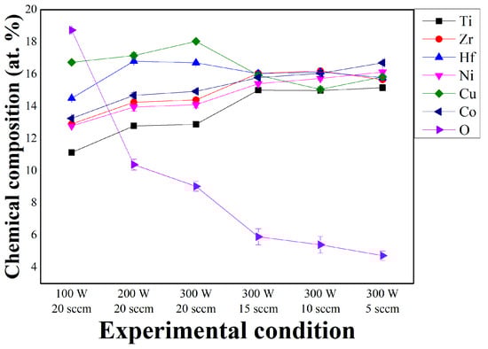
Figure 6.
Chemical composition of the TiZrHfNiCuCo coatings deposited under each condition (x-axis for illustrative purposes).
Table 2.
The chemical composition of the TiZrHfNiCuCo metallic coatings deposited under each condition.
Additionally, it was observed that the oxygen content decreased as the input power increased and the gas flow rate decreased. The oxygen content was related to the density of the metallic coating. If the metallic coating is porous, more oxygen can be detected during component analysis, due to greater oxygen intrusion into the lattice spaces [35,39]. As previously described, denser coatings were produced with a higher input power and lower gas flow rates [35,39,49]. Thus, the density of coatings and the oxygen content are interrelated. In this study, the oxygen content was expected to affect the coating quality. Therefore, to optimize the microstructure and properties of various high-entropy coatings, it is essential to conduct systematic studies on the effects of process parameters.
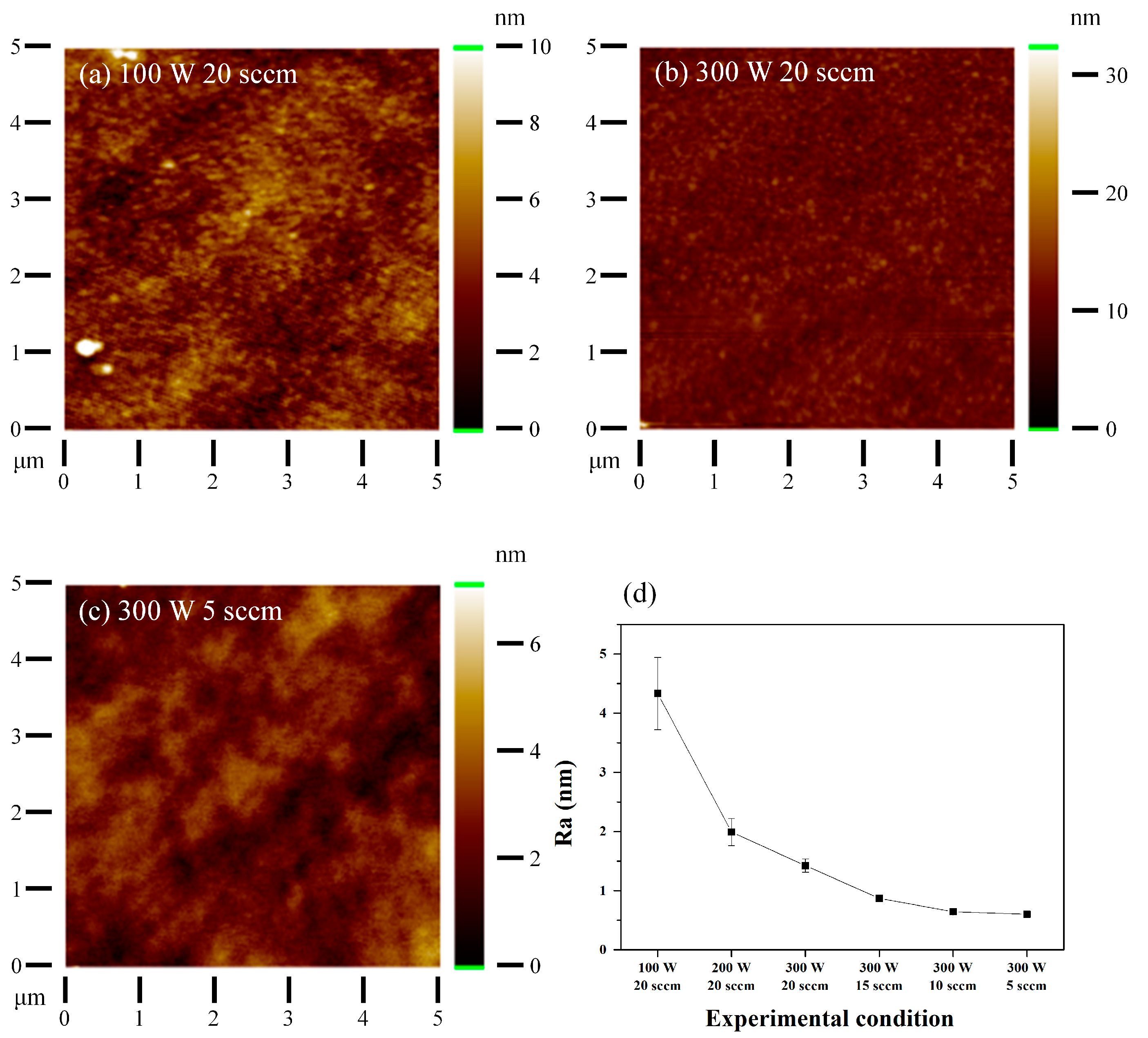
The results of surface roughness measurements using AFM under various conditions are illustrated in Figure 7 and Table 3. The surface images of the coatings under several conditions are shown in Figure 7a–c. Figure 7d demonstrates the trend of surface roughness changes under each condition, and Table 3 quantitatively presents the roughness measurements. In Table 3, extremely smooth surfaces with Ra lower than 1 nm were observed in coatings fabricated with an Ar flow rate below 20 sccm. At low Ar flow rates, the metallic coating structure was dense and smooth, with low surface roughness. As the Ar flow rate increased, the metallic coating exhibited a clear columnar structure, but the surface became highly rougher. In addition, surface roughness increased as the input power decreased. A rougher surface indicates a more porous morphology, which is closely related to coating quality. Therefore, the roughness variations according to the sputtering process variable indicate that as the momentum of the emitted sputtering atoms decreases, a rough and porous coating is formed [35,39].

Figure 7.
AFM micrographs of the TiZfHfNiCuCo metallic coatings: (a) Ar flow rate of 20 sccm with an input power of 100 W, (b) Ar flow rate of 20 sccm with an input power of 300 W, (c) Ar flow rate of 5 sccm with an input power of 300 W, and (d) roughness of the TiZrHfNiCuCo metallic coatings deposited under each condition (x-axis for illustrative purposes).
Table 3.
The roughness of the TiZrHfNiCuCo metallic coatings deposited under each condition.
The influence of the Ar flow rate and input power on the hardness and Vickers hardness of the metallic coatings is illustrated in Table 4. The TiZrHfNiCuCo metallic coating deposited at an Ar flow rate of 5 sccm and an input power of 300 W exhibited a high hardness value of 11.64 GPa, which is higher than that of its melt-spun glassy ribbon counterpart [50]. The higher hardness of the metallic coating, compared to the melt-spun glassy ribbon, is mainly attributed to the solid-solution strengthening, Hall-Petch effect, and large residual stress [35,51].
Table 4.
The hardness and Vickers hardness of TiZrHfNiCuCo metallic coatings and the TiZrHfNiCuCo melt-spun glassy ribbon.
In the case of deposited metallic films with an amorphous structure, the structure can be characterized by the assembly of nanometer-sized atomic clusters. This is distinct from the amorphous structure of metallic glasses obtained through the rapid cooling of metallic liquids, which is based on the layering of individual atoms rather than atomic clusters [52].
High power leads to the rapid deposition of particles, and the nucleation rate decreases rapidly. The smaller particles in the films have a higher surface-to-volume ratio than the larger ones, affecting the hardness profile [36]. The grain size is greatly influenced by the gas pressure in the sputter chamber, with pressure reduction leading to grain size reduction, as observed in previous studies, which explains the hardening of materials due to the Hall-Petch effect [34,53]. In this research, we can see that the hardness of the coating is closely related to the density, as evidenced by the oxygen content and surface roughness of the coating.
4. Conclusions
The TiZrHfNiCuCo metallic coatings were deposited at room temperature using a magnetron sputtering system, with variations in input power and Ar flow rate. XRD and TEM analyses revealed that the microstructure of the TiZrHfNiCuCo metallic coatings consisted of an amorphous structure. Although phase transformations due to changes in input power and Ar flow rate were not observed, significant effects were noted in terms of oxygen content, surface roughness, and mechanical properties. The oxygen content, which can be indicative of the density of the coating, was found to be lower at a higher input power and lower Ar flow rate. Specifically, at an input power of 300 W and an Ar flow rate of 5 sccm, the films exhibited a roughness of 0.603 ± 0.006 nm and a Vickers hardness of 1078 ± 21.89 HV, demonstrating enhanced density and hardness.
Author Contributions
Writing—original draft, Y.-S.K.; writing—review and editing, H.-J.P.; methodology, Y.-S.K. and H.-J.P.; investigation, Y.-S.K.; data curation, H.-J.P., S.-H.H. and Y.-S.K.; formal analysis, Y.-S.K., J.-O.S. and J.-W.S.; visualization, Y.-S.K. and H.-J.P.; conceptualization, K.-B.K.; supervision, K.-B.K.; project administration, K.-B.K. and H.-J.P. All authors have read and agreed to the published version of the manuscript.
Funding
This work was supported by the Technology Innovation Program (or Industrial Strategic Technology Development Program-Material Parts Technology Development Project) (20017502, Development of the Carbide/PCBN Cutting Tool and the Customized Cutting Solution for High Hardened Steel, by Machine Learning), funded by the Ministry of Trade, Industry, and Energy (MOTIE, Korea), and the Basic Science Research Program through the National Research Foundation of Korea (NRF), funded by the Ministry of Education (RS-2023-00250752).
Institutional Review Board Statement
Not applicable.
Informed Consent Statement
Not applicable.
Data Availability Statement
Data are contained within the article.
Conflicts of Interest
The authors declare that they have no known competing financial interests or personal relationships that could have appeared to influence the work reported in this paper.
References
- Cantor, B.; Chang, I.T.H.; Knight, P.; Vincent, A.J.B. Microstructural development in equiatomic multicomponent alloys. Mater. Sci. Eng. A 2004, 375, 213–218. [Google Scholar] [CrossRef]
- Yeh, J.W. Recent progress in high entropy alloys. Ann. Chim. Sci. Mat 2006, 31, 633–648. [Google Scholar] [CrossRef]
- Zhang, Y.; Zhou, Y.J.; Lin, J.P.; Chen, G.L.; Liaw, P.K. Solid-solution phase formation rules for multi-component alloys. Adv. Eng. Mater. 2008, 10, 534–538. [Google Scholar] [CrossRef]
- George, E.P.; Raabe, D.; Ritchie, R.O. High-entropy alloys. Nat. Rev. Mater. 2019, 4, 515–534. [Google Scholar] [CrossRef]
- Tsai, K.Y.; Tsai, M.H.; Yeh, J.W. Sluggish diffusion in Co-Cr-Fe-Mn-Ni high-entropy alloys. Acta Mater. 2013, 61, 4887–4897. [Google Scholar] [CrossRef]
- Miracle, D.B.; Senkov, O.N. A critical review of high entropy alloys and related concepts. Acta Mater. 2017, 122, 448–511. [Google Scholar] [CrossRef]
- Kim, H.; Nam, S.; Roh, A.; Son, M.; Ham, M.-H.; Kim, J.-H.; Choi, H. Mechanical and electrical properties of NbMoTaW refractory high-entropy alloy thin films. Int. J. Refract. Met. Hard Mater. 2019, 80, 286–291. [Google Scholar] [CrossRef]
- Zhu, Z.-X.; Liu, X.-B.; Liu, Y.-F.; Zhang, S.-Y.; Meng, Y.; Zhou, H.-B.; Zhang, S.-H. Effects of Cu/Si on the microstructure and tribological properties of FeCoCrNi high entropy alloy coating by laser cladding. Wear 2023, 512, 204533. [Google Scholar] [CrossRef]
- Patel, P.; Nair, R.B.; Supekar, R.; McDonald, A.; Chromik, R.R.; Moreau, C.; Stoyanov, P. Enhanced wear resistance of AlCoCrFeMo high entropy coatings (HECs) through various thermal spray techniques. Surf. Coatings Technol. 2024, 477, 130311. [Google Scholar] [CrossRef]
- Zou, Y.; Ma, H.; Spolenak, R. Ultrastrong ductile and stable high-entropy alloys at small scales. Nat. Commun. 2015, 6, 1–8. [Google Scholar] [CrossRef]
- Zhang, F.; Zhao, R.; Ma, H.; Jin, H.; Wang, L.; He, S.; Yin, F. Microstructure, mechanical properties and tribological behavior of (TiZrHfNbTa) Nx high entropy films deposited by magnetron sputtering. Ceram. Int. 2024, 50, 13070–13081. [Google Scholar] [CrossRef]
- Gludovatz, B.; Hohenwarter, A.; Catoor, D.; Chang, E.H.; George, E.P.; Ritchie, R.O. A fracture-resistant high-entropy alloy for cryogenic applications. Science 2014, 345, 1153–1158. [Google Scholar] [CrossRef] [PubMed]
- Obeydavi, A.; Shafyei, A.; Lee, J.-W. Effect of sputtering power and substrate bias on microstructure, mechanical properties and corrosion behavior of CoCrFeMnNi high entropy alloy thin films deposited by magnetron sputtering method. Intermetallics 2024, 172, 108369. [Google Scholar] [CrossRef]
- El-Atwani, O.; Li, N.; Li, M.; Devaraj, A.; Baldwin, J.K.S.; Schneider, M.M.; Sobieraj, D.; Wróbel, J.S.; Nguyen-Manh, D.; Maloy, S.A. Outstanding radiation resistance of tungsten-based high-entropy alloys. Sci. Adv. 2019, 5, eaav2002. [Google Scholar] [CrossRef]
- Cheng, Z.; Sun, J.; Gao, X.; Wang, Y.; Cui, J.; Wang, T.; Chang, H. Irradiation effects in high-entropy alloys and their applications. J. Alloys Compd. 2023, 930, 166768. [Google Scholar] [CrossRef]
- Yan, X.H.; Li, J.S.; Zhang, W.R.; Zhang, Y. A brief review of high-entropy films. Mater. Chem. Phys. 2018, 210, 12–19. [Google Scholar] [CrossRef]
- Jin, H.; Seok, Y.; Hoon, Y.; Hwan, S.; Sik, K.; Koon, Y.; Buem, K. Design of nano-scale multilayered nitride hard coatings deposited by arc ion plating process: Microstructural and mechanical characterization. J. Mater. Res. Technol. 2021, 15, 572–581. [Google Scholar] [CrossRef]
- Pierson, H.O. Handbook of Refractory Carbides & Nitrides: Properties, Characteristics, Processing and Applications; Noyes Publications: Trenton, NJ, USA, 1996. [Google Scholar]
- Li, W.; Liu, P.; Liaw, P.K. Microstructures and properties of high-entropy alloy films and coatings: A review. Mater. Res. Lett. 2018, 6, 199–229. [Google Scholar] [CrossRef]
- Park, H.J.; Kim, Y.S.; Mun, S.C.; Hong, S.H.; Wang, W.-M.; Kim, K.B. Designing of Fe-containing (Ti33Zr33Hf33)-(Ni50Cu50) high entropy alloys developed by equiatomic substitution: Phase evolution and mechanical properties. J. Mater. Res. Technol. 2020, 9, 7732–7739. [Google Scholar] [CrossRef]
- Braeckman, B.R.; Depla, D. Structure formation and properties of sputter deposited Nbx-CoCrCuFeNi high entropy alloy thin films. J. Alloys Compd. 2015, 646, 810–815. [Google Scholar] [CrossRef]
- Cui, K.; Zhang, Y. High-entropy alloy films. Coatings 2023, 13, 635. [Google Scholar] [CrossRef]
- Zhao, K.; Hao, X.; Ma, D.; Huang, B.; Zhao, X.; Ma, J.; Wang, C. The key role in the structure and properties of a novel CrNiTiMo high-entropy alloys films prepared by magnetron sputtering: Bias voltage. J. Mater. Res. Technol. 2024. [Google Scholar] [CrossRef]
- Liao, W.; Lan, S.; Gao, L.; Zhang, H.; Xu, S.; Song, J.; Wang, X.; Lu, Y. Nanocrystalline high-entropy alloy (CoCrFeNiAl0.3) thin-film coating by magnetron sputtering. Thin Solid Films 2017, 638, 383–388. [Google Scholar] [CrossRef]
- Seok, Y.; Jin, H.; Chul, S.; Jumaev, E.; Hwan, S.; Song, G.; Tae, J.; Koon, Y.; Sik, K.; Il, S.; et al. Investigation of structure and mechanical properties of TiZrHfNiCuCo high entropy alloy thin fi lms synthesized by magnetron sputtering. J. Alloys Compd. 2019, 797, 834–841. [Google Scholar] [CrossRef]
- Kim, Y.-S.; Park, H.-J.; Kim, Y.-S.; Hong, S.-H.; Kim, K.-B. Influence of the Gas Flow Rate on the Crack Formation of AlCoCrNi High-Entropy Metallic Film Fabricated Using Magnetron Sputtering. Coatings 2024, 14, 144. [Google Scholar] [CrossRef]
- Kim, Y.S.; Park, H.J.; Lim, K.S.; Hong, S.H.; Kim, K.B. Structural and mechanical properties of AlCoCrNi high entropy nitride films: Influence of process pressure. Coatings 2019, 10, 10. [Google Scholar] [CrossRef]
- Al-Mansoori, M.; Al-Shaibani, S.; Al-Jaeedi, A.; Lee, J.; Choi, D.; Hasoon, F.S. Effects of gas flow rate on the structure and elemental composition of tin oxide thin films deposited by RF sputtering. AIP Adv. 2017, 7, 125105. [Google Scholar] [CrossRef]
- Vijaya, G.; Singh, M.M.; Krupashankara, M.S.; Kulkarni, R.S. Effect of argon gas flow rate on the optical and mechanical properties of sputtered tungsten thin film coatings. In IOP Conference Series: Materials Science and Engineering; IOP Publishing: Bristol, UK, 2016; Volume 149, p. 12075. [Google Scholar] [CrossRef]
- An, Z.; Ding, H.; Meng, Q.; Rong, Y. Kinetic equation of the effect of thickness on grain growth in nanocrystalline films. Scr. Mater. 2009, 61, 1012–1015. [Google Scholar] [CrossRef]
- Park, H.J.; Na, Y.S.; Hong, S.H.; Kim, J.T.; Kim, Y.S.; Lim, K.R.; Park, J.M.; Kim, K.B. Phase evolution, microstructure and mechanical properties of equi-atomic substituted TiZrHfNiCu and TiZrHfNiCuM (M = Co, Nb) high-entropy alloys. Met. Mater. Int. 2016, 22, 551–556. [Google Scholar] [CrossRef]
- Oliver, W.C.; Pharr, G.M. An improved technique for determining hardness and elastic modulus using load and displacement sensing indentation experiments. J. Mater. Res. 1992, 7, 1564–1583. [Google Scholar] [CrossRef]
- Qi, Z.; Wu, Z.; Zhang, D.; Wei, B.; Wang, J.; Wang, Z. Effect of sputtering power on the chemical composition, microstructure and mechanical properties of CrN x hard coatings deposited by reactive magnetron sputtering. Vaccum 2017, 145, 136–143. [Google Scholar] [CrossRef]
- Srinivas, K.; Raja, M.M.; Rao, D.V.S.; Kamat, S.V. Effect of sputtering pressure and power on composition, surface roughness, microstructure and magnetic properties of as-deposited Co2FeSi thin films. Thin Solid Films 2014, 558, 349–355. [Google Scholar] [CrossRef]
- Tsai, D.-C.; Chang, Z.-C.; Kuo, B.-H.; Chen, B.-C.; Chen, E.-C.; Shieu, F.-S. Wide variation in the structure and physical properties of reactively sputtered (TiZrHf) N coatings under different working pressures. J. Alloys Compd. 2018, 750, 350–359. [Google Scholar] [CrossRef]
- Venkatesh, R.; Banapurmath, N.R.; Modagi, S.; Hallod, S.A.; Shetter, A.S. Analysis of the effect of sputter power on the morphological and mechanical characteristics of titanium thin films deposited on high-speed steel (HSS). Mater. Today Proc. 2020, 27, 59–61. [Google Scholar] [CrossRef]
- Mahan, J.E. Physical Vapor Deposition of Thin Films; Wiley-Interscience: New York, NY, USA, 2000. [Google Scholar]
- Campbell, S.A. The Science and Engineering of Microelectronic Fabrication; Oxford Press: New York, NY, USA, 2001. [Google Scholar]
- Tsai, D.-C.; Chang, Z.-C.; Kuo, B.-H.; Tsao, C.-T.; Chen, E.-C.; Shieu, F.-S. Influence of discharge power on the structural, electro-optical, and mechanical properties of (TiZrHf) N coatings. J. Alloys Compd. 2015, 622, 446–457. [Google Scholar] [CrossRef]
- Chan, K.-Y.; Teo, B.-S. Sputtering power and deposition pressure effects on the electrical and structural properties of copper thin films. J. Mater. Sci. 2005, 40, 5971–5981. [Google Scholar] [CrossRef]
- El-Kadry, N.; Ashour, A.; Mahmoud, S.A. Structural dependence of dc electrical properties of physically deposited CdTe thin films. Thin Solid Films 1995, 269, 112–116. [Google Scholar] [CrossRef]
- Mohri, M.; Wang, D.; Ivanisenko, J.; Gleiter, H.; Hahn, H. Investigation of the deposition conditions on the microstructure of TiZrCuPd nano-glass thin films. Mater. Charact. 2017, 131, 140–147. [Google Scholar] [CrossRef]
- Ren, B.; Shen, Z.; Liu, Z. Structure and mechanical properties of multi-element (AlCrMnMoNiZr) Nx coatings by reactive magnetron sputtering. J. Alloys Compd. 2013, 560, 171–176. [Google Scholar] [CrossRef]
- Chang, H.-W.; Huang, P.-K.; Davison, A.; Yeh, J.-W.; Tsau, C.-H.; Yang, C.-C. Nitride films deposited from an equimolar Al–Cr–Mo–Si–Ti alloy target by reactive direct current magnetron sputtering. Thin Solid Films 2008, 516, 6402–6408. [Google Scholar] [CrossRef]
- Lin, C.H.; Duh, J.G.; Yeh, J.W. Multi-component nitride coatings derived from Ti–Al–Cr–Si–V target in RF magnetron sputter. Surf. Coatings Technol. 2007, 201, 6304–6308. [Google Scholar] [CrossRef]
- Hruška, P.; Lukáč, F.; Cichoň, S.; Vondráček, M.; Čížek, J.; Fekete, L.; Lančok, J.; Veselý, J.; Minárik, P.; Cieslar, M. Oxidation of amorphous HfNbTaTiZr high entropy alloy thin films prepared by DC magnetron sputtering. J. Alloys Compd. 2021, 869, 157978. [Google Scholar] [CrossRef]
- Wang, N.; Cao, Q.; Wang, X.; Ding, S.; Zhang, D.; Jiang, J.-Z. Ultra-strong and ductile amorphous-crystalline Ti-Zr-Hf-Nb-Ta/Co-Ni-V nanolaminate thin films. J. Alloys Compd. 2024, 973, 172874. [Google Scholar] [CrossRef]
- Mason, R.S.; Pichilingi, M. Sputtering in a glow discharge ion source-pressure dependence: Theory and experiment. J. Phys. D. Appl. Phys. 1994, 27, 2363. [Google Scholar] [CrossRef]
- French, B.L.; Bilello, J.C. In situ observations of the real-time stress-evolution and delamination of thin Ta films on Si (100). Thin Solid Films 2004, 446, 91–98. [Google Scholar] [CrossRef]
- Hong, S.H.; Park, H.J.; Kang, G.C.; Kim, Y.S.; Song, G.; Kim, K.B. Nanocrystalline single-phase high-entropy alloy synthesized by using intermetallic compound type (TiZrHf)-(NiCuCo) high-entropy metallic glass precursor. Scr. Mater. 2022, 209, 114391. [Google Scholar] [CrossRef]
- He, W.; Bhole, S.D.; Chen, D. Modeling the dependence of strength on grain sizes in nanocrystalline materials. Sci. Technol. Adv. Mater. 2008, 9, 15003. [Google Scholar] [CrossRef]
- Zhang, J.Y.; Ding, Z.Y.; Li, F.C.; Yang, Y. Controlled synthesis of nanostructured glassy and crystalline high entropy alloy films. Nanotechnology 2019, 31, 45601. [Google Scholar] [CrossRef]
- Peng, B.; Zhang, W.L.; Xie, Q.Y.; Zhang, W.X.; Jiang, H.C. Effect of sputtering pressure on microstructure and magnetic properties of amorphous FeCoSiB films. J. Non. Cryst. Solids 2013, 365, 59–62. [Google Scholar] [CrossRef]
Disclaimer/Publisher’s Note: The statements, opinions and data contained in all publications are solely those of the individual author(s) and contributor(s) and not of MDPI and/or the editor(s). MDPI and/or the editor(s) disclaim responsibility for any injury to people or property resulting from any ideas, methods, instructions or products referred to in the content. |
© 2024 by the authors. Licensee MDPI, Basel, Switzerland. This article is an open access article distributed under the terms and conditions of the Creative Commons Attribution (CC BY) license (https://creativecommons.org/licenses/by/4.0/).