Article

The Change of Sealing Property in the Aging Process of NBR Sealing Equipment Based on Finite Element Analysis

1
College of Nuclear Science and Technology, Naval University of Engineering, Wuhan 430033, China
2
College of Weapon Engineering, Naval University of Engineering, Wuhan 430033, China
*
Authors to whom correspondence should be addressed.
Coatings 2024, 14(9), 1178; https://doi.org/10.3390/coatings14091178
Submission received: 1 August 2024 / Revised: 6 September 2024 / Accepted: 10 September 2024 / Published: 12 September 2024

Abstract

:
Sealing rings are the core components of flange sealing structures and play a crucial role in the storage and operation of gas generators. The aging and deformation of seals affect the safe operation of the device. This paper aims to investigate the effect of rubber aging on the sealing performance of the components, which is realized by nonlinear finite element analysis. Firstly, an accelerated degradation test method was used to obtain the compression permanent deformation and stress–strain curve of rubber during the aging process. A two-dimensional finite element model of the sealing structure was constructed and the Yeoh model was utilized to describe the mechanical response of rubber. During the simulation, the contact area was modified based on the compression permanent deformation, and the Yeoh model was updated based on the stress–strain curve changes obtained by the test. The impact of key parameters such as material property changes, rubber physical section deformation, and fluid pressure on sealing performance during the seal ring aging process was systematically studied. The numerical results indicate that due to the aging deformation of rubber seals, there is a significant decrease in contact stress and contact width, as well as a shift in maximum equivalent stress area. Taking into account these findings, this study proposes a new design concept for sealing structures. This provides a relatively simple research method for studying flange sealing structure performance.

Graphical Abstract

1. Introduction

Gas generators are primarily used for the launch of rockets and surface-to-surface weapons. The main components include the combustion chamber, igniter cartridge, propellant column, nozzle, and rubber sealing ring. Currently, there are two methods for launching rockets and surface-to-surface weapons: hot launch and cold launch. Hot launch refers to the use of the rocket’s own power source for propulsion. Cold launch involves using a gas generator to produce high-temperature and high-pressure gas to propel the rocket into the air before ignition. Cold launch allows for ignition at high altitudes without causing erosion to ground facilities.
Rocket launches are often delayed due to a series of pre-launch conditions that need to be met. For surface-to-surface weapons, gas generators are rarely used, with most being stored for many years before being decommissioned. After prolonged storage, degradation in the performance of polymer materials can lead to decreased sealing effectiveness, potentially resulting in gas leaks during launches. This could prevent rockets from obtaining sufficient power for successful launches and may also cause damage to the surrounding environment through gas leakage. The sealing ring is a key component of the flange sealing structure of the gas generator. It has the advantages of a simple structure and good self-sealing effect, and is suitable for various sealing environments such as gas tightness and water tightness [1,2,3,4]. As a polymer material, rubber seals can undergo gradual and irreversible changes in their macromolecular network as a result of environmental influences [5]. This change is driven by two mechanisms operating at the microscopic level: crosslinking and chain scission, which in turn impact their macroscopic mechanical properties [6,7]. When the sealing ring is compressed, a seal is formed in the contact area between the sealing ring and the flange plate. However, aging can lead to a gradual decrease in the contact pressure of the sealing ring. When this contact pressure falls below a certain value, the structure loses its ability to maintain a proper seal [8]. The modern design requirements for gas generators emphasize high reliability and a long service life, which has led to a shift from rubber materials to high-performance materials. This transition has also increased the need for evaluating changes in sealing performance throughout the life cycle.
Li et al. [9] conducted a study on the thermal oxidative aging and compressive stress–thermal oxidative aging of rubber under various temperatures and compressive stresses. The findings indicated that both temperature and compressive stress led to a reduction in the mechanical properties and sealing resilience of the rubber. Yang et al. [10] conducted a study on the impact of key structural parameters on the sealing performance of a belt-framed seal ring, and identified the optimal parameters for achieving effective sealing. The rationality of the sealing structure was confirmed through gate sealing performance testing. Xie et al. [11] demonstrated the reduction in contact pressure during aging through aging tests, numerical simulations, and atomic force microscopy (AFM) tests. Jiang et al. investigated the issue of seal failure in a water quality monitoring system under low-temperature conditions. They utilized a two-dimensional axisymmetric model to study the variation in sealing performance of rubber seals during standard temperature installation and low-temperature installation. The numerical results indicate that, with the influence of medium pressure, the maximum contact stress of the rubber seal increased from 2.6285 MPa at 20 °C to 2.6657 MPa at 0 °C [12]. Liu et al. studied the aging laws of storage performance and stress aging of rubber seals. When the compression permanent deformation of the seal is 50% at a compression rate of 12.5%, the predicted lifespan of the seal is 12.6 years [13]. Luo et al. investigated the influence of hydrothermal aging on the friction performance of cylinder seals through hydrothermal aging tests, friction tests, tensile and compression tests, morphology analysis, infrared spectroscopy analysis, and multiscale simulations. The study revealed that as the aging temperature increased from 40 °C to 80 °C, the dynamic friction force of the cylinder seal increased by more than 15%. Furthermore, it was observed that the friction force increased with an increase in initial mechanical stress [14].
The above research has greatly contributed to the exploration of the performance of rubber seals under different conditions. However, most of these studies directly measure the sealing performance of the seals through various experimental methods. Although they characterize the performance degradation caused by seal aging at multiple scales, they do not analyze the reasons for this degradation. There is little research on the impact of seal aging deformation, especially on the influence of deformation caused by aging on seals, which is rarely reported in the existing literature. When designing the sealing structure, researchers often optimize the design for the initial state structure, but in fact, due to changes in the physical cross-section of the sealing ring, the parameters of the sealing structure are not optimal for the aging and deformed sealing ring. This study aims to analyze the series of impacts brought by rubber aging deformation, in order to provide new research ideas and directions for analyzing seal failure.
Therefore, this article carried out accelerated degradation tests to quickly obtain equivalent aging samples, and used finite element analysis methods to quickly evaluate the contact pressure degradation caused by the aging deformation of the sealing ring. Considering the aging deformation of the sealing ring, adjusting and optimizing the sealing structure parameters can maintain good sealing performance for the aging and deformed sealing ring. The simplified structure of a gas generator is shown in Figure 1.

2. Materials and Methods

2.1. Materials

Nitrile rubber is from Qingdao Yike Rubber & Plastic Co., Ltd. (Qingdao, China), which did not disclose the rubber formula for commercial reasons. The sample we obtained was a 10 mm diameter seal ring, which was cut into small 10 mm high pieces for aging testing in an oven (show in Figure 2).

2.2. Aging Methods

The thermal aging accelerated tests were conducted in air-circulating ovens to investigate the compression permanent deformation and stress–strain performance changes of nitrile rubber under compression. The samples were placed in between two stainless steel plates bolted together to maintain a constant aging compressive strain of 30%.
For compression set testing, the sample continues to age after being measured. In compression set testing, eight samples were aged at 80 °C, 90 °C, 100 °C, 110 °C, 120 °C, and 130 °C, which was removed from the air circulation furnace to measure the performance at specific time points: 6 h, 14 h, 30 h, 54 h, 93 h, 140 h, 188 h, 263 h for 80 °C and 90 °C; 4 h, 10 h, 21 h, 34 h, 55 h, 70 h, 93 h, 114 h for 120 °C and 130 °C. Every sample was observed for cracks during each sampling. If the sample remains intact, record its performance changes and continue testing until all samples are measured within the specified time interval.
For stress-strain testing, in order to eliminate the error caused by rubber damage during the testing process, the samples are discarded after each test. Rubber was sampled and tested for aging at 80 °C for 19 h, 38 h, 76 h, 114 h, 152 h, 189 h and 228 h. Three samples were tested at each sampling point.

2.3. Compressed Permanent Deformation Tests

Thickness gauge was used to record the height of NBR after aging, and the compression permanent deformation was calculated according to the height before and after aging. Referring to GB T 7759 [15], the compression set can be expressed as
ε = h 0 h t h 0 h s
where h 0 is the initial height before aging; h t is the recovered height after aging; h s is the height of the limiter.

2.4. Uniaxial Compression Tests

The temperature and aging time-dependent mechanical responses of the unaged and aged samples under different conditions were investigated by conducting uniaxial compression tests. Place the aged cylindrical specimen on the fixture and set the compression rate to 1 mm/min. Start the universal testing machine until the strain of the rubber specimen reaches 45%. Upon completion of loading, unload the load and allow the specimen to fully rebound. To eliminate the Mullins effect of the specimens, each specimen needs to undergo three pre-compression tests, and record data for force and displacement during the fourth test [16].
After the rubber specimens undergo accelerated degradation tests, their heights exhibit varying changes. Therefore, prior to formal testing, it is necessary to use a rubber thickness gauge to obtain the actual dimensions of the deformed specimens and then apply a formula to convert the measured force–displacement data into corresponding nominal stress–strain values.
σ = F A = F π d 2 2 = 4 F π d 2
ε = l l

3. Test Results and Analysis

In the process of thermal oxygen aging, nitrile rubber will react with oxygen in the air to generate polar functional groups such as C=O and -OH, accompanied by crosslinking and breaking of molecular chains. When nitrile rubber is subjected to compressive loading, the breakage and recombination of molecular chains will cause the compressive set of the polymer and the change of stress–strain response. As a result, the sealing performance of nitrile rubber is reduced and the safe use of equipment is affected.

3.1. Analysis of Compression Set

Figure 3a shows the relationship between the compression set and aging time at different temperatures. According to the characteristics of the compression set, it can be fitted through empirical formulas [8], as shown in Figure 3b:
1 ε = B e K t α
Among these parameters, ε represents the compression set, B is the experimental constant, K denotes the aging reaction rate, α signifies the time constant, and t stands for the aging time.
The accelerated aging test needs to ensure that the failure mechanism of rubber is consistent; therefore, it is necessary to further determine the rationality of the test temperature based on experimental data. Considering the occurrence of non-Arrhenius behavior in material aging, which indicates that the activation energy of the material varies at different temperature ranges, we calculated the activation energy with the compression set as the indicator for different temperature ranges. The activation energy can be obtained by fitting the Arrhenius equation [8,9]:
K = A e E / R T
Among these parameters, A is the frequency factor ( d 1 ), E is the apparent activation energy ( J · m o l 1 ), R is the gas constant ( J · K 1 · m o l 1 ), T is the thermodynamic temperature.
The activation energies at different temperatures are shown in Figure 4, the results show that when the temperature exceeds 110 °C, the rubber exhibits significant non-Arrhenius behavior, and the activation energy of the material reaction undergoes a significant change. This indicates that the failure mechanism changes when the aging temperature exceeds 110 °C, compared to room temperature. Therefore, relevant parameters were calculated using experimental data at 80–110 °C, and we used the least squares method to find optimal parameters and calculate their equivalent relationship.

3.2. Analysis of Stress–Strain

The relationship between the reaction rate and temperature was determined by analyzing the activation energy. Through the analysis of compression permanent deformation in Section 3.2, we obtained the equivalent aging time at 80 °C to room temperature (25 °C), as shown in Table 1.
Uniaxial compression tests were conducted on rubber specimens with different aging times, and their stress–strain curves were obtained, as shown in Figure 5. The test results indicate that in the early stage of sample aging, the properties of the sample change rapidly. With an increase in time, the changes in material properties gradually tend to flatten. The overall trend shows that the material gradually becomes harder with an increase in aging time.
Here, a constitutive model is used to study the changes in stress–strain curves. The rubber material is a typical hyperelastic material, and its constitutive relationship is very complex. It is essential to choose a suitable material constitutive model and obtain accurate material constitutive model parameters for accurately simulating material deformation [17]. The Yeoh model has been widely used to describe the hyperelastic response of rubbers [18,19,20,21,22], and the third-order Yeoh model is the most suitable for HNBR [19]. Therefore, the Yeoh model is used as the constitutive model for Nitrile rubber. The Yeoh model is expressed as
W = i = 1 i = 3 [ C i I 1 3 i + 1 D i J 1 2 ]
where Ci and Di are the parameters of the material model, which can be determined by uniaxial tensile tests; I1 is the first fundamental invariant of the Cauchy–Green deformation tensor, I 1 = λ 1 2 + λ 2 2 + λ 3 2 ; J is the volume ratio of material thermal expansion. Rubber is generally considered an incompressible material, i.e., λ 2 2 = λ 3 2 = λ 1 , I 1 = λ 1 2 + 2 λ 1 and J = 1. Thus
W = i = 1 i = 3 C i I 1 3 i
The changes in Yeoh model parameters with aging time obtained through fitting are shown in Table 2.
Through fitting, it was found that there is a power exponential relationship between Ci and time [20], that is
C i = a t b + c
The specific expression is shown in Equation (9), and the fitting effect is shown in Figure 6
C 1 = 7.855 × 10 6 × t + 1.108
C 2 = 5.979 × 10 4 × t 0.3689 + 0.02033
C 3 = 2.646 × 10 2 × t 0.2880 + 0.4146

3.3. Finite Element Analysis

3.3.1. Analytical Model of Sealing Structure

The gas generator’s sealing structure is an axisymmetric solid, and the model is simplified to a planar axisymmetric model, as show in Figure 7. Due to the much lower stiffness of the rubber material compared to that of the upper and lower flanges, the upper and lower flanges are simplified to analytical rigid bodies in order to accelerate calculation and improve model convergence. The contact between the sealing ring and the upper and lower flanges is defined as frictional contact with a friction coefficient of 0.12, while the sealing ring is selected as CPE4RH grid element type. Based on the degree of aging of the sealing ring, the geometric boundary of the sealing ring is determined. The width of the sealing groove is 12 mm, and the height is 6 mm, with both the upper and lower fillet radii set at 0.6 mm. The material of the sealing ring is a highly elastic material, and based on the stress–strain fitting effect, the Yeoh constitutive model is selected with specific parameters as shown in Table 2. During simulation, the flange is completely fixed when the displacement is applied, and the upper and lower flanges are completely fixed when the air pressure is applied. The penalty function is used to increase the convergence. The gap is automatically controlled by the software. The contact mode is surface–surface contact, and the contact stiffness value is set by the software and automatically adjusted gradually to make the model become stable.
The analysis is conducted in two steps. The first step involves fixing the lower flange and moving the upper flange downwards to achieve pre-tightening sealing of the sealing ring. In the second step, fluid permeation pressure load is applied on the inner side of the sealing ring to simulate changes in its state during operation, and ABAQUS software (version 2022) is used for calculation.
To ensure high accuracy in calculations, grid independence is employed to examine the impact of grid on calculation results after each change in settings and model parameters until the results tend to stabilize. Table 3 presents the grid independence verification of the unaged sealing ring at a pressure of 1 MPa. It shows that when the number of grids exceeds 4028, the calculation results tend to stabilize. When there are 16,692 grids, errors between maximum contact pressure and maximum equivalent stress are 0.07% and 0.06%, meeting precision requirements.
The contact pressure of the sealing ring gradually changes with material aging. This is due to alterations in the physical cross-section, which lead to variations in compression rate and sealing state under the same sealing gap, resulting in changes in contact pressure.
Experiments have shown that the physical cross-section of the sealing ring undergoes changes, with its upper and lower surfaces gradually flattening while the left and right cross-sections exhibit a certain expansion trend [23], which is approximately elliptical. Therefore, for approximation purposes, the physical cross-section of the sealing ring is simplified to an elliptical shape. Due to the approximate incompressibility of rubber materials, their cross-sectional area remains approximately unchanged. It is assumed that the deformation law of the short axis of the ellipse (perpendicular to the compression direction) conforms to the degradation trajectory of compression permanent deformation. According to the compression permanent deformation of the sealing ring, the change in its physical cross-section is shown in Figure 8. By keeping the sealing gap unchanged, different degrees of aging are introduced into finite element analysis models along with their corresponding material properties in order to analyze how aging deformation affects rubber sealing rings’ sealing performance.
Adopting the maximum contact pressure stress criterion: When the maximum contact pressure stress σ m a x between the rubber seal ring and the flange in working conditions is less than the working internal pressure P, it will cause gas leakage and seal failure. Therefore, the maximum contact pressure stress is the primary condition for failure criteria and judgment, ensuring that the seal meets [24]
σ m a x P
Figure 9a illustrates the distribution of contact pressure along the contact length of the equivalent aged 3a sealing ring under different air pressures. The solid line represents the distribution considering cross-sectional deformation, while the dotted line represents the distribution without considering deformation. For the equivalent aging 3a sealing ring, under a gas pressure of 1 MPa, the calculated maximum contact pressure caused by cross-sectional changes differs by 43.6%.
There is also a significant difference in contact length. Figure 9b presents the distribution of contact pressure along the contact length when only considering changes in material properties. The solid line represents the distribution of equivalent aged 3a sealing rings, and the dotted line represents the distribution of non-aged sealing rings. If only considering changes in material properties, due to the gradual hardening trend of rubber materials over time, it is observed that there is actually a significant increase in trend for maximum contact pressure with material aging, which contradicts actual observations.
Based on comprehensive analysis, it can be concluded that considering the influence of changes in the sealing ring cross-section on analyzing changes in the sealing performance is significant.

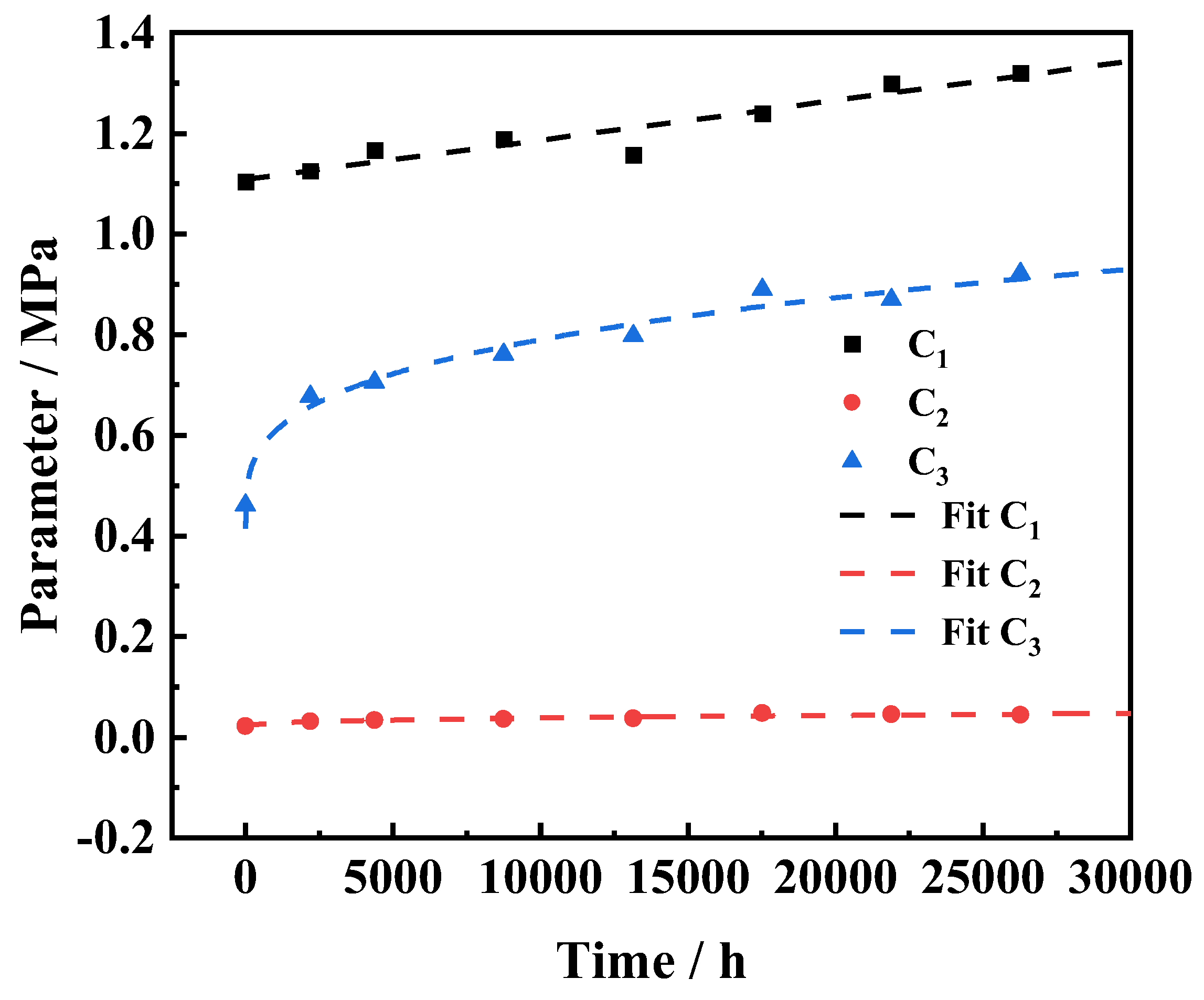
3.3.2. Mechanical Properties of Sealing Rings

Figure 10 and Figure 11 illustrate the stress distribution of the non-aged sealing ring and the equivalent aged 3a sealing ring. A comprehensive analysis leads to the conclusion that the deformation of both the non-aged sealing ring and the aged 3a sealing ring are similar. At low gas pressure, the most significant deformation occurs near the upper and lower surfaces. As gas pressure gradually increases, the deformation of the sealing ring also changes gradually. When gas pressure reaches 7 MPa, the area with the most significant deformation shifts to near the upper and lower rounded corners, resulting in a certain degree of extrusion along the sealing gap for the sealing ring.
When the air pressure is low, the force on the sealing ring becomes more evenly distributed, resulting in a high stress area appearing in the center of the sealing ring. As the gas pressure gradually increases, the lower corner area becomes filled to restrict further deformation of the sealing ring. However, this causes the sealing ring to be squeezed out at the upper corner, leading to stress concentration and accelerating local damage, cracking, and material failure.
As the sealing ring gradually ages, there is a certain degree of displacement in the high-stress area of the sealing ring. This situation is most significant when the sealing pressure is between 3 MPa and 5 MPa. When the gas pressure exceeds 5 MPa, stress concentration also occurs in the upper fillet area. Compared to the high-stress area of the non-aged sealing ring, the high-stress area of the aged 3a sealing ring is significantly more pronounced. However, as the sealing ring gradually ages and deforms, the maximum equivalent stress of the sealing ring decreases, which is more evident under higher gas pressure.
In conclusion, as the rubber material gradually ages and deforms, the mechanical properties of the sealing ring exhibit varying degrees of decline.

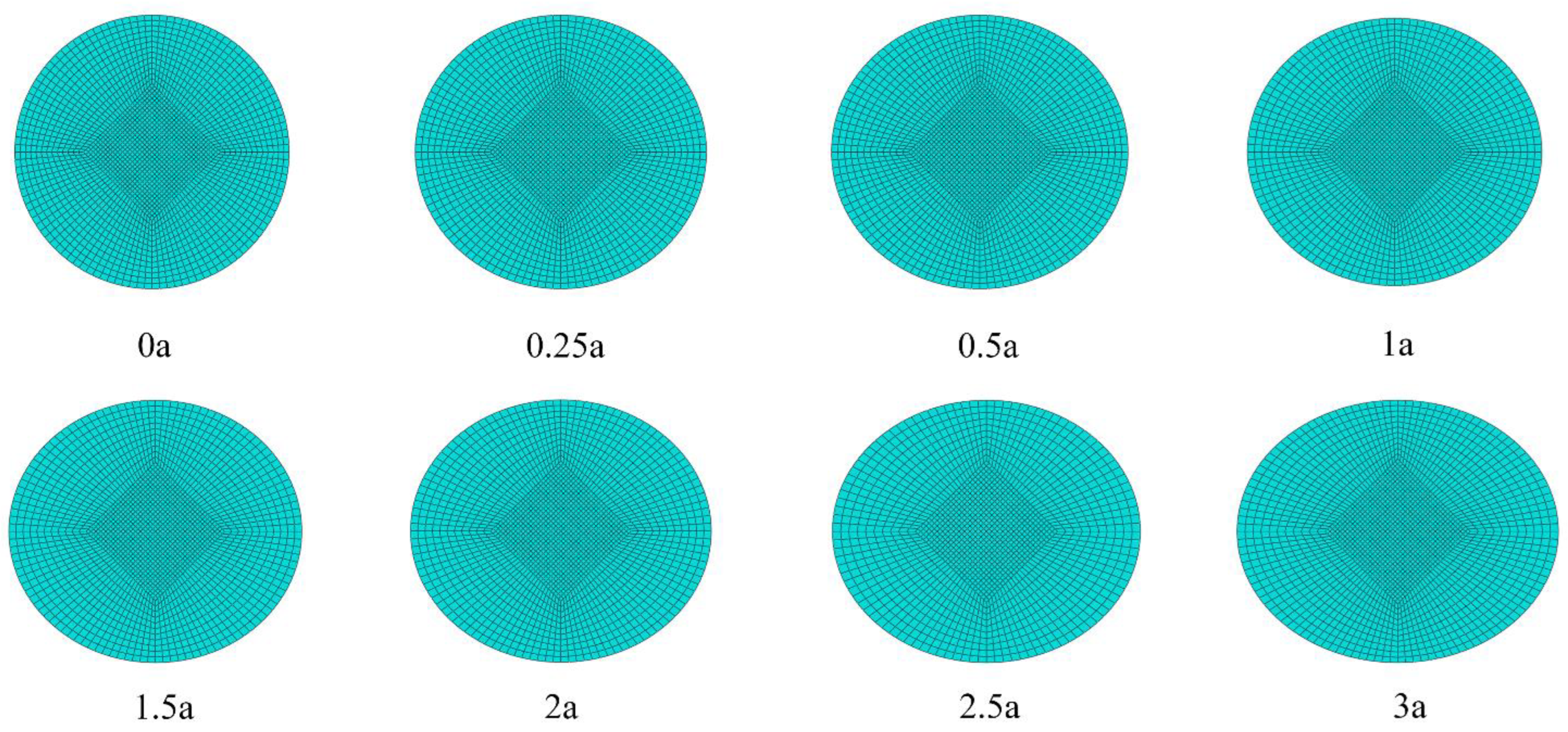
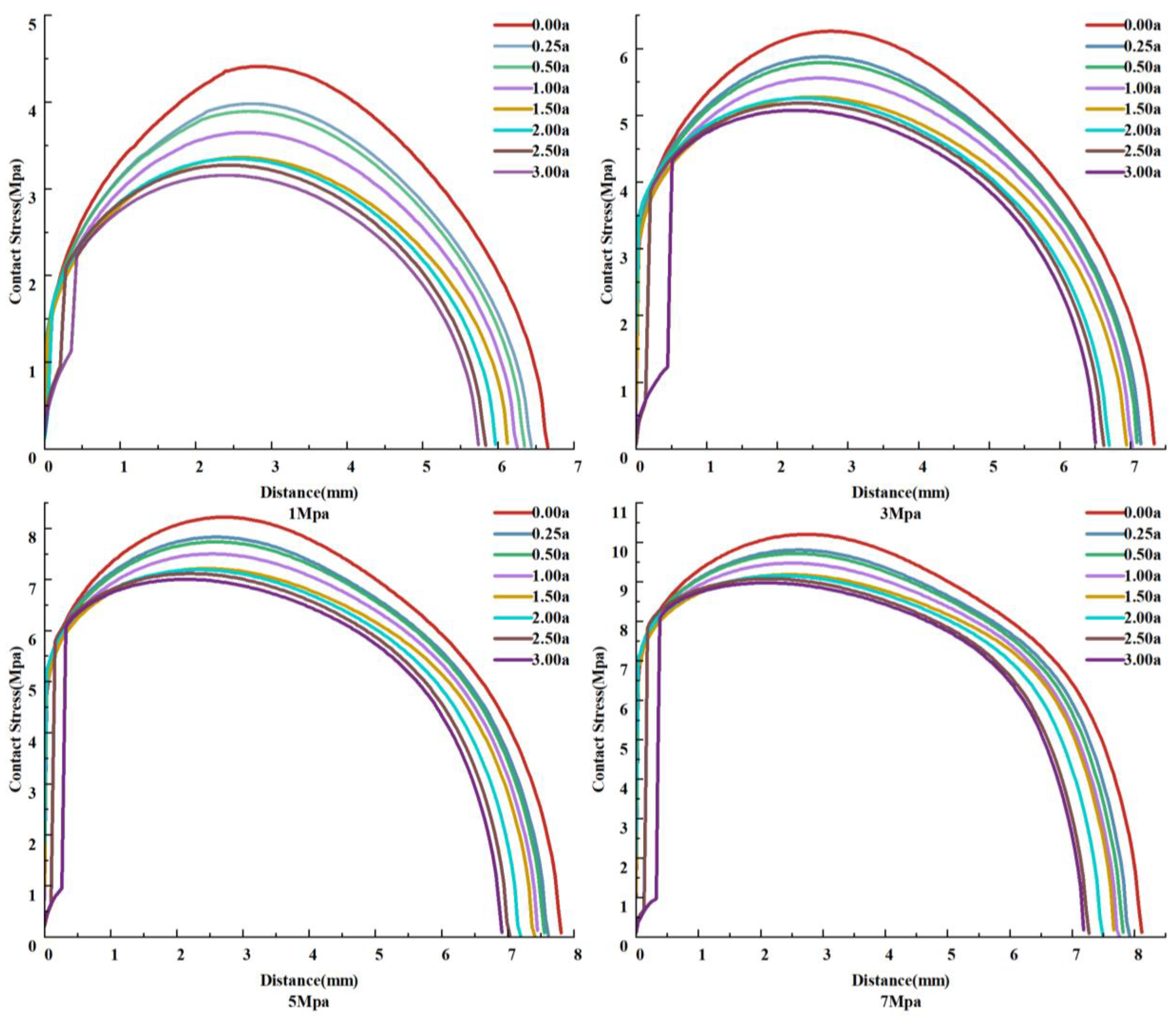
3.3.3. Sealing Performance of Sealing Rings

The sealing performance of the sealing ring is crucial for ensuring the normal operation of the gas generator. The evaluation of the rubber sealing ring’s sealing performance is based on its contact status with the upper and lower flanges. It is observed that a higher contact pressure and longer contact length indicate better sealing performance of the rubber sealing ring.
As a crucial indicator for evaluating the sealing performance, Figure 12 illustrates the distribution of contact pressure along the contact path of the sealing ring under different aging times and gas pressures. The contact pressure varies with changes in the contact path. With increasing gas pressure, the maximum contact pressure of the sealing ring consistently exceeds the gas pressure, and the length of the contact path gradually increases, indicating a good self-sealing effect of the sealing ring. As the sealing ring ages, both the maximum contact pressure and contact length show a significant decrease. In the absence of gas pressure, compared to non-aged sealing rings, there is an 11.7% decrease in maximum contact pressure and a 3.3% decrease in contact length for aged 0.25a sealing rings, while for aged 3a sealing rings, there is a 34.7% decrease in maximum contact pressure and a 14.2% decrease in contact length compared to non-aged ones. This indicates that the aging deformation of rubber seals rapidly reduces their sealing performance.
When the aging degree of the sealing ring is below 2.5a, it can achieve a very short contact length for sealing. However, when the rubber material aged 2.5a, the severe aging and deformation of the sealing ring prevent it from achieving effective sealing in a short path, leading to gas pressure permeating along the contact path. As the aged 3a, this permeation situation becomes even more significant. Although the maximum contact pressure still exceeds the gas pressure at this point, it significantly increases the risk of seal failure.
Considering the impact of aging and deformation on the sealing ring’s performance, it is important to ensure that the sealing ring meets the required standards in both normal and non-aging states. Efforts should be directed towards improving the sealing performance of the sealing ring after aging and deformation, in order to extend its usable life.
The geometric parameters of the sealing structure mainly consist of groove width B, groove depth H, upper rounded corner R1, and lower rounded corner R2. The parameters of the upper and lower rounded corners primarily impact the stress distribution of the sealing ring after extrusion, but do not have any effect on the contact pressure distribution [24]. The depth of the groove primarily impacts the initial compression rate and sealing clearance. The extruded portion of the sealing ring, once compressed, affects the force and contact pressure distribution of the sealing ring. If the sealing clearance is too small, it will increase shear stress under high pressure. Conversely, if the sealing clearance is too large, it will increase the amount of extrusion on the sealing ring and lead to increased wear. The width of the groove affects the bearing capacity of the sealing ring after compression deformation. A narrow groove width may cause unilateral compression of the sealing ring, resulting in a decrease in maximum contact pressure when subjected to air pressure. This could potentially lead to contact separation at a certain air pressure threshold. On the other hand, a wide groove width may cause extensive movement of the sealing ring under high pressure, leading to severe surface wear and potential leakage issues.
Based on the existing sealing structure, structural parameters were designed with groove widths of 11.5, 12.0, 12.5, and 13.0 mm. Analysis revealed that a groove depth of 11.5 mm would result in unilateral compression of the sealing ring. Conversely, a groove depth of 13.0 mm would lead to significant sliding wear, while excessive groove width would cause greater sliding wear during the operation of the non-aged sealing ring.
Furthermore, it was found that a groove depth of 12.0 mm would not result in unilateral compression for the non-aged sealing ring; however, sealing rings with a certain degree of aging may still experience unilateral compression. The sealing ring of different aging degrees has a corresponding suitable sealing groove width, which is caused by the aging deformation of the sealing ring. When the equipment is generally stored for a long time without use and inconvenient to replace or repair, it is advisable to appropriately increase the width of the sealing groove during design to avoid unilateral compression during operation.
When designing the width of the sealing groove, it is important to fully consider the actual storage and usage conditions of the device. Increasing the width of the sealing groove may lead to increased dynamic wear between the seal ring and flange if the equipment is used without long-term storage, resulting in potential increased wear. For the equipment studied in this paper, it is recommended to optimize the structure of the sealing groove and appropriately increase its width. After a comprehensive analysis and careful consideration, the final selected parameters are a slot depth of 7.1 mm and a slot width of 12.5 mm. At this stage, for sealing rings with an aging degree of 3a or below, there will be no unilateral compression, and the equivalent force value will decrease while eliminating pressure permeation. As shown in Figure 13, for non-aged sealing rings, their contact pressure and contact length remain almost unchanged, while the equivalent force value decreases. However, further consideration is needed for the increased groove width causing greater swimming wear.

4. Conclusions

(1)
By constructing a finite element analysis model to study the aging and deformation of seals, it is found that the decrease in contact pressure and contact length caused by the aging deformation of the seal ring gradually leads to the degradation of sealing performance. When considering the geometric boundary deformation of the seal ring, in the absence of gas pressure, the maximum contact pressure of an aged 0.25a seal ring decreased by 11.7% compared to that of an unaged seal ring, and the contact length decreased by 3.3%; for an aged 3a seal ring, compared to an unaged one, the maximum contact pressure decreased by 34.7%, and the contact length decreased by 14.2%. The aging deformation of seal rings is an important factor leading to degradation in sealing performance.
(2)
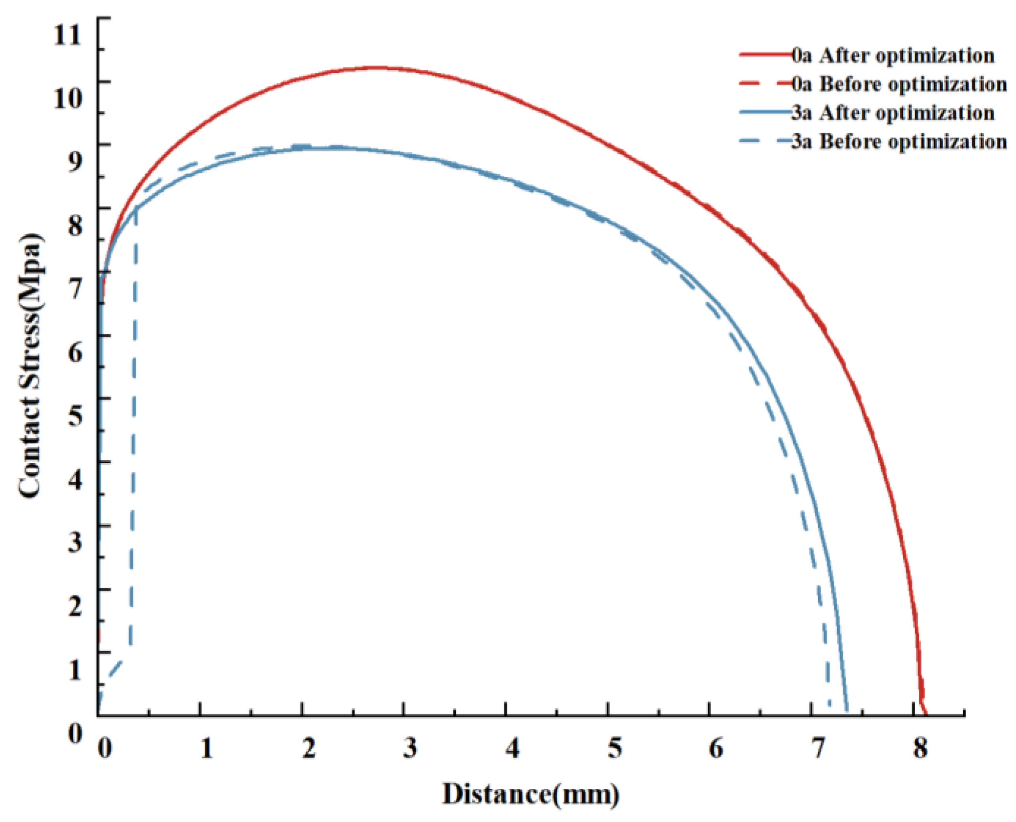
When designing the parameters of the sealing structure, if the sealing ring cannot be replaced for a long time, the width of the sealing groove can be appropriately increased to improve the sealing performance after aging of the sealing ring. Different degrees of aging of the sealing ring correspond to an appropriate width of the sealing groove. If the width is increased too much, it will accelerate wear and tear on lightly aged sealing rings. Therefore, further analysis should be conducted based on actual working conditions.
(3)
Relying solely on the criterion that the maximum contact pressure is greater than the sealing pressure is not accurate enough. The leakage of the seal ring requires not only an analysis of the degradation of contact pressure, but also a further analysis of the formation of leakage channels caused by aging of the rubber seal ring. At the same time, this study made a relatively idealized assumption when considering the aging deformation of the seal ring. It should be further studied to establish a precise model for geometric boundaries driven by physical conditions after rubber seal ring aging over time, combining the degradation model of contact stress and the mechanism for forming leakage channels to fully describe a mechanistic model for leakage caused by the aging deformation of rubber seal rings. Further work in this area is needed.
In fact, in engineering use, special fixtures are required for conducting sealing tests, and if the equipment is not sealed properly, the rubber and fastening devices will need to be redesigned, which consumes a lot of economy and time. Our contribution is to provide a reference for predicting the tightness of equipment by the finite element method. In our finite element prediction, the change of the contact area between rubber and flange seals and the change of mechanical properties of rubber itself are considered in the aging process, which can reflect the real working state of rubber.

Author Contributions

Conceptualization, M.Z. and Y.Z.; methodology, D.M. and M.Z.; software, Y.Z. and M.Z.; formal analysis, M.Z., Y.Z. and Z.S.; investigation, Y.Z. and H.H.; resources, M.Z. and D.M.; data curation, M.Z., H.H. and F.W.; writing—original draft preparation, M.Z., D.M. and H.H.; writing—review and editing, Y.Z. and Z.S.; visualization, M.Z., D.M. and B.L.; supervision, F.W. and B.L.; project administration, M.Z. All authors have read and agreed to the published version of the manuscript.

Funding

This research received no external funding.

Institutional Review Board Statement

Not applicable.

Informed Consent Statement

Not applicable.

Data Availability Statement

The data presented in this study are available on request from the corresponding authors.

Conflicts of Interest

The authors declare no conflicts of interest.

References

  1. Zhu, D.; Lin, Y.; Zhang, H.; Li, Y.; Zeng, D.; Liu, W.; Qiang, C.; Deng, K. Corrosion evaluation of packer rubber materials in CO2 injection wells under supercritical conditions. J. Pet. Sci. Eng. 2017, 151, 311–317. [Google Scholar] [CrossRef]
  2. Zhou, C.; Chen, G.; Liu, P. Finite Element Analysis of Sealing Performance of Rubber D-Ring Seal in High-Pressure Hydrogen Storage Vessel. J. Fail. Anal. Prev. 2018, 18, 846–855. [Google Scholar] [CrossRef]
  3. Zhu, J.; Li, X.; Beamish, S.; Dwyer-Joyce, R.S. An ultrasonic method for measurement of oil films in reciprocating rubber O-ring seals. Tribol. Int. 2022, 167, 107407. [Google Scholar] [CrossRef]
  4. Lian, Y.Q.; Li, C.L.; Li, Z.J. Underwater rubber elastic launch torpedo interior ballistic simulation. J. Nav. Eng. Univ. 2016, 28, 100–106. [Google Scholar]
  5. Cam, J.B.L.; Huneau, B.; Verron, E.; Gornet, L. Mechanism of Fatigue Crack Growth in Carbon Black Filled Natural Rubber. Macromolecules 2004, 37, 5011–5017. [Google Scholar] [CrossRef]
  6. Beurrot, S.; Huneau, B.; Verron, E. In situ SEM study of fatigue crack growth mechanism in carbon black-filled natural rubber. J. Appl. Polym. Sci. 2010, 117, 1260–1269. [Google Scholar] [CrossRef]
  7. Shi, C.; Cao, C.; Lei, M.; Peng, L.; Shen, J. Time-dependent performance and constitutive model of EPDM rubber gasket used for tunnel segment joints. Tunn. Undergr. Space Technol. 2015, 50, 490–498. [Google Scholar] [CrossRef]
  8. Liu, J.; Li, X.; Xu, L.; He, T. Service lifetime estimation of EPDM rubber based on accelerated aging tests. J. Mater. Eng. Perform. 2017, 26, 1735–1740. [Google Scholar] [CrossRef]
  9. Li, C.; Ding, Y.; Yang, Z.; Yuan, Z.; Ye, L. Compressive stress-thermo oxidative ageing behaviour and mechanism of EPDM rubber gaskets for sealing resilience assessment. Polym. Test. 2020, 84, 106366. [Google Scholar] [CrossRef]
  10. Mei, Y.; Yi-min, X.; Yong, R.; Zhang, B.; Wang, Y. Design of O-ring with skeleton seal of cutter changing robot storage tank gate for large diameter shield machine. Tribol. Int. 2023, 185, 108591. [Google Scholar]
  11. Xie, C.J.; Huang, X.; Zhang, X.Z.; Jin, G.L.; Zhang, J.Q. Correlating the time-dependent behavior of EPDM gaskets with the long-term sealant performance of gasketed joints in shield tunnels. Constr. Build. Mater. 2024, 419, 135526. [Google Scholar] [CrossRef]
  12. Jiguang, J.; Xiaotian, L.; Chengzhi, S.; Xiaolong, H.; Kun, Q. The performance of double-layer rubber sealing ring under the action of low temperature environment. Vibroengineering Procedia 2023, 48, 120–125. [Google Scholar]
  13. Liu, W.; He, G. Storage life of silicone rubber sealing ring used in solid rocket motor. Chin. J. Aeronaut. 2014, 27, 1469–1476. [Google Scholar] [CrossRef]
  14. Hang, L.; Jian, W.; Fei, T.; Benlong, S.; Haohao, L. Multiscale simulation on dynamic friction behavior of cylinder sealing rings under hydrothermal aging. J. Appl. Polym. Sci. 2021, 138, 50453. [Google Scholar]
  15. GB/T 7759-2015; Determination of Compression Set at Room Temperature, High Temperature, and Low Temperature for Vulcanized Rubber and Thermoplastic Rubber. China Standard Press: Beijing, China, 2015.
  16. Zhang, J.; Li, Q.; Zhang, C.; An, P.; Yan, Y. High-temperature sealing performance and structure optimization of rubber core for conical blowout preventer. Geoenergy Sci. Eng. 2024, 234, 212606. [Google Scholar] [CrossRef]
  17. Chao, Z.; Xuefei, Z.; Jie, Q.; Peng, L.; Abulimiti, A. Nonlinear finite element analysis on the sealing performance of rubber packer for hydraulic fracturing. J. Nat. Gas Sci. Eng. 2021, 85, 103711. [Google Scholar]
  18. Zhang, Q.; Meng, G.; Geng, H.; Suo, S.; Zhang, J. Finite element analysis of silicone rubber based on Yeoh constitutive model and Ogden constitutive model. IOP Conf. Ser. Earth Environ. Sci. IOP Publ. 2021, 714, 032078. [Google Scholar] [CrossRef]
  19. Huang, Y.; Li, Y.; Zhao, H.; Wen, H. Research on constitutive models of hydrogenated nitrile butadiene rubber for packer at different temperatures. J. Mech. Sci. Technol. 2020, 34, 155–164. [Google Scholar] [CrossRef]
  20. Li, K.; Shi, W.; Ding, H.; Chen, Z. Research of thermal oxygen ageing on tensile properties of rubber based on Peck-Yeoh model. Mater. Res. Express 2021, 8, 065303. [Google Scholar] [CrossRef]
  21. Mooney, M. A theory of large elastic deformation. J. Appl. Phys. 1940, 11, 582–592. [Google Scholar] [CrossRef]
  22. Rivlin, R. Large elastic deformation of isotropic matcrials, I. Fundamental concepts, II. Some uniqueness theories for pure homogeneous deformations. Philos. Trans. R. Soc. Lond. Ser. A 1948, 240, 459–508. [Google Scholar]
  23. Gu, Z.; Guo, F.; Tan, G.; Xiang, C.; Zhang, L. Study on the influence of rubber O-ring aging on sealing performance based on fluid structure coupling. Lubr. Seal. 2023, 48, 21–26. [Google Scholar]
  24. Ren, Q.; Cai, T.; Wang, R.; Hu, D. Research on structural parameters and failure criteria of rubber O-shaped sealing rings. Solid Rocket Technol. 2006, 1, 9–14. [Google Scholar]
Figure 1. Simplified structure of a gas generator.
Coatings 14 01178 g001
Figure 2. High Temperature Aging Chamber and Testing Fixture.
Coatings 14 01178 g002
Figure 3. Sample degradation trajectory and linear fitting. (a) Compress permanent deformation data. (b) Linear fitting results.
Coatings 14 01178 g003
Figure 4. Activation Energy in Different Temperature Ranges.
Coatings 14 01178 g004
Figure 5. Universal testing machine and stress–strain curve.
Coatings 14 01178 g005
Figure 6. Yeoh model parameters of the unaged and aged rubber under compression as functions of aging time.
Coatings 14 01178 g006
Figure 7. Finite element analysis model.
Coatings 14 01178 g007
Figure 8. Changes in physical cross-section with aging time.
Coatings 14 01178 g008
Figure 9. Distribution of contact pressure of sealing ring along contact length under different air pressures. (a) Equivalent aging 3a sealing ring, whether cross-sectional deformation is considered. (b) Equivalent aging 3a sealing ring and non-aging sealing ring, without considering cross-sectional deformation.
Coatings 14 01178 g009
Figure 10. The state of the unaged sealing ring under different gas pressures.
Coatings 14 01178 g010
Figure 11. State of aging 3a sealing ring under different gas pressures.
Coatings 14 01178 g011
Figure 12. Distribution of contact pressure along the contact length of sealing rings with different degrees of aging under gas pressure.
Coatings 14 01178 g012
Figure 13. Distribution of contact pressure along the contact length of the sealing ring before and after optimization under 7 Mpa air pressure.
Coatings 14 01178 g013
Table 1. Correspondence between Storage Time and Acceleration Time at 80 °C.
Equivalent Storage
time/a (25 °C)
0.250.501.001.502.002.503.00
Compress
deformation %
10.2813.4818.8223.3727.4031.0434.38
Accelerated aging
Time/h
193876114152189228
Table 2. Yeoh model parameters.
Equivalent Aging Degree/a C 1 /MPa C 2 /MPa C 3 /MPa
0.001.104050.021540.46121
0.251.125580.031650.67724
0.501.166380.033320.70538
1.001.188400.035640.76096
1.501.156460.037210.79654
2.001.240070.047230.88921
2.501.298820.045130.86855
3.001.320270.043730.92095
Table 3. Verification of grid independence for unaged sealing rings and air pressure of 1 Mpa.
NodesMax Contact
Stress/MPa
Error %Max Mises
Stress/MPa
Error %
40284.397-3.472-
89494.4040.163.4770.14
16,6924.4070.073.4790.06
Disclaimer/Publisher’s Note: The statements, opinions and data contained in all publications are solely those of the individual author(s) and contributor(s) and not of MDPI and/or the editor(s). MDPI and/or the editor(s) disclaim responsibility for any injury to people or property resulting from any ideas, methods, instructions or products referred to in the content.

