Article

Evaluation of Magnetron Sputtered TiAlSiN-Based Thin Films as Protective Coatings for Tool Steel Surfaces

by
Magdalena Valentina Lungu
1,*,
Dorinel Tălpeanu
1,
Romeo Cristian Ciobanu
2,*,
Anca Cojocaru
3,
Delia Pătroi
1,
Virgil Marinescu
1 and
Alina Ruxandra Caramitu
1
1
National Institute for Research and Development in Electrical Engineering ICPE—CA Bucharest, Splaiul Unirii No. 313, Sector 3, 030138 Bucharest, Romania
2
Department of Electrical Measurements and Materials, Gheorghe Asachi Technical University, 700050 Iasi, Romania
3
Faculty of Chemical Engineering and Biotechnologies, National University of Science and Technology Politehnica Bucharest, 1–7 Gh. Polizu Street, 011061 Bucharest, Romania
*
Authors to whom correspondence should be addressed.
Coatings 2024, 14(9), 1184; https://doi.org/10.3390/coatings14091184
Submission received: 16 August 2024 / Revised: 8 September 2024 / Accepted: 10 September 2024 / Published: 12 September 2024
(This article belongs to the Special Issue Magnetron Sputtering Coatings: From Materials to Applications)

Abstract

:
Steel surface protection with hard coatings is essential in metalworking, yet developing high-performance coatings is challenging. TiAlSiN coatings grown on various substrates using commercial targets have been extensively studied, but consistent data on their properties are lacking. This study focused on TiAlSiN single layers (SL) and TiAlSiN/TiN bilayers (BL), with an 800 nm thick TiAlSiN top layer and a 100 nm thick TiN mid layer. These coatings were grown on C120 tool steel discs via reactive DC magnetron sputtering using TiAlSi 75–20–5 at.% and Ti targets fabricated in-house through spark plasma sintering. The stability of coatings was assessed after thermal treatment (TT) in air at 800 °C for 1 h. SEM analysis revealed a columnar microstructure with pyramidal grains in the SL and BL coatings, and coarser pyramidal and prismatic grains in both TT coatings. EDS analysis showed a decrease in Ti, Al, Si, and N content after annealing, while O content increased due to oxide formation. High indentation hardness (9.19 ± 0.09 GPa) and low effective elastic modulus (148 ± 6 GPa) were displayed by the BL TT coating, indicating good resistance to plastic deformation and better load distribution. The highest fracture toughness was noted in the BL TT coating (0.0354 GPa), which was 16.4 times greater than the steel substrate. Better scratch resistance and low coefficient of friction (COF ≤ 0.35) were exhibited by both TT coatings. Tribological tests showed a mean COF of 0.616–0.773, comparable to the steel substrate (0.670). The lowest corrosion current density (0.1298 µA/cm²), highest polarization resistance (46.34 kΩ cm²), and a reduced corrosion rate (1.51 µm/year) in a 3.5 wt.% NaCl solution was also exhibited by the BL TT coating. These findings indicate TiAlSiN/TiN films as effective protective coatings for tool steel surfaces.

1. Introduction

Various types of wear can be experienced by metal cutting tools during operation, such as abrasive and adhesive wear, cracking, breaking, chipping, and plastic deformation [1,2,3]. While surface wear is mainly influenced by abrasive and adhesive mechanisms, the other types of wear mentioned above typically affect bulk materials. Contact fatigue wear is caused by microscopic defects in the material and surface imperfections from mechanical processing [2,3]. These types of wear arise from the interactions between the cutting tool, workpiece, and environment [1,4]. To address these issues, wear-resistant coatings are applied to tailor both bulk and surface properties for specific applications.
Wear resistance can be enhanced by altering the surface material or its topography through thermal or chemical treatments, or by adding surface layers with distinct properties. The surface layers can be formed as a single layer, a multilayer, a functionally graded structure, or a composite layer incorporating elements from different materials [5]. The operational behavior, lifespan, and performance of metal cutting tools can be improved, and material consumption reduced, by depositing wear-resistant coatings on the tools [6].
For effective wear prevention, the nature and properties of the substrate material, heat treatment processes, and surface conditions must be taken into account, along with the characteristics of the hard coatings applied [6]. High hardness and toughness [7,8], superior wear resistance [7], strong adhesion [8], as well as mechanical, thermal and chemical stability [7], must be exhibited by such protective coatings, particularly in dry environments. Additionally, a low coefficient of friction and low thermal conductivity of both the substrate and coatings are required to minimize heating and wear [9,10], and to prevent galling [11]. High corrosion resistance [10], good uniformity and low porosity to prevent defects such as pitting corrosion [10] are also necessary in wet environments.
For tool steel components such as dies and punches, it is necessary that the bare or coated surfaces are prevented from adhering to each other. Thermal stability is considered critical, as the coated components are exposed to high temperatures during dry mechanical processing [11]. The adhesion of coatings to the steel substrate is mainly influenced by the temperature, flatness, and surface roughness of the substrate [8,12].
Surface hardening techniques, such as physical vapor deposition (PVD), chemical vapor deposition (CVD), and thermochemical methods, are commonly used for the application of protective coatings on tool surfaces [13,14,15]. PVD techniques like magnetron sputtering (DC and RF), reactive sputtering with nitrogen or oxygen gas [14,16,17,18,19], arc ion plating [20,21,22], thermal vacuum evaporation [15], and plasma spraying [23,24] are widely employed. Generally, hard coatings are deposited at maximum temperatures of 1000 °C using CVD methods and 500 °C using PVD methods, with resulting thicknesses of over 20 µm for CVD coatings and up to 10–15 µm for PVD coatings [25].
Coatings like TiC, TiCN, TiN, and Al₂O₃ were first produced on an industrial scale using CVD methods in the 1970s [19]. The development of TiN and TiCN coatings by PVD methods in the 1980s and 1990s led to the realization of more advanced coatings, such as TiAlN, TiSiN, and TiAlSiN, with improved performance in challenging environments [26]. PVD coatings with thicknesses of 0.5–4 µm are reported to be applied on metal cutting tools and components requiring protection from corrosion and erosion [25,26].
The quality of coatings is strongly influenced by the chemical composition of deposition materials, the equipment used, and the working parameters [1,2,25]. Mechanical strength, crack resistance, and elastic modulus are enhanced by adding 25–75 at.% Al to TiAl alloys, while density is reduced. The allotropic transformation temperature of Ti is also increased by Al [27]. In TiAl alloys, and TiAlN coatings, oxidation and creep resistance, thermal stability, and mechanical and tribological properties are improved by the addition of 5–10 at.% of elements like Si, Cr, Nb, Mo, and W [15].
The performance of coatings is dependent on the substrate surface quality, pre- and post-deposition treatments, and the composition, structure, and thickness of the coatings [28,29,30,31]. Research studies have revealed that superior mechanical and wear-resistant properties are exhibited by multilayer and compositional gradient coatings compared to single-layer coatings, making them more suitable for demanding applications [13,16].
While TiN coatings are widely used as protective coatings on various metallic substrates, a high substrate temperature is required to achieve sufficient adhesion strength. Moreover, oxidation of TiN coatings begins at around 550 °C [32]. These limitations have led to the exploration of ternary and quaternary coatings, such as TiAlN, TiSiN [6,13,25], and TiAlSiN [17,33,34], which provide improved oxidation resistance up to 950 °C. Superior oxidation resistance at 850–1000 °C was exhibited by Ti0.5Al0.4Si0.1N coatings compared to Ti0.5Al0.5N coatings, as the addition of Si into TiAlN increased the Al diffusion coefficient and led to the formation of a combined Al2O3 and SiO2 barrier layer during oxidation [35].
Although TiAlN and TiSiN coatings exhibit good mechanical properties and oxidation resistance up to 700 °C, their adhesion can diminish at higher temperatures, leading to potential failures during operation [13]. Fuentes et al. [33] have disclosed that the wear behavior of TiAlSiN coatings up to 600 °C was affected significantly by the coating composition and testing temperature. Given that the operating temperature for high-speed dry cutting with TiAlSiN-based coated tools often exceeds 600 °C, further research is needed to optimize these coatings for high-temperature applications [13,20,34].
TiAlSiN coatings were prepared by Zhou et al. [20] using a cathode arc ion process with Ti, Al0.67Ti0.33 and Ti0.8Si0.2 targets. The microstructure, mechanical, and tribological properties were studied at room temperature (RT) and after annealing at 200 °C, 400 °C, 600 °C, and 800 °C. The findings revealed that annealing temperature greatly affected the elemental composition, with an increase in oxygen content at higher temperatures. Additionally, the formation of oxides such as Ti-O, Al-O, and Si-O acted as lubricants, reducing the shear resistance and the coefficient of friction for the coatings annealed above 600 °C.
TiAlSiN films, with a composition of Ti0.5Al0.2Si0.05N0.5 and a thickness of ~200 nm, were deposited by Rahman et al. [36] on AISI M2 high-speed tool steel substrates using reactive magnetron sputtering, with Ti, Al, and Si targets. The films maintained good structural and morphological stability after annealing in air at temperatures up to 800 °C.
Commercial sputtering targets made of pure Ti, Al, and Si, as well as TiAl, AlSi, and TiAlSi alloys, are utilized in most research studies to deposit TiAlSiN coatings via reactive magnetron sputtering on various substrates, such as AISI H11 (1.2343) hot work tool steel [37], AISI M2 high-speed steel [38], Si (100) and WC steel [19], and cemented carbide [39].
In this study, TiAlSiN-based coatings were deposited on C120 tool steel discs via reactive DC magnetron sputtering. Innovative TiAlSi 75–20–5 at.% and Ti targets, fabricated in-house through spark plasma sintering, were used for deposition, resulting in TiAlSiN and TiAlSiN/TiN thin films with higher and more stable deposition rates over the long term. Superior microstructure, mechanical, tribological, and electrochemical properties were exhibited by the TiAlSiN/TiN coatings, especially after thermal treatment in air at 800 °C for 1 h, indicating their potential as protective coatings for tool steel surfaces.

2. Materials and Methods

2.1. Materials

Disc-shaped samples of C120 tool steel, equivalent to 205Cr115 and X210Cr12 (1.2080), with diameters of 28 mm and 14 mm and a thickness of 1 mm were used as substrates for thin film deposition. The following chemical composition (wt.%) is reported in this tool steel grade: 1.9–2.2% C, 0.1–0.4% Si, 0.15–0.45% Mn, 11–12% Cr, max. 0.35% Ni, and the balance Fe, according to the EN ISO 4957:2018 standard [40].
The disc-shaped TiAlSi 75–20–5 at.% and Ti sputtering targets were fabricated by INCDIE ICPE-CA Bucharest, Romania using a spark plasma sintering (SPS) installation of HP D25 type (FCT Systeme GmbH, Rauenstein, Germany), as described elsewhere [27,41]. The main characteristics of the targets are shown in Table 1 and Figure 1.

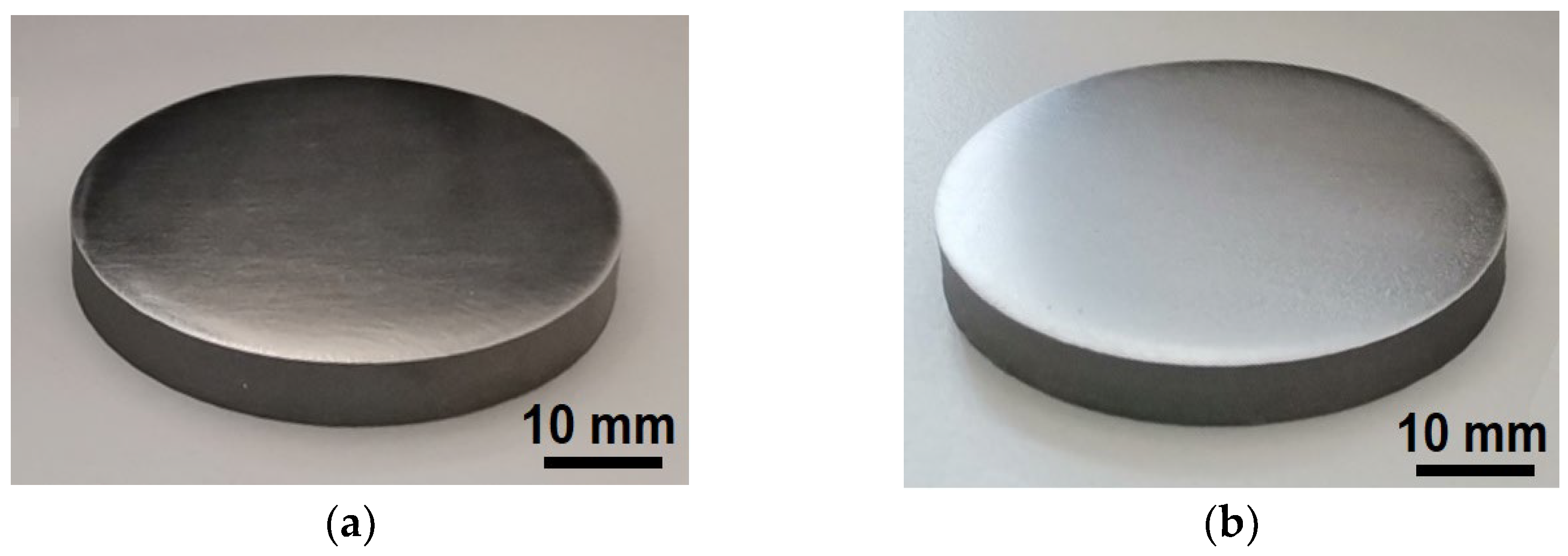
2.2. Steel Substrate Preparation

The tool steel substrate samples were cut by wire erosion from cylindrical bars with diameters of 14 mm and 28 mm using a CNC Electric Discharge Machine Smart DEM (Knuth, Wasbek, Germany). They were then ground into disc-shaped samples with flat, parallel surfaces and a thickness of 1 mm. The surfaces of steel discs were chemically cleaned with orthophosphoric acid, followed by washes with distilled water, a 1% w/v Na2CO3·10H2O alkaline solution, and further washes with distilled water and acetone. Afterward, the surfaces of the steel discs were polished to a mirror finish with alumina using a LaboPol-5 (Struers, Ballerup, Denmark) grinding machine to achieve smooth surfaces and to reduce frictional heating under dry sliding conditions. Finally, the steel discs were washed with distilled water and subsequently with ethyl alcohol.

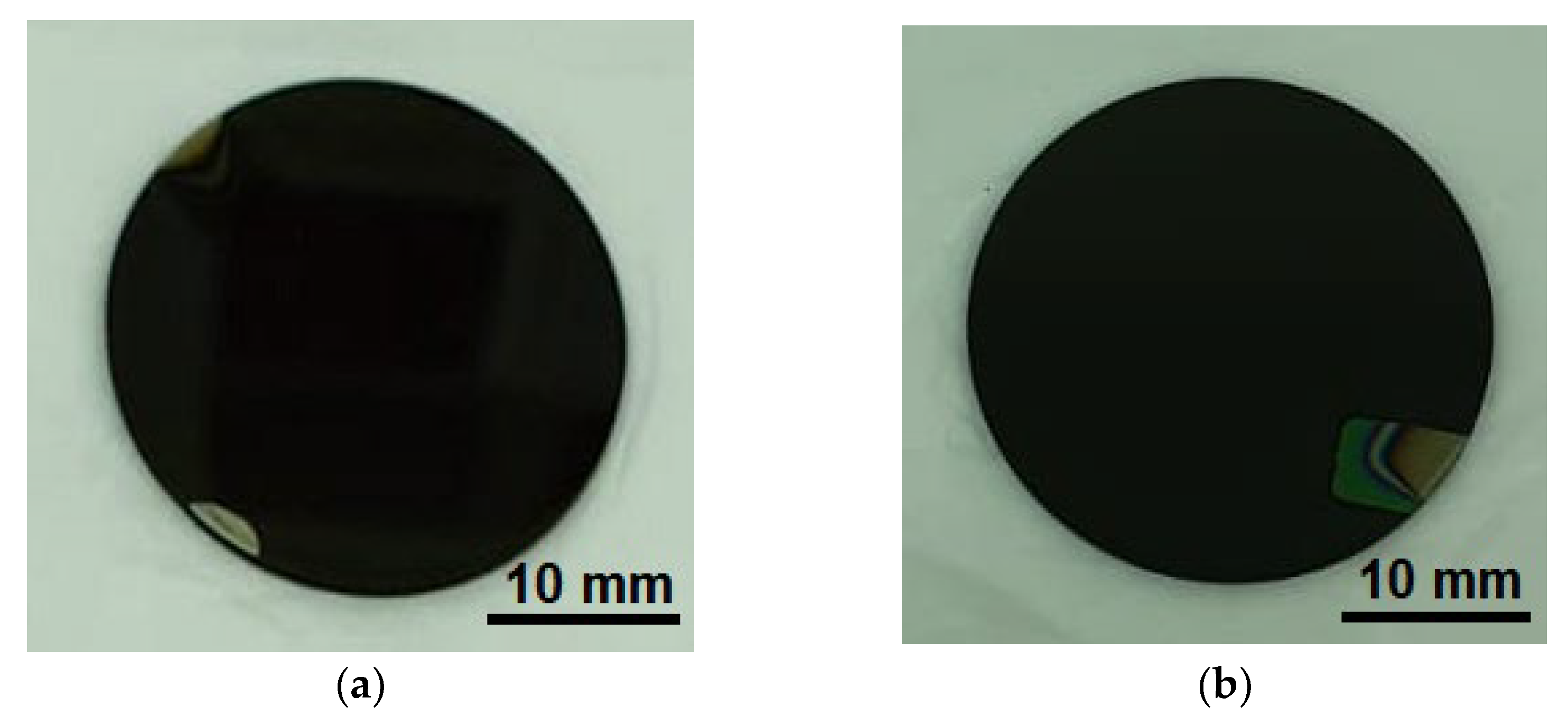
2.3. Thin Film Deposition

The deposition of TiAlSiN and TiN thin film coatings on C120 steel substrates was carried out by DC magnetron sputtering using a vacuum installation (Bestec GmbH, Berlin, Germany). The deposition conditions are presented in Table 2.
The deposition rate and layer thickness were monitored in real time with a system consisting of an FTM-2000 controller (Torr International Inc., New Windsor, New York, NY, USA), an oscillator, a quartz crystal sensor with gold contacts of IAD 6MHz Au type (Evatec, Trübbach, Switzerland) mounted in the vacuum chamber close to the samples, and a controller-oscillator connection cable (Figure 2).
The single-layer TiAlSiN coatings were coded as SL, and the bilayer TiAlSiN/TiN coatings as BL. Thermal treatment (TT) in air at 800 °C for 1 h was applied to a part of SL and BL samples using a N7/H oven (Nabertherm GmbH, Lilienthal, Germany) to study the aging behavior in terms of mechanical, tribological, and electrochemical properties. The thermally treated samples were coded as SL TT and BL TT, respectively.

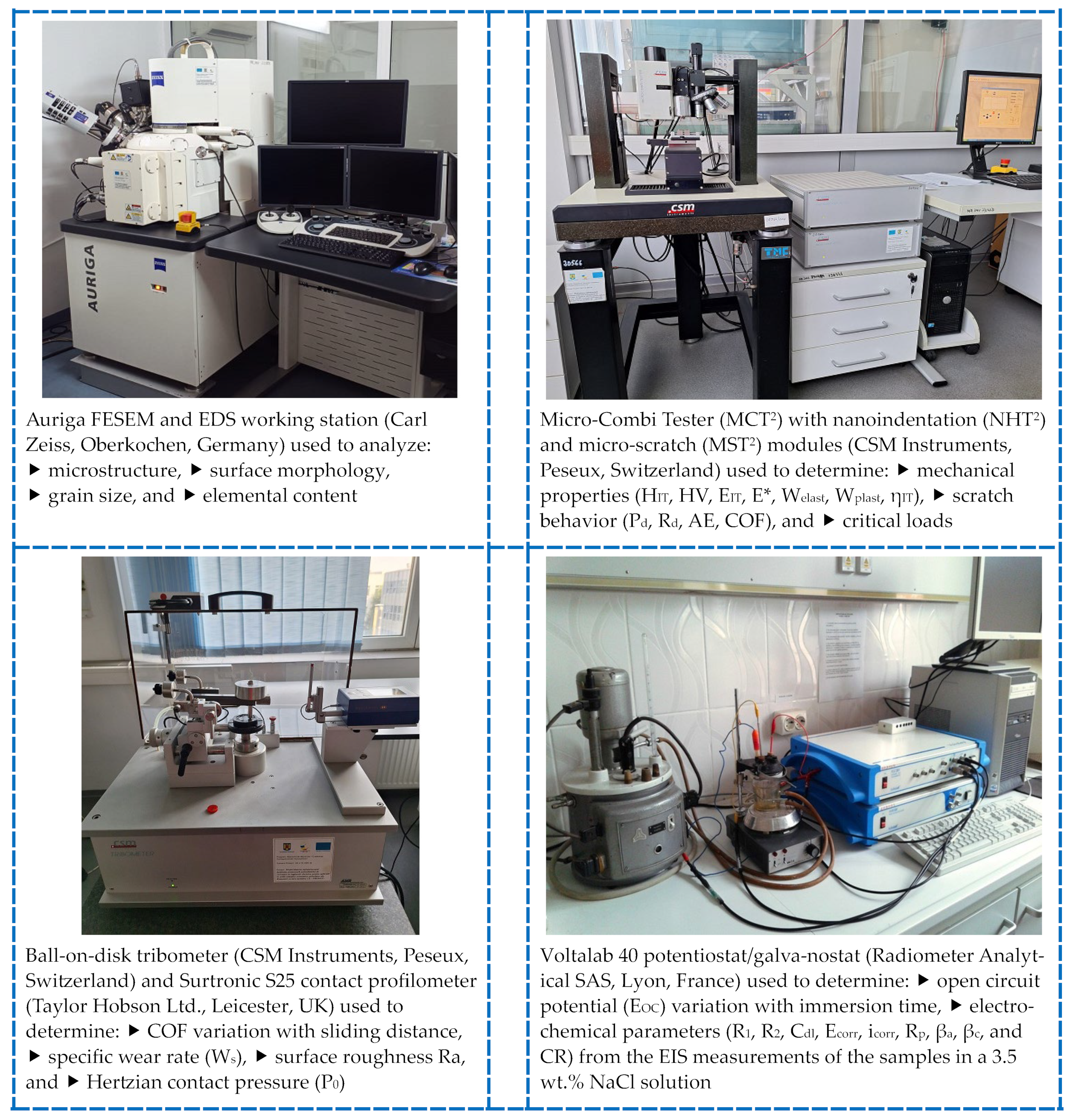
2.4. Investigation Methods and Equipment

The as-deposited and thermally treated coatings were investigated using a separate sample of each type for every test.
The equipment used for the investigation of the samples through SEM and EDS analysis, as well as mechanical, tribological, and electrochemical tests, is shown in Figure 3.

2.4.1. SEM and EDS Analysis

SEM and EDS analysis of the TiAlN-based coatings was performed using an Auriga Field Emission Scanning Electron Microscope (FESEM) (Carl Zeiss, Oberkochen, Germany), equipped with a Canion focused ion beam (FIB) column (Orsay Physics, Fuveau, France), and a X-MaxN Energy Dispersive Spectroscopy (EDS) Silicon Drift Detector (SDD) sensor with Aztec 3.0 software (Oxford Instruments plc, Abingdon, UK) (Figure 3).
The SEM images and EDS data were acquired using the InLens or Secondary Electron Scintillator Imaging (SESI) detector (Carl Zeiss, Oberkochen, Germany) at magnifications of 20,000×, 50,000×, 100,000×, or 200,000× with acceleration voltages of 5 kV or 10 kV.

2.4.2. Nanoindentation Testing

The indentation hardness (HIT), Vickers hardness HV, indentation elastic modulus (EIT), effective elastic modulus (E*), elastic reverse and plastic deformation work of indentation (Welast and Wplast), and elastic part of indentation work (ηIT) of the TiAlN-based coatings and C120 tool steel substrate (Ø28 mm × 1 mm) were determined by instrumented nanoindentation testing using the Indentation 4.37 software and the Oliver and Pharr calculation method [42], in accordance with the ISO standards 14577-1:2015 [43] and 14577-4:2016 [44].
Mechanical tests were conducted at RT (25 ± 2 °C) and 35 ± 3% relative humidity using the nanoindentation module (NHT2) with a diamond Berkovich indenter mounted on the Micro-Combi Tester (MCT2) platform (CSM Instruments, Peseux, Switzerland) (Figure 3). The measurement conditions are shown in Table 3. Ten measurements were performed on each sample in advanced mode, with depth control (maximum depth of 1/10 of coating thickness) for the TiAlSiN-based thin film coatings and load control for the C120 tool steel substrate. The mean and standard deviation (SD) values of the obtained mechanical properties are reported.

2.4.3. Micro-Scratch Tests

Micro-scratch tests of the TiAlSiN-based coatings deposited on C120 tool steel substrates (Ø28 mm × 1 mm) were performed using the micro-scratch module (MST2) and a Rockwell diamond indenter with a radius of 100 µm, a video microscope with a 20× magnification objective lens, and specific sensors for measuring acoustic emission (AE), penetration depth (Pd), and coefficient of friction (COF), all mounted on the MCT2 platform (CSM Instruments, Peseux, Switzerland) (Figure 3). The tests were conducted at RT (25 ± 2 °C) and 35 ± 3% relative humidity, according to the ASTM C1624-22 standard [45] and ISO 20502:2005 standard [46], under a linear progressive scratching load from 0.03 N to 30 N, a constant scratching speed of 6 mm/min, a scratch length of 3 mm, a loading rate of 60 N/min, and a scanning contact load of 30 mN. The optical, Pd, and AE critical loads (Lc), defined as the smallest loads at which visible defects appeared in the coatings, were determined from the recorded curves and images acquired through optical analysis of the scratch tracks using the Scratch 4.37 software with Panorama feature and Video 4.05 software.

2.4.4. Tribological Tests

Tribological tests were conducted on TiAlSiN-based coatings/steel and a C120 steel substrate (Ø28 mm × 1 mm) at RT (25 ± 2 °C) and 35 ± 3% relative humidity, using a ball-on-disk tribometer equipped with a rotating module (CSM Instruments, Peseux, Switzerland) (Figure 3). The variation of the coefficient of friction (COF) was recorded under dry sliding conditions, using a constant normal load (Fn) of 5 N (deadweight) applied to the tested sample, with a Ø6 mm alumina (Al2O3) ball as the static partner held in contact with the rotating disc-shaped sample by the Fn. The tribometer operated at a constant linear speed of 3 cm/s, with a sliding radius (R) of 9 mm, and a sliding distance (D) of 50 m (about 885 laps). The Al2O3 ball had a Vickers hardness HV30 of 1970, and an elastic modulus of 300 GPa [47,48]. The tribological tests were conducted according to the ASTM G99-17 standard [49] using an unworn ball for each test. The deflection of the static partner was measured for load and recorded as a tangential load (Ft). The coefficient of friction (µ) was calculated as the ratio of Ft to Fn using Equation (1) [50]:
µ = F t F n
The plots for variation in COF (µ) were recorded versus sliding distance using the TriboX 4.1.I software. The specific wear rate (Ws), expressed in mm³/(N·m), was calculated by measuring the volume of track material removed (V, in mm3) and normalizing that to the load (Fn, in N) and the sliding distance (D, in m) performed during the tribological test, as shown in Equation (2) [50]:
W s = V F n · D
After the tribological tests were completed, a line scan was performed across the worn track of each sample over an evaluation length of 4 mm, a cut-off of 0.8 and a Gaussian filter, using a Surtronic S25 profilometer (Taylor Hobson Ltd., Leicester, UK) equipped with a right-angle pick-up and a 5 µm stylus tip radius (Figure 3). The volume of material removed from the track was calculated by multiplying the area of the recorded wear track profile by the circumference of the wear track [50]. The profilometer was connected to the CSM tribometer and its data acquisition system for the calculation of the Ws values.
The surface roughness Ra of the samples was determined using the same contact profilometer and under similar measurement conditions as described above.

2.4.5. Corrosion Tests

Corrosion tests were performed using open circuit potential (OCP), potentiodynamic polarization (PDP), and electrochemical impedance spectroscopy (EIS). A 3.5 wt.% NaCl aqueous solution was used as the corrosion testing solution (electrolyte).
Electrochemical studies were conducted with a Voltalab 40 potentiostat/galvanostat (Radiometer Analytical SAS, Lyon, France), which was interfaced with a computer and used with VoltaMaster 4.0 software for data acquisition and processing (Figure 3). The tests were carried out at 25 ± 2 °C in a three-electrode electrochemical cell. The studied sample was used as the working electrode (with an exposed surface of 8 mm in diameter and an area of about 50.27 mm2), a platinum mesh electrode was used as the auxiliary electrode, and a saturated Ag/AgCl electrode was used as the reference electrode, which was directly immersed in the electrolyte. All potentials were reported relative to this reference electrode.
Before the polarization and EIS measurements, the working electrode was kept in the 3.5 wt.% NaCl solution for 20 min to reach the OCP. The PDP experiments were performed at a scan rate of 1 mV/s, starting from a cathodic potential and progressing in the anodic direction, within the potential range of −800 mV to +800 mV versus OCP.
The EIS method is used to study the response of the system to the application of a small amplitude alternating current (AC) signal, which provides information related to the interface and the reactions occurring at the interface. Therefore, the EIS measurements were conducted at the open circuit potential (EOC) within the frequency range of 100 kHz to 100 mHz, with a sinusoidal potential perturbation of 10 mV in amplitude. The electrochemical parameters obtained from the processing of the PDP curves included the corrosion potential (Ecorr), corrosion current density (icorr), anodic and cathodic Tafel slopes (βa and βc, respectively), and polarization resistance (Rp), which were determined through Tafel extrapolation of the linear regions. The impedance parameters evaluated from the Nyquist plots recorded at the OCP included the charge transfer resistance (Rct), which indicates corrosion resistance and the double-layer capacitance (Cdl).

3. Results and Discussion

The macrographic aspect of the TiAlSiN-based coatings deposited on C120 steel substrate with diameter × thickness of 28 mm × 1 mm is shown in Figure 4.
In both images shown in Figure 4, uniform and homogeneous coatings, free of defects such as cracks and voids, were observed by the naked eye. Additionally, good adherence of all the synthesized thin film coatings to the base material (C120 tool steel substrate and TiN film/steel) was exhibited.

3.1. SEM and EDS Analysis

The smooth surface of the polished C120 tool steel substrate is displayed in Figure 5.
The morphology of the top surface of the thin film coatings grown on C120 tool steel substrate was observed by SEM analysis as illustrated in Figure 6 and Figure 7.
The InLens detector (Carl Zeiss, Oberkochen, Germany) was used for studying the as-deposited coatings with fine surface structures, while the SESI detector (Carl Zeiss, Oberkochen, Germany) was used for thermally treated coatings with coarser grain microstructures, as it is more sensitive to the overall surface of the sample.
A columnar structure with pyramidal-shaped grains measuring several tenths of a nanometer in size was exhibited by the as-deposited TiAlSiN coatings (SL and BL) (Figure 6). No structural defects, such as cracks, were observed in these coatings. Columnar grain structures are commonly observed in thin films grown under low energetic ion bombardment and restricted adatom mobility [38]. In contrast, a globular structure with small nanograins and a few nanoclusters was displayed by the as-deposited TiN film (Figure 6).
A low surface roughness Ra of 0.21 ± 0.02 μm and smooth surface were observed for both the C120 tool steel substrates polished to a mirror finish (Figure 5) and the as-deposited TiAlSiN and TiN coatings. Similar Ra values were reported by Kucharska et al. [51] for multilayer coatings composed of TiAlSiN top layer, TiSiN mid layer, and TiAlN bottom layer, which had been deposited by magnetron sputtering on WC-4.5 wt.% Co cemented blades. Ra values of 0.270 μm for the TiAlSiN coatings and 0.253 μm for the substrate were noted. Good performance in wood machining was also attributed to the smooth surface of the nanostructured TiAlSiN coatings [51].
Upon thermal treatment, a coarser microstructure was formed, and higher surface roughness (Ra of 2.45 ± 0.08 μm) was developed in the TiAlSiN-based thin film coatings (SL TT and BL TT). The film surface morphology was transformed from pyramidal-shaped grains to a mix of pyramidal and prismatic-shaped grains, along with several irregular grains, all measuring on the order of a few hundred nanometers (Figure 7).
Microstructure coarsening in sputtered TiAlSiN thin film coatings is typically reported for coatings annealed in an air atmosphere at 600–800 °C. This coarsening is attributed to the oxidation of nitrides to Ti, Al, and Si oxides and an increase in the depth of the formed oxide layer with rising annealing temperatures [36,52].
The columnar grain structure was also observed in TiAlSiN-based coatings produced by magnetron sputtering [21,30]. TiAlN/TiAlSiN coatings with up to 12 at.% Si were produced by Lü et al. [30], achieving a gradient columnar structure along the film growth direction by increasing the sputtering power of the Si target from 0 W to 300 W at a rate of 2 W/min. As the Si content increased from the bottom to the top of the TiAlN coating, a gradual decrease in the size of the columnar crystals was observed due to the inhibitory effect of Si on columnar crystal growth. Additionally, improvements were noted in both the surface quality and adhesion of the gradient coatings, while hardness was maintained at about 70% of that of the TiAlSiN coating. Similar findings were reported by Sui et al. [21], who synthesized TiAlSiN and TiAlN/TiAlSiN coatings by magnetron sputtering. The TiAlN/TiAlSiN bilayer coating with a columnar grain structure was found to exhibit good mechanical properties, including strong adhesion to the cemented carbide substrates.
The elemental content of the TiAlSiN-based coatings determined using EDS analysis is summarized in Table 4.
The presence of (51.7–52.4) ± 0.3 wt.% Ti, (11.9–12.1) ± 0.1 wt.% Al, (3–3.6) ± 0.11 wt.% Si, (21.2–21.4) ± 0.3 wt.% N, and (11.2–11.5) ± 0.3 wt.% O was identified by EDS analysis in the SL and BL coatings. The TiAlSi 75–20–5 at.% target had a theoretical composition of 84.07 wt.% Ti, 12.64 wt.% Al, and 3.29 wt.% Si, resulting in a similar Si content as in the SL and BL coatings and a Ti/Al weight ratio of about 6.65. This ratio is higher than that observed in the as-deposited coatings, which showed a Ti/Al weight ratio of 4.40 for the SL coating and 4.27 for the BL coating. However, after thermal treatment, lower contents of Ti, Al, and Si were exhibited by the SL TT and BL TT coatings, along with an increased Ti/Al weight ratio of about 5.56 for the SL TT coating and 3.04 for the BL TT coating.
The oxygen contamination in the TiAlSiN and TiN thin film coatings (Table 4) can be attributed to the low residual oxygen pressure in the vacuum chamber during deposition and the subsequent oxidation of the coatings, as reported in other studies [36,38]. Furthermore, a decrease in Ti, Al, Si, and N content, along with an increase in O content, was observed in the sputtered TiAlSiN coatings annealed in an air atmosphere at 800 °C (SL TT and BL TT coatings), which is consistent with other findings. For example, a study by Rahman et al. [36] reported that the Ti and Al content decreased approximately threefold, from 20.31 at.% to 6.75 at.% for Ti and from 18.23 at.% to 6.15 at.% for Al, while the Si content reduced to zero, and the N content significantly decreased by about 11.3 times, from 25.64 at.% to 2.27 at.% after annealing at 800 °C. Conversely, the O content increased by 2.55 times due to the formation of Ti and Al oxides on the surface of the TiAlSiN top coating. Similar data on the Ti, Al, and Si content (in at.%) on the surface of TiAlSiN coatings, as assessed by EDS analysis, were reported by Philippon et al. [38]. These data were comparable to those found by X-ray photoelectron spectroscopy (XPS), with slight variations in N, O, and C content, where C was identified only by XPS [38].

3.2. Mechanical Properties

3.2.1. Nanoindentation Testing Results

The load–displacement curves for the TiAlSiN-based coatings and steel substrate are shown in Figure 8. The results from the nanoindentation measurements and the Oliver and Pharr method [42] are listed in Table 5, along with calculated data, indicating true hardness or yield strength (HIT/EIT ratio) [36,53], plasticity index (HIT/E* ratio) [54], resistance to plastic deformation (HIT3/EIT2 ratio) [55], and fracture toughness (HIT3/E*2 ratio) [17,56].
Superior indentation hardness (HIT), Vickers hardness, and HIT/EIT, HIT/E*, HIT3/EIT2, and HIT3/E*2 ratios were exhibited by all the magnetron sputtered TiAlSiN-based coatings compared to the C120 tool steel substrate. The hardness was found to increase in the following order: BL TT coating, SL TT coating, SL coating, and BL coating. A slight decrease in hardness was observed for the SL TT and BL TT coatings compared to the as-deposited coatings (SL and BL). This decrease was probably caused by the changes in the microstructure, such as grain coarsening or phase transformations during thermal treatment.
A higher HIT/EIT ratio (0.0476–0.0661) and HIT/E* ratio (0.0445–0.0621) in all the TiAlSiN coatings, compared to the tool steel substrate (0.0242 and 0.0220, respectively) was observed, indicating better resistance to plastic deformation and improved wear resistance [18,54]. However, the tendency toward plastic deformation was confirmed by the relatively small values of the HIT/EIT ratio, along with the high values of the plastic part of indentation work (100–ηIT, in %). These values were noticed to decrease in the following order: 85.75% for the steel substrate, 75.92% for the BL TT coating, 73.36% for the SL coating, 73.07% for the SL TT coating, and 71.72% for the BL coating.
The thermally treated coatings (SL TT and BL TT) were found to have lower indentation modulus (EIT) and effective modulus (E*) values compared to the as-deposited coatings (SL and BL), indicating that better stiffness or resistance to reversible elastic deformation [54] was observed in the SL and BL coatings. The values were noted to increase in the following order: BL TT coating, SL TT coating, BL coating, and SL coating, showing a similar trend in elastic modulus and hardness for the BL TT and SL TT coatings. Slight variations in these mechanical properties were noticed for the as-deposited coatings. Furthermore, Wplast was found to be greater than Welast for all the TiAlSiN-based coatings, even after thermal treatment in an air atmosphere at 800 °C for 1 h. In contrast, Welast was found to be greater than Wplast for the C120 tool steel substrate. The differences in elastic and plastic deformation behavior of the coatings can be attributed to the microstructural and compositional changes and treatment conditions.
Effective TiAlSiN-based coatings are expected to exhibit high hardness to ensure good resistance to plastic deformation, while low E* values are preferred to distribute the applied normal load over a larger area of the coatings [17]. These requirements are well met by the TiAlSiN/TiN bilayer coating (BL), even after thermal treatment in air at 800 °C for 1 h, suggesting its suitability as a protective coating for tool steel.
The resistance to plastic deformation (HIT3/EIT2 ratio) was found to increase in the following order: C120 steel substrate, SL coating, BL coating, SL TT coating, and BL TT coating. A similar trend was found in the fracture toughness (HIT3/E*2 ratio, with the highest fracture toughness observed in the BL TT coating (0.0354 GPa), which was 16.4 times greater than that of the C120 tool steel substrate (0.0022 GPa).
The mechanical properties of the TiAlSiN-based coatings on C120 tool steel, developed in this study using a reactive DC magnetron sputtering process with a single TiAlSi 75–20–5 at.% sputtering target, are found to be consistent with other findings [19,21,39].
Similar hardness values for TiAlSiN/CrN multilayer coatings deposited on Si (100) and WC steel substrates were obtained by Liu et al. [19] using a high-power impulse magnetron sputtering process. It was found that a significant rise in hardness from 9.8 GPa to 19.6 GPa and in elastic modulus from 178 GPa to 245 GPa occurred when the N₂/Ar flow ratio was increased from 5% to 80%. However, an adverse effect was observed as this increase in the N₂/Ar flow ratio reduced the thickness of the TiAlSiN/CrN multilayer thin films from 1.9 μm to 0.5 μm.
The thickness, hardness, and elastic modulus values of the TiAlSiN-based coatings developed in this study are reported to be lower than those found in other studies [21,39]. TiAlSiN coatings with a thickness of 2.799 ± 0.163 µm, a hardness (H) of 22.1 ± 0.5 GPa, an elastic modulus (E) of 262 ± 9 GPa, and an H/E ratio of 0.084 were obtained by Sousa et al. [39] using reactive DC magnetron sputtering with four TiAlSi 38/57/5 targets under an Ar + Kr + N2 gas atmosphere. Gradient TiAlSiN coatings with a gradual increase in Si content from the bottom to the top surface were synthesized by Lü et al. [30] using magnetron sputtering and TiAl alloy, Ti, and Si targets. These gradient coatings were noted for their better surface quality and improved adhesion, though their hardness was found to be 15.25 GPa, which was lower than the hardness of the TiAlSiN coating at about 21.8 GPa. The reduction in hardness was attributed to the lower Si content in the gradient TiAlSiN coatings compared to the single-layer TiAlSiN coating with 12 at.% Si.
A hardness of 22 GPa for TiAlSiN coatings and 20.8 GPa for TiAlN/TiAlSiN coatings, both with a thickness of 1.8 μm to 2.0 μm and good toughness, was also reported by Sui et al. [21]. These coatings were prepared using DC magnetron sputtering with a pure Si target and a TiAl 50–50 at.% alloy target. The lower hardness values obtained for TiAlSiN coatings using reactive DC magnetron sputtering can be explained by the lower energy of the magnetron sputtered particles compared to those produced in an arc ion plating process [21]. Additionally, the coating thickness, elemental content, and gradient structure of the TiAlSiN coatings could also contribute to these lower hardness values [21,31].
The differences in the mechanical properties of the TiAlSiN-based thin film coatings developed in this study using reactive DC magnetron sputtering compared to other reports, can be attributed to variations in numerous factors. These factors include chemical composition, microstructure homogeneity and porosity, coating thickness, uniformity and structure (properties of each layer and number of layers), as well as differences in PVD installation capabilities, deposition parameters, and the specific characteristics of the targets used (material type, target properties, and number of targets).

3.2.2. Micro-Scratch Testing Results

The plots of penetration depth (Pd), residual depth (Rd), elastic recovery (ER), acoustic emission (AE), and coefficient of friction (μ) for the TiAlSiN-based coatings tested over a 3 mm scratch length are illustrated in Figure 9 and Figure 10.
The elastic recovery (ER) of the coatings was calculated using Equation (3) [57]:
E R = P d R d P d
The optical images of the scratch tracks left on the TiAlSiN-based coatings tested over a 3 mm scratch length with a linear progressive normal load from 0.03 N to 30 N are shown in Figure 11. The optical images of the width (ΔY) of the wear track at the end of the 3 mm scratch length are displayed in Figure 12.
The optical critical loads (Lc) were defined as follows: Lc1 indicated the onset of interfacial delamination, with minor tensile cracks or longitudinal defects (Hertzian stresses) appearing at the edges of the scratch track, Lc2/Lc3 (adhesion/cohesion load) represented interfacial delamination along the edges of the scratch track, accompanied by continuous ductile perforation of the coating, with or without exposure of the tool steel substrate or the TiN mid layer. The critical loads for Pd and AE were associated with the highest values in Pd and AE corresponding to the normal force (Fn) recorded during scratch testing.
The critical loads of the TiAlSiN-based coatings deposited on the C120 tool steel substrate are summarized in Table 6.
The SL and BL coatings subjected to micro-scratch with a linear progressive normal load from 0.03 N to 30 N were observed to exhibit a continuous increase in penetration depth (Pd) over the 3 mm scratch length. A maximum Pd of about 65 μm was recorded for the SL coating, and about 43 μm for the BL coating at the 3 mm scratch length. A similar trend in Pd increase over the 1 mm scratch length was shown by both TT coatings. However, between 2 mm and 3 mm, the Pd values varied from 34.9 μm to 50.1 μm for the SL coating, with a maximum Pd at 1.25 mm, and from 29.2 μm to 45.6 μm for the BL coating, with a maximum Pd at 1.65 mm (Figure 9). The fluctuations observed in the Pd plots were attributed to local plastic deformation, indicating damage in the coatings. Lower residual depth (Rd) values were noted in the BL and BL TT coatings, suggesting a higher degree of relaxation and superior scratch resistance compared to the SL and SL TT coatings. However, minimal differences in Rd values between the SL and BL coatings were observed, even after thermal treatment at 800 °C for 1 h. Both plastic and elastic behavior was exhibited by all TiAlSiN-based coatings, as indicated by the micro-scratch results.
The ER values of the TiAlSiN-based coatings were found to vary within a narrow range (0.5–1) across almost the entire 3 mm scratch length. A different plastic deformation mechanism was observed for the as-deposited (SL and BL) and thermally treated coatings (SL TT and BL TT). The initial Hertzian stresses, defining the first optical critical load (Lc1), were observed at 2.65 N for the SL coating, 3.28 N for the BL coating, 3.89 N for the SL TT coating, and 4.72 N for the BL TT coating. Afterward, ductile perforation was observed along the remaining scratch length in the as-deposited coatings, with adhesive spallation at the edges of the scratch tracks (optical Lc2 of 6.31 N for the SL coating and 12.26 N for the BL coating) and exposure of the steel substrate (optical Lc3 of 14.03 N for the SL coating and 17.28 N for the BL coating). The adhesion of the coatings to the tool steel substrate was improved by thermal treatment at 800 °C for 1 h in an air atmosphere, as no detachment of the SL TT and BL TT coatings was observed along the entire 3 mm scratch length (Figure 11). Higher values for the HIT/E* and HIT3/E*2 ratios were exhibited by both SL TT and BL TT coatings (Table 4), resulting in higher critical loads and improved scratch resistance compared to the as-deposited coatings (SL and BL). A similar relationship between higher HIT/E* and HIT3/E*2 ratios and better scratch resistance was found by Cao et al. [18] for TiAlSiN thin film coatings obtained using a pulsed DC magnetron sputtering process, which exhibited performant mechanical characteristics.
The damage in the as-deposited coatings (SL and BL) was indicated by greater variations in the values of AE (≤90.3%) and COF (≤1.23) (Figure 10). In contrast, SL TT and BL TT coatings were found to exhibit stable behavior against scratching, with very low AE values (≤3.3%) and reduced COF (≤0.35), which is characteristic of TiAlSiN coatings (Figure 10), indicating that no exposure of the tool steel substrate occurred. The mean COF was calculated to be 0.796 for the SL coating, 0.561 for the BL coating, 0.158 for the SL TT coating, and 0.153 for the BL TT coating. Less flaking was shown by both thermally treated coatings compared to the as-deposited coatings, indicating enhanced fracture toughness [58]. This finding was aligned with the nanoindention results (Table 5). The width (ΔY) of the wear track at the end of the 3 mm scratch length decreased in the following order: SL coating, BL coating, BL TT coating, and SL TT coating (Figure 12). Superior scratch resistance compared to the as-deposited coatings was demonstrated by the thermally treated coatings. Additionally, lower Pd and AE critical loads were exhibited by the BL TT coating compared to the SL TT coating (Table 6), suggesting better scratch resistance.
The plastic resistance (PR), which reflects the resistance of the scratched coatings to permanent plastic deformation, was calculated using Equation (4) [57]. For this calculation, the normal load must be less than the first optical critical load (Fn < Lc1):
P R = F n R d
To calculate the PR values, a normal load (Fn) of 2.10 N at a 0.22 mm scratch length was selected from the stable region of the Pd and Rd plots shown in Figure 9. PR values of 3.74 N/μm for the SL coating, 2.34 N/μm for the BL coating, 0.34 N/μm for the SL TT coating, and 0.56 N/μm for the BL TT coating were obtained. Higher PR and lower Rd values of the as-deposited coatings, compared to the thermally treated coatings, suggested superior plastic resistance of the as-deposited coatings. This behavior was also confirmed by the nanoindentation results (Table 5). However, superior scratch resistance was exhibited by both TT coatings, as evidenced by the Pd, Rd, AE, and COF data presented above. Additionally, the improved scratch performance of the BL and BL TT coatings is contributed to by the inclusion of the intermediary TiN layer in the bilayer coatings. This finding aligns with other literature reports on multilayer coatings with a TiAlSiN top layer [4,18].

3.3. Tribological Properties

The initial Hertzian contact pressure (P0) between the tribologically tested sample and the Al2O3 ball counterbody was calculated using Equation (5) [48]:
P 0 = 6 F n · E * 2 π 3 · R 2
where Fn is the applied normal load (in N), E* is the effective elastic modulus (in GPa) calculated using Equation (6) [40,48], and R = 0.003 m is the radius of the Al2O3 ball.
E * = 1 ν 1 2 E 1 + 1 ν 2 2 E 2
where ν1 and ν2 are the Poisson’s ratios of Al2O31 = 0.27) [48] and the tested sample material (ν2 = 0.25 for TiAlSiN and 0.3 for steel), and E1 and E2 are the elastic moduli of Al2O3 (E1 = 300 GPa) [48] and the tested sample material (Table 5).
The estimation of P0 was used to provide an indication of the stress at the start of the tribological tests [48] and was correlated with the wear intensity on TiAlSiN-based thin film coatings and the C120 steel substrate by the Al2O3 counterbody (Table 7).
An initial Hertzian contact pressure of 1.70 GPa for the SL coating, 1.25 GPa for the BL coating, 1.18 GPa for the SL TT coating, 1.04 GPa for the BL TT coating, and 1.19 GPa for the tool steel substrate was resulted from a 5 N normal load. Higher Hertzian stress (contact pressure) was exhibited by the TiAlSiN coatings with higher elastic modulus (EIT) and indentation hardness (HIT) (Table 5), leading to a lower wear rate (Table 7).
During each tribological test, the evolution of the coefficient of friction (COF) with sliding distance was recorded, as shown in Figure 13. The measured COF values and the calculated wear rates for the TiAlSiN-based coatings and the C120 steel substrate are presented in Table 7.
Different COF behavior with increasing sliding distance was exhibited by the as-deposited and thermally treated TiAlSiN-based coatings. A sharp increase in COF during the initial running-in phase was observed in both SL and BL coatings, followed by a decrease in COF and a relatively steady plateau with several fluctuations. These fluctuations can be attributed to the accumulation of wear debris, which was intermittently cleared and then re-accumulated [50]. A higher COF was exhibited by the BL coating compared to the SL coating over a sliding distance of up to 20 m. However, beyond that distance, a decrease in COF was observed in the BL coating, which remained lower than that of the tool steel substrate over the rest of the sliding distance of 50 m.
In contrast, a gradual increase in COF was observed in the SL TT and BL TT coatings during the first 10 m of sliding distance, reaching a plateau of about 0.58–0.69 for the BL TT coating and 0.67–0.79 for the SL TT coating. This plateau remained steady for the duration of the tribological tests, indicating smooth interaction between the coating and the static partner (Al2O3 ball). A similar COF behavior was exhibited by the C120 tool steel substrate as that of the as-deposited coatings, reaching a steady plateau of around 0.74–0.79 over a sliding distance of 20–50 m. Moreover, the lowest COF over a sliding distance of 10–50 m was exhibited by the BL TT coating compared to the bare tool steel substrate and the other coatings, as shown in Figure 13 and Table 7.
The mean COF ± SD for the TiAlSiN coatings tested at RT was found to range from 0.616 ± 0.083 to 0.773 ± 0.084, which is comparable to that of the C120 tool steel substrate (0.670 ± 0.162). Additionally, a decrease in COF was observed in the as-deposited coatings during the unsteady state and in the thermally treated coatings as the Al and Si contents increased (Table 4), consistent with findings reported by other researchers [34]. In the steady state, the COF of the as-deposited coatings was observed to be similar to that of the tool steel substrate, probably due to the delamination of the coatings from the steel substrate after a sliding distance of 10 m for the SL coating and 20 m for the BL coating. In a study conducted by Philippon et al. [38], a stable COF in the range of 0.7–0.8 was observed for magnetron sputtered TiAlSiN thin film coatings tested against a WC-Co ball counterbody. However, no correlation between the COF and the Si content in the synthesized coatings was observed. Conversely, a decrease in wear rate was observed in these TiAlSiN coatings with increasing Si content. Moreover, lower wear rates were exhibited by samples with superior mechanical properties and higher cohesive strength [38].
By the end of the tribological tests, complete delamination of the as-deposited coatings (SL and BL) from the tool steel substrate was observed, with the steel substrate visibly exposed in the wear tracks. In contrast, the thermally treated coatings (SL TT and BL TT) were not fully delaminated, although circular wear tracks were observed on the coating surface. Additionally, wider and shallower wear tracks were exhibited by the SL and BL coatings compared to the SL TT and BL TT coatings, which displayed a coarser microstructure. Similarly, a study by Cao et. al. [18] reported that superior wear resistance against a ruby ball counterbody was demonstrated by magnetron sputtered TiAlSiN coatings with a coarser columnar grain microstructure compared to coatings with a fine-grained microstructure.
Material removal along the sliding radius (circular wear track) of the samples was caused by the Al2O3 ball, which had a Vickers hardness of HV30 1970 [47]. Constant contact with a normal load of 5 N was maintained by the Al2O3 ball on each sample, all of which had lower Vickers hardness (Table 5). The softer surface of the tested samples was scratched and mechanically deformed by the Al2O3 ball, similarly with a Brinell indenter, resulting in abrasive wear with visible circular tracks due to the combined tangential movement. However, less material loss (lower wear rates) was exhibited by the harder coatings (Table 7) compared to the softer coatings. Irreversible plastic deformation on the surface was observed in all samples subjected to tribological testing due to plowing caused by wear particles and the hard asperities of the static partner (Al2O3 ball) [59].
The variation in COF and wear rate of the TiAlSiN-based coatings can be attributed to changes in elemental content, microstructure features, and mechanical properties resulting from thermal treatment in air at 800 °C for 1 h.
An increase in the COF is often associated with worsened wear performance in many tribological systems. However, the relationship between COF and wear is complex and can vary depending on the specific material system, operating conditions, and the nature of the contact surfaces. High-performance TiAlN- and TiAlSiN-based coatings for metal cutting tools must exhibit excellent adhesion to the steel substrate and superior properties, such as high hardness, thermal stability, and a low coefficient of friction [60]. A reduced COF is essential to prevent excessive heating and accelerated wear of components.
It has been reported in the literature that the higher plasticity index and fracture toughness of TiAlSiN-based coatings, along with the formation of Ti, Al, and Si oxide thin films (tribofilms) on the coating surface, contribute to the decrease in COF and the improvement of wear resistance [61].
In this study, the lowest mean COF, a lower wear rate, and higher plasticity index and fracture toughness (HIT/E* and HIT3/E*2 ratios) were exhibited by the BL TT coating. These results, along with micro-scratch findings, suggest that better tribological behavior and enhanced stability after thermal treatment were demonstrated by the BL coating.

3.4. Electrochemical Properties

The open circuit potential (EOC) curves as a function of immersion time in a 3.5 wt.% NaCl solution for the TiAlSiN-based thin film coatings and C120 steel substrate are shown in Figure 14.
After 1200 s of immersion in the 3.5 wt.% NaCl solution, more positive EOC values were observed for all as-deposited (SL and BL) and thermally treated coatings (SL TT and BL TT) compared to the bare C120 tool steel substrate. Stable EOC values were reached by both as-deposited coatings after 200 s, with stabilization occurring around −150 mV vs. Ag/AgCl/KCl for the SL coating and around −187 mV vs. Ag/AgCl/KCl for the BL coating. However, the EOC values for the BL coating were consistently lower than those of the SL coating throughout the entire 1200 s immersion period.
Greater potential instability was exhibited by both thermally treated coatings compared to the as-deposited coatings. The EOC instability can be attributed to insufficient immersion time to achieve stability and to the higher porosity of the coating surface, possibly caused by the coarser microstructure [62]. Additionally, after 500 s of immersion, lower EOC values were observed for the SL TT coating compared to the BL TT coating. However, these values gradually increased, becoming more positive than those for the BL TT coating. The positive potential shift suggests surface passivation, where corrosion products formed a protective oxide layer on the steel surface [63]. This layer insulates the steel from the aggressive NaCl solution, reducing electrochemical reactivity, slowing down the corrosion process, and increasing the EOC values.
The effectiveness of the coatings in passivating the tool steel surface and preventing active dissolution varied. Better initial protection and higher potential stability were demonstrated by the as-deposited coatings (SL and BL) compared to the thermally treated coatings (SL TT and BL TT). The differences in EOC values and their shifts over time reflect the dynamic interactions between the TiAlSiN-based coatings, the C120 tool steel substrate, and the corrosive environment (3.5 wt.% NaCl solution).
Charge transfer processes at the electrode/electrolyte solution interface were observed, as indicated by the capacitive curves (a well-defined time constant) in the Nyquist plots of impedance for all the samples studied (Figure 15). The charge transfer resistance (Rct) is represented by the diameter of the semicircles in the Nyquist plots.
The electrochemical parameters, including electrolyte resistance (R1), sample resistance (R2), and double layer capacitance (Cdl), were obtained from the EIS measurements before the PDP (Tafel) test of the samples in the 3.5 wt.% NaCl solution after 20 min of immersion. These parameters are presented in Table 8.
As shown in Table 8, the highest charge transfer resistance (R2) was observed for the BL TT coating (35.55 kΩ cm2), followed by the C120 tool steel substrate, and then the SL TT, SL, and BL coatings. This indicates that the highest initial corrosion resistance was exhibited by the BL TT coating, as higher charge transfer resistance values correlate with better corrosion protection [63].
The best corrosion inhibition efficiency (IE) of 88.24% was also demonstrated by the BL TT coating. The IE (in %) was calculated using Equation (7) [62]:
I E = 1 R c t 0 R c t × 100
where R c t 0 is the charge transfer resistance of the uncoated steel substrate (4.182 kΩ cm2), and Rct = R2 denotes the charge transfer resistance of the coating (Table 8).
The superior corrosion inhibition efficiency of the BL TT coating is attributed to a combination of factors, including its composition, improved microstructure and surface morphology, and the beneficial effects of thermal treatment. These factors contribute to higher charge transfer resistance, effectively providing better corrosion protection compared to the other TiAlSiN-based coatings tested.
The electrochemical corrosion parameters, including the corrosion potential (Ecorr), corrosion current density (icorr), and the anodic and cathodic Tafel slopes (βa and βc) for the samples in the 3.5 wt.% NaCl solution, were determined by extrapolating the linear regions of the anodic and cathodic branches of the polarization curves (Figure 16). The polarization resistance (Rp) and corrosion rate (CR) were determined according to the standard ASTM G59-97(2020) [64]. The results for the electrochemical corrosion parameters are presented in Table 9.
The corrosion potential (Ecorr) of the BL TT coating was found to be slightly more negative compared to the C120 tool steel substrate, indicating a higher tendency to corrode. This suggests that corrosion may begin in the BL TT coating before it starts in the C120 tool steel under the same corrosive conditions. However, the BL TT coating could function as a sacrificial layer, selectively corroding to protect the tool steel substrate [10]. Additionally, despite the more negative corrosion potential of the BL TT coating, a higher corrosion rate was not exhibited. This is because a protective passive layer was formed by the BL TT coating, as observed in the OCP results (Figure 14).
The corrosion current density (icorr) ranged from 0.1298 µA/cm2 to 1.2567 µA/cm2. The samples were ranked in ascending order of corrosion rates, as follows: BL TT coating, C120 tool steel, SL coating, SL TT coating, and BL coating (Table 9). Higher current density values suggest that the SL, BL, and SL TT coatings had a greater volume of open porosity, leading to higher corrosion rates [62,65], as shown in Table 9.
The lowest icorr value observed for the BL TT coating indicates that superior protective efficiency was achieved compared to the other samples, consistent with findings from other studies on TiAlSiN coatings deposited on AISI H13 tool steel [28]. Moreover, the highest polarization resistance (Rp) of 46.34 kΩ cm2 among the TiAlSiN-based coatings and the C120 tool steel substrate was exhibited by the BL TT coating. Lower icorr values and higher Rp values signify better corrosion resistance for the BL TT coating.

4. Conclusions

Nanostructured coatings based on TiAlSiN single layers (SL) or TiAlSiN/TiN bilayers (BL) were grown on C120 tool steel substrates using the reactive DC magnetron sputtering deposition technique. Innovative TiAlSi 75–20–5 at.% and Ti targets, fabricated in-house through spark plasma sintering, were used for deposition, resulting in SL and BL films with higher and more stable deposition rates over the long term. The stability of the coatings was assessed after thermal treatment (TT) in an air atmosphere at 800 °C for 1 h.
The microstructure, along with the physical, chemical, mechanical, tribological, and electrochemical properties of the as-deposited (SL and BL) and thermally treated TiAlSiN-based coatings (SL TT and BL TT), as well as the C120 tool steel substrate, were evaluated. The following conclusions were reached based on the findings:
-
The uniform and homogeneous nature of the TiAlSiN-based coatings was confirmed through macrographic examination. The as-deposited coatings (SL and BL) were found to be free of defects such as cracks and voids. These coatings were also observed to exhibit good adherence to the base material (C120 tool steel substrate and TiN film/steel).
-
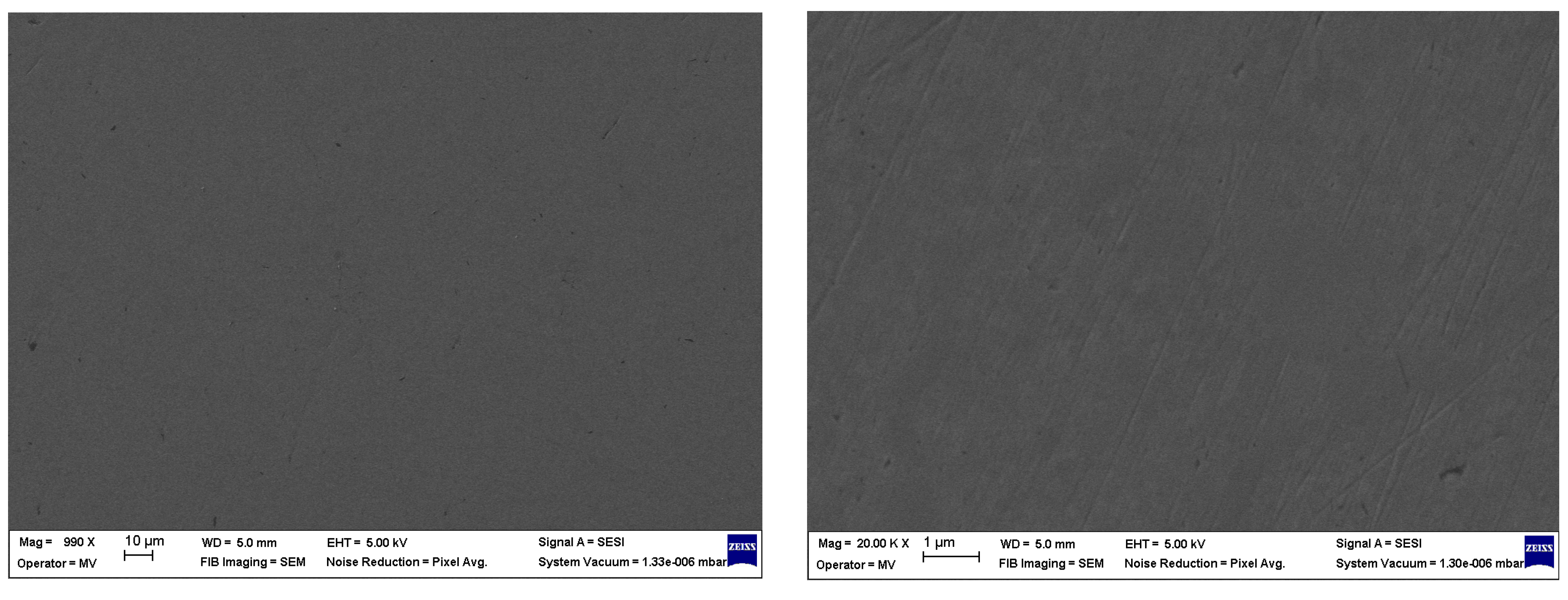
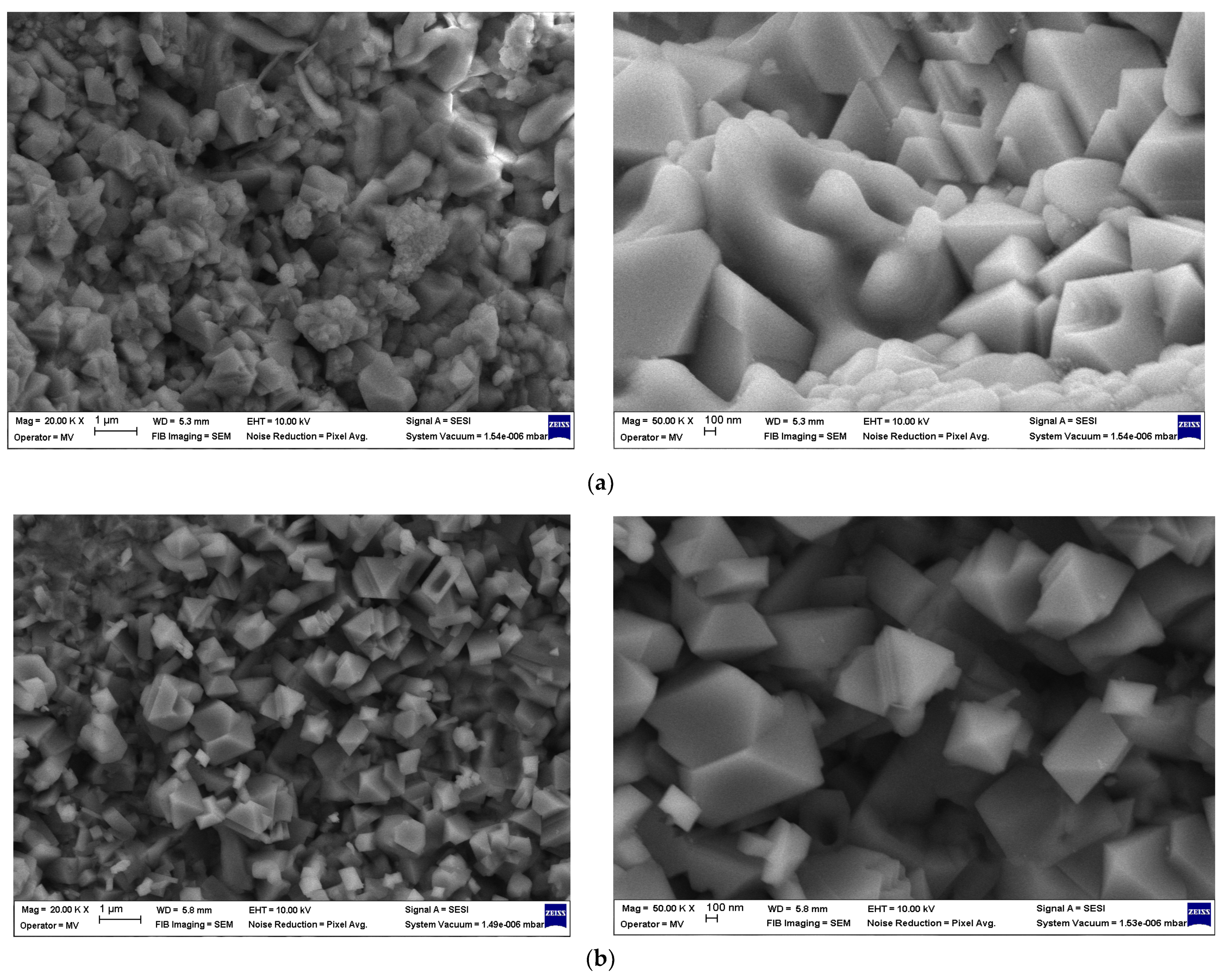
A low surface roughness (Ra of 0.21 ± 0.02 μm) and a columnar structure with pyramidal-shaped grains measuring several tenths of a nanometer were exhibited by the as-deposited SL and BL coatings, and no structural defects were observed by SEM analysis. A higher surface roughness (Ra of 2.45 ± 0.08 μm) and a coarser microstructure, characterized by a mix of pyramidal and prismatic grains, and some irregular grains ranging in size from a few hundred nanometers, were developed by the SL TT and BL TT coatings.
-
The presence of Ti, Al, Si, and N elements in all TiAlSiN-based coatings was confirmed by EDS analysis. However, oxygen contamination was also detected, indicated by the presence of the O element. Variations in elemental content were observed between the single-layer and bilayer coatings, as well as after thermal treatment.
-
Superior hardness was exhibited by the BL coating compared to the other coatings and the C120 tool steel substrate, as tested by nanoindentation. A slight decrease in hardness and elastic modulus was observed for the SL TT and BL TT coatings compared to the SL and BL coatings. Higher HIT/EIT and HIT/E* ratios were shown by all the coatings compared to the steel substrate, indicating better resistance to plastic deformation and improved wear resistance. The highest fracture toughness was observed in the BL TT coating (0.0354 GPa), which is 16.4 times greater than that of the steel substrate (0.0022 GPa).
-
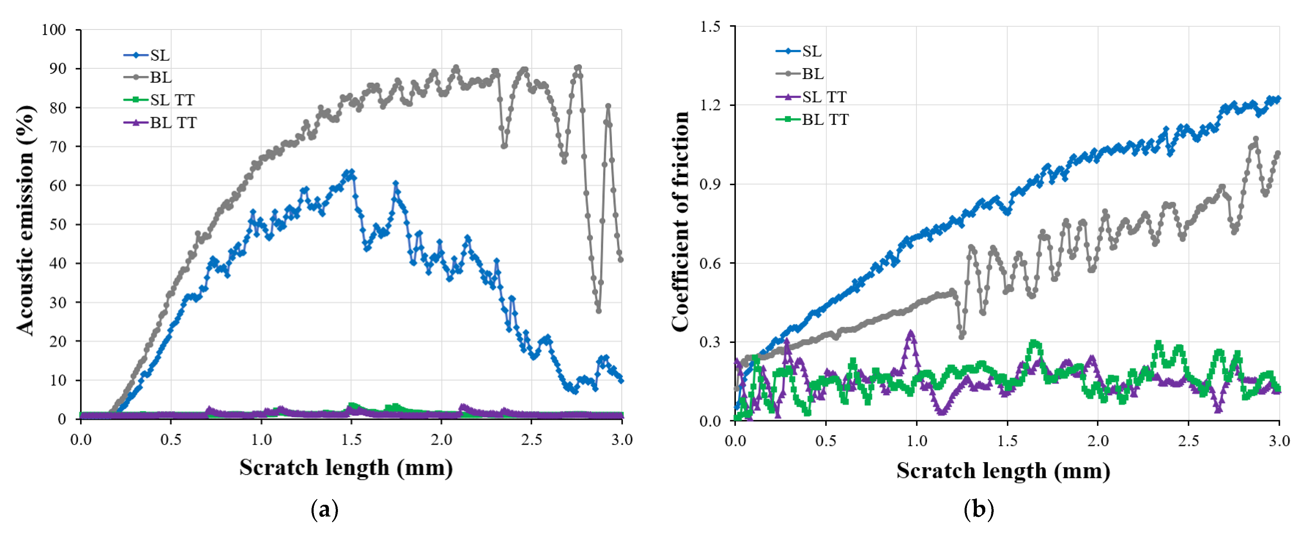
Both plastic and elastic behavior was exhibited by all TiAlSiN-based coatings, as indicated by the nanoindentation and micro-scratch results. Higher critical loads, improved adhesion, and better scratch resistance were demonstrated by both TT coatings compared to the SL and BL coatings. Stable behavior during scratching was shown by the SL TT and BL TT coatings, with very low AE values (≤3.3%) and a reduced COF (≤0.35), indicating that no exposure of the tool steel substrate occurred. The scratch performance of the BL and BL TT coatings was enhanced by the inclusion of the TiN mid layer.
-
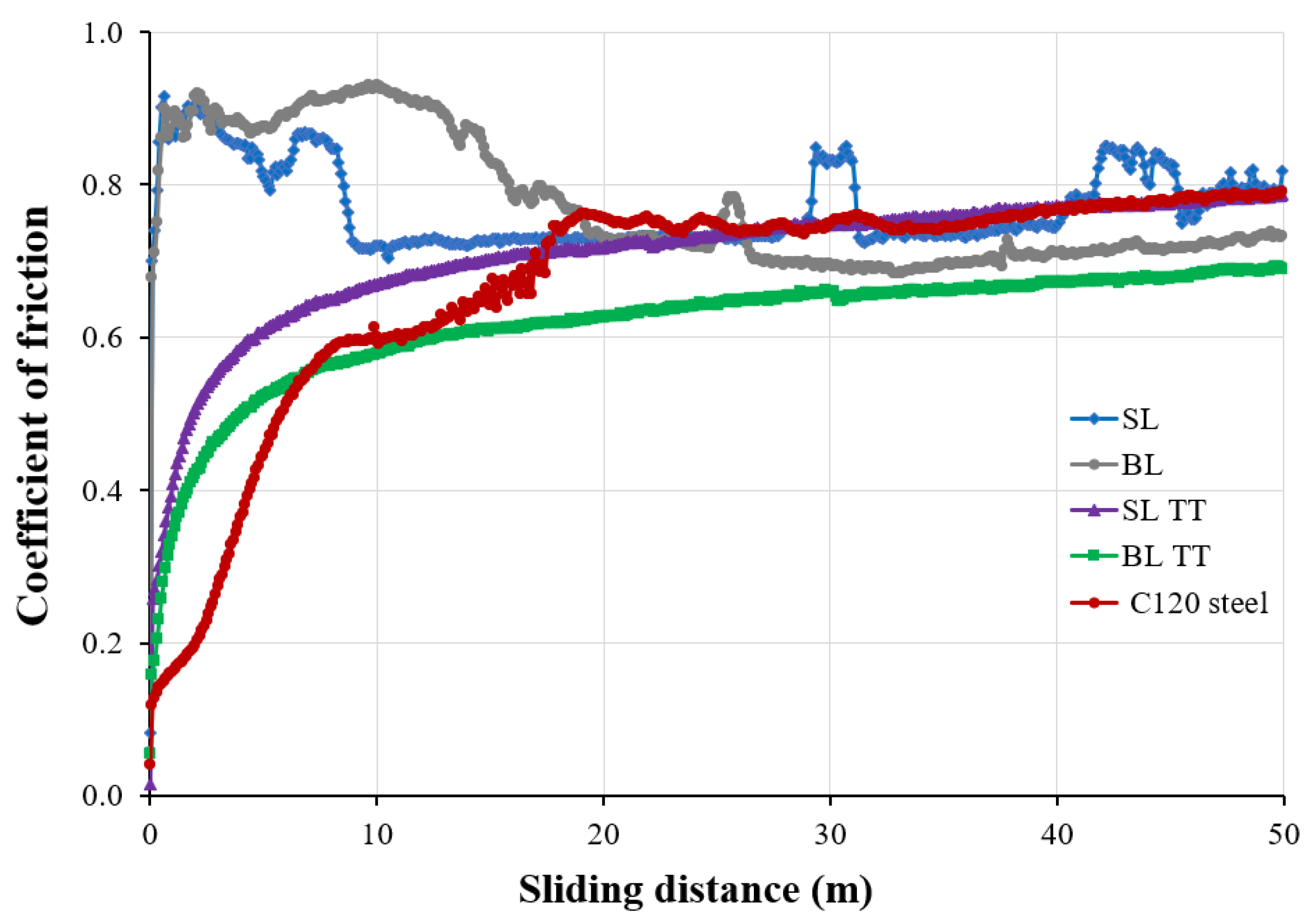
Higher Hertzian stress (contact pressure) and a lower wear rate were exhibited by the TiAlSiN coatings with higher elastic modulus (EIT) and indentation hardness (HIT). The lowest stable COF (0.58–0.69) over a sliding distance of 10–50 m was demonstrated by the BL TT coatings compared to the bare tool steel substrate and the other coatings.
-
The variation in COF and wear rate among the TiAlSiN-based coatings was attributed to changes in elemental content, microstructural features, and mechanical properties resulting from thermal treatment in air at 800 °C for 1 h.
-
Irreversible plastic deformation on the surface was shown by all samples subjected to tribological testing, caused by plowing due to wear particles and the hard asperities of the static partner (Al2O3 ball).
-
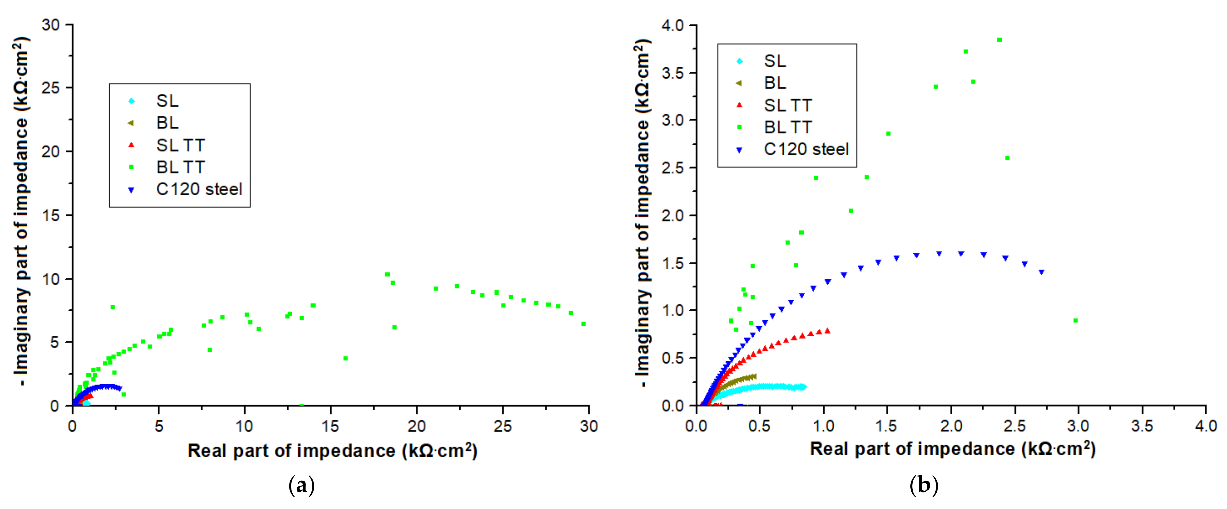
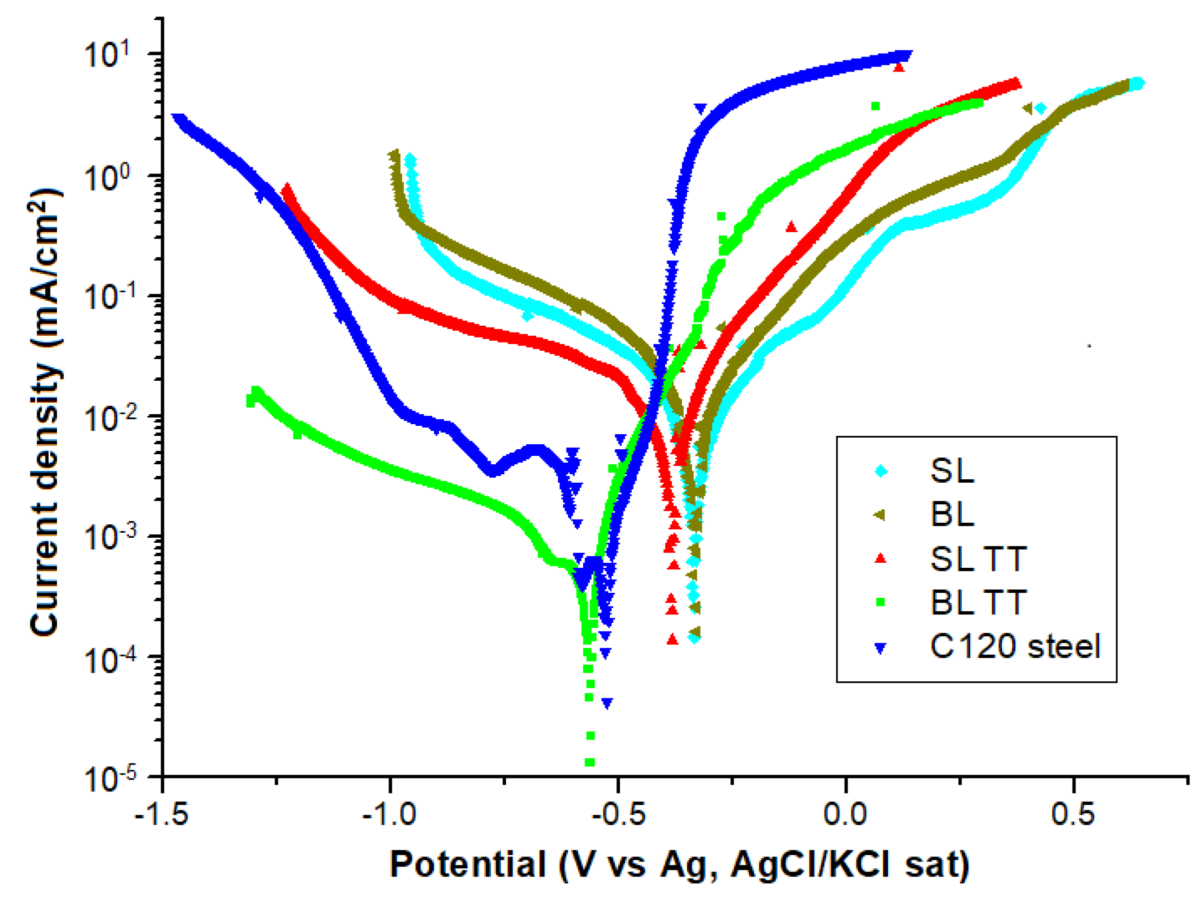
Effective protection against corrosion in a 3.5 wt.% NaCl solution was provided by the BL TT coating, as indicated by its lowest corrosion current density (0.1298 µA/cm2), highest polarization resistance (46.34 kΩ·cm2), and lowest corrosion rate (1.51 µm/year) among the tested TiAlSiN-based coatings and C120 tool steel substrate.
The potential of using magnetron sputtered TiAlSiN/TiN bilayer coatings as protective coatings for tool steel surfaces is showcased by this study, due to their superior mechanical, tribological, and electrochemical properties. The results are considered relevant for practical applications such as the coating of active contact surfaces on die tool steel components, including the inner diameters of dies and top surfaces of punches, which are subjected to frictional heating during pressing at high loads under dry sliding conditions. However, the deposition of TiAlSiN-based coatings on complex-shaped parts, the optimization of the chemical and mechanical properties of the coatings, and the evaluation of their performance in real operational environments are needed through further research.

5. Patents

The original solutions reported for sputtering targets were protected by Patent Application No. RO202000703A, filed on 05 November, 2020with the State Office for Inventions and Trademarks (OSIM), Bucharest, Romania, published as RO135723A2 on 30 May, 2022, and entitled “Metal Sputtering Targets Based on Titanium-Aluminium and Titanium-Silicon for Hard Wearproof Coatings and Process for Carrying Out the Same”, by authors M.V. Lungu, D. Tălpeanu, D. Pătroi, M. Lucaci, V. Tsakiris, and M. Marin.

Author Contributions

Conceptualization, M.V.L.; methodology, M.V.L. and D.T. (manufacture of sputtering targets and deposition of thin film coatings); validation and formal analysis, D.P. (mechanical investigation of sputtering targets, and preparation of steel substrate), V.M. (SEM and EDS analysis), M.V.L. (mechanical and tribological tests) and A.C. (electrochemical tests); resources, M.V.L.; data curation, M.V.L., D.T., A.C., D.P. and V.M.; writing—original draft preparation, M.V.L., R.C.C., A.C. and A.R.C.; writing—review and editing, M.V.L., R.C.C., A.C. and A.R.C.; visualization, M.V.L.; supervision, M.V.L.; project administration, M.V.L.; funding acquisition, M.V.L. All authors have read and agreed to the published version of the manuscript.

Funding

This research was funded by the Romanian Ministry of Research, Innovation, and Digitalization, project number PN 19310102, Contract numbers 46N/2019 and 42N/2023.

Institutional Review Board Statement

Not applicable.

Informed Consent Statement

Not applicable.

Data Availability Statement

The data presented in this study are available on request from the corresponding author.

Conflicts of Interest

The authors declare no conflicts of interest.

References

  1. Bobzin, K. High-Performance Coatings for Cutting Tools. CIRP J. Manuf. Sci. Tec. 2017, 18, 1–9. [Google Scholar] [CrossRef]
  2. Schulz, W.; Joukov, V.; Köhn, F.; Engelhart, W.; Schier, V.; Schubert, T.; Albrecht, J. The Behavior of TiAlN and TiAlCrSiN Films in Abrasive and Adhesive Tribological Contacts. Coatings 2023, 13, 1603. [Google Scholar] [CrossRef]
  3. Kolesnikov, V.I.; Novikov, E.S.; Kudryakov, O.V.; Varavka, V.N. The Degradation Mechanisms in Ion-Plasma Nanostructured Coatings under the Conditions of Contact Cyclic Loads. J. Phys. Conf. Ser. 2019, 1281, 012036. [Google Scholar] [CrossRef]
  4. Liu, J.; Wang, Y.; Liu, G.; Hua, J.; Deng, X. Properties and Performance of TiAlSiN and AlCrN Monolayer and Multilayer Coatings for Turning Ti-6Al-4V. Coatings 2023, 13, 1229. [Google Scholar] [CrossRef]
  5. Holmberg, K.; Laukkanen, A.; Turunen, E.; Laitinen, T. Wear Resistance Optimisation of Composite Coatings by Computational Microstructural Modelling. Surf. Coat. Technol. 2014, 247, 1–13. [Google Scholar] [CrossRef]
  6. Chang, K.; Dong, Y.; Zheng, G.; Jiang, X.; Yang, X.; Cheng, X.; Liu, H.; Zhao, G. Friction and Wear Properties of TiAlN Coated Tools with Different Levels of Surface Integrity. Ceram. Int. 2022, 48, 4433–4443. [Google Scholar] [CrossRef]
  7. Zhao, J.; Liu, Z.; Wang, B.; Song, Q.; Ren, X.; Wan, Y. Effects of Al Content in TiAlN Coatings on Tool Wear and Cutting Temperature during Dry Machining IN718. Tribol. Int. 2022, 171, 107540. [Google Scholar] [CrossRef]
  8. Dabees, S.; Mirzaei, S.; Kaspar, P.; Holcman, V.; Sobola, D. Characterization and Evaluation of Engineered Coating Techniques for Different Cutting Tools—Review. Materials 2022, 15, 5633. [Google Scholar] [CrossRef]
  9. Chen, H.; Zheng, B.C.; Ou, Y.X.; Lei, M.K. Microstructure and Thermal Conductivity of Ti-Al-Si-N Nanocomposite Coatings Deposited by Modulated Pulsed Power Magnetron Sputtering. Thin Solid Films 2020, 693, 137680. [Google Scholar] [CrossRef]
  10. Aljibori, H.S.; Alamiery, A.; Kadhum, A.A.H. Advances in Corrosion Protection Coatings: A Comprehensive Review. Int. J. Corros. Scale Inhib. 2023, 12, 1476–1520. [Google Scholar] [CrossRef]
  11. Liew, W.Y.H.; Lim, H.P.; Melvin, G.J.H.; Dayou, J.; Jiang, Z.-T. Thermal Stability, Mechanical Properties, and Tribological Performance of TiAlXN Coatings: Understanding the Effects of Alloying Additions. J. Mater. Res. Technol. 2022, 17, 961–1012. [Google Scholar] [CrossRef]
  12. Toboła, D.; Liskiewicz, T.; Yang, L.; Khan, T.; Boroń, Ł. Effect of Mechanical and Thermochemical Tool Steel Substrate Pre-Treatment on Diamond-like Carbon (DLC) Coating Durability. Surf. Coat. Technol. 2021, 422, 127483. [Google Scholar] [CrossRef]
  13. Bouzakis, K.-D.; Skordaris, G.; Gerardis, S.; Katirtzoglou, G.; Makrimallakis, S.; Pappa, M.; LilI, E.; M’Saoubi, R. Ambient and Elevated Temperature Properties of TiN, TiAlN and TiSiN PVD Films and Their Impact on the Cutting Performance of Coated Carbide Tools. Surf. Coat. Technol. 2009, 204, 1061–1065. [Google Scholar] [CrossRef]
  14. Gavrilov, N.V.; Kamenetskikh, A.S.; Chukin, A.V. Analysis of TiAlSiN Coatings Deposited by Reactive Magnetron Sputtering under High-Current Ion Assistance. J. Synch. Investig. 2017, 11, 671–676. [Google Scholar] [CrossRef]
  15. PalDey, S.; Deevi, S.C. Single Layer and Multilayer Wear Resistant Coatings of (Ti,Al)N: A Review. Mater. Sci. Eng. A 2003, 342, 58–79. [Google Scholar] [CrossRef]
  16. Shugurov, A.R.; Kazachenok, M.S. Mechanical Properties and Tribological Behavior of Magnetron Sputtered TiAlN/TiAl Multilayer Coatings. Surf. Coat. Technol. 2018, 353, 254–262. [Google Scholar] [CrossRef]
  17. Miletić, A.; Panjan, P.; Škorić, B.; Čekada, M.; Dražič, G.; Kovač, J. Microstructure and Mechanical Properties of Nanostructured Ti–Al–Si–N Coatings Deposited by Magnetron Sputtering. Surf. Coat. Technol. 2014, 241, 105–111. [Google Scholar] [CrossRef]
  18. Cao, F.; Munroe, P.; Zhou, Z.; Xie, Z. Mechanically Robust TiAlSiN Coatings Prepared by Pulsed-DC Magnetron Sputtering System: Scratch Response and Tribological Performance. Thin Solid Films 2018, 645, 222–230. [Google Scholar] [CrossRef]
  19. Liu, H.; Tang, J.-F.; Wang, X.; Li, W.; Chang, C.-L. Effects of Nitrogen-Argon Flow Ratio on the Microstructural and Mechanical Properties of TiAlSiN/CrN Multilayer Coatings Prepared Using High Power Impulse Magnetron Sputtering. J. Vac. Sci. Technol. A Vac. Surf. Films 2019, 37, 051501. [Google Scholar] [CrossRef]
  20. Zhou, Q.; Huang, B.; Zhang, E.; Peng, Z.; Chen, Q.; Liang, D. Improving the Mechanical and Tribological Properties of TiAlSiN Coatings by Annealing. Vacuum 2023, 214, 112249. [Google Scholar] [CrossRef]
  21. Sui, X.; Li, G.; Qin, X.; Yu, H.; Zhou, X.; Wang, K.; Wang, Q. Relationship of Microstructure, Mechanical Properties and Titanium Cutting Performance of TiAlN/TiAlSiN Composite Coated Tool. Ceram. Int. 2016, 42, 7524–7532. [Google Scholar] [CrossRef]
  22. Chen, J.K.; Chang, C.L.; Shieh, Y.N.; Tsai, K.J.; Tsai, B.H. Structures and Properties of (TiAlSi)N Films. Procedia Eng. 2012, 36, 335–340. [Google Scholar] [CrossRef]
  23. Kengesbekov, A.; Rakhadilov, B.; Sagdoldina, Z.; Buitkenov, D.; Dosymov, Y.; Kylyshkanov, M. Improving the Efficiency of Air Plasma Spraying of Titanium Nitride Powder. Coatings 2022, 12, 1644. [Google Scholar] [CrossRef]
  24. Heimann, R.B. The Nature of Plasma Spraying. Coatings 2023, 13, 622. [Google Scholar] [CrossRef]
  25. Lungu, M.V. An Insight into TiN, TiAlN and AlTiN Hard Coatings for Cutting Tools. Mat. Sci. Res. India 2020, 17, 87–89. [Google Scholar] [CrossRef]
  26. Bouzakis, K.-D.; Michailidis, N.; Skordaris, G.; Bouzakis, E.; Biermann, D.; M’Saoubi, R. Cutting with Coated Tools: Coating Technologies, Characterization Methods and Performance Optimization. CIRP Ann. 2012, 61, 703–723. [Google Scholar] [CrossRef]
  27. Lungu, M.V.; Enescu, E.; Tălpeanu, D.; Pătroi, D.; Marinescu, V.; Sobetkii, A.; Stancu, N.; Lucaci, M.; Marin, M.; Manta, E. Enhanced Metallic Targets Prepared by Spark Plasma Sintering for Sputtering Deposition of Protective Coatings. Mater. Res. Express 2019, 6, 076565. [Google Scholar] [CrossRef]
  28. Yoo, Y.H.; Le, D.P.; Kim, J.G.; Kim, S.K.; Vinh, P.V. Corrosion Behavior of TiN, TiAlN, TiAlSiN Thin Films Deposited on Tool Steel in the 3.5 Wt.% NaCl Solution. Thin Solid Film. 2008, 516, 3544–3548. [Google Scholar] [CrossRef]
  29. Yasin, J.; Selvakumar, S.; Mathan Kumar, P.; Sundaresan, R.; Arunraja, K.M. Experimental Study of TiN, TiAlN and TiSiN Coated High Speed Steel Tool. Mater. Today Proc. 2022, 64, 1707–1710. [Google Scholar] [CrossRef]
  30. Lü, W.; Li, G.; Zhou, Y.; Liu, S.; Wang, K.; Wang, Q. Effect of High Hardness and Adhesion of Gradient TiAlSiN Coating on Cutting Performance of Titanium Alloy. J. Alloys Compd. 2020, 820, 153137. [Google Scholar] [CrossRef]
  31. Ji, L.; Liu, H.; Huang, C.; Liu, X.; Chu, D.; Liu, Y.; Yao, P. Effect of Arc Deposition Process on Mechanical Properties and Microstructure of TiAlSiN Gradient Coatings. Ceram. Int. 2024, 50, 40014–40029. [Google Scholar] [CrossRef]
  32. Münz, W. Titanium Aluminum Nitride Films: A New Alternative to TiN Coatings. J. Vac. Sci. Technol. A Vac. Surf. Films 1986, 4, 2717–2725. [Google Scholar] [CrossRef]
  33. Fuentes, G.G.; Almandoz, E.; Pierrugues, R.; Martínez, R.; Rodríguez, R.J.; Caro, J.; Vilaseca, M. High Temperature Tribological Characterisation of TiAlSiN Coatings Produced by Cathodic Arc Evaporation. Surf. Coat. Technol. 2010, 205, 1368–1373. [Google Scholar] [CrossRef]
  34. He, N.; Li, H.; Ji, L.; Liu, X.; Zhou, H.; Chen, J. High Temperature Tribological Properties of TiAlSiN Coatings Produced by Hybrid PVD Technology. Tribol. Int. 2016, 98, 133–143. [Google Scholar] [CrossRef]
  35. Zhu, L.; Hu, M.; Ni, W.; Liu, Y. High Temperature Oxidation Behavior of Ti0.5Al0.5N Coating and Ti0.5Al0.4Si0.1N Coating. Vacuum 2012, 86, 1795–1799. [Google Scholar] [CrossRef]
  36. Rahman, M.M.; Jiang, Z.-T.; Zhou, Z.; Xie, Z.; Yin, C.Y.; Kabir, H.; Haque, M.M.; Amri, A.; Mondinos, N.; Altarawneh, M. Effects of Annealing Temperatures on the Morphological, Mechanical, Surface Chemical Bonding, and Solar Selectivity Properties of Sputtered TiAlSiN Thin Films. J. Alloys Compd. 2016, 671, 254–266. [Google Scholar] [CrossRef]
  37. Tillmann, W.; Fehr, A.; Stangier, D.; Dildrop, M. Influences of Substrate Pretreatments and Ti/Cr Interlayers on the Adhesion and Hardness of CrAlSiN and TiAlSiN Films Deposited on Al2O3 and ZrO2-8Y2O3 Thermal Barrier Coatings. Results Phys. 2019, 12, 2206–2212. [Google Scholar] [CrossRef]
  38. Philippon, D.; Godinho, V.; Nagy, P.M.; Delplancke-Ogletree, M.P.; Fernández, A. Endurance of TiAlSiN Coatings: Effect of Si and Bias on Wear and Adhesion. Wear 2011, 270, 541–549. [Google Scholar] [CrossRef]
  39. Sousa, V.F.C.; Silva, F.J.G.; Lopes, H.; Casais, R.C.B.; Baptista, A.; Pinto, G.; Alexandre, R. Wear Behavior and Machining Performance of TiAlSiN-Coated Tools Obtained by Dc MS and HiPIMS: A Comparative Study. Materials 2021, 14, 5122. [Google Scholar] [CrossRef]
  40. ISO 4957:2018; Tool Steels. ISO: Geneve, Switzerland, 2018.
  41. Lungu, M.V.; Tălpeanu, D.; Pătroi, D.; Lucaci, M.; Tsakiris, V.; Marin, M. Metal Sputtering Targets Based on Titanium-Aluminium and Titanium-Silicon for Hard WearProof Coatings and Process for Carrying Out the Same. RO135723A2, 30 May 2022. Available online: https://worldwide.espacenet.com/patent/search/family/081751063/publication/RO135723A2?q=pn%3DRO135723A2 (accessed on 9 September 2024).
  42. Oliver, W.C.; Pharr, G.M. An Improved Technique for Determining Hardness and Elastic Modulus Using Load and Displacement Sensing Indentation Experiments. J. Mater. Res. 1992, 7, 1564–1583. [Google Scholar] [CrossRef]
  43. ISO 14577-1:2015; Metallic Materials—Instrumented Indentation Test for Hardness and Materials Parameters, Part 1: Test Method. ISO: Geneve, Switzerland, 2015.
  44. ISO 14577-4:2016; Metallic Materials—Instrumented Indentation Test for Hardness and Materials Parameters, Part 4: Test Method for Metallic and Non-Metallic Coatings. ISO: Geneve, Switzerland, 2016.
  45. ASTM C1624-22; Test Method for Adhesion Strength and Mechanical Failure Modes of Ceramic Coatings by Quantitative Single Point Scratch Testing. ASTM: West Conshohocken, PA, USA, 2022. [CrossRef]
  46. ISO 20502:2005; Fine Ceramics (Advanced Ceramics, Advanced Technical Ceramics)—Determination of Adhesion of Ceramic Coatings by Scratch Testing. ISO: Geneve, Switzerland, 2005.
  47. Gil-Flores, L.; Salvador, M.D.; Penaranda-Foix, F.L.; Dalmau, A.; Fernández, A.; Borrell, A. Tribological and Wear Behaviour of Alumina Toughened Zirconia Nanocomposites Obtained by Pressureless Rapid Microwave Sintering. J. Mech. Behav. Biomed. Mater. 2020, 101, 103415. [Google Scholar] [CrossRef] [PubMed]
  48. Jana, A.; Dandapat, N.; Das, M.; Balla, V.K.; Chakraborty, S.; Saha, R.; Mallik, A.K. Severe Wear Behaviour of Alumina Balls Sliding against Diamond Ceramic Coatings. Bull. Mater. Sci. 2016, 39, 573–586. [Google Scholar] [CrossRef]
  49. ASTM G99-17; Test Method for Wear Testing with a Pin-on-Disk Apparatus. ASTM: West Conshohocken, PA, USA, 2023. [CrossRef]
  50. T-09-113—Wear and Friction Analysis of Thin Coatings. Available online: https://www.silcotek.com/hs-fs/hub/22765/file-341679011-pdf/docs/t-09-113_silcotek_tribology_testing_final_report.pdf (accessed on 4 July 2024).
  51. Kucharska, B.; Czarniak, P.; Kulikowski, K.; Krawczyńska, A.; Rożniatowski, K.; Kubacki, J.; Szymanowski, K.; Panjan, P.; Sobiecki, J.R. Comparison Study of PVD Coatings: TiN/AlTiN, TiN and TiAlSiN Used in Wood Machining. Materials 2022, 15, 7159. [Google Scholar] [CrossRef]
  52. Huang, B.; Chen, L.; Zhou, Q.; Zhang, E.; Li, C.; Wang, Y.; Liang, D.-D.; Chen, Q.; An, Q. Effects of Annealing Temperature on the Microstructure, Mechanical and Tribological Properties of TiAlSiCN Coatings. Ceram. Int. 2024, 50, 20612–20623. [Google Scholar] [CrossRef]
  53. Lekatou, A.G.; Emmanouilidou, S.; Dimitriadis, K.; Baikousi, M.; Karakassides, M.A.; Agathopoulos, S. Simulating Porcelain Firing Effect on the Structure, Corrosion and Mechanical Properties of Co–Cr–Mo Dental Alloy Fabricated by Soft Milling. Odontology 2023, 112, 372–389. [Google Scholar] [CrossRef]
  54. Das, S.; Guha, S.; Ghadai, R.; Swain, B.P. A Comparative Analysis over Different Properties of TiN, TiAlN and TiAlSiN Thin Film Coatings Grown in Nitrogen Gas Atmosphere. Mat. Chem. Phys. 2021, 258, 123866. [Google Scholar] [CrossRef]
  55. Weikert, T.; Wartzack, S.; Baloglu, M.V.; Willner, K.; Gabel, S.; Merle, B.; Pineda, F.; Walczak, M.; Marian, M.; Rosenkranz, A.; et al. Evaluation of the Surface Fatigue Behavior of Amorphous Carbon Coatings through Cyclic Nanoindentation. Surf. Coat. Technol. 2021, 407, 126769. [Google Scholar] [CrossRef]
  56. He, C.; Zhang, J.; Song, G.; Ma, G.; Du, Z.; Wang, J.; Zhao, D. Microstructure and Mechanical Properties of Reactive Sputtered Nanocrystalline (Ti,Al)N Films. Thin Solid Films 2015, 584, 192–197. [Google Scholar] [CrossRef]
  57. Lungu, M.V.; Sobetkii, A.; Sobetkii, A.A.; Pătroi, D.; Prioteasa, P.; Ion, I.; Negrilă, C.C.; Chifiriuc, M.C. Functional Properties Improvement of Ag-ZnO Thin Films Using Inconel 600 Interlayer Produced by Electron Beam Evaporation Technique. Thin Solid Films 2018, 667, 76–87. [Google Scholar] [CrossRef]
  58. Li, B.; Xu, Y.; Rao, G.; Wang, Q.; Zheng, J.; Zhu, R.; Chen, Y. Tribological Properties and Cutting Performance of AlTiN Coatings with Various Geometric Structures. Coatings 2023, 13, 402. [Google Scholar] [CrossRef]
  59. Zmitrowicz, A. Wear Patterns and Laws of Wear—A Review. J. Theor. Appl. Mech. 2006, 44, 219–253. [Google Scholar]
  60. Das, C.R.; Rangwala, M.; Ghosh, A. Effect of Si Contents on Microstructure and Mechanical Characteristics of TiAlSiN Thin Film Deposited by HiPIMS Using Different Ti Si Target Compositions. Surf. Coat. Technol. 2024, 476, 130212. [Google Scholar] [CrossRef]
  61. Ou, Y.X.; Chen, H.; Li, Z.Y.; Lin, J.; Pan, W.; Lei, M.K. Microstructure and Tribological Behavior of TiAlSiN Coatings Deposited by Deep Oscillation Magnetron Sputtering. J. Am. Ceram. Soc. 2018, 101, 5166–5176. [Google Scholar] [CrossRef]
  62. Komartin, R.S.; Balanuca, B.; Necolau, M.I.; Cojocaru, A.; Stan, R. Composite Materials from Renewable Resources as Sustainable Corrosion Protection Coatings. Polymers 2021, 13, 3792. [Google Scholar] [CrossRef]
  63. Li, R.T.; Murugan, V.K.; Dong, Z.L.; Khor, K.A. Comparative Study on the Corrosion Resistance of Al–Cr–Fe Alloy Containing Quasicrystals and Pure Al. J. Mater. Sci. Technol. 2016, 32, 1054–1058. [Google Scholar] [CrossRef]
  64. ASTM G59-97(2020); Test Method for Conducting Potentiodynamic Polarization Resistance Measurements. ASTM: West Conshohocken, PA, USA, 2020. [CrossRef]
  65. Shao, J. The Effect of Sealing Processes on the Corrosion Behaviour of Al₂O₃-13 wt.%TiO₂ Coating. Ceramics-Silikaty 2019, 63, 185–193. [Google Scholar] [CrossRef]
Figure 1. Macrographic aspect of (a) TiAlSi 75–20–5 at.%, and (b) Ti sputtering targets.
Coatings 14 01184 g001
Figure 2. Illustration of the equipment used in the deposition process.
Coatings 14 01184 g002
Figure 3. Illustration of the equipment used in the investigation of the samples.
Coatings 14 01184 g003
Figure 4. Macrographic aspect of (a) SL and (b) BL coatings deposited on C120 tool steel substrate.
Coatings 14 01184 g004
Figure 5. SEM images (left image 990×, and right image 20,000×) of the polished C120 steel substrate.
Coatings 14 01184 g005
Figure 6. SEM images using InLens detector (left image at 100,000× and right image at 200,000×) of the top surface for (a) TiAlSiN (SL), (b) TiAlSiN/TiN (BL), and (c) TiN thin film coatings.
Coatings 14 01184 g006
Figure 7. SEM images using SESI detector (left image 20,000×, and right image 50,000×) of the top surface for (a) SL TT and (b) BL TT thin film coatings.
Coatings 14 01184 g007
Figure 8. Load–displacement curves for (a) TiAlSiN-based coatings and (b) C120 steel substrate.
Coatings 14 01184 g008
Figure 9. Variation in (a) penetration depth (Pd) and residual depth (Rd), and (b) elastic recovery (ER) for the TiAlSiN-based coatings tested over a 3 mm scratch length.
Coatings 14 01184 g009
Figure 10. Variation in (a) acoustic emission, and (b) coefficient of friction for the TiAlSiN-based coatings tested over a 3 mm scratch length.
Coatings 14 01184 g010
Figure 11. Optical images (20× magnification) of the scratch tracks left on (a) SL, (b), BL, (c) SL TT, and (d) BL TT coatings tested over a 3 mm scratch length with a linear progressive normal load from 0.03 N to 30 N.
Coatings 14 01184 g011
Figure 12. Optical images (20× magnification) showing the width (ΔY) of the wear track at the end of the 3 mm scratch length for (a) SL, (b), BL, (c) SL TT, and (d) BL TT coatings tested with a linear progressive normal load from 0.03 N to 30 N.
Coatings 14 01184 g012aCoatings 14 01184 g012b
Figure 13. Evolution of coefficient of friction with sliding distance for the TiAlSiN-based coatings and C120 steel substrate recorded during the tribological tests.
Coatings 14 01184 g013
Figure 14. Open circuit potential (EOC) variation with immersion time in a 3.5 wt.% NaCl solution for the TiAlSiN-based coatings and C120 steel substrate.
Coatings 14 01184 g014
Figure 15. Nyquist plots of impedance on the Ox/Oy scale: (a) 0–30 kΩ·cm2 and (b) 0–4 kΩ·cm2 for the samples after 20 min of immersion in a 3.5 wt.% NaCl solution.
Coatings 14 01184 g015
Figure 16. PDP curves showing the corrosion behavior of the samples in a 3.5 wt.% NaCl solution.
Coatings 14 01184 g016
Table 1. Main characteristics of the sputtering targets obtained using the SPS process [27,41].
Technical CharacteristicsTiAlSi 75–20–5 (at.%) TargetTi Target
Diameter × thickness (mm × mm)50.8 × 6.350.8 × 6.3
Density (g/cm3)4.093 ± 0.0034.379 ± 0.001
Surface roughness Ra (µm)≤0.2≤0.2
Thermal conductivity at 25 °C (W.m−1.K−1)11.93 ± 0.1318.38 ± 0.14
Indentation hardness, HIT (GPa)7.88 ± 0.642.77 ± 0.08
Vickers hardness HV0.02/10730 ± 59256 ± 7
Elastic modulus, EIT (GPa)163 ± 6117 ± 6
Table 2. Deposition conditions used in the DC magnetron sputtering process.
Deposition ConditionsTiAlSiN FilmsTiN Films
Sputtering target typeTiAlSi 75–20–5 (at.%)Ti
Substrate rotation speed (rpm)1010
Substrate temperature (°C)300300
Heating rate of the substrate (°C/min)3030
Ar + N2 gas flow (sccm)15 + 715 + 7
Start vacuum pressure (mbar)10−610−6
Working vacuum pressure (mbar)(1.5–2) × 10−2(1.5–2) × 10−2
Initial power (W)5050
Deposition power (W)200200
Deposition rate (Å/s)0.32 ± 0.060.12 ± 0.03
Film thickness (nm)800100
Table 3. Measurement conditions for determining the mechanical properties of the TiAlSiN-based coatings and C120 steel substrate using nanoindentation and the Oliver and Pharr method.
Measurement Conditions in
Instrumented Nanoindentation Testing
TiAlSiN-Based CoatingsC120 Steel
Substrate
Maximum indentation load (Fmax) (mN)2.5 ± 0.1300 ± 1
Loading typelinearlinear
Indenter approach speed to the sample (nm/min)10002000
Loading/unloading rate (nm/min)500600
Pause at Fmax (s)00
Data acquisition frequency (Hz)1010
Poisson’s ratio (ν)0.250.30
Table 4. Elemental content of the TiAlSiN-based coatings determined using EDS analysis.
SampleElemental Content ± SD (wt.%)
TiAlSiNOFeCrMn
SL52.4 ± 0.311.9 ± 0.13.0 ± 0.121.2 ± 0.311.5 ± 0.3---
BL51.7 ± 0.312.1 ± 0.13.6 ± 0.121.4 ± 0.311.2 ± 0.3---
TiN56.6 ± 0.4--5.3 ± 0.231.1 ± 0.34.5 ± 0.42.5 ± 0.2-
SL TT26.7 ± 0.14.8 ± 0.10.5 ± 0.1-27.4 ± 0.138.0 ± 0.10.8 ± 0.11.8 ± 0.1
BL TT23.4 ± 0.17.7 ± 0.11.1 ± 0.1-29.7 ± 0.134.0 ± 0.10.4 ± 0.13.7 ± 0.1
Table 5. Mechanical properties of the TiAlSiN-based coatings and C120 tool steel substrate.
SampleHIT
(GPa)
HVEIT
(GPa)
E*
(GPa)
HIT/EITHIT/E*HIT3/EIT2
(GPa)
HIT3/E*2
(GPa)
Welast
(pJ)
Wplast
(pJ)
ηIT
(%)
SL10.29 ± 0.26953 ± 24216 ± 15231 ±170.04760.04450.02340.020412.59 ± 1.1734.62 ± 2.0326.64 ± 0.67
BL10.45 ± 0.32968 ± 29215 ± 16229 ± 180.04860.04560.02470.021814.25 ± 0.4336.15 ± 1.5828.28 ± 0.27
SL TT9.98 ± 0.18925 ± 16188 ± 5201 ± 50.05310.04970.02810.024611.74 ± 0.0331.89 ± 1.8426.93 ± 1.08
BL TT9.19 ± 0.09851 ± 8139 ± 5148 ± 60.06610.06210.04020.035411.12 ± 3.1934.83 ± 1.2424.08 ± 5.93
C120 steel4.45 ± 0.09412 ± 8184 ± 2202 ± 20.02420.02200.00260.002229,335.52 ± 366.46176,769.48 ± 8580.5314.25 ± 0.43
Table 6. Critical loads for the TiAlSiN-based coatings deposited on C120 tool steel substrate.
SampleOptical Critical LoadsPd Critical Load (N)AE Critical Load (N)
Lc1 (N)Lc2 (N)Lc3 (N)
SL2.656.3114.03-14.38
BL3.2812.2617.28-20.52
SL TT3.8913.63-12.5015.02
BL TT4.7227.82-16.4121.21
Table 7. Coefficient of friction (µ) and specific wear rate (Ws) for the TiAlSiN-based coatings and C120 steel substrate samples.
SampleCoefficient of Friction (µ)Worn Track Area
(µm²)
Specific Wear Rate (mm³/N·m)
µminimumµmaximumµmean ± SD
SL0.0830.9160.770 ± 0.053946.2–1062.4(2.14–2.40) × 10−4
BL0.0560.9310.773 ± 0.084866.8–986.7(1.96–2.23) × 10−4
SL TT0.0150.7890.708 ± 0.0881291.3–1891.9(2.92–4.28) × 10−4
BL TT0.0550.6940.616 ± 0.0831237.2–1683.1(2.80–3.80) × 10−4
C120 steel0.0410.8220.670± 0.1621173.8–1646.4(2.65–3.72) × 10−4
Table 8. Electrochemical parameters obtained from EIS measurements before the PDP test of the samples in the 3.5 wt.% NaCl solution after 20 min of immersion.
SampleR1
(Ω cm2)
R2
(Ω cm2)
Cdl
(µF/cm²)
SL47.341057150.4
BL66.03854.51862.0
SL TT66.032184728.7
BL TT147.135,5500.159
C120 steel68.354182240.4
Table 9. Electrochemical corrosion parameters derived from the PDP curves for the samples in a 3.5 wt.% NaCl solution.
SampleEcorr
(mV vs Ag, AgCl/KCl)
icorr
(µA/cm²)
Rp
(kΩ cm2)
βa
(mV/dec)
βc
(mV/dec)
CR
(µm/year)
SL−340.91.13935.0733.9−34.613.24
BL−338.91.25673.9226.8−31.414.60
SL TT−384.31.16583.064.2−41.513.55
BL TT−567.70.129846.3425.7−45.21.51
C120 steel−532.50.182528.5222.4−36.22.12
Disclaimer/Publisher’s Note: The statements, opinions and data contained in all publications are solely those of the individual author(s) and contributor(s) and not of MDPI and/or the editor(s). MDPI and/or the editor(s) disclaim responsibility for any injury to people or property resulting from any ideas, methods, instructions or products referred to in the content.

