Article

Structural Design and Mechanical Properties Analysis of Laminated SiAlON Ceramic Tool Materials

1
School of Mechanical Engineering, Qilu University of Technology (Shandong Academy of Sciences), Jinan 250353, China
2
Key Laboratory of Equipments Manufacturing and Intelligent Measurement and Control, China National Light Industry, Qilu University of Technology (Shandong Academy of Sciences), Jinan 250353, China
3
Shandong Institute of Mechanical Design and Research, Jinan 250031, China
4
Dezhou United Petroleum Technology Corp., Jinan 253034, China
*
Author to whom correspondence should be addressed.
Coatings 2024, 14(9), 1218; https://doi.org/10.3390/coatings14091218
Submission received: 21 August 2024 / Revised: 13 September 2024 / Accepted: 18 September 2024 / Published: 21 September 2024

Abstract

:
Based on finite element simulation analysis, laminated ceramic tool materials with different structures were designed and the effect of laminated structure on tool state was investigated. Residual stresses in ceramic tool materials increase with the number of layers and layer–thickness ratio. Based on the simulation results, SiAlON-SiC-SiCw/SiAlON-Al2O3 ceramic tool materials (SCWAs) were prepared using the spark plasma sintering process, and the influence of residual stress on the mechanical properties and microstructure of laminated ceramic tool materials was studied. The mechanical properties of ceramic materials were significantly improved under the effect of residual stresses. The fracture toughness of SCWA4 with 7 layers and a layer–thickness ratio of 6 was 6.02 ± 0.19 MPa·m1/2, and the front and side flexural strengths were 602 ± 19 MPa and 595 ± 17 MPa, 36.3% and 39.0% higher than homogeneous SiAlON ceramics, respectively.

1. Introduction

In recent years, the application of ceramic cutting tools has made great progress. Compared to traditional cemented carbide, high-speed steel and other cutting tool materials, ceramic cutting tools show excellent performance, with properties such as good wear, heat resistance and strong chemical stability. However, brittleness is still a significant defect of ceramic cutting tools, greatly limiting their development and application [1]. In order to improve the toughness of ceramic tool materials, scientists have developed laminated ceramic tool materials [2,3]. Based on the composite structure, a soft layer is inserted in the middle of a harder ceramic. Excess energy can be fully absorbed to enhance the mechanical properties of the material, thus achieving the effect of toughening and strengthening. This is the basic principle of laminated ceramic tools.
Differences in the coefficients of thermal expansion of the raw materials and differences in average particle size of the different layers are particularly important for the mechanical properties of laminated ceramic materials. A larger layer number and thickness ratio can increase the residual stress between layers [4]. Hadraba [5] developed Al2O3/ZrO2/BaTiO3-stacked ceramic cutting tool materials. Their results showed that residual stresses are effective in improving fracture toughness. Li [6] prepared laminated ZrB2-SiC/SiCw ceramic materials. Fracture toughness was substantially improved to 14.5 MPa·m1/2. Liu [7] prepared laminated Al2O3-ZrB2-MgO/Al2O3-TiN-MgO (AZTM) ceramic composites. Their fracture toughnesses were significantly improved compared to normal Al2O3-TiN ceramic tool materials. Micro and macro crack deflection and crack bifurcation favored fracture toughness improvement. Cracks change their propagation direction when they encounter interlayer interfaces, resulting in crack deflection and consumption of the energy required for crack propagation. The energy dissipation mechanism enables laminated ceramic materials to have better toughness than ordinary ceramic materials [8]. The multi-scale deformation of cracks along the interface layer and the residual stress in the materials significantly help to improve fracture toughness. Adding some special components to the intermediate layer and surface layer can achieve different reinforcement effects. Wang et al. [9] improved flexural strength by adding ZrB2 particles to the intermediate layer. Cui et al. [10] significantly reduced the friction coefficient and improved the wear resistance of laminated ceramic tools by adding graphene. Chen [11] designed a laminated ceramic cutting tool based on a finite element model. Through the dual effect of graphene and residual compressive stress on the surface, crack deflection, crack bifurcation and bridging toughening were generated. The fracture mode changed from transgranular fracture to a combination of intergranular fracture and transgranular fracture, enhancing the mechanical properties of the tool.
SiAlON ceramics have better sintering properties than Si3N4 ceramics, providing more possibilities for the development of Si3N4 materials [12]. Adding a reinforcement phase can improve one or more properties while maintaining other excellent properties. Liu [13] prepared a novel Al2O3 ceramic tool material. The mechanical properties of Al2O3 ceramic tools were greatly improved by toughening with SiC whiskers and nanoparticles. Sun [14] prepared nanolaminated WC/ZrO2/Al2O3/GNPs ceramic materials. It was found that graphene could not only improve breaking toughness, but its synergistic effect with the laminated structure was also an important reason for enhancing its mechanical properties. The addition of SiC [15] and SiC whiskers [16] can both enhance the mechanical properties of ceramic materials and help to improve the densification of some ceramic materials. Dong [17] investigated the role of different sizes of SiC particles on Al2O3 ceramic materials. It was found that Al2O3/SiC ceramic materials display a trans-lattice fracture phenomenon. The addition of large SiC particles optimized its Vickers hardness remarkably. This was mainly due to the occurrence of crack deflection. Khan [18] prepared α-SiAlON/SiC ceramic materials. Their mechanical properties were found to be substantially improved compared to those of homogeneous α-SiAlON. This was mainly due to crack deflection, crack bridging and grain pullout induced by SiC particles. In preceding studies, we studied the effect of SiC and SiC whiskers on the mechanical properties of SiAlON ceramics. The addition of SiC can appropriately improve the Vickers hardness of ceramic materials. The addition of SiC whiskers can appropriately enhance fracture toughness but reduces Vickers hardness. The mechanical properties of SiAlON/SiC/SiCw ceramic materials were optimized when 20% SiC and 10% SiC whiskers were added.
Finite element analysis is a powerful numerical computing technique. It divides complex structures into small, simple units and applies mathematical models to simulate their behaviors and performances under different loads [19,20,21]. The method is widely used in engineering design to predict various physical phenomena such as structural strength, deformation and temperature distribution. This optimizes product design, reduces costs and ensures safety and reliability. Wang [22] established a model to analyze the self-healing behavior of ceramic materials. The model could not only describe the isotropic damage process under specific boundary conditions, but could also describe the self-healing process under high temperatures. Zhang [23] studied the effect of TiC on residual stresses in AMB ceramic substrates. It was found that, due to the high hardness of TiC, most of the stress concentration occurred around the TiC particles.
In this study, a finite element model of a laminated SiAlON ceramic cutting tool material was developed to investigate the effect of a laminated structure on its residual stress. Then, laminated SiAlON ceramic cutting tool materials were experimentally prepared to investigate the role of residual stress. The toughening mechanism of the laminated SiAlON ceramic tool materials was also analyzed.

2. Experimental Materials and Methods

2.1. Generation of Residual Stress

Different ceramic materials have different coefficients of thermal expansion, and their deformation and stress are different when the temperature changes. For a three-layer ceramic material, the coefficient of thermal expansion of the surface ceramic material is small, while that of the matrix ceramic material is large [24]. When cooling from a high temperature to a normal temperature, each layer of the material will shrink to different degrees during the cooling process. However, in laminated ceramic materials, the layers are bound to each other. As a result, the stress generated during cooling cannot be released, resulting in residual stress [25]. The surface layer with a low thermal expansion coefficient produces residual compressive stress, while the matrix layer produces residual tensile stress.

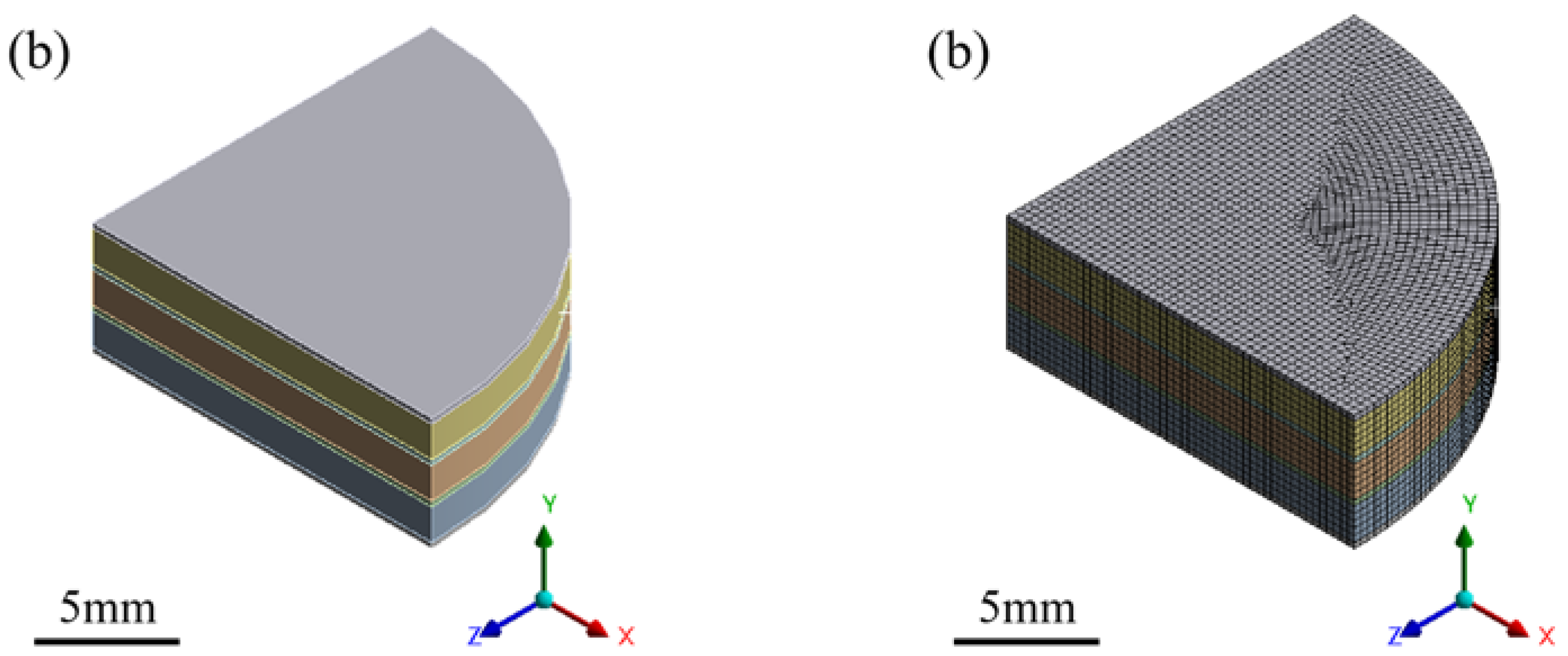
2.2. Finite Element Model

In this study, SiAlON/SiC/SiCw (SCW, where SiAlON is silicon aluminum oxynitride and SiCw is the SiC whisker) was selected as the surface layer, and SiAlON/Al2O3 (SA) was selected as the matrix layer. The SCW and SA layers were combined in alternating stacks. Table 1 shows the purities, average particle sizes and source of the powders used in this investigation. The detailed components of the SCW layer and SA layer materials are shown in Table 2. Figure 1 shows a structure diagram of the laminated SiAlON ceramic materials (SCWAs) when the number of layers is 5 and the layer thickness ratio is 6.
Table 3 lists the physical property parameters of various kinds of raw materials. Assuming that these materials are homogeneous and isotropic linear elastic materials, the parameters of various kinds of ceramic components can be calculated using the mixing rule [11,26]. For the binary composite consisting of two components (denoted as material A and material B), if the volume fraction of material B is f B , the formula for calculating the parameters of the binary composite is as follows:
Thermal expansion
α * = α A + f B α B α A 12 K A G A 3 K A + 4 G A f B K A + 1 4 G A + 1 f B 3 K B
Thermal conductivity
λ * = λ A 1 + 2 f B 1 λ A λ B 1 + 2 λ A λ B 1 f B 1 λ A λ B 1 + λ A λ B
Elastic modulus
E * = 9 K * G * 3 K * + G *
Poisson’s ratio
v * = 3 K * 2 G * 2 3 K * + G *
Equivalent bulk modulus
K * = K A 1 + f B K B K A K A + a 1 f B K B K A
Equivalent shear modulus
G * = G A 1 + f B G B G A G A + a 1 f B G B G A
where K A = E A 3 ( 1 2 ν A ) , K B = E B 3 ( 1 2 ν B ) , G A = E A 2 ( 1 + ν A ) , G B = E B 2 ( 1 + ν B ) , a = 1 3 1 + ν A 1 ν A , b = 2 15 4 5 ν A 1 ν A . f B is the volume content of material B, α is the coefficient of thermal expansion, λ is the thermal conductivity, E is the modulus of elasticity, ν is the Poisson’s ratio, K * is the equivalent bulk modulus, G * is the equivalent shear modulus, K is the bulk modulus, G is the shear modulus, ν A and ν B are the Poisson’s ratios of material a and the material b, respectively, and a and b are the factors.
For ternary composite materials, a separate calculation method can be used. First, the physical property parameters of any two components in the material can be calculated using the above formula. Then, the two components are regarded as a new whole material A. The remaining third phase material is regarded as material B. Finally, the calculations are performed using the above equation. Table 4 shows the physical property parameters of the SCW layer and SA layer.
In order to avoid the coupling of stresses [27], laminated ceramic materials are designed in a symmetrical structure. The main objective of this study is to determine how the number of layers (n) and the layer thickness ratio (D) affect the residual stress distribution in SCWAs. In this study, the total layer thickness of the tool was set as 5 mm and the diameter as 30 mm. Table 5 shows the corresponding relationship between the finite element model of SCWAs and different laminated constructions, where the layer thickness ratio refers to the proportional relationship between the thickness of the SA layer and the SCW layer; that is, D = h2/h1.
The residual stresses generated when the laminated SiAlON ceramic was cooled from its sintering temperature (1700 °C) to room temperature (25 °C) were simulated using ANSYS 2020R2 software for the efficient calculation of residual stresses. Based on the axisymmetric structure and temperature loads shown in Figure 1, the 1/4 model shown in Figure 2 was built and meshed. Figure 3 shows a flow chart of the finite element analysis. In order to benefit from the calculations using the ANSYS software, we assumed that some physical properties of the SA and SCW are as follows: (a) their physical parameters maintain constant values and are isotropic; (b) their heat transfers during cooling are convective heat transfer; and (c) their layers are flat and homogeneous, and they undergo only elastic deformation.

2.3. Experimental Procedure

The powder of each raw material was added to anhydrous ethanol solution with polyethylene glycol (PEG) separately and dispersed by ultrasonication, where the ultrasonication time was 5 min and the content of PEG was 1%–2% of the mass of the ceramic powder. The fully dispersed solution of each powder was mixed and further ultrasonicated for 0.5 h to ensure that the various components of the mixture were uniformly dispersed. The dispersed solution and Al2O3 ceramic balls (where the balls/powder ratio is 3/1 and ball diameter is 6 mm) were placed in a ball milling tank and nitrogen was added. The jars were then placed in ball-milling equipment and ball-milled continuously for 48 h. After drying, the dried powder was sieved through a 100-mesh sieve to obtain the ceramic powder. The ceramic material powder was alternately pressed into the graphite mold. After all the powder was placed into the mold, it was then placed into the Japanese SPS-625HF spark plasma sintering furnace for sintering. The sintering temperature was 1700 °C, the sintering pressure was 30 MPa, and the holding time was 10 min. The heating rate was 100 °C/min up to 1350 °C, and 50 °C/min between 1350 °C and 1700 °C. After sintering was completed, the sintered samples were naturally cooled to room temperature. The mechanical properties were tested and the microstructures analyzed.

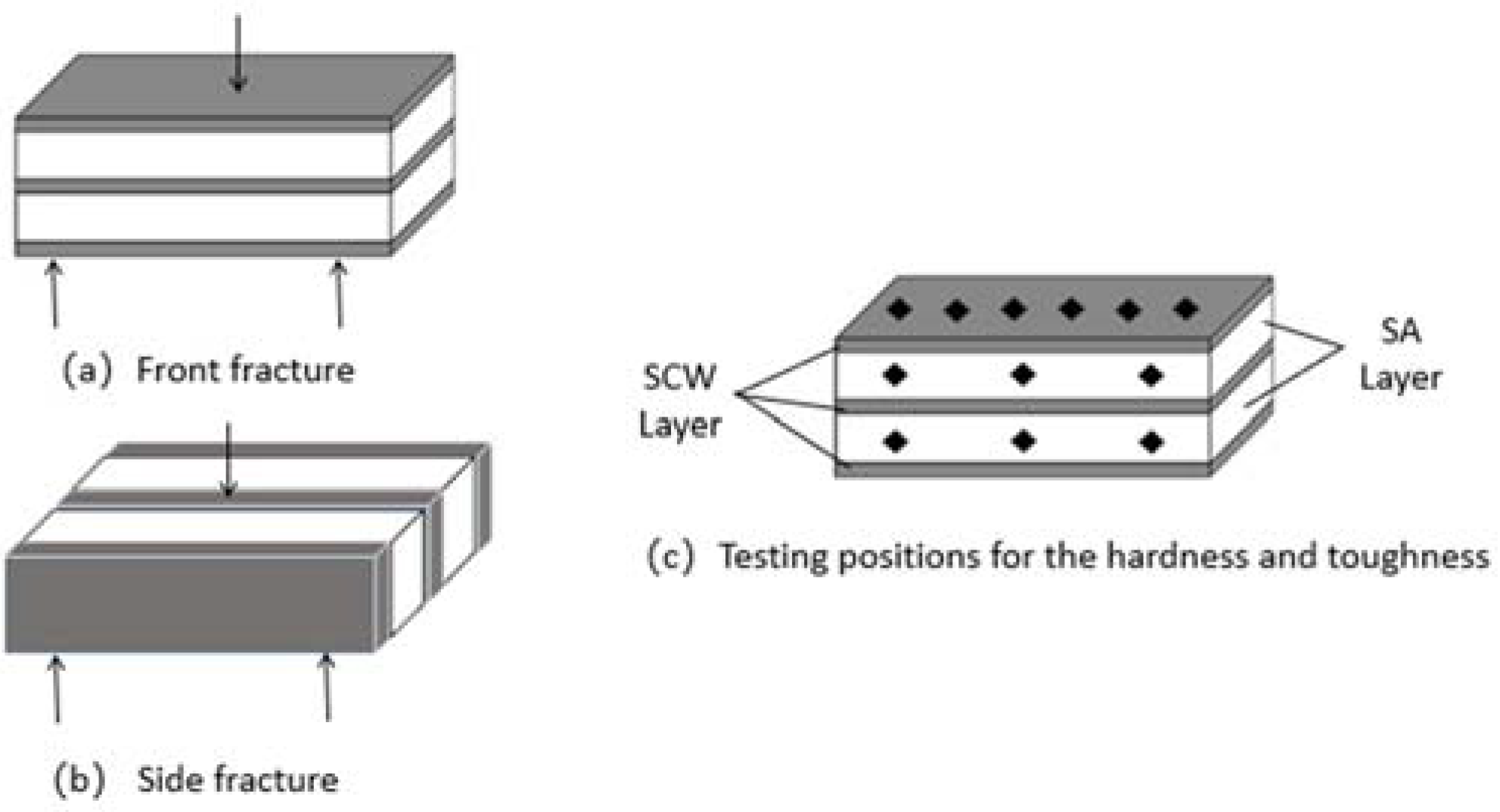
2.4. Characterization

Because the flexural strengths of SCWAs are anisotropic, they should be measured in two different directions. After sintering, the ceramic materials were machined into a strip shape of 3 mm × 4 mm × 25 mm to characterize their mechanical properties. The test method of mechanical properties is shown in Figure 4.
The flexural strength of ceramic tool materials was measured using the three-point bending method, and the experimental apparatus used was an electronic universal testing machine (AGS-X5KN, SHIMADZU, Kyoto, Japan). The calculation formula was as follows:
σ f = 3 P L 2 b h 2
The Vickers hardnesses and fracture toughnesses of the ceramic tool materials were measured using a Vickers hardness tester (HVS-30ZC/LED, Aolong, Shenzhen, China). They were calculated from Equations (8) and (9), respectively. The indentation and cracks were obtained by holding the pressure at 196 N for 15 s, where P is the pressure (N) used during the experiment, 2a is the arithmetic mean of the diagonal d1, d2 of the indentation, and c is the arithmetic mean of the crack length.
H v = 1.8544 P 2 a 2
K I C = 0.203 H v a 1 2 c a 3 2
The micromorphologies and macromorphologies of the ceramic materials were observed using an ultra-depth 3D viewing microscopic system (VHX-5000, KEYENCE, Wuxi, China) and scanning electron microscopy (SEM, FEI QUANTA, ZEISS, Oberkochen, Germany). Elemental analysis was performed using an energy dispersive spectrometer (EDS, Xflash6160, Bruker, Saarbrucken, Germany).

3. Results and Discussion

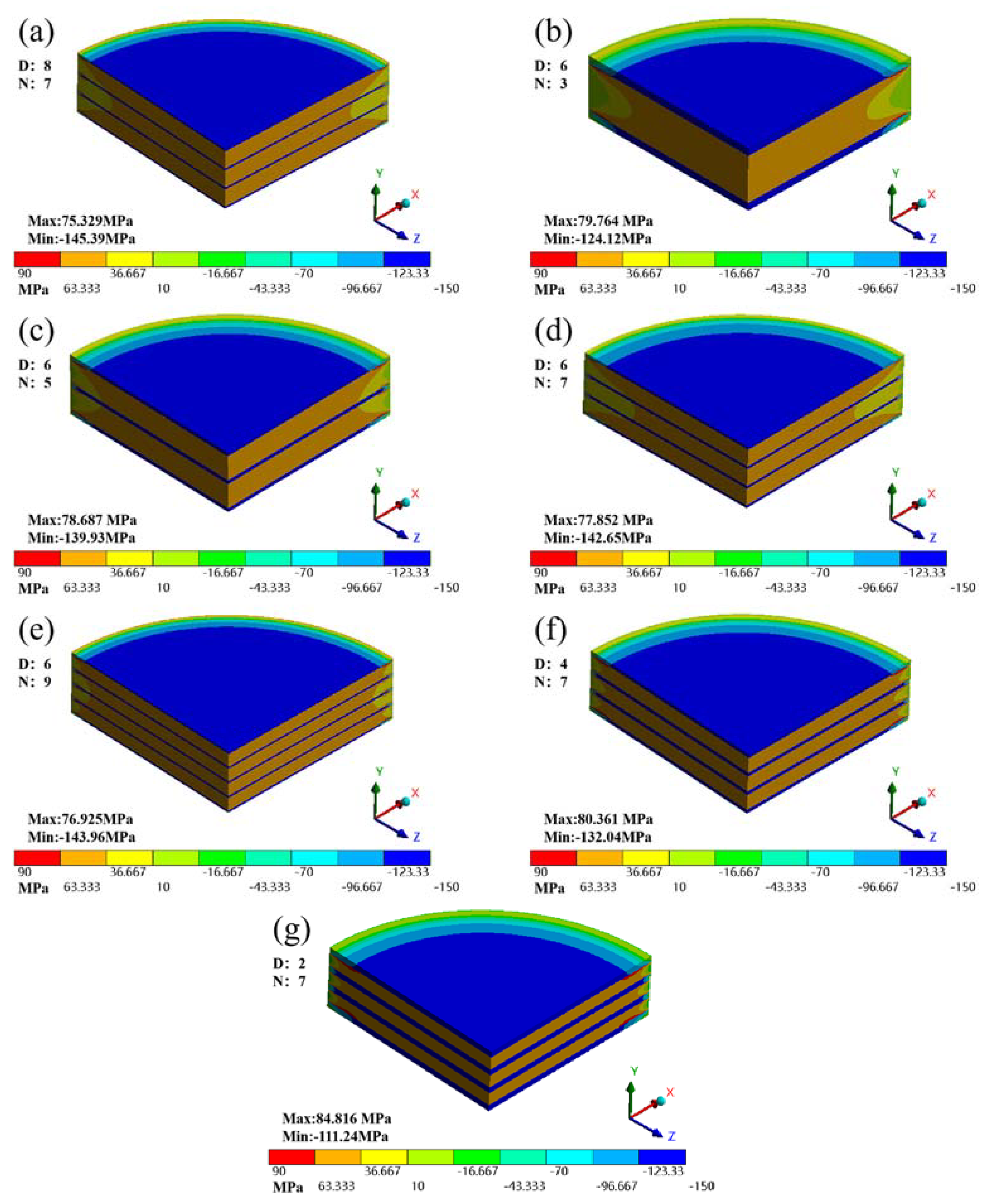
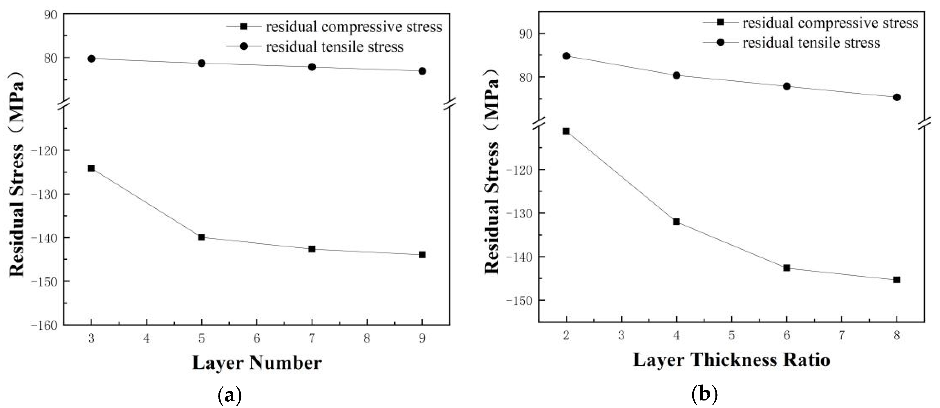
3.1. Finite Element Simulation Analysis

Figure 5 shows the radial residual stress distribution cloud of SCWAs formed during cooling. D is the number of layers and n is the layer thickness ratio. From the Figure, it can be seen that the radial residual stress presents a symmetrical distribution feature, and the tensile stress layer and the compressive stress layer show a regular alternating arrangement. The radial residual stress distribution in most areas of the Figure is relatively uniform. The stress state inside the material is relatively stable, and the stress difference in each part is small. In the boundary region, the stress distribution is uneven and the gradient is large.
Figure 6 shows the maximum radial stress of SCWA ceramic cutting tool materials with different laminated structures. As can be seen from Figure 6a, the maximum radial tensile stress shows a decreasing trend with an increase of the number of layers, but the decreasing trend is not significant. When the number of layers is 3, the stress value reaches 79.76 MPa, and when there are 9 layers, it decreases to 76.93 MPa. In contrast to tensile stress, the maximum radial compressive stress shows an increasing trend with an increase of the number of layers, but its growth rate gradually tends to be flat [28]. When the number of layers is 3, the value of the maximum radial compressive stress is 124.12 MPa. When the number of layers is 9, it increases to 143.96 MPa. From Figure 6b, the residual stresses are 84.82 MPa and −111.24 MPa for a layer thickness ratio of 2. The residual stresses are 75.33 MPa and −145.39 MPa for a layer thickness ratio of 8.
Because the surface layer makes direct contact with the workpiece, it is subjected to higher cutting forces and plays an important role in cutting performance. Therefore, an in-depth analysis was conducted on the surface layer residual stress state. As can be seen in Figure 7, in the middle part of the ceramic material, the residual stress distribution was uniform. In its boundary part, residual stresses formed a large stress gradient. Therefore, the middle part of the material should be selected when making laminated ceramic tools.
Figure 8 shows the maximum von Mises equivalent stress of SCWA ceramic tool materials. The maximum von Mises equivalent stresses generated for a layer number of 9 and a layer thickness ratio of 8 were 160.55 MPa and 162.73 MPa, respectively. It can be seen that the von Mises equivalent stress generated by laminated ceramic tool materials was not large enough to cause damage to the tool.

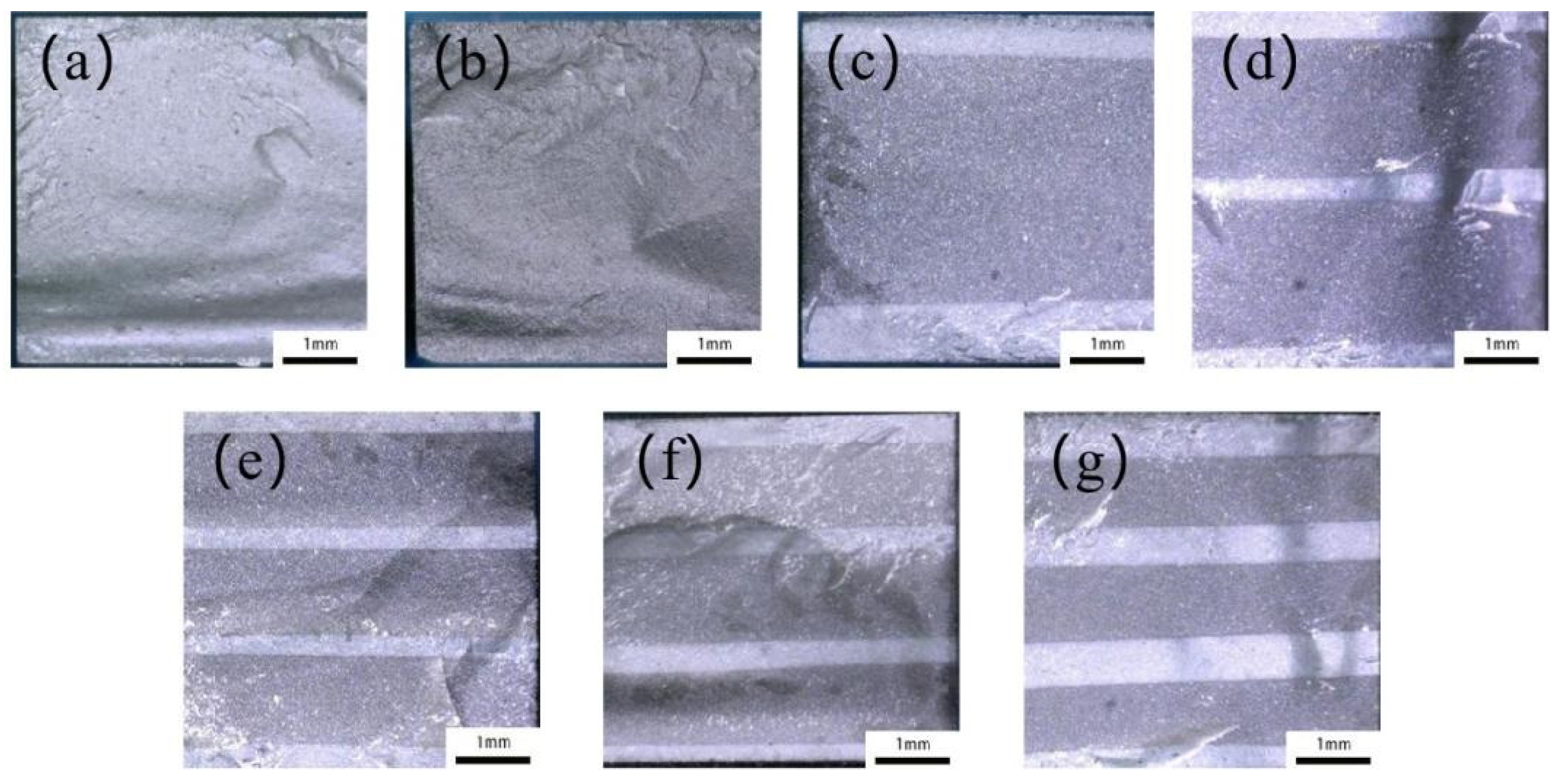
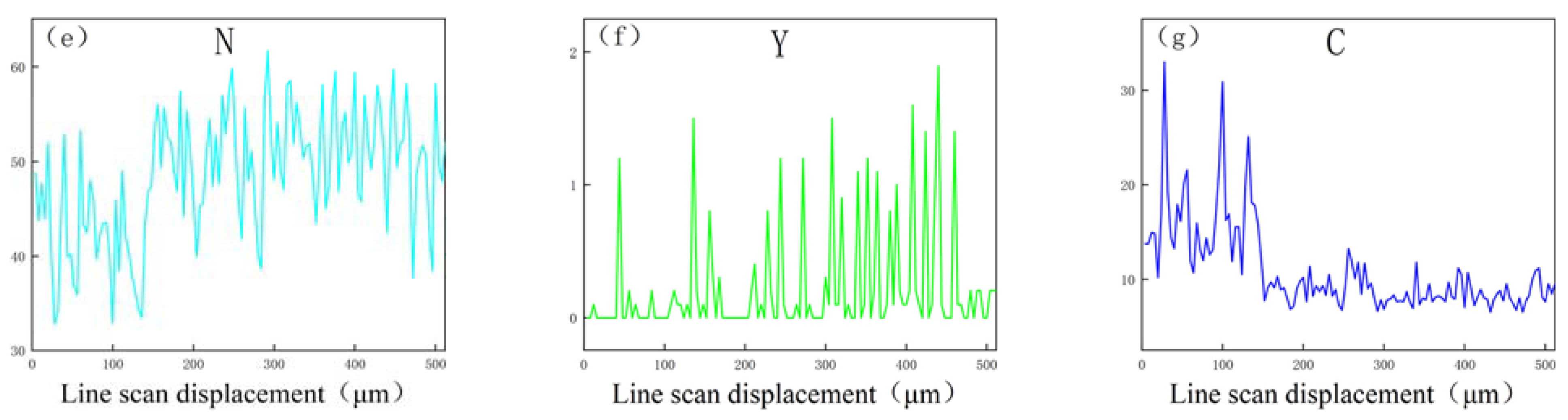
3.2. Mechanical Properties and Microstructure

Table 6 shows the mechanical properties of different ceramic tool materials. According to Table 6, the fracture toughnesses of SCWAs continued to increase with an increase in the number of layers to the layer thickness ratio. When n is 7 and D is 6, the mechanical properties of the SCW layer were optimal. The fracture toughness of the SCW layer reached 6.02 ± 0.19 MPa·m1/2. It was 14.8% higher than that of homogeneous SCW ceramic tool materials and 36.3% higher than that of homogeneous SiAlON ceramic tool materials. The fracture toughness of the SA layer also increased with a change in layer number and layer thickness ratio, but the change was not obvious at only 5.41 ± 0.18 MPa·m1/2; it was similar to the fracture toughness of homogeneous SA ceramic tool materials (5.21 ± 0.17 MPa·m1/2).
The flexural strengths of SCWAs were increased. The flexural strengths of both the front and side reached their maximum values when n is 7 and D is 6. The positive flexural strength was 602 ± 19 MPa. It was 10.7% higher than that of homogeneous SCW ceramic tool materials and 39.0% higher than that of homogeneous SiAlON ceramic tool materials. The side flexural strength was 595 ± 17 MPa, which was 25.1% higher than that of the homogeneous SA ceramic tool material. This shows that an increase in layer number and layer thickness ratio has a certain effect on improving flexural strength [28].
The Vickers hardness of the SCW layer material of SCWAs increased, but the change was not large. When n is 7 and D is 6, the Vickers hardness of the SCW layer reached its maximum, which was 19.4 ± 0.2 GPa, similar to the Vickers hardness of SCW ceramic tool materials (18.9 GPa), and only increased by 2.9%. The Vickers hardness of the SA layer material of SCWAs increased and then decreased. The range of variation was not significant and the maximum value was 18.5 ± 0.2 GPa for 5 layers. This is similar to the Vickers hardness of homogeneous SA ceramic tool materials (18.3 GPa) and shows that changes in laminated construction have little effect on Vickers hardness.
The variation trend of fracture toughness and flexural strength with the number of layers and layer thickness ratio of SCWAs was basically consistent with the trends of residual stresses in the ANSYS simulation results. This indicates that simulation analysis can be used as a guide to provide a theoretical basis for the fabrication of SCWAs. Under the influence of residual stresses, the mechanical properties of the SCW layer of SCWAs were improved and the Vickers hardness was not decreased.
Figure 9 shows optical microscope images of the morphology of the fracture surfaces of different ceramic tool materials, among which Figure 9a,b are homogeneous SCW and homogeneous SA ceramic tool materials, respectively. Figure 9c–g shows SCWAs with different layer structures. The white layer is the SCW layer and the gray layer is the SA layer. It can be seen that the interface between the layers is clear. With an increase in layer number and layer thickness ratio, the fracture plane fluctuation and the fracture surface area of the SCWA gradually increases. The fracture direction of the tool fracture changes at the junction of layers, and the fracture energy consumed by the tool fracture increases [29]. This is mainly caused by the residual stress in the SCW layer and SA layer. It indicates that the laminated structure has a certain effect on improving the mechanical properties of ceramic cutting tools.
Figure 10 shows the microstructure of the SCWA4 fracture. Figure 10a shows that the stratification between layers is obvious, and a thin transition layer is formed between the SCW layer and the SA layer. A good layered structure is obtained. Figure 10b is a local enlargement of mark 1 in Figure 10a. In the SCW layer, the grains are tightly bound, the grains grow evenly, there are more rod-like crystals, and a transgranular fracture occurs. Figure 10c is a local magnification of mark 2 in Figure 10a. It can be seen that the grains in the transition region are tightly bound and have fewer pores. Figure 10d is a local enlarged image of mark 3 in Figure 10a. It can be seen that the grains in the SA layer are tightly bound and a small amount of transgranular fracture occurs.
Figure 11 shows the fracture morphology of SCWA4 SEM morphology and line scan energy spectrum of each element. Table 7 shows the percentage of elements in different layers. The distribution of Si, Al, O, N, Y and C was studied. Figure 11b,d,f show the distribution of Si, O and Y in the online scanning area. The contents were relatively consistent across the regions and evenly distributed across the layers. Figure 11c,e show the distribution of Al and N in the online scanning area. These two elements are evenly distributed in each layer. However, the contents increase gradually along the surface layer to the matrix layer, and the distribution conforms to the rule. Figure 11g shows the distribution of C in the online scanning area. The high content of C in the surface layer is mainly due to the addition of SiC and SiCw. The presence of C was also detected in the matrix layer. This is mainly because C exists only in the surface layer, resulting in a large content gradient between layers. There is also a large stress gradient between layers, resulting in the diffusion of C from the surface layer with high carbon content to the matrix layer without C.
SCWA4 forms a surface layer of about 227 microns (SCW layer), a transition layer of about 60 microns, and a matrix layer of 1300 microns (SA layer). Si, N and Y are evenly distributed among all layers. Al and O gradually increase in content along the line scan direction, and are evenly distributed among all layers. C is mainly present within the SCW layer. Due to the diffusion of C, the matrix layer also contains some C. The distribution of elements in SCWA4 is reasonable and therefore SCWA4 has a good layered structure.

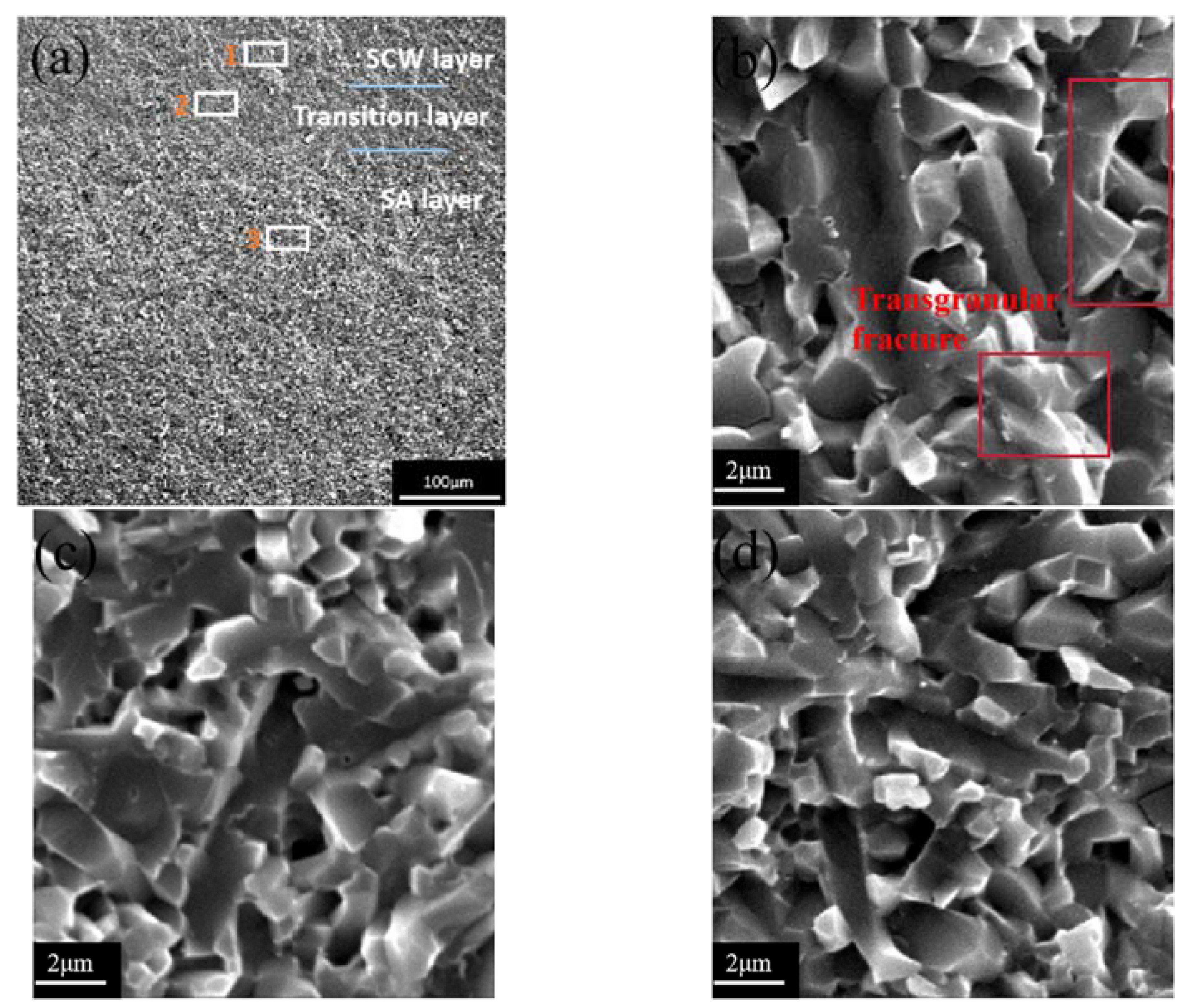
3.3. Toughening Mechanism

The indentation method [27] was used to calculate the residual stress present in SCWA4. Because of the thin thickness of the SCW layer, in order to prevent the crack from exceeding the boundary between layers and the surface fracturing at both ends, the residual stress calculation was inaccurate. Therefore, a 49 N load was applied during the indentation experiment and the pressure was held for 15 s to calculate the crack length. Figure 12a is a schematic diagram of SCWA4 indentation. If the ceramic material is evenly distributed and there is no stress interference, the crack propagation in both directions is the same. The existence of stress is the important reason for the different crack lengths in two directions of surface materials. Figure 12b,c show that the crack growth of the SCW layer is relatively long in the parallel direction of the interface, while that of the SA layer is relatively long in the perpendicular direction of the interface. The propagation distance of the crack along the two directions is different, and the material shows a certain anisotropy. It is shown that residual stress exists, and in the surface layer in the opposite direction to the matrix layer.
σ R = K I C 1 c 1 c 2 3 2 Y c R 1 2
According to the indentation crack length of each layer measured in Figure 12, the residual stress value of each layer was obtained by Formula (10) [27]. Figure 13 is a comparison diagram between the actual residual stress of SCWA4 and the residual stress obtained from the simulation analysis along the thickness direction. It can be seen from the diagram that the actual residual stress is relatively small compared with the simulation result. The stress gradually decreases from the middle part of the tool to the edge part. This is mainly due to the interlayer diffusion of the material in the sintering process, forming a transition layer; the generation of the transition layer has a buffer effect on the gradient change of stress [30]. Although this will weaken the residual stress on the tool toughening effect, the residual stress generated is still crucial for tool toughening. In addition, the formation of the transition layer indirectly strengthens the interlayer connection and avoids interlayer cracking.

4. Conclusions

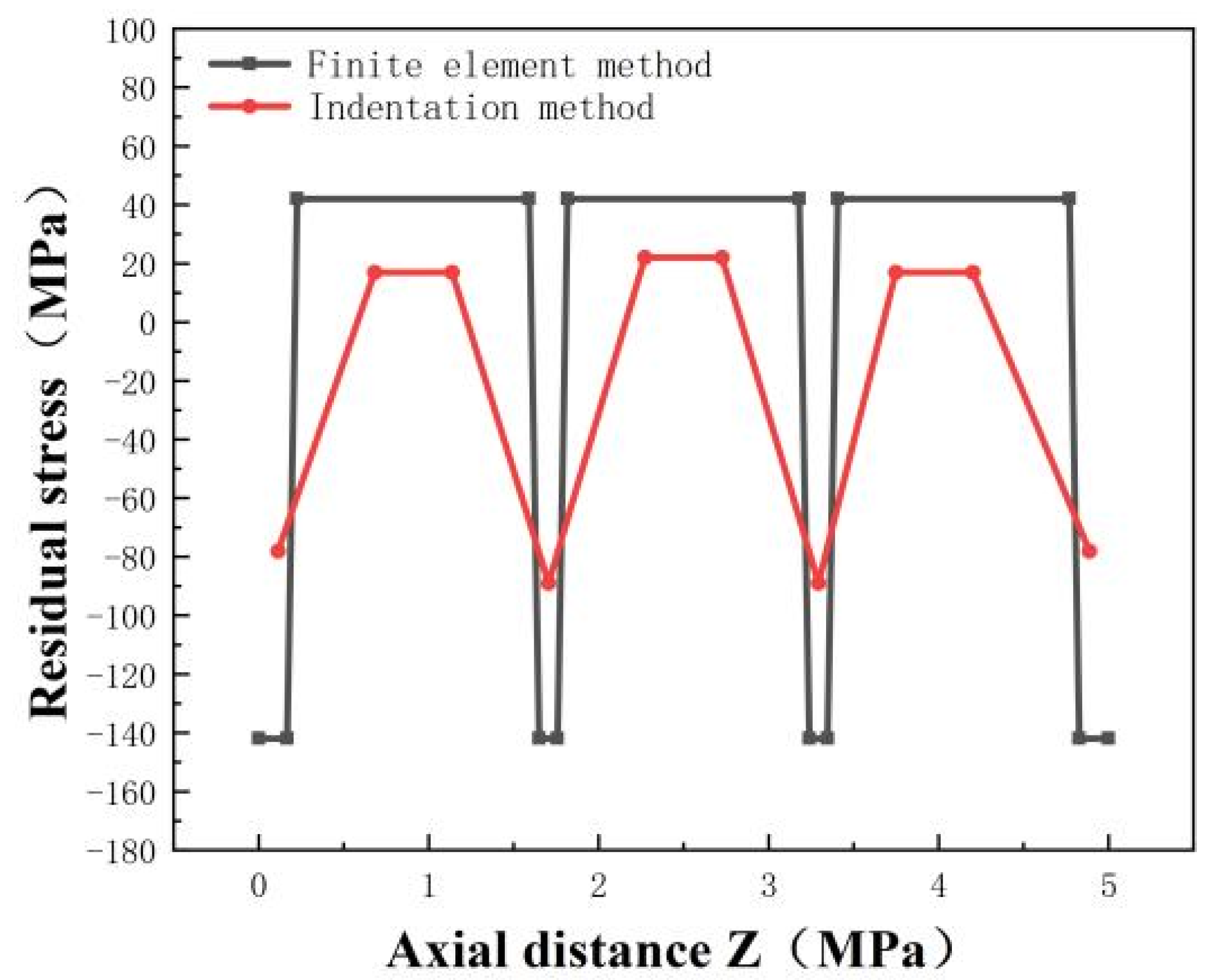
  • ANSYS simulation was used to analyze the distribution of residual stresses in SCWA ceramic tool materials as they were lowered from 1700 °C to 25 °C. The results showed that residual compressive stresses were generated in the surface layer of the material, and residual tensile stresses were generated in the matrix layer. With an increase in the number of layers and layer thickness ratio, the residual compressive stress on the surface layer also increases gradually.
  • SCWA ceramic cutting tool materials with different layer structures were experimentally prepared and the actual residual stresses in the surface and matrix layers of SCWA4 were calculated using the indentation method. The actual residual stresses are in general agreement with the ANSYS simulation analysis. This indicates that the simulation can provide guidance for actual experiments.
  • Laminated SiAlON ceramic tool materials obtained better comprehensive mechanical properties. The Vickers hardness and fracture toughness of the SCW layer in the SCWA4 ceramic cutting tool material were 19.4 ± 0.2 GPa and 6.02 ± 0.19 MPa·m1/2, respectively. The frontal and side flexural strengths were 602 ± 19 MPa and 595 ± 17 MPa, respectively.
  • The change rule of the mechanical properties of the laminated SiAlON ceramic cutting tool material was consistent with the change rule of the maximum residual compressive stress in the surface layer. This indicates that finite element analysis can provide a theoretical and technical basis for the application and research of laminated structures in composite ceramic cutting tools. Due to technical constraints, this paper prepares a limited variety of laminated structures. In the future, more complex laminated structures can be designed to research their properties and perform cutting experiments.

Author Contributions

Conceptualization, W.W., Y.J., H.C. and J.Z.; methodology, W.W., G.X, Y.J., H.C., J.Z. and M.Y.; validation, W.W.; Formal analysis, W.W.; investigation, W.W.; resources, Z.C. and C.X.; data curation, Y.J., H.C., J.Z., M.Y. and Z.C.; writing—original draft preparation, W.W.; writing—review and editing, G.X.; Visualization, G.X.; supervision, C.X.; funding acquisition, G.X. All authors have read and agreed to the published version of the manuscript.

Funding

This work funded by the National Natural Science Foundation of China (Grant No. 52075276, No. 52105192) and Key Research and Development Program of Shandong province (2023CXGC010212, 2023CXPT014).

Data Availability Statement

Data are contained within the article.

Conflicts of Interest

Author Yanjun Jia was employed by Dezhou United Petroleum Technology Corp. The remaining authors declare that the research was conducted in the absence of any commercial or financial relationships that could be construed as a potential conflict of interest.

References

  1. Oketola, A.; Jamiru, T.; Adegbola, A.T.; Ogunbiyi, O.; Rominiyi, A.L.; Smith, S. Spark plasma sintering of ceramic-reinforced binary/ternary nickel and titanium metal matrix composites: Mechanical properties, microstructure, and densification—A review. J. Alloys Metall. Syst. 2023, 3, 100031. [Google Scholar] [CrossRef]
  2. Gao, J.; Song, J.; Wang, Y.; Wang, Z.; Song, J.; Zhao, X. Microstructures and mechanical properties of functionally graded TiCN–TaC ceramics prepared by a novel layer processing strategy. Ceram. Int. 2022, 48, 16990–16996. [Google Scholar] [CrossRef]
  3. Tian, X.; Yan, K.; Zhao, J.; Cheng, Y.; Wang, Z. Thermal and mechanical shock resistances of Si3N4/(W, Ti)C graded nano-composite ceramic tool material. Ceram. Int. 2020, 46, 2317–2324. [Google Scholar] [CrossRef]
  4. Sang, G.; Zhang, Q.; Zhao, S.; Zhao, Y.; Yang, M.; Xi, X.; Yang, J. Strong and tough laminated ceramics prepared from ceramic foams. J. Eur. Ceram. Soc. 2023, 43, 2578–2585. [Google Scholar] [CrossRef]
  5. Hadraba, H.; Chlup, Z.; Drdlík, D.; Šiška, F. Characterisation of mechanical and fracture behaviour of Al2O3/ZrO2/BaTiO3 laminate by indentation. J. Eur. Ceram. Soc. 2020, 40, 4799–4807. [Google Scholar] [CrossRef]
  6. Li, S.; Wei, C.; Wang, W.; Wang, P.; Liu, Y.; Li, S.; Wen, G. Fracture toughness and R-curve behavior of laminated ZrB2–SiC/SiCw ceramic. J. Alloys Compd. 2019, 784, 96–101. [Google Scholar] [CrossRef]
  7. Liu, C.; Sun, J.; Li, G.; Li, B.; Gong, F. Fabrication, mechanical properties and fracture behaviors of the laminated Al2O3–ZrB2–MgO/Al2O3–TiN–MgO ceramic composite. Ceram. Int. 2020, 46, 857–865. [Google Scholar] [CrossRef]
  8. Zhang, Y.; Tang, C.; Zhang, Y.; Liang, Z. Fractural process and toughening mechanism of laminated ceramic composites. Acta Mech. Solida Sin. 2007, 20, 141–148. [Google Scholar] [CrossRef]
  9. Wei, C.; Zhang, X.; Hu, P.; Han, W.; Tian, G. The fabrication and mechanical properties of bionic laminated ZrB2–SiC/BN ceramic prepared by tape casting and hot pressing. Scr. Mater. 2011, 65, 791–794. [Google Scholar] [CrossRef]
  10. Cui, Y.; Chen, B.; Xiao, G.; Yi, M.; Zhang, J.; Chen, H.; Zhou, T.; Chen, Z.; Wu, J.; Xu, C. Mechanical properties and cutting performance of laminated graphene composite ceramic tools. J. Manuf. Process 2022, 81, 717–726. [Google Scholar] [CrossRef]
  11. Chen, B.; Xiao, G.; Yi, M.; Zhang, J.; Chen, H.; Zhou, T.; Chen, Z.; Xu, C. Structural design and toughening mechanism of laminated graphene ceramic tool materials. Ceram. Int. 2021, 47, 32264–32275. [Google Scholar] [CrossRef]
  12. Bitterlich, B.; Bitsch, S.; Friederich, K. SiAlON based ceramic cutting tools. J. Eur. Ceram. Soc. 2008, 28, 989–994. [Google Scholar] [CrossRef]
  13. Liu, X.; Liu, H.; Huang, C.; Zhao, B.; Zheng, L. High temperature mechanical properties of Al2O3-based ceramic tool material toughened by SiC whiskers and nanoparticles. Ceram. Int. 2017, 43, 1160–1165. [Google Scholar]
  14. Sun, J.; Zhao, J.; Chen, Y.; Wang, L.; Yun, X.; Huang, Z. Macro-micro-nano multistage toughening in nano-laminated graphene ceramic composites. Mater. Today Phys. 2022, 22, 100595. [Google Scholar] [CrossRef]
  15. Farhadi, K.; Sabahi Namini, A.; Asl, M.S.; Mohammadzadeh, A.; Kakroudi, M.G. Characterization of hot pressed SiC whisker reinforced TiB2 based composites. Int. J. Refract. Met. Hard Mater. 2016, 61, 84–90. [Google Scholar] [CrossRef]
  16. Namini, A.S.; Gogani, S.N.S.; Asl, M.S.; Farhadi, K.; Kakroudi, M.G.; Mohammadzadeh, A. Microstructural development and mechanical properties of hot pressed SiC reinforced TiB2 based composite. Int. J. Refract. Met. Hard Mater. 2015, 51, 169–179. [Google Scholar] [CrossRef]
  17. Dong, Y.; Xu, F.; Shi, X.; Zhang, C.; Zhang, Z.; Yang, J.; Tan, Y. Fabrication and mechanical properties of nano-/micro-sized Al2O3/SiC composites. Mater. Sci. Eng.: A 2009, 504, 49–54. [Google Scholar] [CrossRef]
  18. Khan, R.M.A.; Ahmed, B.A.; Al Malki, M.M.; Hakeem, A.S.; Laoui, T. Synthesis of hard and tough calcium stabilized α-SiAlON/SiC ceramic composites using nano-sized precursors and spark plasma sintering. J. Alloys Compd. 2018, 757, 200–208. [Google Scholar] [CrossRef]
  19. Son, Y.; Chung, H.B.; Lee, S. A two-dimensional Monte Carlo model for pore densification in a bi-crystal via grain boundary diffusion: Effect of diffusion rate, initial pore distance, temperature, boundary energy and number of pores. J. Eur. Ceram. Soc. 2020, 40, 3158–3171. [Google Scholar] [CrossRef]
  20. Liu, C.; Zhang, Z.; Yang, G.; Zhou, A.; Wang, G.; Qin, S.; Wang, A.; Wang, W.; Zhang, X. Finite element analysis and wear mechanism of B4C–TiB2 ceramic tools in turning AISI 4340 workpieces. Ceram. Int. 2022, 48, 5459–5467. [Google Scholar] [CrossRef]
  21. Low, I.M. (Ed.) 1—Advances in ceramic matrix composites: Introduction. In Advances in Ceramic Matrix Composites; Woodhead Publishing: Sawston, UK, 2018; pp. 1–7. [Google Scholar]
  22. Wang, Y.; Wang, H.; Wei, J.; Lin, B.; Xu, J.; Fang, S. Finite element analysis of grinding process of long fiber reinforced ceramic matrix woven composites: Modeling, experimental verification and material removal mechanism. Ceram. Int. 2019, 45, 15920–15927. [Google Scholar] [CrossRef]
  23. Zhang, S.; Yan, L.; Gao, K.; Yang, H.; Wang, Y. Finite element analysis of the effect of TiC or graphite modified composite fillers on the thermal residual stress of AMB ceramic substrates. Ceram. Int. 2019, 45, 19098–19104. [Google Scholar] [CrossRef]
  24. Gao, J.; Song, J.; Ping, P.; Meng, W. Effect of sintering temperature on residual stress, microstructure and mechanical properties of TiC–HfN/TiC–TiN laminated ceramic. Ceram. Int. 2023, 49, 38432–38438. [Google Scholar]
  25. Burlachenko, A.G.; Mirovoi, Y.A.; Dedova, E.S.; Buyakova, S.P. Mechanical Response of ZrB2–SiC–ZrO2 Composite Laminate. Russ. Phys. J. 2019, 62, 1438–1444. [Google Scholar] [CrossRef]
  26. Doitrand, A.; Estevez, R.; Leguillon, D. Comparison between cohesive zone and coupled criterion modeling of crack initiation in rhombus hole specimens under quasi-static compression. Theor. Appl. Fract. Mech. 2019, 99, 51–59. [Google Scholar] [CrossRef]
  27. dos Reis Araújo, M.; Hotza, D.; Janssen, R.; Acchar, W. Processing and properties of tape-cast alumina/zirconia laminates composites. J. Eur. Ceram. Soc. 2019, 39, 3462–3465. [Google Scholar] [CrossRef]
  28. Zhu, J.; Zhou, H.; Qin, B.; Zhao, Z. Design, fabrication and properties of TiB2/TiN/WC gradient ceramic tool materials. Ceram. Int. 2020, 46, 6497–6506. [Google Scholar] [CrossRef]
  29. Ji, W.; Zou, B.; Huang, C.; Liu, Y.; Huang, C. Fabrication, microstructure and mechanical properties of self-diffusion gradient cermet composite tool materials. Mater. Sci. Eng.: A 2017, 685, 332–341. [Google Scholar] [CrossRef]
  30. Hu, S.; Song, J.; Gao, J.; Liu, J.; Meng, W.; Wang, Y. Effect of layer thickness ratio on microstructure and mechanical properties of TiCN–HfN/TiCN–WC laminated ceramics. Ceram. Int. 2023, 49, 20763–20771. [Google Scholar] [CrossRef]
Figure 1. Schematic of SCWAs.
Coatings 14 01218 g001
Figure 2. The finite element model: (a) the finite element model of SCWA4, (b) the finite element meshing diagram of SCWA4.
Coatings 14 01218 g002
Figure 3. Flow chart of finite element analysis of residual stress of SCWAs.
Coatings 14 01218 g003
Figure 4. Schematic diagram of the testing method for the mechanical properties of SCWAs.
Coatings 14 01218 g004
Figure 5. Radial stress distribution: (a) SCWA1, (b) SCWA2, (c) SCWA3, (d) SCWA4, (e) SCWA5, (f) SCWA6, (g) SCWA7.
Coatings 14 01218 g005
Figure 6. Relation of maximum radial stress to the number of layers and layer thickness ratio: (a) layer number, (b) layer thickness ratio.
Coatings 14 01218 g006
Figure 7. Relation between layer number, layer thickness ratio and surface residual stress along the radius direction: (a) layer number, (b) layer thickness ratio.
Coatings 14 01218 g007
Figure 8. The relationship between the maximum von Mises equivalent stress and the number of layers and the layer thickness ratio: (a) layer number, (b) layer thickness ratio.
Coatings 14 01218 g008
Figure 9. Optical microscope images of the morphology of the fracture surfaces of the ceramic materials: (a) homogeneous SCW, (b) homogeneous SA, (c) SCWA2, (d) SCWA3, (e) SCWA4, (f) SCWA6, (g) SCWA7.
Coatings 14 01218 g009
Figure 10. SEM microstructure of SCWA4 fracture surface: (a) SCWA4, (b) SCW layer, (c) transition layer, (d) SA layer.
Coatings 14 01218 g010
Figure 11. Energy spectrum of SCWA4: (a) scanning line direction, (b) Si, (c) Al, (d) O, (e) N, (f) Y, (g) C.
Coatings 14 01218 g011aCoatings 14 01218 g011b
Figure 12. Indentation of SCWA4: (a) indentation diagram, (b) SCW layer, (c) SA layer.
Coatings 14 01218 g012
Figure 13. Residual stress of SCWA4 along the thickness direction.
Coatings 14 01218 g013
Table 1. Details of raw material powders.
PowderPurity (%)Average Particle Size (μm)Supplier
Si3N499.90.5Shanghai CW-Nano Science & Technology Co., Ltd., Shanghai, China
Al2O399.90.2
AlN99.90.5
Y2O399.90.5
SiC99.90.5
SiCw99.9D0.5, L10
Table 2. Compositions of the SCW layer and SA layer.
MaterialsComposition (wt%)
Si3N4Al2O3AlNY2O3SiCSiCw
SCWSiAlON/SiC/SiCw50.991.7911.626.6209
SASiAlON/Al2O366.0910.3314.998.5900
Table 3. Physical properties of the raw materials.
MaterialsThermal Expansion
Coefficient
α   ( 10 6 · K 1 )
Elastic
Modulus (GPa)
Poisson’s
Ratio   ( ν )
Thermal
Conductivity λ (W·m−1·K−1)
Si3N42.753720.2420
Al2O38.53800.2640.37
AlN4.53200.2620
Y2O35.82200.2827
SiC4.54400.1444
SiCw4.354400.1745
Table 4. Physical properties of the SCW layer and SA layer.
MaterialsThermal Expansion
Coefficient
α   ( 10 6 · K 1 )
Elastic
Modulus (GPa)
Poisson’s
Ratio   ( ν )
Thermal
Conductivity λ (W·m−1·K−1)
SCW3.573750.2226.15
SA3.673550.2521.96
Table 5. Details of structures of SCWAs.
MaterialsLaminated StructuresSA/SCW Thickness Ratio (D)Number of Layer (n)
SCWA1SCW + SA + SCW + SA + SCW + SA + SCW87
SCWA2SCW + SA + SCW63
SCWA3SCW + SA + SCW + SA + SCW65
SCWA4SCW + SA + SCW + SA + SCW + SA + SCW67
SCWA5SCW + SA + SCW + SA + SCW + SA + SCW + SA + SCW69
SCWA6SCW + SA + SCW + SA + SCW + SA + SCW47
SCWA7SCW + SA + SCW + SA + SCW + SA + SCW27
Table 6. Mechanical properties of the ceramic materials.
MaterialsFracture Toughness (MPa·m1/2)Flexural Strength (MPa)Vickers Hardness (GPa)
SiAlON4.85 ± 0.19433 ± 917.89 ± 0.16
SCW5.76 ± 0.18544 ± 2118.89 ± 0.21
SA5.21 ± 0.17475 ± 2218.34 ± 0.19
SCWSAFrontSideSCWSA
SCWA25.97 ± 0.165.28 ± 0.18565 ± 21551 ± 1819.1 ± 0.218.4 ± 0.2
SCWA36.35 ± 0.175.35 ± 0.17583 ± 17572 ± 2119.2 ± 0.218.5 ± 0.2
SCWA46.61 ± 0.195.41 ± 0.18602 ± 19595 ± 1719.4 ± 0.218.2 ± 0.2
SCWA66.42 ± 0.175.36 ± 0.17582 ± 17576 ± 2119.1 ± 0.218.5 ± 0.2
SCWA76.25 ± 0.165.29 ± 0.18571 ± 21561 ± 1818.9 ± 0.218.4 ± 0.2
Table 7. Distribution of elements in the SCW and SA layers.
ElementsComposition (wt%)
(SCW Layer)
Composition (wt%)
(SA Layer)
Si21.0521.22
Al3.267.62
O2.282.44
N13.3119.96
Y3.503.58
C1.620.16
Disclaimer/Publisher’s Note: The statements, opinions and data contained in all publications are solely those of the individual author(s) and contributor(s) and not of MDPI and/or the editor(s). MDPI and/or the editor(s) disclaim responsibility for any injury to people or property resulting from any ideas, methods, instructions or products referred to in the content.

