Article

Beam Plasma Source-Enhanced Deposition of Hydrophobic Fluorocarbon Thin Films

1
Department of Chemical Engineering and Materials Science, Michigan State University, East Lansing, MI 48824, USA
2
Fraunhofer USA Center Midwest, East Lansing, MI 48824, USA
3
Department of Electrical and Computer Engineering, Michigan State University, East Lansing, MI 48824, USA
*
Authors to whom correspondence should be addressed.
Coatings 2025, 15(1), 110; https://doi.org/10.3390/coatings15010110
Submission received: 17 December 2024 / Revised: 14 January 2025 / Accepted: 17 January 2025 / Published: 19 January 2025
(This article belongs to the Section Plasma Coatings, Surfaces & Interfaces)

Abstract

:
Fluorocarbon thin films are widely used in protective coatings due to their distinctive physical and chemical properties. However, their inherent lubricating nature often results in low scratch resistance and poor adhesion to substrates. In this study, a beam plasma source was employed to deposit fluorocarbon thin films, resulting in enhanced adhesion and scratch resistance while preserving optical transmittance and hydrophobicity. The beam plasma source can generate high-density plasma, resulting in the effective dissociation of the C4F8 source gas, as evidenced by the large ion current and high film deposition rates. A unique feature of this beam plasma source is that it can simultaneously emit a single broad beam of ions with independently controllable ion energy and flux to interact with the film. The fluorocarbon films exhibit high hydrophobicity with a contact angle of about 105°, a high optical transmittance of 85–90% in the visible wavelength range, and exceptional scratch resistance and durability.

1. Introduction

Plasma treatment is widely used for modifying surface properties due to its excellent controllability and efficiency [1]. Among the various surface treatments, fluorocarbon coatings provide many extreme properties, including chemical inertness, thermal stability, low friction coefficient, and low dielectric constant [2]. These unique properties result in numerous applications, such as anti-corrosion coatings, moisture barriers, and solar panels [2,3,4].
Fluorocarbon thin films can be deposited by many different techniques, such as dielectric barrier discharge, synchrotron radiation irradiation, magnetron sputtering, and plasma polymerization [5,6,7,8]. Obtaining the high hydrophobicity of a coated surface is one of the most essential properties of fluorinated films. The desired wettability can be met by facilitating the formation of F radicals, which can reduce the surface energy due to the dominance of the non-polar component [9]. However, ascribed to a low-friction property, the adhesion strength of fluorinated thin films to substrate materials is rather poor and causes the film to crack or peel off [10,11].
This paper reports on a new beam plasma source enhanced by chemical vapor deposition to address the adhesion problem and maintain the inherent properties of fluorocarbon thin films. The beam plasma source enables the efficient dissociation of octafluorocyclobutane (C4F8) precursor gas and simultaneously emits ions with controllable energy to treat the deposited film [12]. The coating adhesion, wear resistance, wettability, optical transmittance and reflectance, and refractive index are investigated. This study has shown that the beam plasma source deposited by fluorocarbon thin films possesses scratch resistance with high transparency and hydrophobicity.

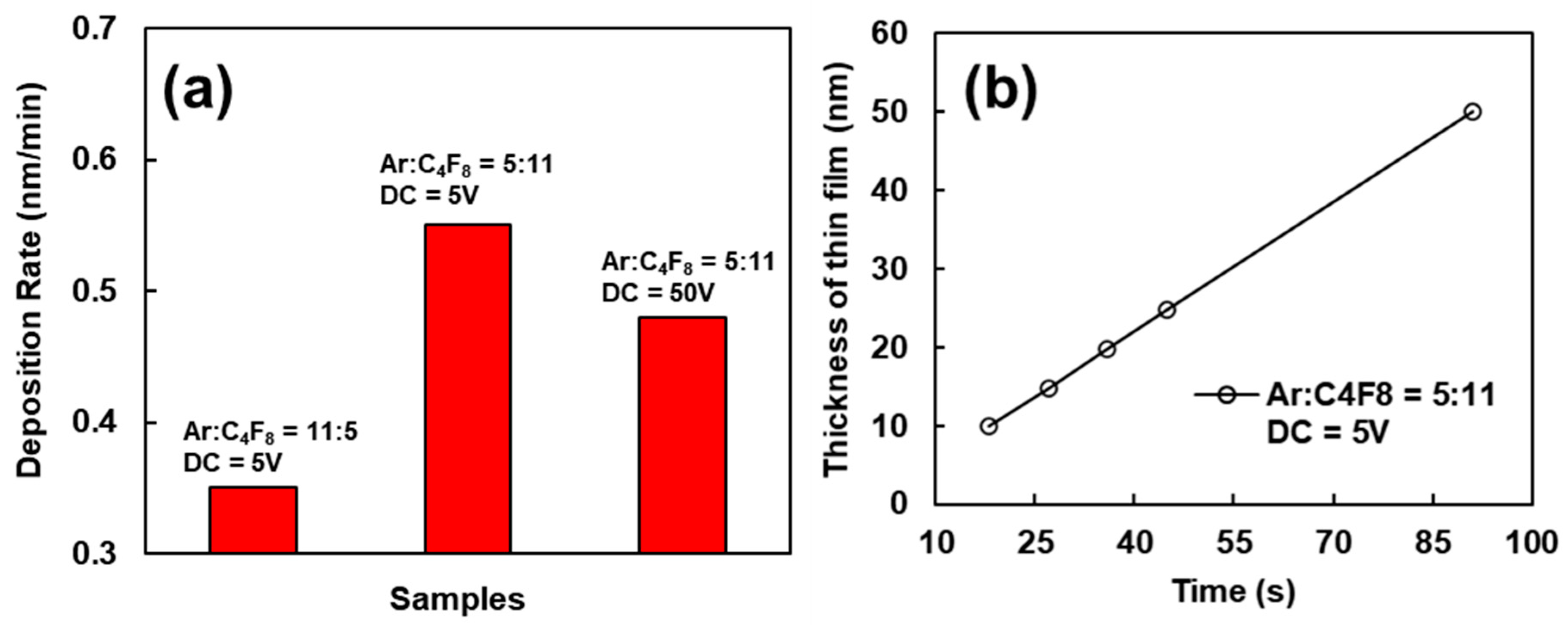
2. Materials and Methods

Glass and silicon slides of 2.5 × 2.5 cm2 and 1 mm thickness were used as substrates. The silicon substrates were used for spectroscopic ellipsometry analysis. Both substrates were cleaned via ultrasonication in acetone and DI water, followed by drying in an oven at 80 °C for 30 min. A custom-made vacuum system was used for the plasma-enhanced chemical vapor deposition of fluorocarbon thin films. A beam plasma source (SPR-100, Scion Plasma LLC.) was installed from a top flange. The operational principle of the broad beam ion source SPR-100 is illustrated in Figure 1. The ion source consists of a broad anode with a magnetic field distributed above the anode. The surrounding cathode intercepts a substantial portion of the magnetic flux, enabling the effective confinement of the energetic electrons to sustain the discharge. A positive voltage is applied to the anode relative to the cathode to ignite plasma. As an electron is accelerated toward the anode, it experiences a Lorenz force and subsequently drifts in the E×B direction above the anode surface. Under steady discharges, there is a gradual drop in the electric potential from the anode to the substrate, creating an electric field that drives positively charged ions as a single broad beam toward the substrate. The ion source discharge can be sustained by direct current (DC) power and/or radio frequency (RF) power. The strong confinement of the electrons by the magnetic field across the anode surface results in a high ion flux density.
Before the film’s deposition, the chamber was pumped down below 3 × 10⁻⁵ Torr. The deposition process utilized Ar and C4F8 gasses. The process pressure was maintained at 1 × 10⁻³ Torr. The films were deposited at room temperature without external heating. During deposition, the substrate temperature was below 40 °C, as measured by a thermocouple set underneath the substrate. The beam plasma source was excited by 80 W RF power superimposed on a DC voltage of 5–50 V. For each sample, the deposition time was based on the film growth rate to achieve the desired film thickness. The deposition rates were determined from a set of pre-depositions.
The ion energy was measured using an Impedans Semion system. The film thickness was measured using a step profilometer (Dektak 150), and it was confirmed using a spectroscopic ellipsometer (M2000, JA Woollam). The ellipsometer was also used to characterize the refractive index and extinction coefficient (n,k) of the deposited fluorocarbon thin films. The films used for ellipsometry analysis were deposited on the silicon wafer. A single-layer model, including a silicon substrate and a Cauchy layer, was used when fitting the films. The film transmittance and reflectance were assessed with a spectrophotometer (F20, Filmetics). This instrument can be configured into a transmission mode or a reflection mode, which can be calibrated through baseline measurements. The plasma species were monitored using optical emission spectroscopy (Flame 4000, Ocean Optics). Wettability was determined using the contact angle measurement (VCA-Optima). X-ray photoelectron spectroscopy (XPS) was carried out using a Perkin Elmer Phi 5600 ESCA system with a magnesium Kα x-ray source at 1253.6 eV and the binding energies were corrected referring to the standard carbon peak C 1s (284.8 eV). The fitting of peaks was performed using CasaXPS software. The Shirley background was applied in the XPS data analysis, while a combination of both Lorentzian and Gaussian line shape functions was used for spectrum fitting. Film scratch resistance was evaluated by a pencil hardness tester (3004N11, McMaster Carr).

3. Results and Discussion

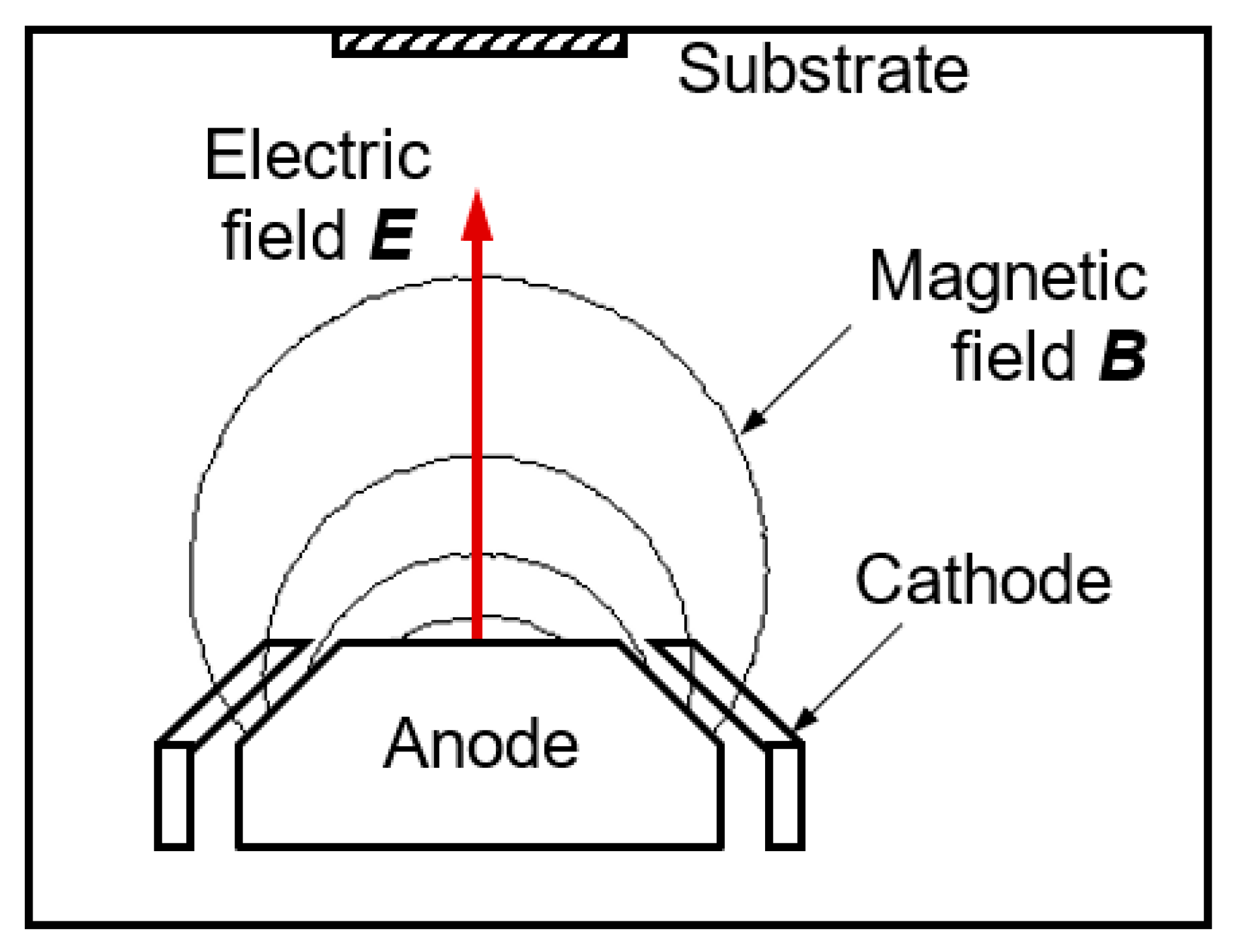
3.1. Beam Plasma Source Characteristics

Figure 2a shows the plasma source discharge image. This plasma source can be excited using RF, DC, or RF+DC powers. The combined DC and RF discharge is advantageous to conventional ion sources by allowing independent control of the ion energy and ion current, as shown in Figure 2b,c. By changing the DC voltage from 0 to 120 V, the ion energy is almost independent of the RF power and changes almost linearly from ~50 eV to 120 eV. On the other hand, the ion current can be mainly modulated by RF power. Under a fixed DC voltage, the ion current increases with RF power. These features are unique and highly desirable. On the one hand, it is possible to create high-density plasma using RF power, allowing high deposition rates. On the other hand, the ion energy can be controlled to relatively low values, which is essential for fluorocarbon thin film deposition. It was found that a high DC voltage of over 100 V could damage the film due to the energetic ion bombardments. Therefore, all the films in this study were prepared with a DC voltage below 50 V. In addition, the power supply current had a limit of 1 A. Therefore, all the processes used an RF power of 80 W, although this plasma source could handle much higher power and current. It is worth noting that the ion energies were measured using an ion analyzer, which represents a conductive substrate. On the other hand, glass substrates were used in this work, and the films were insulators. It has been reported that ion energy can be reduced if the substrate is an insulator [13].

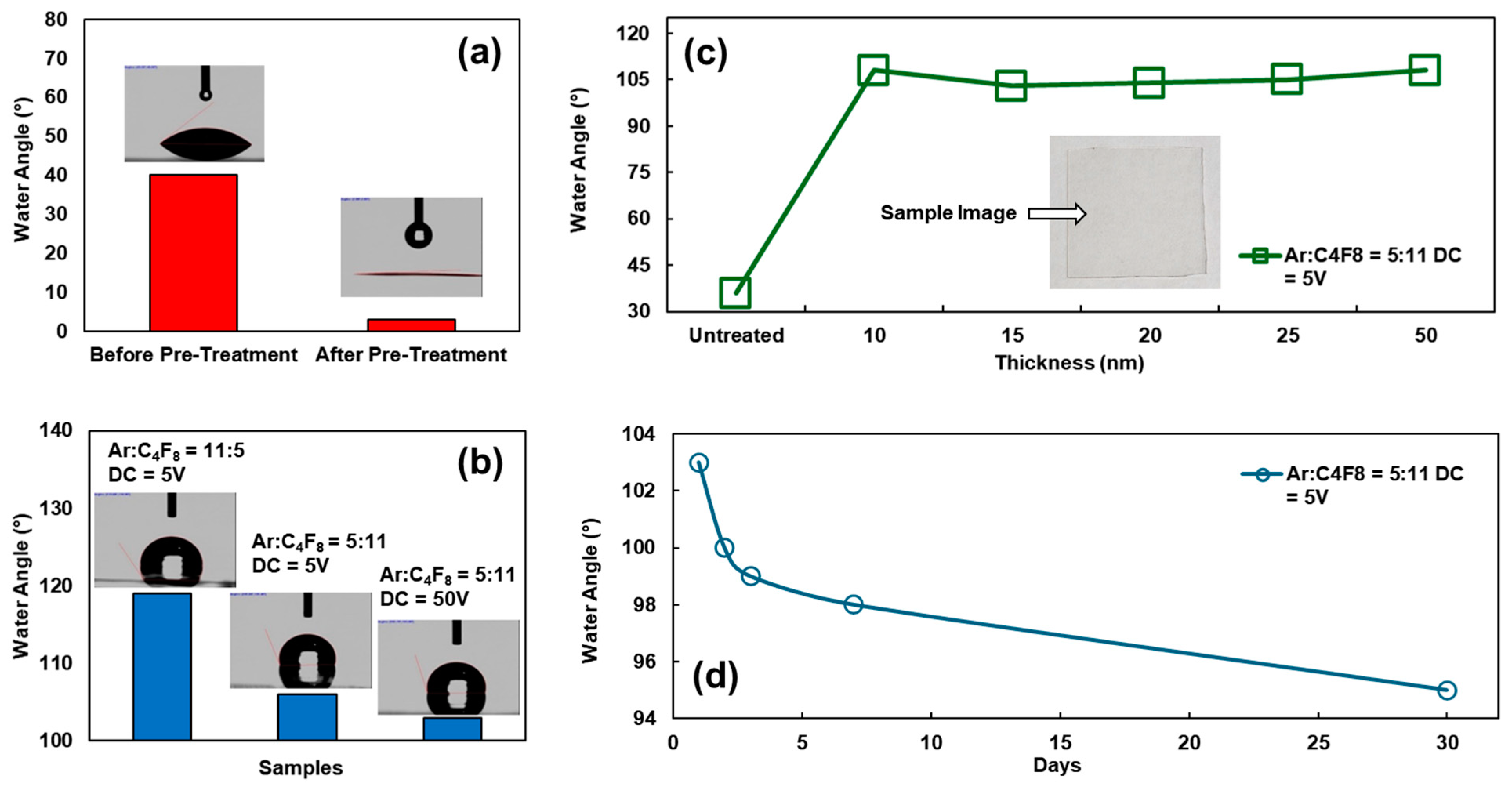
3.2. Wettability of Fluorocarbon Thin Films

Figure 3a displays how the bare glass substrate initially had a contact angle of 40°, which decreased to 3° after pure Ar plasma pre-treatment for 2 min. This reduction in the contact angle was due to argon plasma interactions with the substrate, enhancing the surface energy by removing contaminants [9]. This pre-treatment was applied to all the samples before depositing the fluorocarbon film to ensure a consistent substrate surface condition.
The influence of different gas ratios and ion energies on the surface wettability was investigated. In Figure 3b, all the thin films had a thickness of 100 nm, showing that deposition with a dominant Ar gas of Ar:C4F8 = 11:5 (with the flow unit of sccm, which is the same unit for the gas ratio mentioned later) resulted in slightly better hydrophobicity compared to a higher ratio of C4F8 gas. This is attributed to the increased gas ionization because Ar is easier to ionize than C4F8. The increased plasma density promotes the formation of CF2 and CF3 monomer groups. These groups result in a decrease in the surface energy [14,15]. On the other hand, varying the DC voltage from 5 to 50 V led to a slightly smaller contact angle (106° vs. 103°). This result implies that intensive ion bombardments could break C-F bonds and/or create surface defects, resulting in slightly increased surface energy.
The fluorocarbon coatings’ wettability was monitored for over one month. Figure 3d shows that the fluorocarbon thin films remain stable on the glass substrate, as evidenced by only a slight drop of 8° in the contact angle after one month of exposure to air. This stability can be attributed to the strong chemical bonding of F radicals to the substrates, which greatly reduces the surface tension.
Fluorocarbon thin films of different thicknesses were prepared with a fixed Ar:C4F8 gas ratio of 5:11 and a DC voltage of 5 V. The film thickness could be controlled by the deposition conditions and time, as shown in Figure 4a,b. It is worth noting that the deposition rates decreased slightly as the DC voltage increased. This can be ascribed to the increased argon ion energy at higher DC voltages. Energetic argon ions could remove some deposited carbon and C-F species. Combining the film thickness with the contact angles shown in Figure 3c, it can be concluded that the film thickness had nearly no impact on the contact angle. This result implies that the surface C-F bonds contribute to hydrophobicity. Therefore, an ultra-thin fluorocarbon film of ~15 nm is sufficient to create a superhydrophobic surface.

3.3. OES Characterization

Optical emission spectroscopy revealed that various species (e.g., CF2, C2, C3, and F) were created in the plasma, as displayed in Figure 5a. Hence, CF2 and F play a key role in interacting with the surface and forming fluorocarbon coatings. The typical dissociation reactions of C4F8 plasma are outlined in Equations (1)–(8) below [16,17], which imply that most long-chain C-F species (e.g., C3F6 and C2F4) are only intermediate products of a low fraction [18,19]. XPS analysis confirmed the chemical bonding of the deposited films, as shown in Figure 5b. Several typical peak locations included 292 eV attributed to CF2, 290.5 eV attributed to CF-CF, and 286.5 eV attributed to C-CFx. The XPS analysis confirmed the presence of F radicals on the film surface, which is responsible for the hydrophobic characteristics. It is important to note that argon ions can preferentially remove amorphous carbon from the substrate surface, allowing the films to maintain high transparency and achieve high hydrophobicity by mainly depositing CFx on the surface.
C 4 F 8 + e   2 C 2 F 4 + e
C 4 F 8 + e   C 3 F 6 + C F 2 + e
C 3 F 6 + e   C 2 F 4 + C F 2 + e
C 2 F 4 + e   2 C F 2 + e
C 4 C 2 F 4 + e   C 2 F 3 + F + e
C 2 F 4 + F   C F 2 + C F 3
C F 2 + e   C F + F + e
C F + e   C + F + e

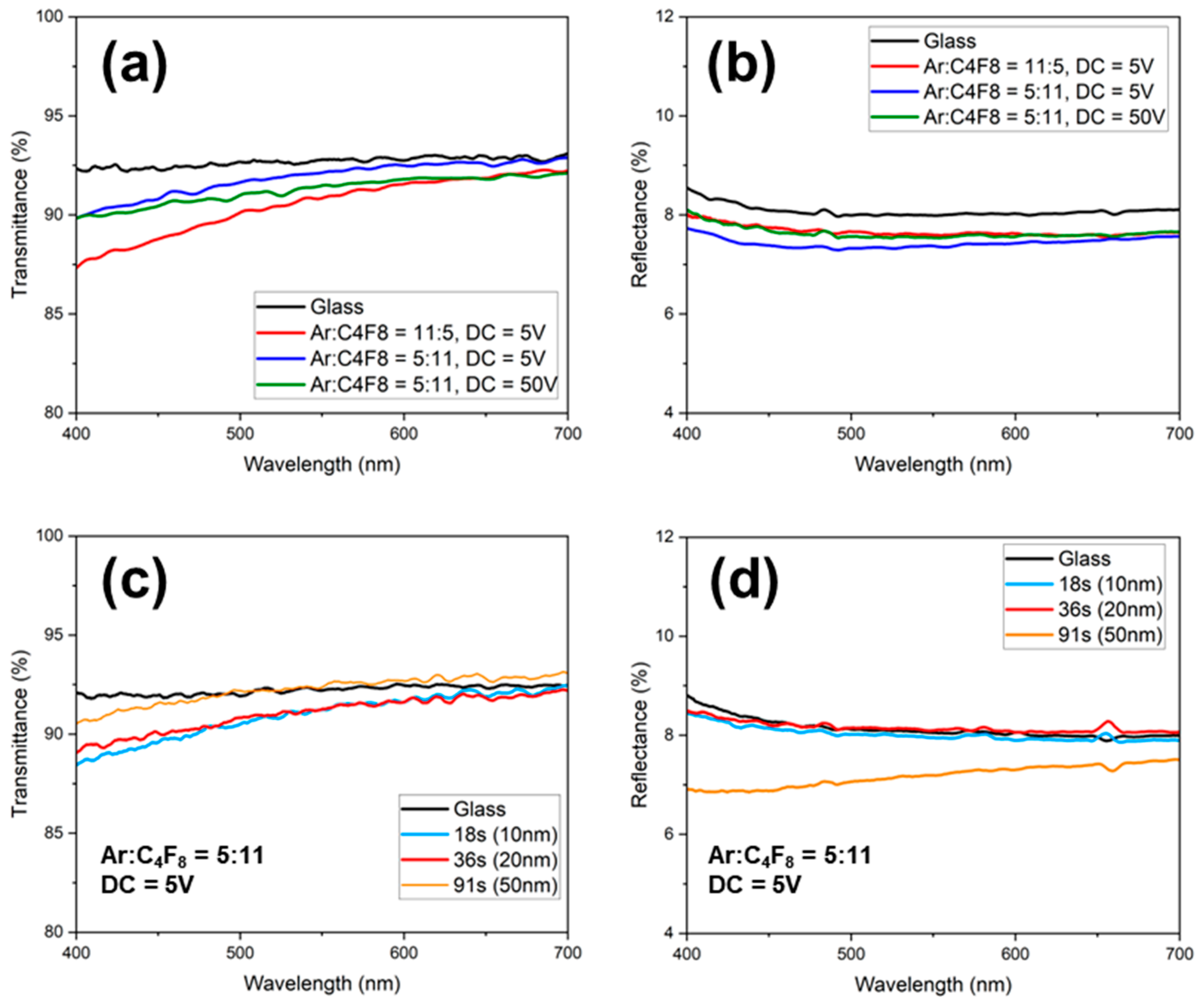
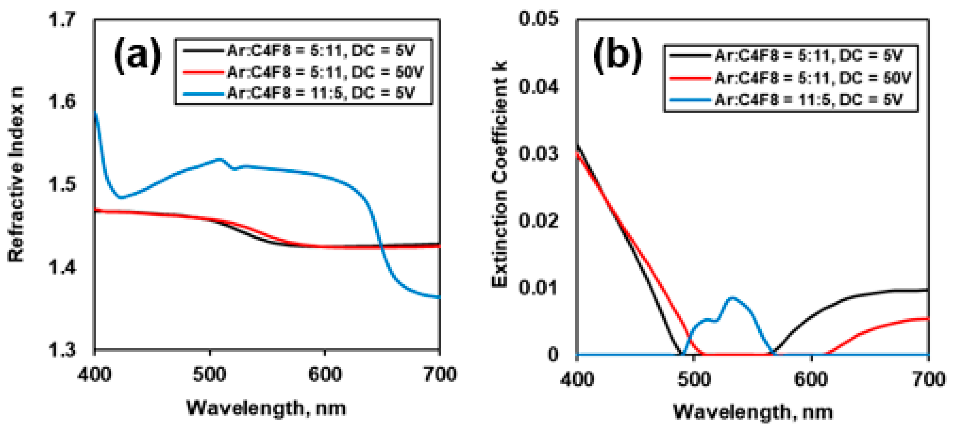
3.4. Optical Properties

The transmittance and reflectance spectra of the fluorocarbon coatings on glass are shown in Figure 6. In general, the films were highly transparent to visible light. The film transmittance and reflectance in the short wavelength range of <450 nm decreased slightly as the Ar:C4F8 ratio changed from 11:5 to 5:11 (see Figure 6a,b). This was likely due to the enhanced gas ionization and dissociation under a higher Ar concentration, which could create carbon species. The DC voltage had little effect on the film transmittance. As the DC voltage increased from 5 to 50 V, the film transmittance nearly did not change, and the reflectance near 320 nm increased slightly (<1%). This could be caused by ion bombardments, which break C-F bonds and/or create surface defects, as discussed before. Varying the film thickness, the transmittance nearly did not change, while the reflectance decreased slightly (see Figure 6c,d).
The refractive indices of the fluorocarbon films are generally close to that of the glass. The Ar:C4F8 gas ratio has a more obvious effect on the film refractive index and extinction coefficient, as shown in Figure 7a,b; a higher Ar:C4F8 ratio (e.g., 11:5) resulted in larger n values. This is mainly attributed to a change in film composition and morphology. A higher Ar:C4F8 ratio causes more argon ion bombardments on the film and a slow deposition rate, enabling the formation of a denser film. On the other hand, the DC voltage (ion energy) nearly does not influence the refractive index. These results are consistent with the deposition rates shown in Figure 4. Based on Figure 6, the sum of the films’ transmittance and reflectance, regardless of the deposition parameters, is almost equal to 100%. It indicates that the film absorption is negligible, making it highly transparent. This is further underpinned by the extinction coefficient k, which is generally very small (<0.03) over the visible range.

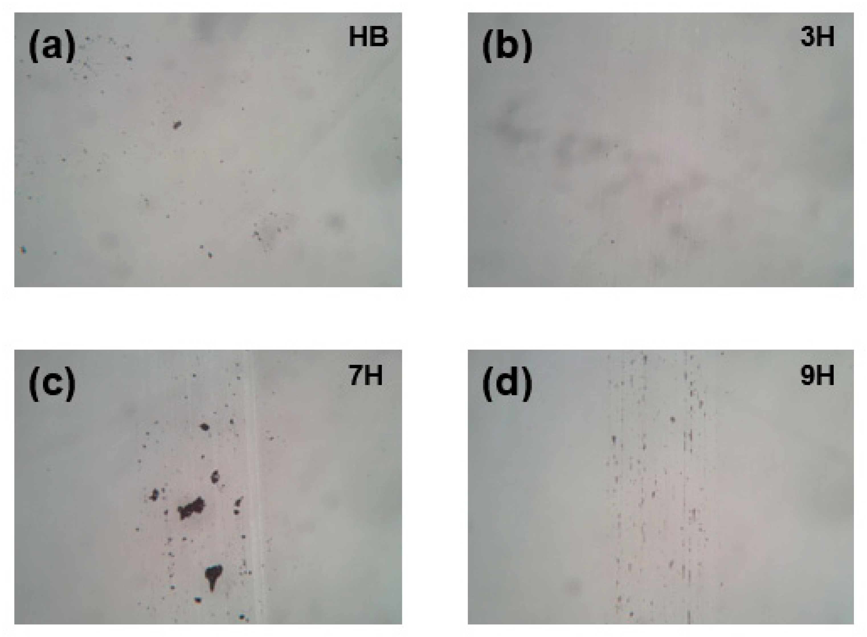
3.5. Scratch Resistance

Scratch resistance is an important factor for fluorocarbon film applications, such as display screens and smart windows [20]. Pencil scratch tests were conducted at least five times in different areas on the surface of each fluorocarbon coating of ~15 nm thickness deposited with an Ar:C4F8 gas ratio of 5:11 at 5 V DC voltage. Figure 8 shows the microscopic images of the substrate surface tested with pencils of various hardness of HB, 3H, 7H, and 9H. Even at the maximum hardness of 9H, the thin film still adhered to the substrate without visible delamination. The black spots on the images are debris from the pencil tips, which further indicate strong films and coating adhesion. This is ascribable to the fact that the beam plasma source enables dense fluorocarbon coatings on the glass substrate, which is hard to achieve using conventional deposition techniques.

4. Conclusions

This work reports a beam plasma source-enhanced chemical vapor deposition of fluorocarbon thin films using mixed argon and octafluorocyclobutane (C4F8) gasses, aiming to achieve high hydrophobicity, optical transparency, and scratch resistance. The plasma source allows for the independent control of the ion energy and ion current. The films are highly transparent with transmittance at 85–90% in the visible range and are hydrophobic with a contact angle of 103–119°. The Ar:C4F8 gas ratio affects the hydrophobicity and transmittance. A lower Ar:C4F8 ratio results in slightly higher transmittance in the short wavelength range of <450 nm and a slightly lower contact angle. Changing the ion energy from about 50 eV to 80 eV nearly has no effect on the film transmittance and hydrophobicity. The optical transmittance and reflectance of the fluorocarbon films are consistent with the refractive index results, showing that the Ar:C4F8 gas ratio is the primary factor that affects the refractive index. The fluorocarbon films of different thicknesses from 15 to 100 nm exhibit similar stable hydrophobicity. Even the thinnest film of 15 nm possesses a strong resistance to 9H pencil scratches.

Author Contributions

Conceptualization: J.L.; methodology: J.L. and Q.H.F.; data curation: J.L. and C.M.; writing—review and editing: J.L., K.W. and Q.H.F.; supervision: Q.H.F. and K.W.; funding acquisition, Q.H.F. All authors have read and agreed to the published version of the manuscript.

Funding

This work was supported by the National Science Foundation award number 2243110. We also acknowledge the MTRAC Advanced Applied Materials program.

Institutional Review Board Statement

Not applicable.

Informed Consent Statement

Not applicable.

Data Availability Statement

The data presented in this study are contained within the article.

Conflicts of Interest

The authors declare no conflicts of interest.

References

  1. Li, J.; Niu, J.; Kim, Y.; Chae, H. Surface wettability control and fluorination modeling of amorphous carbon films fluorinated with CF4 plasma. Appl. Surf. Sci. 2023, 635, 157668. [Google Scholar] [CrossRef]
  2. Jiang, X.; Wang, J.; Shen, J.; Li, R.; Yang, G.; Huang, H. Improvement of adhesion strength and scratch resistance of fluorocarbon thin films by cryogenic treatment. Appl. Surf. Sci. 2014, 288, 44–50. [Google Scholar] [CrossRef]
  3. Kim, S.H.; Kim, M.; Lee, J.H.; Lee, S. Moisture barrier films containing plasma polymer fluorocarbon/inorganic multilayers fabricated via continuous roll-to-roll sputtering. Plasma Process. Polym. 2018, 15, 1700221. [Google Scholar] [CrossRef]
  4. Yamamoto, H.; Ohkubo, Y.; Ogawa, K.; Utsumi, K. Application of a chemically adsorbed fluorocarbon film to improve demolding. Precis. Eng. 2009, 33, 229–234. [Google Scholar] [CrossRef]
  5. Wu, H.; Qasim, A.M.; Xiao, S.; Huang, Q.; Zhang, F.; Wu, Z.; Fu, R.K.Y.; Wu, G.; Chu, P.K. Magnetron-sputtered fluorocarbon polymeric film on magnesium for corrosion protection. Surf. Coat. Technol. 2018, 352, 437–444. [Google Scholar] [CrossRef]
  6. Kim, H.; Shin, J.K.; Kwon, D.H.; Seo, H.I.; Lee, G.S. Plasma-Enhanced Chemical Vapor Deposition Growth of Fluorinated Amorphous Carbon Thin Films Using C4 F8 and Si2 H6/He for Low-Dielectric-Constant Intermetallic-Layer Dielectrics. Jpn. J. Appl. Phys. 2005, 44, 4886. [Google Scholar] [CrossRef]
  7. Koshel, D.; Ji, H.; Terreault, B.; Côté, A.; Ross, G.G.; Abel, G.; Bolduc, M. Characterization of CFx films plasma chemically deposited from C3F8/C2H2 precursors. Surf. Coat. Technol. 2003, 173, 161–171. [Google Scholar] [CrossRef]
  8. Wang, J.; Song, X.; Li, R.; Shen, J.; Yang, G.; Huang, H. Fluorocarbon thin film with superhydrophobic property prepared by pyrolysis of hexafluoropropylene oxide. Appl. Surf. Sci. 2012, 258, 9782–9785. [Google Scholar] [CrossRef]
  9. Tay, B.K.; Sheeja, D.; Lau, S.P.; Guo, J.X. Study of surface energy of tetrahedral amorphous carbon films modified in various gas plasma. Diam. Relat. Mater. 2003, 12, 2072–2076. [Google Scholar] [CrossRef]
  10. Liu, C.; Fairhurst, R.G.; Ren, L.Q.; Green, S.M.; Tong, J.; Arnell, R.D. Co-deposition of titaniumypolytetrafluoroethylene films by unbalanced magnetron sputtering. Surf. Coat. Technology. 2002, 149, 143–150. [Google Scholar] [CrossRef]
  11. Chang, C.-A.; Kim, Y.-K.; Schrott, A.G. Adhesion studies of metals on fluorocarbon polymer films. J. Vac. Sci. Technol. A Vac. Surf. Film. 1990, 8, 3304–3309. [Google Scholar] [CrossRef]
  12. Kim, Y.; Baule, N.; Shrestha, M.; Zheng, B.; Schuelke, T.; Fan, Q.H. Single-beam plasma source deposition of carbon thin films. Rev. Sci. Instrum. 2022, 93, 113908. [Google Scholar] [CrossRef] [PubMed]
  13. Tran, T.; Kim, Y.; Baule, N.; Shrestha, M.; Zheng, B.; Wang, K.; Schuelke, T.; Fan, Q.H. Single-beam ion source enhanced growth of transparent conductive thin films. J. Phys. D Appl. Phys. 2022, 55, 395202. [Google Scholar] [CrossRef]
  14. Arai, S.; Kazunori Tsujimoto, K.T.; Shin’ichi Tachi, S.T. Deposition in Dry-Etching Gas Plasmas. Jpn. J. Appl. Phys. 1992, 31, 2011. [Google Scholar] [CrossRef]
  15. Grischke, M.; Bewilogua, K.; Trojan, K.; Dimigen, H. Application-oriented modifications of deposition processes for diamond-like-carbon-based coatings. Surf. Coat. Technol. 1995, 74–75, 739–745. [Google Scholar] [CrossRef]
  16. Zhao, S.-X.; Zhang, Y.-R.; Gao, F.; Wang, Y.-N.; Bogaerts, A. Bulk plasma fragmentation in a C4F8 inductively coupled plasma: A hybrid modeling study. J. Appl. Phys. 2015, 117, 243303. [Google Scholar] [CrossRef]
  17. Lim, N.; Efremov, A.; Kwon, K.-H. A Comparison of CF4, CHF3 and C4F8 + Ar/O2 Inductively Coupled Plasmas for Dry Etching Applications. Plasma Chem. Plasma Process. 2021, 41, 1671–1689. [Google Scholar] [CrossRef]
  18. Nakano, T.; Samukawa, S. Effects of Ar dilution on the optical emission spectra of fluorocarbon ultrahigh-frequency plasmas: C4F8 vs CF4. J. Vac. Sci. Technol. A Vac. Surf. Film. 1999, 17, 686–691. [Google Scholar] [CrossRef]
  19. Labelle, C.B.; Donnelly, V.M.; Bogart, G.R.; Opila, R.L.; Kornblit, A. Investigation of fluorocarbon plasma deposition from c-C4F8 for use as passivation during deep silicon etching. J. Vac. Sci. Technol. A Vac. Surf. Film. 2004, 22, 2500–2507. [Google Scholar] [CrossRef]
  20. Ma, J.; Kim, J.-H.; Na, J.; Min, J.; Lee, G.-H.; Jo, S.; Kim, C.S. Enhanced Polymerization and Surface Hardness of Colloidal Siloxane Films via Electron Beam Irradiation. ACS Omega 2021, 6, 13384–13390. [Google Scholar] [CrossRef] [PubMed]
Figure 1. Part of the broad beam ion source side view, illustrating its operation principle.
Coatings 15 00110 g001
Figure 2. (a) SPR-100 plasma source discharge image with Ar + C4F8 gases; (b) ion energy under the excitation of different DC voltages and RF powers; and (c) ion current under the excitation of different DC voltages and RF powers.
Coatings 15 00110 g002
Figure 3. Water contact angles on glass substrates (a) before and after Ar plasma pre-treatment with 16 sccm of Ar gas; (b) after coating with fluorocarbon thin films deposited with different Ar:C4F8 gas ratios and different ion source energies; (c) after coating with fluorocarbon thin films of different thicknesses using an Ar:C4F8 gas ratio of 5:11 at 5 V DC voltage (the insertion is an image of a sample of 25 × 25 mm2); and (d) after coating with a 15 nm thickness thin film using the Ar:C4F8 gas ratio of 5:11 at 5 V DC over 30 days. The RF power was 80 W in all cases.
Coatings 15 00110 g003
Figure 4. (a) Deposition rates as a function of the gas ratio and ion energy; (b) the thickness of fluorocarbon thin films prepared with different deposition times under Ar:C4F8 = 5:11, DC = 5 V. All the experiments were conducted at under 80 W of RF power.
Coatings 15 00110 g004
Figure 5. (a) OES of Ar+C4F8 plasma; (b) C 1s XPS of C4F8 plasma-treated surface.
Coatings 15 00110 g005
Figure 6. Transmittance and reflectance of fluorocarbon thin films deposited with different gas ratios and ion energies (a,b) and different deposition times (c,d). In total, 80 W of RF power was used in all cases.
Coatings 15 00110 g006
Figure 7. Refractive index (a) and extinction coefficient (b) of the films as a function of different gas ratios and ion energies. The RF power was 80 W in all the experiments.
Coatings 15 00110 g007
Figure 8. Microscope images of fluorocarbon thin films after scratch tests using different pencil hardness of (a) HB, (b) 3H, (c) 7H, and (d) 9H. The magnification is 100×.
Coatings 15 00110 g008
Disclaimer/Publisher’s Note: The statements, opinions and data contained in all publications are solely those of the individual author(s) and contributor(s) and not of MDPI and/or the editor(s). MDPI and/or the editor(s) disclaim responsibility for any injury to people or property resulting from any ideas, methods, instructions or products referred to in the content.

