Review

The Fluidized Bed-Chemical Vapor Deposition Coating Technology of Micro-Nano Particles: Status and Prospective

Institute of Nuclear and New Energy Technology, Tsinghua University, Beijing 100084, China
*
Author to whom correspondence should be addressed.
Coatings 2025, 15(3), 322; https://doi.org/10.3390/coatings15030322
Submission received: 12 February 2025 / Revised: 4 March 2025 / Accepted: 5 March 2025 / Published: 10 March 2025

Abstract

:
Fluidized bed-chemical vapor deposition (FB-CVD) technology stands as a cross-cutting achievement of fluidized bed technology in chemical engineering and chemical vapor deposition (CVD) in materials science, finding applications in particle coating, granulation, and material preparation. As compared to conventional CVD technology, FB-CVD distinguishes itself through enhanced heat/mass transfer efficiency, achieving a uniform coating layer while maintaining low production costs. Given the related research on FB-CVD micro-nano particle coating, the mechanism of particle fluidization and chemical vapor deposition, and the difficulty of micro-nano particle agglomeration were summarized. The process intensification of micro-nano particle fluidization assisted by particle design and external force field, such as vibration field, magnetic field, and sound field, and micro-nano particle chemical vapor deposition coating were summarized. In particular, applications of FB-CVD micro-nano particle coating are introduced. Finally, the opportunities and challenges faced by FB-CVD micro-nano particle coating technology are discussed, and the development prospect of this technology is prospected. This review is beneficial for the researchers of the fluidization field, and also the particle coating technology.

1. Introduction

Fluidized bed-chemical vapor deposition (FB-CVD) technology represents a highly promising advancement in coating methodologies. As a large and efficient fluid-particle contact reactor, fluidized bed (FB) has been used in industry for decades [1]. In essence, FB serves as a reactor that uses liquid or gas to fluidize granular solids and then a liquid–solid reaction or gas–solid reaction occurs. During the fluidization process, the two phases exist in a turbulent state, which effectively minimizes the presence of a reaction dead zone, makes the gas–solid/gas–liquid contact sufficient and effective, and greatly enhances the coating uniformity [2]. The fluidization of particles refers to the process of particles suspending in the fluid. After fluidization, it can ensure that the mass and heat are transferred and exchanged between the particles and the fluid under relatively more uniform conditions, and the chemical reaction occurs so that the process has the possibility of continuous operation [3].
Chemical vapor deposition (CVD) technology has found widespread application in the preparation and synthesis of diverse materials, such as advanced nuclear fuel preparation, refractory metal material preparation, and lithium battery electrode material preparation [4,5,6]. CVD is a technology that uses intermolecular chemical reactions to form a solid film on the surface of the substrate using a gaseous precursor. In traditional CVD, the entire substrate is heated so that the gaseous precursors flowing through the substrate surface react and form thin film deposits. The deposition process does not have a fast chemical reaction rate, high energy utilization rate, and stable coating quality. Therefore, various modified chemical vapor deposition techniques have been developed based on traditional chemical vapor deposition techniques, such as laser chemical vapor deposition (LCVD) [7], plasma chemical vapor deposition (PCVD) [8], metal–organic chemical vapor deposition (MOCVD) [9], FB-CVD [10], and so on.
Among them, FB-CVD technology relies on the fluidization of matrix particles and combines chemical vapor deposition with the fluidized bed. FB-CVD has attracted the attention of many researchers from various countries because of its high conversion rate from a gaseous precursor to solid, the uniformity of morphology, the thickness, and the chemical properties of the particle coating layer, and low production cost [11]. FB-CVD technology is a typical achievement of the intersection of chemical engineering and material disciplines. It has a very high application value in the preparation of cladding layers such as carbides [12,13], nitrides [14,15], and oxides [16].
As a bridge between bulk materials and atomic or molecular structures, micro-nano particles exhibits distinctive physical and chemical properties when compared to conventional-sized (size > 1 mm) particles [17]. They are mainly reflected in bulk properties, surface properties, wettability, and chemical reactions, which make micro-nano particles have a great application potential in energy, biology, electronics, chemical engineering, and other fields [18,19,20,21]. While their excellent properties arise from surface and volume effects, the problem of agglomeration and dispersion also follows, which seriously restricts the further development and industrial application of micro-nano particles. According to the actual needs, a layer or multi-layer functional film is coated on the surface of the powder. The existence of the coating layer not only improves the agglomeration of the powder but also makes the powder have the characteristics of oxidation resistance, corrosion resistance, biocompatibility, and chemical stability. FB-CVD technology has a significant advantage in improving the surface properties of the powder while maintaining the volume characteristics of the micro-nano particle [22]. So far, FB-CVD technology has realized the preparation of multi-layer coated fuel particles [23], carbon nanotubes [24], polycrystalline silicon [25], and other materials. However, most of the review articles on the evolution of FB-CVD technology predominantly focus on conventional-sized particles, ignoring the summary of micro-nano particles, and primarily focusing on the introduction of a single material. For example, references [24,26,27] introduce the preparation of carbon nanotubes, silicon carbide, and silicon by FB-CVD, respectively. In contemporary times, there arises a pressing necessity to consolidate and delineate the advancements made in FB-CVD micro-nano particle coating technology and its associated endeavors over the past few years.
This paper introduces the mechanism of particle fluidization, chemical vapor deposition, and the difficulty of micro-nano particle agglomeration at first. Subsequently, the research results of particle design and external force field-assisted micro-nano particle fluidization and micro-nano particle CVD coating in recent years are emphatically introduced. Then, applications of the FB-CVD coating technology of micro-nano particles were delineated. Finally, the opportunities and challenges faced by FB-CVD micro-nano particle coating technology are summarized, and the future development prospects of this technology are prospected.

2. The FB-CVD Technology of Micro-Nano Particles: Mechanism and Challenges

2.1. Particle Fluidization Mechanism

During the swift evolution of contemporary industry, an extensive quantity of solid particles and powders have come to serve as indispensable components, functioning as raw materials, energy sources, and catalysts [28,29]. In contrast to gaseous and liquid materials, however, solid particles and powders encounter numerous difficulties during processing, transportation, and storage. How to endow solid materials with the flow properties of gas–liquid materials has naturally emerged as a fascinating aspiration of many engineering and scientific researchers.
Solid materials exhibit a distinct internal friction angle, shaped by their density, size, shape, and surface roughness, a phenomenon rooted in internal friction within their natural accumulation state [30]. Naturally, flow under gravity occurs only when the angle of repose exceeds this internal friction angle. When the angle of repose aligns with the internal friction angle, flow ceases, preventing the emergence of a fluid-like horizontal surface [31]. However, on the converse side, the internal friction between solid materials grants them the capability to resist a specific magnitude of shear force. In particular, solid materials lack the attribute of fluids, where the normal pressure at any point is uniform and proportional to both density and depth. In essence, the primary difference between solid materials and gas–liquid materials is mainly caused by the internal friction. Therefore, if the effect of internal friction between solid materials could be eliminated, the flow characteristics of gas–liquid materials can be realized.
To realize this desire, as early as in the 17th century, in China, Tiangongkaiwu recorded the method of reducing the internal friction between grains by lifting, to achieve the purpose of separating grains, as shown in Figure 1, and monks at Beijing Tanzhe Temple use a special copper pot to cook porridge to separate sand and rice about 500 years ago. This principle is still used in jigging beneficiation, which can be regarded as the prototype of fluidization technology. Modern solid material fluidization technology is called FB technology, with fluidization technology serving as its essence. This technology was applied to the catalytic cracking of petroleum and the combustion of coal at first. The key point of the mechanism of particle fluidization is that the gas or liquid flows upward through the gap between particles, and then the particles are in a state of suspension motion so that the particles are separated from each other, thus avoiding the formation of friction between particles and finally forming liquid-like flow characteristics. This phenomenon has applications in gas–solid, gas–liquid, and liquid–solid two-phase systems and is widely used in chemical engineering, pharmaceutical engineering, food engineering, and other fields [32,33].
Kwauk first proposed that the fluidization phenomenon of FB should be divided into two different types: “aggregative” and “particulate” [37]. As illustrated in Figure 2a, in the gas–solid fluidized bed, when the gas passes through the solid particles at a relatively low velocity, the gas passes through the interparticle gap. Consequently, the particles maintain their mutual contact, resulting in a static bed configuration with a constant height. When the gas velocity increases to a certain value, the bed expands slightly and the solid material begins to loosen, but the particles still keep in mutual contact, as evidenced by the outcomes depicted in Figure 2b. At this time, if the gas velocity continues to increase, the gas passes through the bed in the form of bubbles and enters the fluidization state. The system has fluid-like flow characteristics and can be filled with the reactor. Finally, when the gas velocity increases to a certain extent, the particles are entrained in the gas flow, the bed density decreases, and the upper surface of the bed disappears.

2.2. CVD Mechanism

CVD is a coating technology that uses one or more gaseous elements or compounds that contain thin film constituent elements to chemically react on the surface of the material to form a thin film [38]. Each reactant involved in the chemical reaction is gaseous and has a sufficient vapor pressure. In addition to the coating material, the products of the reaction are also gaseous. It is generally believed that the CVD process is divided into four steps: adsorption, reaction, desorption, and diffusion [39]:
(1) The reactant gas molecules are adsorbed on the substrate surface.
(2) The reactant gas molecules react chemically on the substrate surface.
(3) The product of the chemical reaction desorbs the substrate surface.
(4) The products of the chemical reaction diffuse on the surface of the substrate.
Researchers frequently elect to deposit diverse films onto the surface of materials to meet various functional requirements, so that the surface of the materials can obtain excellent characteristics such as a new composition, structure, and appearance. The strategic selection of auxiliary CVD technology can effectively reduce production costs, improve product performance, and save production resources. The advantages and disadvantages of different auxiliary CVD technologies are shown in Table 1.
Chemical reactions and gaseous reactants are the basis of CVD technology, necessitating the fulfillment of the following three fundamental conditions [44]:
(1) At the deposition temperature required for the reaction, the reactant should have a sufficiently high vapor pressure. It is often assisted by heating or using a carrier gas;
(2) After the reaction, the required sediment is solid, and all the remaining products must be gaseous. Otherwise, the uniformity and unity of the deposition cannot be guaranteed;
(3) The vapor pressure of the deposit formed by the reaction must be sufficiently low to ensure that the deposited film can be stably attached to the substrate surface with a certain deposition temperature. Additionally, the vapor pressure of the substrate material at the deposition temperature must also remain sufficiently low to maintain the integrity of the deposition process.
Based on the different types of chemical reactions, CVD deposition reactions can be categorized into the following three primary types [45]:
(1) Thermal decomposition reaction. The most common CVD deposition reaction is to heat the substrate to the required temperature, and then to pass the gaseous reactant to decompose it and deposit it on the surface of the substrate to form a film. Common thermal decomposition reactants include alkanes, halides, hydrides, metal–organic compounds, etc.;
(2) Chemical synthesis reaction. Two or more gaseous reactants participate in the deposition reaction, and hydrogen is usually used as a reducing agent to reduce one or more elements in the gaseous reactants during the CVD reaction. The application scope of chemical synthesis reactions is more extensive than that of thermal decomposition reactions. Common chemical synthesis reactions include hydrogen reduction, oxidation, carbonization, hydrolysis, nitridation, etc.;
(3) Chemical transport reaction. The core principle is to use chemical reactions to react in different directions at different temperatures. Initially, the solid reactants to be deposited are reacted with gaseous reactants to form gaseous compounds. These compounds are then transported to deposition areas at different temperatures through physical or chemical migration. Finally, the reverse reaction occurs to regenerate the deposition to form a film. Common chemical transport reaction products include Ge, ZnSe, etc. [46].

2.3. Challenges: The Aggregation of Micro-Nano Particles

Leveraging the size-dependent physical and chemical properties of micro-nano particles, it is combined with the coating technology to yield a micro-nano scale core–shell structure materials with a superior performance. These materials not only significantly enhance material performance but also reduce environmental pollution and conserve production resources. It has great application prospects in the fields of ultra-fine processing, the preparation of coating materials and functional films, and development across various industries.
The high specific surface area of micro-nano particles is a “double-edged sword”. Because of its unique position between macroscopic and atomic scales, it has excellent performance but also has the characteristics of easy agglomeration and difficult depolymerization. The agglomeration of micro-nano particles is a common phenomenon in powder engineering. On one hand, the powder loses its properties to a certain extent, and on the other hand, it brings trouble to the preparation and storage of the powder. Therefore, the effective control of micro-nano particle agglomeration has emerged as a pivotal area of research focus.
Agglomeration is divided into soft agglomeration and hard agglomeration [47]. Soft agglomeration refers to the agglomeration caused by the mutual attraction of particles caused by the van der Waals force or electrostatic attraction between particles. In general, the force is weak, and the agglomeration can be broken by the action of mechanical external force. Hard agglomeration is formed by the bonding of atoms on the surface of the particles, which is usually difficult to depolymerize by external force and difficult to eliminate [48].
The prevalence of agglomeration in micro-nano particles can be elucidated from the following aspects [49]:
(1) Energy. The diameter of micro-nano particles is small, so the specific surface area and surface energy are large. The powder is in an energy-unstable state, and agglomeration can reduce the specific surface area and surface energy. Therefore, the micro-nano particle tends to agglomerate, which is determined by the principle of minimum energy;
(2) Van der Waals force. The magnitude of the van der Waals force diminishes inversely with the sixth power of the distance separating two particles. The small diameter of the micro-nano particle determines the small distance between the particles so that the rapidly increasing van der Waals force will be much larger than the gravity of the particles themselves, which makes the particles attract each other and leads to agglomeration;
(3) Electrostatic force. The surface characteristics of micro-nano particles determine that their surface is easy to charge. The particles with different charges are close to each other due to electrostatic force and agglomerate;
(4) Bonding. Hydrogen bonds or other unsaturated chemical bonds on the surface of micro-nano particles make the interaction, adsorption, and bonding between particles; thus, agglomeration occurs.
In summary, the agglomeration poses as a pivotal challenge that restricts the development of FB-CVD micro-nano particle coating technology. On one hand, people want to use the unique physical and chemical properties of micro-nano particles. On the other hand, the interaction between micro-nano particles leads to the existence of a large number of agglomerates, which makes it difficult to fluidize and coat easily.

3. Process Intensification of the FB-CVD Coating of Micro-Nano Particles

Due to the unique physical and chemical properties stemming from its small size, micro-nano particles have brought breakthroughs in materials, the chemical industry, nuclear energy, microelectronics, aerospace, and other fields as a new material. However, due to its easy agglomeration and the formation of secondary aggregates under the gas carrier, it is difficult to achieve a stable fluidization using traditional fluidization methods [50]. Essentially, while the individual particles may reach the nanometer scale, the aggregate size can often span hundreds of microns or even millimeters, resulting in an excessively broad particle size distribution during fluidization. Therefore, when the gas velocity is small, the micro-nano particle fluidization will have a slugging phenomenon, and the bed will rise in a piston shape under the action of air flow. When the gas velocity is large, the overall or local channeling occurs in the bed, and the bed pressure drop is reduced to the lowest [51]. The quality of micro-nano particles fluidized by traditional methods is very poor, and even cannot be fluidized at all. Therefore, the method of improving the fluidization quality of micro-nano particles has become a hot topic that needs to be studied urgently.
In recent years, numerous distinguished scholars have emerged to study methods to improve the fluidization quality of micro-nano particle particles. Here, these methods are summarized into two categories: one is particle design, which adjusts the structural characteristics of particles by adding particles to weaken or adjust the adhesion between particles to improve their fluidization quality; the other is the assistance of an external force field, which eliminates and overcomes the adhesion between particles by introducing force fields such as a vibration field, sound field, and magnetic field into the fluidized bed, to improve the fluidization quality of micro-nano particles.

3.1. The Progress of Particle Design-Assisted Micro-Nano Particle Fluidization

In 1978, Kwauk first proposed the idea of reasonable design through the characteristics of particles (such as particle size distribution, density, surface characteristics, particle size, etc.) to achieve the purpose of improving the quality of gas–solid fluidization [37]. That is, to select and prepare particles or particle clusters with an appropriate density, size, and size distribution so that the micro-nano particle classified as Geldart C reflects the fluidization properties of Geldart A particles [52]. The advantage is that neither changes to the fluidized bed design nor additional equipment are required. Adding a second component to the micro-nano particle, even the second component with the same composition and different particle size, can often effectively improve the fluidization quality of the micro-nano particle. The mechanism of action can be divided into two categories: one is that the second component particles enter the aggregates to change their structure; the other is that the second component inhibits the aggregate from growing.
The exploration of particle design was first started with different types of second components to explore the effect of added component types on fluidization. It was found that the fluidization quality of micro-nano particles can be effectively improved by adding appropriate components. Saleh et al. [53] concluded that the addition of coarse particles that are easy to fluidize and very fine particles that are difficult to fluidize can improve the fluidization quality of micro-nano particles. The former plays the role of the rotor in the stirrer and destroys the agglomeration of micro-nano particles through impact and other behaviors. The latter acts as a regulator to weaken the adhesion between particles by adjusting the structural characteristics. Xue et al. [54] added SiO2 microspheres with an average particle size of 230 μm to nano-CuO, which greatly improved the fluidization quality of nano-CuO. Zhou and Zhu [55] used nanoparticle SiO2 as a fluidization aid and nanoparticle modulation to reduce the cohesion of glass beads and polyurethane particles belonging to Geldart C, which dramatically enhanced static and dynamic fluidity and fluidization quality. Li et al. [56] selected inert particles such as alumina or sand to add to the fine particle aggregates of the gel. They found that these inert particles could control the size of the aggregates, thereby enhancing the fluidization quality.
Lauga et al. [57] proposed a practical method to reduce the force between Ni/SiO2 gels and improve the fluidization quality based on the mechanism of micro-nano particle agglomeration and the theoretical expression of the van der Waals force: adding alumina particles; increasing the initial bed porosity; replacing metallic nickel with oxidized nickel; and using high humidity fluidized gas. Wang et al. [58] studied the agglomeration mechanism by adding coarser fluid catalytic cracking (FCC) particles to nanoparticles and found that nanoparticles and coarser FCC particles formed core–shell structure aggregates. Due to the smaller porosity, roundness, and cohesion, the fluidization quality of agglomerates with core–shell structure is much better than that of pure nanoparticle agglomerates.
The different addition amounts of large particles have different effects on the improvement of fluidization quality, and extensive research has been carried out on the addition amounts of particles. Duan et al. [59], in their investigation of nanoparticle fluidization, revealed that the fluidization quality improvement effect is not ideal when the addition amount of FCC large particles is less than 15%. When the addition amount is between 15–45%, the fluidization quality is gradually improved. When the addition amount is even higher than 45%, the fluidization quality does not increase with the increase of the addition amount. Kono et al. [60] found that when a small amount of other particles were added to the micro-nano particle, the fluidization quality could be greatly improved, and Kono found that the addition amount had a saturation value. When the addition amount was higher than the saturation value, the agglomeration was aggravated, which was consistent with the experimental phenomenon of Duan et al. [59]. Scuzzarella et al. [61] conducted a mixed fluidization experiment using FCC particles and air pollution control (APC) residues after municipal solid waste incineration and found that pure FCC particles could achieve complete fluidization. A slight loss of fluidization was observed when the APC residue weight was 5%. With the increase of APC residue weight, the fluidization quality continues to decline. Zhou and Li [62] proposed the particle cluster number Ae according to the Reynolds number and pointed out that the optimal addition amount of particles in the mixed system can be calculated by Ae.
In summary, the particle design method can effectively improve the fluidization quality of micro-nano particles. Its advantages are its low cost and the fact that there is no need for new equipment. However, the primary challenge lies in the subsequent separation of components. The addition of large and small particles can improve the fluidization quality through different mechanisms. Clarifying and improving the mechanism of action is the basis for the development of high-quality new added particles. The study of Wang et al. [58] provides a reasonable explanation for the mechanism of adding coarse particles, but it is worth mentioning that this mechanism is only applicable to core–shell aggregates. Therefore, the mechanism of adding particles remains a focal area for future research endeavors.

3.2. The Progress of External Force Field-Assisted Micro-Nano Particle Fluidization

In recent years, the technology of adding new equipment to generate external force fields to assist micro-nano particle fluidization based on traditional fluidized beds has become a research hotspot in the field of fluidization. Relying on the external field energy to eliminate and overcome the adhesion force between particles, effectively depolymerize, inhibit the growth of aggregates, and further improve the fluidization quality of micro-nano particles. Due to the focus of researchers, the research of external force field-assisted micro-nano particle fluidization has achieved initial results.

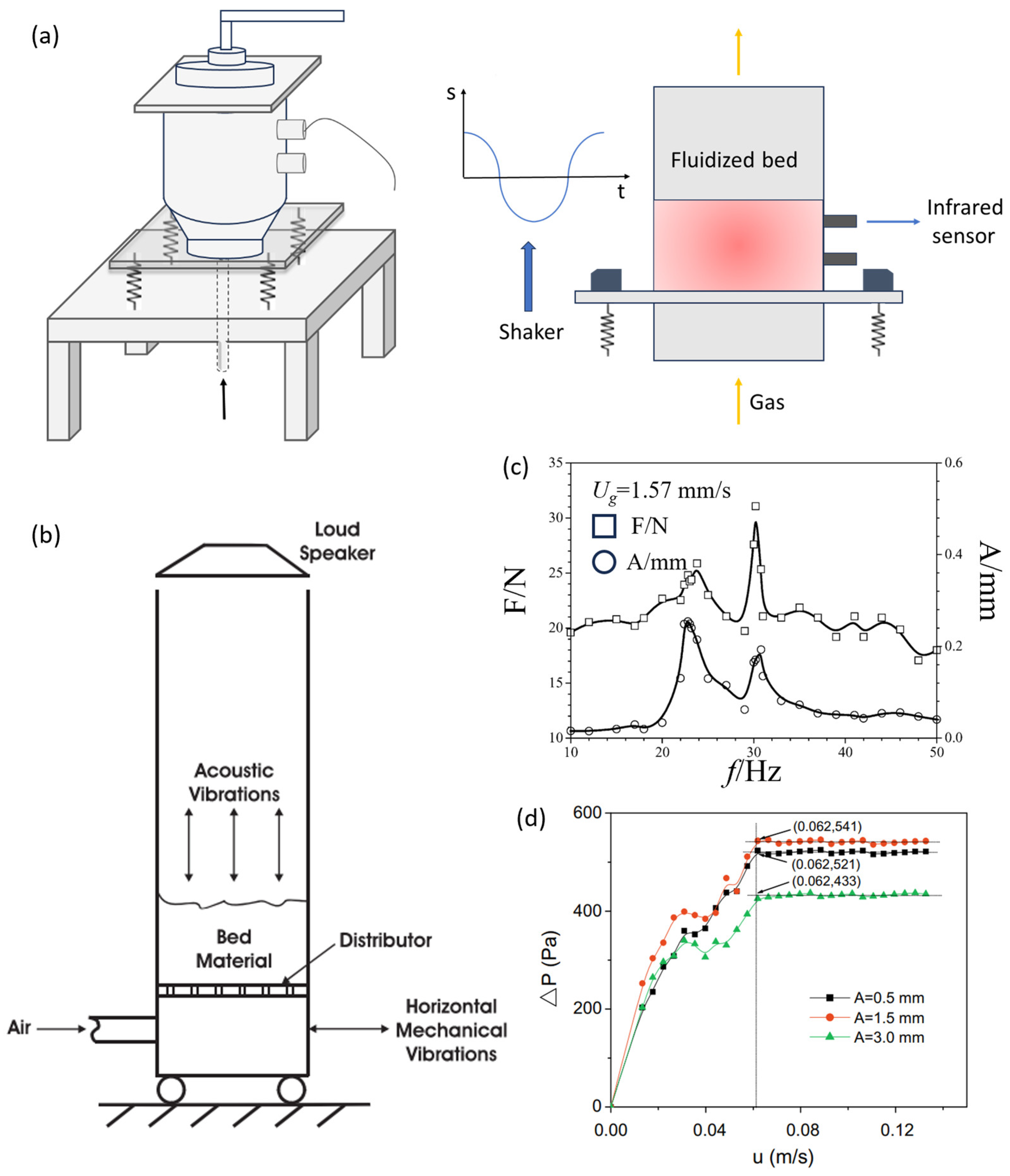
3.2.1. The Progress of Vibration Field-Assisted Micro-Nano Particle Fluidization

The technology of vibration field-assisted fluidization is called vibration fluidized bed (VFB) technology, and the VFB structure is shown in Figure 3a. By introducing mechanical vibration, a better fluidization quality can be obtained for micro-nano particles which are difficult to fluidize in the traditional fluidized bed. Particles are subjected to other mechanical forces besides gravity and drag force through VFB, to unravel the aggregates and ensure the fluidization quality. Previous studies on VFB have been relatively perfect, involving the effects of vibration frequency, vibration amplitude, vibration direction, and particle size on the minimum fluidization velocity, aggregate size, and bed porosity.
Mori et al. [66] were trailblazers in the field of vibration fluidization and successfully realized the stable fluidization of 10 μm activated carbon and Al2O3 at a low gas velocity. Valverde et al. [67] introduced a novel approach to estimating the size, density, and porosity of micro-nano particle hydrodynamic aggregates by combining the R-Z equation and the fractal structure of aggregates. Nam et al. [68] applied vertical sinusoidal vibration with an acceleration of up to 5.5 times gravity and frequencies ranging from 30 to 200 Hz to the fluidization of nano-silica. It was found that vertical sinusoidal vibration at this intensity and frequency can reduce the average aggregate size, increase bed expansion, and reduce the minimum fluidization velocity. Mawatari et al. [69] studied the effect of micro-nano particle size on VFB, and the results showed that the vibration improvement effect decreased with the increase of micro-nano particle size. In addition, quantitative conclusions are obtained. For particles with a size <20 μm, it has the effect of eliminating channeling.
The effect of vibration frequency on vibration fluidization is obvious. Levy and Celeste [63] studied the effect of vibration frequency on the fluidization of silica. By adding a horizontal vibration with a frequency of 9.5 Hz, the minimum fluidization velocity is reduced. Zhang and Zhao [70] also studied the horizontal vibration fluidization of three different silica nanoparticles with a vibration frequency <34 Hz. It is found that when the vibration frequency is >16.7 Hz, the three particles are fluidized smoothly, and the three particles cannot be fluidized after canceling the vibration. Barletta and Poletto [71] studied the effects of a 15–150 Hz vibration frequency on the compaction and maximum bed height of potato starch powder and silicon powder in a vibrating fluidized bed, respectively. The results showed that the compaction of potato starch powder increased when the vibration frequency was >45 Hz, while the compaction of silicon powder increased at all frequencies. Wang et al. [64] studied the effect of vibration frequency on the expansion of the bed. The results show that when the gas velocity is <2.1 mm/s, the vibration frequency of the fastest expansion of the bed to the peak is close to the resonance frequency of the fluidized bed. When the gas velocity is >2.1 mm/s, the vibration frequency of the fastest expansion of the bed to the peak is close to the resonance frequency of the vibration base. Yang et al. [65] studied the effect of the vibration frequency on the fluidization quality of three different nanoparticles. The results showed that the low vibration frequency had a compression effect on the bed and the improvement of the fluidization quality was not obvious. However, the high vibration frequency facilitated an increase in the bed pressure drop for all three nanoparticles, accompanied by a decrease in the minimum fluidization velocity, and some detailed results are shown in Figure 3d. Furthermore, they discovered that when the vibration frequency is low, a large gas velocity is needed to obtain a good fluidization effect, while when the vibration frequency is high, a small gas velocity can achieve a superior fluidization.
In summary, due to the effect of vibration on depolymerization, the vibration field with a certain vibration amplitude, frequency, and direction improves the fluidization quality of micro-nano particles. However, we can conclude that VFB technology has no limitations on particle types and can fluidize micro-nano particles within the vibration frequency range of 40 to 150 Hz [72]. In actual operation, the parameters such as vibration amplitude, frequency, and direction can be changed to adapt to the fluidization process of micro-nano particles with different sizes, types, and structures. The micro-nano particle aggregates are suppressed under the action of the vibration field, and the product quality is guaranteed.

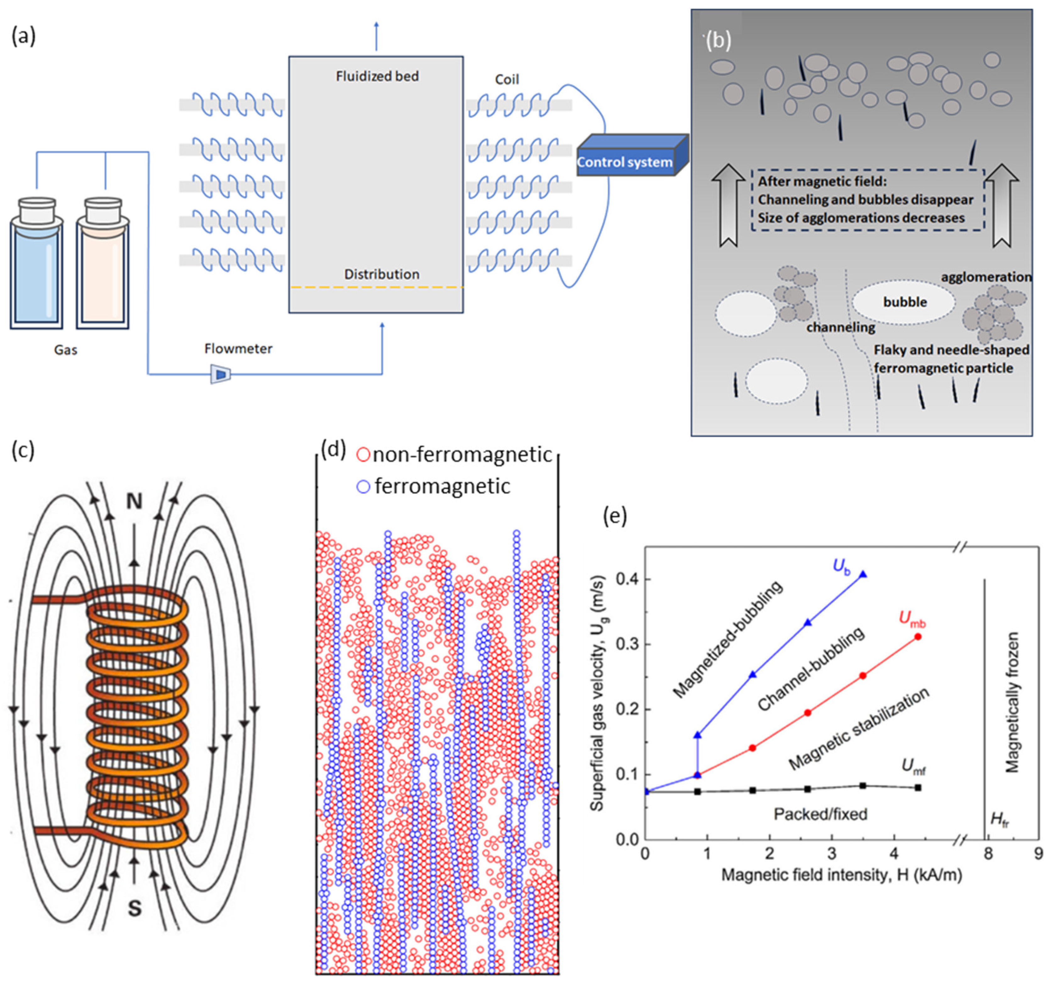
3.2.2. The Progress of Magnetic Field-Assisted Micro-Nano Particle Fluidization

Magnetic field-assisted fluidization is an interdisciplinary result of FB technology and electromagnetic technology. It is an efficient method to assist micro-nano particle fluidization. However, the use of a magnetic field is also limited to a large extent, as shown in Figure 4a. The flux linkage formed by the magnetic particles under the applied magnetic field can break the agglomerates, significantly reduce the minimum fluidization velocity, and eliminate the channeling and bubbles in the bed. The mechanism is detailed in Figure 4b and the flux linkage is detailed in Figure 4d. However, the way of applying a magnetic field depends on the magnetic induction particles, which not only increases the difficulty of the subsequent separation but also prevents the use of this method in reaction processes where magnetic induction particles cannot be added.
Similar to particle design-assisted fluidization, the earliest idea of magnetic field-assisted fluidization was put forward by Kwauk [37]. Diao et al. [76] investigated the effect of magnetic induction intensity and magnetic induction particle addition amount on the fluidization quality of nanoparticles. Using steel balls with a diameter of 2 mm and nano-SiO2 particles with an average particle size of 10 nm, it was found that under the action of the magnetic field, steel balls can break nano-SiO2 aggregates into smaller aggregates. Zhou et al. [77] evaluated the fluidization quality of a magnetic field fluidized bed by the minimum fluidization velocity and found that the addition of magnetic induction particles had a significant effect on the fluidization quality of micro-nano particles. Under the action of the magnetic field, the minimum fluidization velocity of SiO2, ZnO, and TiO2 powders decreased with the increase of the addition of magnetic induction particles. However, when the addition amount exceeds a certain value, the minimum fluidization velocity of the three micro-nano particles does not change. Yu et al. [78] conducted a comparative analysis of the pressure drop and bed expansion behavior of SiO2 nanoparticle aggregates in the presence and absence of a magnetic field. In the absence of a magnetic field, the movement of smaller aggregates at the top of the bed was observed, while the larger aggregates remained at the bottom of the bed, resulting in almost no expansion of the bed. After the introduction of an external magnetic field, due to the fragmentation caused by the collision between the aggregates and the magnetic induction particles, the size of the larger aggregates becomes smaller. The bed expands slowly and evenly, and the pressure drop becomes very close to the weight of the bed.
Lv and Li [79] have proved that not all micro-nano particles can make their fluidization quality improved by the magnetic field. For example, no matter what kind of magnetic induction particles added, CaCO3 exhibit piston phenomenon, and the fluidization of SiC and TiO2 particles has not been fundamentally improved. It is speculated that there is a matching relationship between the physical properties and the ratio of magnetic induction particles and micro-nano particles. Zhu and Li [80] first systematically studied the mechanism of magnetic field-assisted micro-nano particle fluidization and deeply analyzed the mechanism of the magnetic field fluidized bed from the force situation. It is considered that the breaking of bubbles in magnetic field fluidized beds is inevitable and not affected by particle size, and the magnetic induction particles form a needle-like structure along the direction of the magnetic field, which not only breaks the bubbles but also breaks the micro-nano particle aggregates. The mathematical model of fluidization quality and magnetic induction intensity is further constructed to facilitate the optimization of magnetic fluidized bed designs.
Magnetic field-assisted micro-nano particle fluidization technology is only effective for ferromagnetic particles or mixed particles with ferromagnetic particles, but not for non-ferromagnetic particles. It is generally believed that magnetic field-assisted micro-nano particle fluidization research can be divided into the direct study of magnetic micro-nano particle fluidization in a magnetic field and the improvement of micro-nano particle fluidization quality by adding magnetic induction particles. Regardless of the method used, micro-nano particle types are constrained compared to VFB technology. The force of micro-nano particles in the magnetic field fluidized bed is complex, and there is a lack of a general accurate force analysis formula. There are few simulation studies on magnetic field-assisted fluidization. At present, the advantages and disadvantages of magnetic field-assisted fluidization are prominent, and the research on magnetic field coupling with other external force fields remains to be developed.

3.2.3. The Progress of Sound Field-Assisted Micro-Nano Particle Fluidization

Compared with the magnetic field fluidized bed, the sound field fluidized bed has the advantage of not requiring a subsequent separation treatment. Because the movement of the fluidized bed in the actual industrial production is not conducive to the production activities, compared with the vibration field fluidized bed, the advantage of the sound field fluidized bed is that the fluidized bed does not need to move, and the sound field directly acts on the micro-nano particle. The schematic diagram of the sound field fluidized bed is shown in Figure 5a. The sound wave signal can be directly generated by the external signal generator without adversely affecting the fluidized bed device itself. The researchers mainly studied the effects of sound pressure, frequency, and particle type on the sound field fluidized bed. The research spans a long time and has various forms.
The study of sound field-assisted micro-nano particle fluidization was first carried out by Morse. In 1955, Morse [84] fluidized a variety of micro-nano particles of 1–10 μm with a sound pressure greater than 110 dB and a frequency of 50–100 Hz. The experimental results show that the presence or absence of a sound field has no significant effect on the fluidization quality of coarse particles. However, for fine particles, the fluidization quality is significantly improved with the assistance of a sound field. Raganati et al. [85] further explored the fluidization quality of fine activated carbon assisted by a sound field. It is found that the fluidization quality of fine activated carbon is better when the sound pressure is greater than 125 dB, and the fluidization quality is the best when the frequency is between 50–120 Hz. Sound pressure is an imperative operating factor in the sound field fluidized bed. Levy et al. [86] investigated the effect of different sound pressures on the fluidization of 40 μm micro-nano particles and found that when the sound pressure is lower than 100 dB, the bed height increases with the increase of sound pressure. When the sound pressure increases from 100 dB to 130 dB, the bed height decreases. Herrera and Levy [87] studied the effect of a particle size of 11–80 μm micro-nano particles on the sound pressure in the sound field fluidized bed. The results show that the high sound pressure can effectively reduce the adhesion force between micro-nano particles. With the increase of sound pressure, the minimum bubble velocity decreases and the bubble size increases.
In addition to sound pressure, frequency stands as another pivotal operational parameter in the sound field fluidized bed. Zhu et al. [83] used sound power to enhance the fluidization of SiO2 nanoparticles. By placing a loudspeaker at the top of the fluidized bed, a larger bed expansion rate and a lower minimum fluidization velocity were obtained at a frequency of 50 or 100 Hz, as shown in Figure 5b. Guo et al. [88] also fluidized SiO2 nanoparticles under the action of the sound field. At frequencies below 200 Hz, their experimental results are similar to those of Zhu et al. [83]. Liu et al. [89] carried out sound field-assisted fluidization of two kinds of SiO2 nanoparticles with different surface sizes of 5–10 nm, one modified with organic compounds, and the other without a surface modification. The sound field of 50–100 Hz reduces the minimum fluidization velocity of the two nanoparticles, but only the SiO2 nanoparticles treated by organic compounds can be fluidized smoothly. This indicates that the surface properties of particles in the sound field fluidized bed should also be paid attention to. Ammendola and Chirone [90] also studied the sound field-assisted fluidization of SiO2 and Al2O3 micro-nano particles. As previously mentioned, they found that the fluidization quality of the two micro-nano particles was poor without the assistance of a sound field. However, the sound field with a sound pressure exceeding 135 dB and a frequency of about 120 Hz improves the fluidization quality of the two micro-nano particles. Further research revealed a limitation of the sound field-assisted fluidization of the top speaker: it effectively impacted only the area proximate to the free surface.
Obviously, the key parameters of the sound field-assisted fluidization are sound pressure and frequency. The channeling of micro-nano particles has been suppressed at a sound pressure of 100 dB and higher. It is generally believed that a sound field with a wide frequency range from 20 to 1000 Hz and a sound pressure range from 100 to 115 dB can significantly improve the fluidization quality of micro-nano particles. Compared with other methods, the sound field has the advantages of being less affected by the physical properties of the particles themselves, not changing the main body of the fluidized bed, and not needing to subsequently separate the particles. It is a preferred method to reduce the size of aggregates, reduce particle entrainment, and assist micro-nano particle fluidization. However, in summary, it can be found that the sound field fluidized bed often places the speaker at the top or bottom of the fluidized bed. Due to the obvious attenuation during the sound wave transmission process, the fluidization quality away from the sound source is poor. Therefore, the development of sound field fluidized beds is limited by the development of sound field technology. In the future, the research on sound wave transmission and sound source placement should be strengthened.
In a word, the advantages and disadvantages of various external force field technologies are shown in Table 2, among which the research of the vibration field, magnetic field, and sound field is particularly prominent. Because it not only effectively inhibits the growth of bubbles and the occurrence of channeling, but also improves the production capacity of the fluidized bed, it has attracted the attention of many scholars based on the above advantages. By comprehensively considering incorporating the length of the review and the research popularity across the listed fields, we will not provide further details on other external force field-assisted micro-nano particle fluidization.

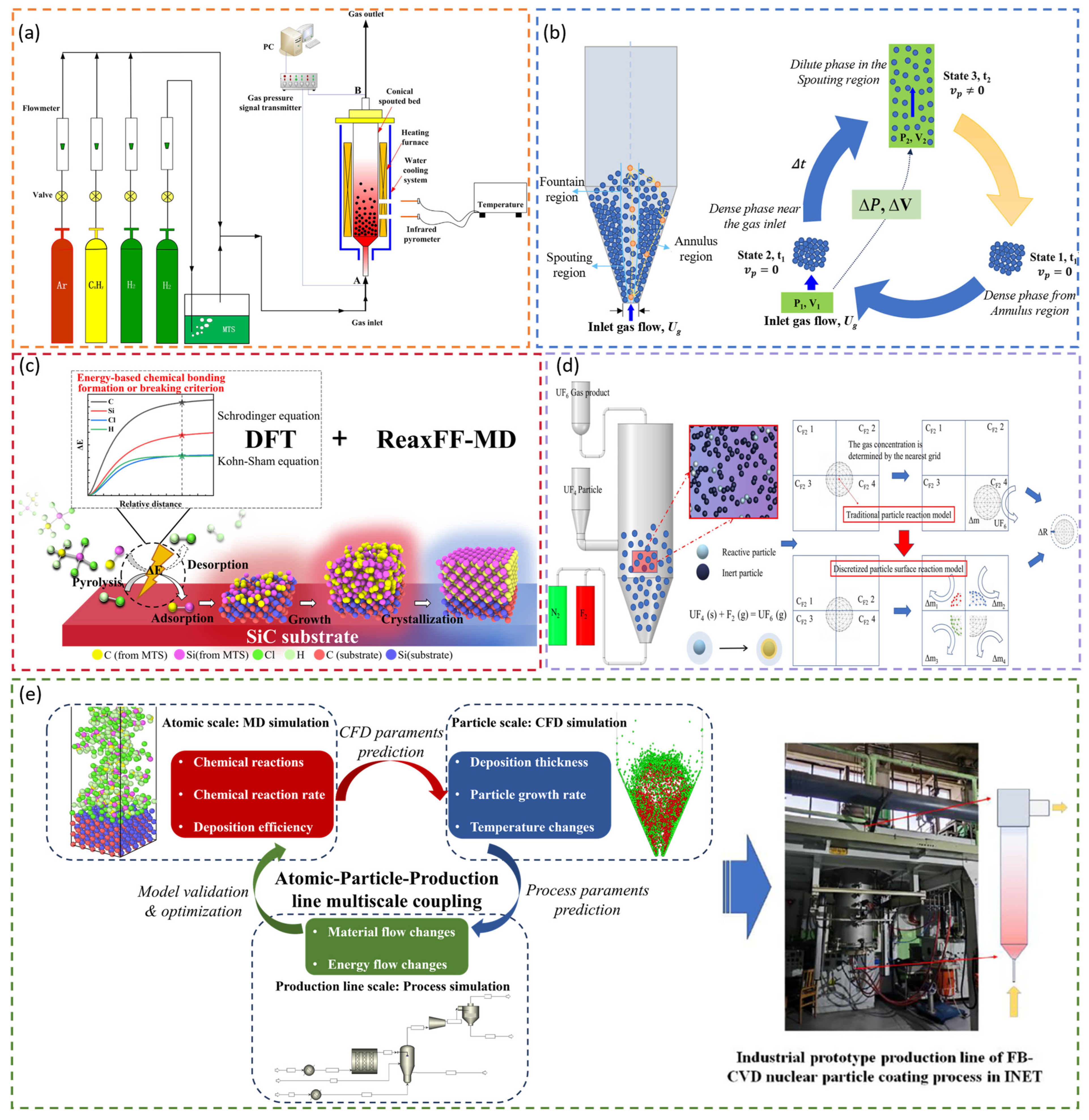
3.3. The Progress of Micro-Nano Particle CVD Coating

The coating modification of micro-nano particles can maintain its excellent performance while obtaining additional functions such as oxidation resistance and corrosion resistance. It is widely used in pharmaceutical, food, paint, and other industries. According to the type of interaction between the coating layer and the powder surface, the coating can be simply divided into the physical coating and chemical coating. According to the preparation method, the surface coating methods of micro-nano particles include the hydrothermal synthesis method [104], spray pyrolysis method [105], mechanochemical method [106], microencapsulation method [107], liquid phase deposition method [108], and vapor deposition method. Among them, the CVD method has received widespread attention due to its low equipment requirements and suitability for industrial production [109,110,111]. A part of the research status of micro-nano particle CVD coating technology is shown in Figure 6.
Tian et al. [117] used the porous silicon obtained by the oxalic acid etching of the AlSi alloy with an average particle size of 48 μm as the matrix and used FB-CVD technology to coat a uniform and compact carbon layer with acetylene as the gaseous precursor. The composites exhibit excellent initial coulombic efficiency and cycling stability as anodes for lithium-ion batteries. After 100 cycles at 0.5 A g−1, the composites exhibit a 83% capacity retention and a 1408 mAhg−1 reversible capacity. Shi et al. [116] also applied FB-CVD technology to the field of lithium batteries. Two different carbon layers were coated with SiO with a diameter of 5 μm, and the prepared SiO/1D-C/a-C composite had an ingenious double-coated layer structure with a capacity retention rate of 88.3% and a reversible capacity of 1012 mAhg−1 after 120 cycles. The experimental details are shown in Figure 6f. Wang and Obrovac [118] devised a small CVD device for micro-nano particle CVD technology, which is characterized by tilting the furnace and being able to rotate so that micro-nano particles can be concentrated in the reaction area to improve the yield. Al2O3 powder (600 mesh) and graphite powder (~26 μm) were coated with carbon by this device. The resultant product can be used as a lithium battery electrode to effectively inhibit the electrolyte reaction.
Choi et al. [119] coated 3–4 nm multilayer graphene on silver nanoparticles with a particle size of 95 nm by CVD technology, and retained the spherical shape of silver nanoparticles. The prepared monodisperse nanomaterials have a high thermal conductivity of 71 W/(m∙K) and an electrical resistivity of 6.0 × 10⁻⁸ Ω∙m, which has the potential to improve the thermal conductivity of thermal interface materials. Yang et al. [120] prepared carbon-coated nanoalloys with controllable magnetization by CVD technology. The electromagnetic wave attenuation ability can be significantly adjusted by coating nanoalloys. The optimized carbon-coated FeCoNiMg nanoalloy can broaden the absorption bandwidth from 10.4 GHz to 18.0 GHz at a thickness of 2.7 mm, and the reflection loss is 51.8 dB at a thickness of 2.9 mm. The coating structure can help develop a new type of lightweight and efficient electromagnetic wave absorber. Shin et al. [121] utilized CVD technology to convert polyvinylpyrrolidone precursors into multilayer graphene, which was deposited on the surface of nano-Cu to prevent the oxidation of nano-Cu and increase thermal conductivity. A thermogravimetric analysis revealed that the initial oxidation temperature is higher than the upper limit of the temperature of electronic components, so the multilayer graphene-coated nano-Cu can be used as a thermal interface material. Zhang et al. [122] prepared graphene-coated Au nanoparticles with particle sizes of 50 and 500 nm by CVD technology. The thickness of the graphene can be controlled from several layers to multiple layers. Due to the existence of a graphene shell, the nanoparticles have a good pH stability and a high temperature stability. This structure can be further effectively applied to catalytic reactions.
Undoubtedly, the research on the CVD coating of micro-nano particles has made relatively perfect progress, while the research on the FB-CVD coating of micro-nano particles still needs to be strengthened. FB-CVD technology needs to achieve representative results in micro-nano particle coating. It is necessary to deeply study the internal relationship between size and agglomeration, carry out new technologies and new methods for research in this field, closely link the advantages of FB-CVD technology with application scenarios, and make great progress.

4. The High-Tech Applications of FB-CVD Technology for Micro-Nano Particle Coatings

4.1. Advanced Nuclear Fuel

FB-CVD technology was first applied in the field of nuclear fuel to prepare the coated layer of coating fuel particles in a high temperature gas-cooled reactor. This particle is coated with a porous buffer pyrolysis carbon layer, an inner dense pyrolysis carbon layer, a silicon carbide (SiC) layer, and an outer dense pyrolysis carbon layer on a UO2 kernel, respectively. These four layers of coating are continuously produced by FB-CVD technology [123]. The porous buffer pyrolysis carbon layer is used to accommodate the fission gas. The inner dense pyrolysis carbon layer is used to block the gaseous and solid fission products and provide the deposition surface for SiC. The SiC layer is the main barrier fission product layer and the structural pressure-bearing layer. The outer dense pyrolysis carbon layer generates irradiation shrinkage to apply compressive stress to SiC. This particle, it should be noted, has already achieved industrial application in China. Based on this design, the author’s research group has improved it by replacing the porous buffer pyrolysis carbon layer with a porous SiC inner layer, which avoids the reaction between C and UO2 under high temperature conditions [124]. FB-CVD technology is also used to prepare ZrC, Zr, Nb, and other new coating layers [125,126]. Furthermore, simulation calculations explained the deposition mechanism of SiC and optimized the process parameters [127,128]. A part of the research work of the author’s research group applying FB-CVD technology to the field of advanced nuclear fuel is shown in Figure 7.
FB-CVD technology is also applied to improve the nuclear fuel sintering compatibility. The new dispersion fuel of uranium–molybdenum alloy (UMo) powder has been identified as the nuclear fuel of a specific reactor. However, due to its poor sintering compatibility, the surface modification of UMo powder is needed. With the help of FB-CVD technology, Vanni et al. [27] used metal tungsten particles (75 μm, 19,300 kg/m3) instead of UMo powder as the core in the experiment, and used SiH4 as the gaseous precursor at 645 °C, and obtained uniform and continuous crystalline and nodular silicon films with a thickness of 0.1–1 μm. The problem of the poor sintering compatibility of UMo powder was solved by FB-CVD micro-nano particle coating technology.

4.2. Electrode Materials for Battery

The capacity of a traditional graphite anode is only 372 mAhg−1, while the capacity of a silicon anode is 4200 mAhg−1, which is far more than 10 times that of a traditional graphite anode. However, due to the volume expansion of the silicon anode during lithiation and delithiation processes, the silicon anode has not been widely used. The use of FB-CVD technology to nanostructure and prepare composite materials can effectively solve this problem, so FB-CVD technology is widely used in the efficient preparation of high-performance electrode materials.
Shi et al. [132] proposed a method using carbon nanotubes (CNT) for an in-situ synthesis of high-performance (SiO + G)/CNTs electrode materials by FB-CVD technology. With the concept of particle design as the core, commercial graphite was mixed with commercial SiO (5 μm). By decreasing bonding among SiO particles, the presence of graphite improves the fluidization quality and inhibits the agglomerate growth of SiO particles. Moreover, the (SiO + G)/CNTs high-performance electrode material synthesized by FB-CVD technology can provide a high stable reversible capacity of 466 mAhg−1 after 125 cycles. Further studies have found that the (SiO + G)/CNTs composite materials prepared by FB-CVD technology not only buffer the volume expansion and contraction effects during silicon lithiation and delithiation processes, but also ensure an excellent structural stability and conductivity, and successfully improve the electrochemical performance of the electrode.
Based on the analysis and regulation of the stability of the gas–solid phase structure of the fluidized bed, Xiao et al. [133] reported the production of high-performance silicon–oxygen–carbon electrode materials by FB-CVD technology in the 100 kg scale. The problem of conductivity and volume expansion was solved by coating a carbon layer on the surface of the SiOX powder with a particle size of 3.3 μm. Starting from the derivation of the van der Waals equation, a hundred-micron secondary particles are constructed to achieve a stable fluidization, and a layered growth and uniform carbon coating layer is obtained. By designing a secondary particle, agglomeration was suppressed and the heat/mass transfer efficiency was improved. The product has a capacity of 1014 mAhg−1 after 500 cycles of the charge and discharge at 1 C. Shi et al. [134] focused on the morphology and growth mechanism of the TiN coating layer. SiO@TiN and SiO@CNTs@TiN composite materials with a thin film coating layer were prepared by FB-CVD technology at 900 °C. After 100 cycles at a current density of 0.1 A g−1, the former discharge specific capacity is 1214.1 mAhg−1, and the latter discharge specific capacity is 1310.1 mAhg−1. The high performance of these two materials is attributed to the TiN coating prepared via FB-CVD technology, which isolates the contact between the electrolyte and SiO and avoids the occurrence of side reactions.

4.3. Semiconductor Materials

Silicon carbide (SiC) was used early on for rectification and detection. The advent of elemental semiconductor silicon has ushered in the era of large-scale integrated circuits. FB-CVD technology is particularly prominent in the preparation of SiC and polycrystalline silicon, with the advantages of high purity and high yield. The SiC material has a good chemical stability and a high mechanical strength and can be used in harsh environments such as high temperatures, irradiation, and corrosion. However, the sintering of bulk SiC requires high temperature and pressure conditions. The author’s research group skillfully uses FB-CVD technology to controllably prepare SiC@Graphene core–shell nanoparticles with an average particle size of 10 nm by the fine regulation of temperature, in which the thickness of graphene is 1–5 layers and the mass fraction is 5.89–11.88%. Hexamethyldisilane was used as a gaseous precursor in this experiment. After being heated to 80 °C in a water bath, it was introduced into a fluidized bed to decompose into SiC nanoparticles, and then decomposed into C and coated on the surface of SiC to form core–shell nanoparticles [135]. The author’s research group also used methyltrichlorosilane (CH3Cl3Si) as a gaseous precursor and ZrO2/CoO as a catalyst to prepare SiC nanowires with a diameter of 10–50 nm and a length greater than several hundred micrometers with an ultra-high aspect ratio by FB-CVD technology at 1600 °C. Furthermore, the continuous preparation of SiC nanowires was realized by product collection devices and continuous gas carriers, which has the prospect of industrial application [26].
The deposition reaction of CH3Cl3Si to SiC can be expressed as follows:
CH3Cl3Si (gas) → SiC (solid) + 3HCl (gas)
The traditional production methods of polysilicon materials widely used in microelectronics and photovoltaic industries have a high energy consumption and high pollution. FB-CVD technology is considered to be the most promising alternative technology [136]. Cadoret et al. [137] used SiH4 as a gaseous precursor to coat submicron TiO2 single particles with nano-scale silicon in a vibrating fluidized bed. The optimal operating parameters for the initial powder compaction state, distribution porosity, initial bed weight, initial gas velocity, and vibration direction were determined. Due to the presence of the vibration field, the force exerted on the micro-nano particles increases and tends to damage the aggregates. The experimental results show that 90% of the particles are uniformly deposited with nano-silicon in the original particle size, except for about 10% of the particles agglomerated near the distributor. Furusawa et al. [138] tested the pyrolysis rate of SiH4 in the temperature range of 550–700 °C with or without small grain polysilicon silicon species, to evaluate the homogeneous and heterogeneous reaction rate, and explained the phenomenon of fine powder formation in previous reports. In the 1990s, after the computational fluid dynamics (CFD) method was widely used in FB-CVD research, the CFD method was also applied to the study of polycrystalline silicon deposition by FB-CVD technology. Reuge et al. [139] used the CFD method to perform a transient modeling of SiH4 to Si by FB-CVD technology. The three-dimensional simulation results show that the interaction among fluid mechanics, heat transfer, and mass transfer is obvious, and the deposition of SiH4 mainly occurs in the dense phase region of the bed. Cadoret et al. [140] applied the CFD to the transient simulation of SiH4 to Si by FB-CVD technology. Compared with the experimental values, the average deviation of the predicted SiH4 conversion rate was 9%. The variation of local porosity, gas velocity, and Si deposition rate with time can also be predicted.
The deposition reaction of SiH4 to Si can be expressed as follows:
SiH4 (gas) → Si (solid) + 2H2 (gas)

5. Future Prospectives

Future research endeavors should prioritize the following directions, fundamental mechanisms of single-particle fluidization (e.g., investigate the kinetic behavior and interfacial interactions of individual micro-nano particles during fluidization and CVD), the multiscale modeling of coupled transport-reaction processes (e.g., develop integrated computational frameworks combining discrete element methods (DEM), CFD, and reactive molecular dynamics (ReaxFF) to simulate mass–momentum–energy coupling, precursor decomposition, and film growth), multiphysics field coupling for fluidization optimization (e.g., pulsed vibration with modulated magnetic fields), sustainable process design and resource efficiency (e.g., investigate closed-loop systems for precursor recovery and byproduct recycling,), real-time process monitoring and adaptive control (e.g., integrate multisensor arrays with AI-driven feedback systems to enable dynamic adjustment of gas flow, temperature, and field intensity), and cross-disciplinary functional coating systems for energy and biomedicine (e.g., cross-disciplinary collaborations with computational science and biotechnology).
It is noteworthy that FB-CVD micro-nano particle coating technology has developed from being completely unable to fluidize to agglomerate fluidization, but the single particle fluidization coating of micro-nano particles needs to be further studied in many aspects:
Firstly, the theoretical analysis of micro-nano particle fluidization coating is not clear enough; secondly, the modeling and simulation calculation of micro-nano particle fluidization coating at this stage cannot fully reflect the real situation; thirdly, it is urgent to study the black box process in FB-CVD technology, including but not limited to real-time detection and analysis methods such as high-speed camera, thermal measurement, and pressure measurement.
At present, FB-CVD coating technology does not have a perfect theoretical system. To establish a perfect theoretical system, the theoretical basis of the mass, momentum, and energy coupling/transfer mechanism should be established from the principles of fluid mechanics, chemical reaction kinetics, and thermodynamic mechanisms. Through extensive experimental data and rigorous theoretical analysis results, we can better understand the chemical reaction and film growth process, and promote a deep understanding of the role of FB in CVD. On this basis, we can explore the evolution rules and key regulatory factors in the FB-CVD process, and further realize the process amplification and optimization.

6. Conclusions

FB-CVD technology is a new interdisciplinary technology with broad development prospects. This review comprehensively examines the advancements and challenges of FB-CVD technology in coating micro-nano particles. By integrating the high heat/mass transfer efficiency of fluidized beds with the precision of CVD, FB-CVD offers a superior uniformity, cost-effectiveness, and scalability compared to conventional CVD. The mechanisms of particle fluidization and CVD are systematically analyzed, highlighting the persistent challenge of micro-nano particle agglomeration due to van der Waals forces, electrostatic interactions, and surface energy effects. The recent progress in process intensification—such as particle design (e.g., core–shell aggregates, and adding second components) and external field assistance (e.g., vibration, magnetic, and sound fields)—has significantly enhanced the fluidization stability and coating homogeneity. Applications in advanced nuclear fuel, electrode materials for batteries, and semiconductor materials underscore the technology’s versatility. However, gaps remain in understanding single-particle dynamics, multi-physics coupling models, and industrial scalability. Addressing these limitations is critical for advancing FB-CVD from laboratory-scale innovations to large-scale manufacturing.
The practical challenges of FB-CVD technology applied to coated micro-nano particles remain an unresolved issue. Some of the problems are caused by the special properties of micro-nano particles, but most of the problems are also common problems in the field of FB-CVD, which deserve more attention. It is necessary to further study the agglomeration mechanism of micro-nano particles, and explore new measures and methods to solve the agglomeration problem from the mechanism. In addition to the experimental method, simulation calculation is also an important means to study the FB-CVD micro-nano particle coating technology. Because of the multi-field coupling characteristics of FB-CVD technology (mass–momentum–energy transfer + chemical reaction), its numerical modeling is a major problem in simulation calculation. Some models are only applicable to specific situations, and the universality is poor. Achieving universal quantitative calculation and model prediction still necessitates extensive experimental endeavors and rigorous theoretical analysis.
With the continuous development of FB-CVD technology, the application of coated micro-nano particles will be more and more extensive. Today, there are few studies on FB-CVD micro-nano particle coating; however, it is believed that there will be a broader development prospect in the future as more attention is paid to this field.

Author Contributions

Conceptualization, B.L. (Bowen Li) and M.L.; methodology, R.L., X.Y. and Y.S.; validation, B.L. (Bowen Li), Z.X. and G.D.; writing—original draft preparation, B.L. (Bowen Li); writing—review and editing, M.L. and R.L.; supervision, B.L. (Bing Liu); funding acquisition, R.L. All authors have read and agreed to the published version of the manuscript.

Funding

This research was funded by the National Natural Science Foundation of China (Nos. 52272066).

Institutional Review Board Statement

Not applicable.

Informed Consent Statement

Not applicable.

Data Availability Statement

Not applicable.

Conflicts of Interest

The authors declare no conflicts of interest.

References

  1. Knowlton, T.M.; Keairns, D.L.; Yang, W.C. History of Fluidization in North America. Powder Technol. 2023, 426, 118609. [Google Scholar] [CrossRef]
  2. Philippe, R.; Morançais, A.; Corrias, M.; Caussat, B.; Kihn, Y.; Kalck, P.; Plee, D.; Gaillard, P.; Bernard, D.; Serp, P. Catalytic Production of Carbon Nanotubes by Fluidized-Bed CVD. Chem. Vap. Depos. 2007, 13, 447–457. [Google Scholar] [CrossRef]
  3. Liu, S.; Xiao, W. Numerical Simulations of Particle Growth in a Silicon-CVD Fluidized Bed Reactor via a CFD-PBM Coupled Model. Chem. Eng. Sci. 2014, 111, 112–125. [Google Scholar] [CrossRef]
  4. Li, J.; Chen, G.; Zhang, P.; Wang, W.; Duan, J. Technical Challenges and Progress in Fluidized Bed Chemical Vapor Deposition of Polysilicon. Chin. J. Chem. Eng. 2011, 19, 747–753. [Google Scholar] [CrossRef]
  5. Vahlas, C.; Caussat, B.; Serp, P.; Angelopoulos, G.N. Principles and Applications of CVD Powder Technology. Mater. Sci. Eng. R-Rep. 2006, 53, 1–72. [Google Scholar] [CrossRef]
  6. Sharma, S.; Kalita, G.; Hirano, R.; Shinde, S.M.; Papon, R.; Ohtani, H.; Tanemura, M. Synthesis of Graphene Crystals from Solid Waste Plastic by Chemical Vapor Deposition. Carbon 2014, 72, 66–73. [Google Scholar] [CrossRef]
  7. Goto, T. A Review: Structural Oxide Coatings by Laser Chemical Vapor Deposition. J. Wuhan Univ. Technol.-Mater. Sci. Ed. 2016, 31, 1–5. [Google Scholar] [CrossRef]
  8. Chhowalla, M.; Teo, K.B.K.; Ducati, C.; Rupesinghe, N.L.; Amaratunga, G.A.J.; Ferrari, A.C.; Roy, D.; Robertson, J.; Milne, W.I. Growth Process Conditions of Vertically Aligned Carbon Nanotubes Using Plasma Enhanced Chemical Vapor Deposition. J. Appl. Phys. 2001, 90, 5308–5317. [Google Scholar] [CrossRef]
  9. Tan, S.T.; Chen, B.J.; Sun, X.W.; Fan, W.J.; Kwok, H.S.; Zhang, X.H.; Chua, S.J. Blueshift of Optical Band Gap in ZnO Thin Films Grown by Metal-Organic Chemical-Vapor Deposition. J. Appl. Phys. 2005, 98, 013505. [Google Scholar] [CrossRef]
  10. Ma, L.; Chen, A.; Lu, J.; Zhang, Z.; He, H.; Li, C. In Situ Synthesis of CNTs/Fe-Ni/TiO2 Nanocomposite by Fluidized Bed Chemical Vapor Deposition and the Synergistic Effect in Photocatalysis. Particuology 2014, 14, 24–32. [Google Scholar] [CrossRef]
  11. Aslam, S.; Sekkat, A.; Vergnes, H.; Esvan, J.; Pugliara, A.; Samelor, D.; Eshraghi, N.; Vahlas, C.; Auvergniot, J.; Caussat, B. A New Route to Apply Nanometric Alumina Coating on Powders by Fluidized Bed Chemical Vapor Deposition. Chem. Eng. J. Adv. 2023, 16, 100554. [Google Scholar] [CrossRef]
  12. Liu, R.; Zhao, J.; Yang, X.; Liu, M.; Chang, J.; Shao, Y.; Liu, B. Mass Production of 3D Connective Graphene Networks by Fluidized Bed Chemical Vapor Deposition and Its Application in High Performance Lithium-Sulfur Battery. Nanomaterials 2022, 12, 150. [Google Scholar] [CrossRef] [PubMed]
  13. Yang, H.; Zhou, P.; Zhao, H.; Li, Z.; Liu, X.; Zhang, K.; Liu, B. SiC Coating on HTR Graphite Spheres Prepared by Fluidized-Bed Chemical Vapor Deposition. Ann. Nucl. Energy 2019, 134, 11–19. [Google Scholar] [CrossRef]
  14. Arrieta, M.Y.; Keiser, D.D.; Perez-Nunez, D.; McDeavitt, S.M. Fluidized Bed Chemical Vapor Deposition of Zirconium Nitride Films. Nucl. Technol. 2017, 199, 219–226. [Google Scholar] [CrossRef]
  15. Sudderth, L.; Perez-Nunez, D.; Keiser, D.; McDeavitt, S. Fabrication of ZrN Barrier Coatings for U-Mo Microspheres Via Fluidized Bed Chemical Vapor Deposition Using a Metalorganic Precursor. Nucl. Technol. 2018, 202, 81–93. [Google Scholar] [CrossRef]
  16. Ha, J.; Do, Y.; Park, J.; Han, C. Preparation and Photocatalytic Performance of Nano Titania-Coated Beads. In Eco-Materials Processing and Design X; Kim, H., Yang, J.F., Sekino, T., Lee, S.W., Eds.; Trans Tech Publications Ltd.: Zurich, Switzerland, 2009; Volume 620–622, pp. 663–666. [Google Scholar]
  17. Zhou, J.; Chizhik, A.I.; Chu, S.; Jin, D. Single-Particle Spectroscopy for Functional Nanomaterials. Nature 2020, 579, 41–50. [Google Scholar] [CrossRef]
  18. Gupta, P.; Jani, K.A.; Yang, D.; Sadoqi, M.; Squillante, E.; Chen, Z. Revisiting the Role of Nanoparticles as Modulators of Drug Resistance and Metabolism in Cancer. Expert Opin. Drug Metab. Toxicol. 2016, 12, 281–289. [Google Scholar] [CrossRef]
  19. Magasinski, A.; Dixon, P.; Hertzberg, B.; Kvit, A.; Ayala, J.; Yushin, G. High-Performance Lithium-Ion Anodes Using a Hierarchical Bottom-up Approach (Vol 9, Pg 353, 2010). Nat. Mater. 2010, 9, 461. [Google Scholar] [CrossRef]
  20. Mondal, A.; Arora, M.; Dubey, B.K.; Mumford, K. Comparative Assessment of the Characteristics and Cr(VI) Removal Activity of the Bimetallic Fe/Cu Nanoparticles Pre- and Post-Coated with Carboxymethyl Cellulose. Chem. Eng. J. 2022, 444, 136343. [Google Scholar] [CrossRef]
  21. Ramakrishnan, V.M.; Pitchaiya, S.; Muthukumarasamy, N.; Kvamme, K.; Rajesh, G.; Agilan, S.; Pugazhendhi, A.; Velauthapillai, D. Performance of TiO2 Nanoparticles Synthesized by Microwave and Solvothermal Methods as Photoanode in Dye-Sensitized Solar Cells (DSSC). Int. J. Hydrogen Energy 2020, 45, 27036–27046. [Google Scholar] [CrossRef]
  22. Li, Z.; Li, J.; Liu, X.; Chen, R. Progress in Enhanced Fluidization Process for Particle Coating via Atomic Layer Deposition. Chem. Eng. Process.-Process Intensif. 2021, 159, 108234. [Google Scholar] [CrossRef]
  23. Liu, M.; Liu, R.; Liu, B.; Shao, Y. Preparation of the Coated Nuclear Fuel Particle Using the Fluidized Bed-Chemical Vapor Deposition (FB-CVD) Method. Procedia Eng. 2015, 102, 1890–1895. [Google Scholar] [CrossRef]
  24. Lassegue, P.; Noe, L.; Monthioux, M.; Caussat, B. Iron Deposition on Multi-Walled Carbon Nanotubes by Fluidized Bed MOCVD for Aeronautic Applications. Phys. Status Solidi 2015, 12, 861–868. [Google Scholar] [CrossRef]
  25. Balaji, S.; Du, J.; White, C.M.; Ydstie, B.E. Multi-Scale Modeling and Control of Fluidized Beds for the Production of Solar Grade Silicon. Powder Technol. 2010, 199, 23–31. [Google Scholar] [CrossRef]
  26. Liu, R.; Liu, M.; Chang, J.; Shao, Y.; Liu, B. Preparation of Highly Flexible SiC Nanowires by Fluidized Bed Chemical Vapor Deposition. Chem. Vap. Depos. 2015, 21, 196–203. [Google Scholar] [CrossRef]
  27. Vanni, F.; Caussat, B.; Ablitzer, C.; Iltis, X.; Bothier, M. Silicon Coating on Very Dense Tungsten Particles by Fluidized Bed CVD for Nuclear Application. Phys. Status Solidi-Appl. Mater. Sci. 2015, 212, 1599–1606. [Google Scholar] [CrossRef]
  28. Dosta, M.; Hoffmann, R.; Schneider, P.; Maus, M. Hybrid Models to Support Development of Fluid Bed Granulation Processes. Powder Technol. 2024, 444, 120005. [Google Scholar] [CrossRef]
  29. Wang, Q.; Zhou, T.; Li, Z.; Ding, Y.; Song, Q.; Zhang, M.; Hu, N.; Yang, H. Experimental Study on Preparation of Inorganic Fibers from Circulating Fluidized Bed Boilers Ash. Materials 2024, 17, 3800. [Google Scholar] [CrossRef]
  30. Yousuff, M.; Page, N.W. Particle Material, Morphology and Load Effects on Internal Friction in Powders. Powder Technol. 1993, 76, 155–164. [Google Scholar] [CrossRef]
  31. Zegzulka, J. The Angle of Internal Friction as a Measure of Work Loss in Granular Material Flow. Powder Technol. 2013, 233, 347–353. [Google Scholar] [CrossRef]
  32. Azad, M.; Moreno, J.; Bilgili, E.; Dave, R. Fast Dissolution of Poorly Water Soluble Drugs from Fluidized Bed Coated Nanocomposites: Impact of Carrier Size. Int. J. Pharm. 2016, 513, 319–331. [Google Scholar] [CrossRef] [PubMed]
  33. Yang, J.; Zhang, J.; Liu, J.; Yang, Q.; Wu, B.; Xu, X.; Huang, T. Recovery of Sb(III) from Aqueous Solution as Cubic Sb2O3 by Fluidized-Bed Granulation Process. Water 2024, 16, 1690. [Google Scholar] [CrossRef]
  34. Gänsch, J.; Huskova, N.; Kerst, K.; Temmel, E.; Lorenz, H.; Mangold, M.; Janiga, G.; Seidel-Morgenstern, A. Continuous Enantioselective Crystallization of Chiral Compounds in Coupled Fluidized Beds. Chem. Eng. J. 2021, 422, 129627. [Google Scholar] [CrossRef]
  35. Lu, B.; Zhang, J.; Luo, H.; Wang, W.; Li, H.; Ye, M.; Liu, Z.; Li, J. Numerical Simulation of Scale-up Effects of Methanol-to-Olefins Fluidized Bed Reactors. Chem. Eng. Sci. 2017, 171, 244–255. [Google Scholar] [CrossRef]
  36. Verma, A. Advance Coal-Fired Power-Generation Processes Part II. Energy Sources 1980, 5, 259–289. [Google Scholar] [CrossRef]
  37. Kwauk, M.; Li, J.; Liu, D. Particulate and Aggregative Fluidization—50 Years in Retrospect. Powder Technol. 2000, 111, 3–18. [Google Scholar] [CrossRef]
  38. Amontree, J.; Yan, X.; DiMarco, C.S.; Levesque, P.L.; Adel, T.; Pack, J.; Holbrook, M.; Cupo, C.; Wang, Z.; Sun, D.; et al. Reproducible Graphene Synthesis by Oxygen-Free Chemical Vapour Deposition. Nature 2024, 630, 636–642. [Google Scholar] [CrossRef]
  39. Hwang, N.M. Growth Mechanism of CVD Silicon. In Non-Classical Crystallization of Thin Films and Nanostructures in CVD and PVD Processes; Springer Series in Surface Sciences; Springer: Dordrecht, The Netherlands, 2016; Volume 60, pp. 163–180. ISBN 978-94-017-7616-5. [Google Scholar]
  40. Zhang, Y. Advances in Thermal Modeling of Laser Chemical Vapor Deposition and Infiltration; Evgova, J., Kostadinov, O., Eds.; Mechanical Engineering Theory and Applications; Nova Science Publishers, Inc: Hauppauge, NY, USA, 2010; pp. 283–316. ISBN 978-1-60741-497-1. [Google Scholar]
  41. Li, W.; Lu, Y. The Study of Friction and Wear Capability of Piston Ring Coatings. In Sae-China Congress 2016: Selected Papers; Springer-Verlag Singapore Pte Ltd.: Singapore, 2017; Volume 418, pp. 241–247. [Google Scholar]
  42. Lee, S.H.; Lee, G.H.; Lee, H.-S.; Kim, D.; Kang, Y. Characterization of MOCVD-Prepared CIS Solar Cells. Energies 2021, 14, 7721. [Google Scholar] [CrossRef]
  43. Zhang, L.; Xin, F.; Li, S.; Yang, Y.; Zhu, Q.; Wang, G. Enabling the Low-Cost Preparation of Core-Shell WC-Ni Powder by Developing a Non-Noble Metal-Based Catalytic. J. Am. Ceram. Soc. 2019, 102, 4492–4501. [Google Scholar] [CrossRef]
  44. Huang, J.; Militzer, C.; Xu, J.; Wijayawardhana, C.A.; Forsberg, U.; Pedersen, H. Growth of Silicon Carbide Multilayers with Varying Preferred Growth Orientation. Surf. Coat. Technol. 2022, 447, 128853. [Google Scholar] [CrossRef]
  45. Si, W.; Wang, N.; Zong, Y.; Dai, G.; Meng, F.; Yang, Z.; Zhao, L.; Xin, Z.; Jiang, G. A Revisit from CVD Kinetics to CVD Reactor: Investigating Uniform Growth Mechanism of Polysilicon in a Reduction Furnace. Chem. Eng. Sci. 2024, 295, 120162. [Google Scholar] [CrossRef]
  46. Xie, C.; Li, Y.; Xu, C.; Wang, Y.; Cong, H.; Xue, C. Epitaxial Growth of High-Quality Ge Layers on Si with Ge2H6 under UHV-CVD Conditions. Semicond. Sci. Technol. 2024, 39, 015008. [Google Scholar] [CrossRef]
  47. Musa, N.; Wong, T.W. Design of Polysaccharidic Nano-in-Micro Soft Agglomerates as Primary Oral Drug Delivery Vehicle for Colon-Specific Targeting. Carbohydr. Polym. 2020, 247, 116673. [Google Scholar] [CrossRef]
  48. Hu, D.; Zhuang, J.; Ding, M. A Review of Studies on the Granular Agglomeration Mechanisms and Anti-Agglomeration Methods. In Progress in Polymer Processing; Zhang, C., Ed.; Trans Tech Publications Ltd.: Zurich, Switzerland, 2012; Volume 501, pp. 515–519. [Google Scholar]
  49. Mao, D.; Edwards, J.R.; Kuznetsov, A.V.; Srivastava, R. A Model for Fine Particle Agglomeration in Circulating Fluidized Bed Absorbers. Heat Mass Transf. 2002, 38, 379–388. [Google Scholar] [CrossRef]
  50. Pacek, A.; Nienow, A. Fluidization of Fine and Very Dense Hard-Metal Powders. Powder Technol. 1990, 60, 145–158. [Google Scholar] [CrossRef]
  51. Hessels, C.J.M.; Lelivelt, D.W.J.; Stevens, N.C.; Tang, Y.; Deen, N.G.; Finotello, G. Minimum Fluidization Velocity and Reduction Behavior of Combusted Iron Powder in a Fluidized Bed. Fuel 2023, 342, 127710. [Google Scholar] [CrossRef]
  52. Geldart, D. Types of Gas Fluidization. Powder Technol. 1973, 7, 285–292. [Google Scholar] [CrossRef]
  53. Saleh, K.; Cami, X.B.; Thomas, A.; Guigon, P. An Experimental Study on the Fluidisation Behaviour of Geldart C Glass Powders. Kona Powder Part. J. 2006, 24, 134–145. [Google Scholar] [CrossRef]
  54. Xue, X.; Zhang, X.; Li, D.; Li, J.; Zhu, Q.; Li, H. SiO2 Microsphere-Assisted Reduction of Ultrafine CuO Powder in a Fluidized Bed. Chem. Eng. Sci. 2023, 269, 118500. [Google Scholar] [CrossRef]
  55. Zhou, Y.; Zhu, J. Group C+ Particles: Enhanced Flow and Fluidization of Fine Powders with Nano-Modulation. Chem. Eng. Sci. 2019, 207, 653–662. [Google Scholar] [CrossRef]
  56. Li, H.; Legros, R.; Brereton, C.; Grace, J.; Chaouki, J. Hydrodynamic Behavior of Aerogel Powders in High-Velocity Fluidized-Beds. Powder Technol. 1990, 60, 121–129. [Google Scholar] [CrossRef]
  57. Lauga, C.; Chaouki, J.; Klvana, D.; Chavarie, C. Improvement of the Fluidisability of Ni/Sio2 Aerogels by Reducing Interparticle Forces. Powder Technol. 1991, 65, 461–468. [Google Scholar] [CrossRef]
  58. Wang, J.; Xu, B.; Zhou, T.; Liang, X. Agglomeration Mechanism of Nanoparticles by Adding Coarse Fluid Catalytic Cracking Particles. Chem. Eng. Technol. 2016, 39, 1490–1496. [Google Scholar] [CrossRef]
  59. Duan, H.; Liang, X.; Zhou, T.; Wang, J.; Tang, W. Fluidization of Mixed SiO2 and ZnO Nanoparticles by Adding Coarse Particles. Powder Technol. 2014, 267, 315–321. [Google Scholar] [CrossRef]
  60. Kono, H.; Huang, C.; Morimoto, E.; Nakayama, T.; Hikosaka, T. Segregation and Agglomeration of Type-C Powders from Homogeneously Aerated Type-a-C Powder Mixtures During Fluidization. Powder Technol. 1987, 53, 163–168. [Google Scholar] [CrossRef]
  61. Scuzzarella, A.; Fernandez Bertos, M.; Simons, S.J.; Hills, C.D.; Carey, P.J. Expansion of Cohesive Gas Fluidized Binary Solid Systems. Powder Technol. 2006, 163, 18–22. [Google Scholar] [CrossRef]
  62. Zhou, T.; Li, H.Z. Effects of Adding Different Size Particles on Fluidization of Cohesive Particles. Powder Technol. 1999, 102, 215–220. [Google Scholar] [CrossRef]
  63. Levy, E.K.; Celeste, B. Combined Effects of Mechanical and Acoustic Vibrations on Fluidization of Cohesive Powders. Powder Technol. 2006, 163, 41–50. [Google Scholar] [CrossRef]
  64. Wang, Y.; Wang, T.J.; Yang, Y.; Jin, Y. Resonance Characteristics of a Vibrated Fluidized Bed with a High Bed Hold-Up. Powder Technol. 2002, 127, 196–202. [Google Scholar] [CrossRef]
  65. Yang, J.; Zhou, T.; Song, L. Agglomerating Vibro-Fluidization Behavior of Nano-Particles. Adv. Powder Technol. 2009, 20, 158–163. [Google Scholar] [CrossRef]
  66. Mori, S.; Haruta, T.; Yamamoto, A.; Yamada, I.; Mizutani, E. Vibro-Fluidization of Very Fine Particles. Kagaku Kogaku Ronbunshu 1989, 15, 992–997. [Google Scholar] [CrossRef]
  67. Valverde, J.M.; Castellanos, A.; Quintanilla, M.a.S. Effect of Vibration on the Stability of a Gas-Fluidized Bed of Fine Powder. Phys. Rev. E 2001, 64, 021302. [Google Scholar] [CrossRef] [PubMed]
  68. Nam, C.H.; Pfeffer, R.; Dave, R.N.; Sundaresan, S. Aerated Vibrofluidization of Silica Nanoparticles. AICHE J. 2004, 50, 1776–1785. [Google Scholar] [CrossRef]
  69. Mawatari, Y.; Koide, T.; Tatemoto, Y.; Uchida, S.; Noda, K. Effect of Particle Diameter on Fluidization under Vibration. Powder Technol. 2002, 123, 69–74. [Google Scholar] [CrossRef]
  70. Zhang, W.; Zhao, M. Fluidisation Behaviour of Silica Nanoparticles under Horizontal Vibration. J. Exp. Nanosci. 2010, 5, 69–82. [Google Scholar] [CrossRef]
  71. Barletta, D.; Poletto, M. Aggregation Phenomena in Fluidization of Cohesive Powders Assisted by Mechanical Vibrations. Powder Technol. 2012, 225, 93–100. [Google Scholar] [CrossRef]
  72. Lee, J.; Lee, K.; Park, Y.; Lee, K. Fluidization Characteristics of Fine Cohesive Particles Assisted by Vertical Vibration in a Fluidized Bed Reactor. Chem. Eng. J. 2020, 380, 122454. [Google Scholar] [CrossRef]
  73. Zhang, Q.; Liu, W.; Cao, Y.; Gai, H.; Zhu, Q. Diverse Gas-Solid Magnetized Fluidized Beds with Different Magnetic Fields. Powder Technol. 2024, 433, 119241. [Google Scholar] [CrossRef]
  74. Wang, S.; Sun, Z.; Li, X.; Gao, J.; Lan, X.; Dong, Q. Simulation of Flow Behavior of Particles in Liquid-Solid Fluidized Bed with Uniform Magnetic Field. Powder Technol. 2013, 237, 314–325. [Google Scholar] [CrossRef]
  75. Zhu, Q.; Li, H.; Zhu, Q.; Huang, Q. Comparing Flow Regime Transition of Magnetized Fluidized Bed with Geldart-B Particles between Magnetization- FIRST and -LAST Operation Modes. Chem. Eng. J. 2019, 360, 686–700. [Google Scholar] [CrossRef]
  76. Diao, R.; Zhou, T.; Zhang, F.; Wang, H. Behavior of Non-Magnetic SiO2 Nano-Particles in a Magnetic Fluidized Bed. Guangzhou Chem. 2010, 35, 1–5. [Google Scholar] [CrossRef]
  77. Zhou, L.; Diao, R.; Zhou, T.; Kage, H.; Mawatari, Y. Characteristics of Non-Magnetic Nanoparticles in Magnetically Fluidized Bed by Adding Coarse Magnets. J. Cent. South Univ. 2011, 18, 1383–1388. [Google Scholar] [CrossRef]
  78. Yu, Q.; Dave, R.N.; Zhu, C.; Quevedo, J.A.; Pfeffer, R. Enhanced Fluidization of Nanoparticles in an Oscillating Magnetic Field. AICHE J. 2005, 51, 1971–1979. [Google Scholar] [CrossRef]
  79. Lv, X.; Li, H. Improvement of Fluization Quality of Cohesive by Using Transverse Rotating Magnetic Field. J. Chem. Ind. Eng. (China) 2000, 51, 223–226. [Google Scholar]
  80. Zhu, Q.S.; Li, H.Z. Study on Magnetic Fluidization of Group C Powders. Powder Technol. 1996, 86, 179–185. [Google Scholar]
  81. Wang, S.; Li, X.; Lu, H.; Liu, G.; Wang, J.; Xu, P. Simulation of Cohesive Particle Motion in a Sound-Assisted Fluidized Bed. Powder Technol. 2011, 207, 65–77. [Google Scholar] [CrossRef]
  82. Guo, Q.; Zhang, J.; Hao, J. Flow Characteristics in an Acoustic Bubbling Fluidized Bed at High Temperature. Chem. Eng. Process.-Process Intensif. 2011, 50, 331–337. [Google Scholar] [CrossRef]
  83. Zhu, C.; Liu, G.L.; Yu, Q.; Pfeffer, R.; Dave, R.N.; Nam, C.H. Sound Assisted Fluidization of Nanoparticle Agglomerates. Powder Technol. 2004, 141, 119–123. [Google Scholar] [CrossRef]
  84. Morse, R. Sonic Energy in Granular Solid Fluidization. Ind. Eng. Chem. 1955, 47, 1170–1175. [Google Scholar] [CrossRef]
  85. Raganati, F.; Ammendola, P.; Chirone, R. CO2 Adsorption on Fine Activated Carbon in a Sound Assisted Fluidized Bed: Effect of Sound Intensity and Frequency, CO2 Partial Pressure and Fluidization Velocity. Appl. Energy 2014, 113, 1269–1282. [Google Scholar] [CrossRef]
  86. Levy, E.K.; Shnitzer, I.; Masaki, T.; Salmento, J. Effect of an Acoustic Field on Bubbling in a Gas Fluidized Bed. Powder Technol. 1997, 90, 53–57. [Google Scholar] [CrossRef]
  87. Herrera, C.A.; Levy, E.K. Bubbling Characteristics of Sound-Assisted Fluidized Beds. Powder Technol. 2001, 119, 229–240. [Google Scholar] [CrossRef]
  88. Guo, Q.; Li, Y.; Wang, M.; Shen, W.; Yang, C. Fluidization Characteristics of SiO2 Nanoparticles in an Acoustic Fluidized. Chem. Eng. Technol. 2006, 29, 78–86. [Google Scholar] [CrossRef]
  89. Liu, H.; Guo, Q.; Chen, S. Sound-Assisted Fluidization of SiO2 Nanoparticles with Different Surface Properties. Ind. Eng. Chem. Res. 2007, 46, 1345–1349. [Google Scholar] [CrossRef]
  90. Ammendola, P.; Chirone, R. Aeration and Mixing Behaviours of Nano-Sized Powders under Sound Vibration. Powder Technol. 2010, 201, 49–56. [Google Scholar] [CrossRef]
  91. Noda, K.; Mawatari, Y.; Uchida, S. Flow Patterns of Fine Particles in a Vibrated Fluidized Bed under Atmospheric or Reduced Pressure. Powder Technol. 1998, 99, 11–14. [Google Scholar] [CrossRef]
  92. Lehmann, S.E.; Hartge, E.-U.; Jongsma, A.; deLeeuw, I.-M.; Innings, F.; Heinrich, S. Fluidization Characteristics of Cohesive Powders in Vibrated Fluidized Bed Drying at Low Vibration Frequencies. Powder Technol. 2019, 357, 54–63. [Google Scholar] [CrossRef]
  93. Wang, B.; Tang, T.; Yan, S.; He, Y. Magnetic Segregation Behaviors of a Binary Mixture in Fluidized Beds. Powder Technol. 2022, 397, 117031. [Google Scholar] [CrossRef]
  94. Espin, M.J.; Quintanilla, M.A.S.; Valverde, J.M. Magnetic Stabilization of Fluidized Beds: Effect of Magnetic Field Orientation. Chem. Eng. J. 2017, 313, 1335–1345. [Google Scholar] [CrossRef]
  95. Ajbar, A.; Bakhbakhi, Y.; Ali, S.; Asif, M. Fluidization of Nano-Powders: Effect of Sound Vibration and Pre-Mixing with Group A Particles. Powder Technol. 2011, 206, 327–337. [Google Scholar] [CrossRef]
  96. Lv, B.; Deng, X.; Chen, J.; Fang, C.; Zhu, X. Effects of Sound Fields on Hydrodynamic and Dry Beneficiation of Fine Coal in a Fluidized Bed. Sep. Purif. Technol. 2021, 254, 117575. [Google Scholar] [CrossRef]
  97. Bizhaem, H.K.; Tabrizi, H.B. Experimental Study on Hydrodynamic Characteristics of Gas-Solid Pulsed Fluidized Bed. Powder Technol. 2013, 237, 14–23. [Google Scholar] [CrossRef]
  98. Abedi, N.; Esfahany, M.N. Elutriation of Fine Particles in a Pulsed Fluidized Bed. Powder Technol. 2024, 434, 119355. [Google Scholar] [CrossRef]
  99. Kashyap, M.; Gidaspow, D.; Driscoll, M. Effect of Electric Field on the Hydrodynamics of Fluidized Nanoparticles. Powder Technol. 2008, 183, 441–453. [Google Scholar] [CrossRef]
  100. Zhang, G.; Wang, H.; Yang, J.; He, Y.; Zhang, T. Application of Electric Field to a Fluidized Bed for Recovering Residual Metals from Fine Particles of the Non-Metallic Fraction of Waste Printed Circuit Boards. J. Clean. Prod. 2018, 187, 1036–1042. [Google Scholar] [CrossRef]
  101. Nakamura, H.; Watano, S. Fundamental Particle Fluidization Behavior and Handling of Nano-Particles in a Rotating Fluidized Bed. Powder Technol. 2008, 183, 324–332. [Google Scholar] [CrossRef]
  102. Shi, M.H.; Wang, H.; Hao, Y.L. Experimental Investigation of the Heat and Mass Transfer in a Centrifugal Fluidized Bed Dryer. Chem. Eng. J. 2000, 78, 107–113. [Google Scholar] [CrossRef]
  103. Schmidt, J.; Werther, J. Simulation and Optimization of a Centrifugal Fluidized Bed Classifier in the Micrometer Range. Chem. Eng. Process. Process Intensif. 2006, 45, 488–499. [Google Scholar] [CrossRef]
  104. Kang, S.; Wang, C.; Chen, J.; Meng, T.; Jiaqiang, E. Progress on Solvo/Hydrothermal Synthesis and Optimization of the Cathode Materials of Lithium-Ion Battery. J. Energy Storage 2023, 67, 107515. [Google Scholar] [CrossRef]
  105. Oh, S.H.; Cho, J.S. Dataset on the Effect of the Reaction Temperature during Spray Pyrolysis for the Synthesis of the Hierarchical Yolk-Shell CNT-(NiCo)O/C Microspheres. Data Brief 2019, 25, 104302. [Google Scholar] [CrossRef]
  106. Kitawaki, S.; Nagai, T.; Sato, N. Chlorination of Uranium Oxides with CCl4 Using a Mechanochemical Method. J. Nucl. Mater. 2013, 439, 212–216. [Google Scholar] [CrossRef]
  107. Jamekhorshid, A.; Sadrameli, S.M.; Farid, M. A Review of Microencapsulation Methods of Phase Change Materials (PCMs) as a Thermal Energy Storage (TES) Medium. Renew. Sustain. Energy Rev. 2014, 31, 531–542. [Google Scholar] [CrossRef]
  108. Saito, Y.; Sekiguchi, Y.; Mizuhata, M.; Deki, S. Continuous Deposition System of SnO2 Thin Film by the Liquid Phase Deposition (LPD) Method. J. Ceram. Soc. Jpn. 2007, 115, 856–860. [Google Scholar] [CrossRef]
  109. Deng, B.; Liu, Z.; Peng, H. Toward Mass Production of CVD Graphene Films. Adv. Mater. 2019, 31, 1800996. [Google Scholar] [CrossRef]
  110. Rezaei, S.; Manoucheri, I.; Moradian, R.; Pourabbas, B. One-Step Chemical Vapor Deposition and Modification of Silica Nanoparticles at the Lowest Possible Temperature and Superhydrophobic Surface Fabrication. Chem. Eng. J. 2014, 252, 11–16. [Google Scholar] [CrossRef]
  111. Stassen, I.; Styles, M.; Grenci, G.; Van Gorp, H.; Vanderlinden, W.; De Feyter, S.; Falcaro, P.; De Vos, D.; Vereecken, P.; Ameloot, R. Chemical Vapour Deposition of Zeolitic Imidazolate Framework Thin Films. Nat. Mater. 2016, 15, 304–310. [Google Scholar] [CrossRef]
  112. Anisur, M.R.; Raman, R.K.S.; Banerjee, P.C.; Al-Saadi, S.; Arya, A.K. Review of the Role of CVD Growth Parameters on Graphene Coating Characteristics and the Resulting Corrosion Resistance. Surf. Coat. Technol. 2024, 487, 130934. [Google Scholar] [CrossRef]
  113. Zhang, J.; Zhang, Y.; Fu, Y.; Zhang, Y.; Zhu, X. Growth Mechanism and Ablation Behavior of CVD-HfC Coating on the Surface of C/C Composites and CVD-SiC Coating. Corros. Sci. 2021, 192, 109819. [Google Scholar] [CrossRef]
  114. Zheng, X.; Liu, Y.; Cao, Y.; Wang, J.; Zhang, Y. CVD Synthesis of Nanometer SiC Coating on Diamond Particles. Ceram. Int. 2021, 47, 16162–16169. [Google Scholar] [CrossRef]
  115. Morstein, M.; Karches, M.; Bayer, C.; Casanova, D.; von Rohr, P.R. Plasma CVD of Ultrathin TiO2 Films on Powders in a Circulating Fluidized Bed. Chem. Vap. Depos. 2000, 6, 16–20. [Google Scholar] [CrossRef]
  116. Shi, H.; Zhang, H.; Li, X.; Du, Y.; Hou, G.; Xiang, M.; Lv, P.; Zhu, Q. In Situ Fabrication of Dual Coating Structured SiO/1D-C/a-C Composite as High-Performance Lithium Ion Battery Anode by Fluidized Bed Chemical Vapor Deposition. Carbon 2020, 168, 113–124. [Google Scholar] [CrossRef]
  117. Tian, Y.; Li, Y.; Xiao, P.; Zhou, P.; Fang, Z.; Li, Y. Carbon Coating Optimization on Porous Silicon as High-Performance Anode Material via Fluidized Bed Chemical Vapor Deposition. J. Alloys Compd. 2023, 966, 171564. [Google Scholar] [CrossRef]
  118. Wang, J.; Obrovac, M.N. Lab-Scale Chemical Vapor Deposition onto Powders. AIP Adv. 2022, 12, 075209. [Google Scholar] [CrossRef]
  119. Choi, S.; Shin, D.; Kim, S.E.; Yun, C.; Tan, Y.Y.; Lee, C.S. Nano-Capsuled Thermal Interface Materials Filler Using Defective Multilayered Graphene-Coated Silver Nanoparticles. Microelectron. Eng. 2023, 281, 112082. [Google Scholar] [CrossRef]
  120. Yang, Y.; ul Hassan, S.; Zai, M.; Shah, M.; Zafar, S.; Hou, L.; Wang, S. Compositional Design of C-Coated Multi-Elemental Alloy Nanoparticles for Superior Microwave Absorption. J. Alloys Compd. 2024, 988, 174316. [Google Scholar] [CrossRef]
  121. Shin, D.; Choi, S.; Kim, S.E.; Yun, C.; Tan, Y.Y.; Lee, C.S. Fabrication of Multilayer Graphene-Coated Copper Nanoparticles for Application as a Thermal Interface Material. Appl. Surf. Sci. 2022, 583, 152488. [Google Scholar] [CrossRef]
  122. Zhang, Y.; Chen, Q.; Chen, X.; Wang, A.; Tian, Z.; Li, J. Graphene-Coated Au Nanoparticle-Enhanced Raman Spectroscopy. J. Raman Spectrosc. 2021, 52, 439–445. [Google Scholar] [CrossRef]
  123. Tang, C.H.; Tang, Y.P.; Zhu, J.G.; Zou, Y.W.; Li, J.H.; Ni, X.J. Design and Manufacture of the Fuel Element for the 10 MW High Temperature Gas-Cooled Reactor. Nucl. Eng. Des. 2002, 218, 91–102. [Google Scholar] [CrossRef]
  124. Liu, R.; Liu, M.; Chang, J.; Shao, Y.; Liu, B. An Improved Design of TRISO Particle with Porous SiC Inner Layer by Fluidized Bed-Chemical Vapor Deposition. J. Nucl. Mater. 2015, 467, 917–926. [Google Scholar] [CrossRef]
  125. Cheng, X.; Yang, X.; Liu, B.; Liu, M.; Shao, Y.; Liu, R. A New Design of Composite Fuel with Zr-Coated TRISO Particles Dispersed in Metal Matrix. Nucl. Eng. Des. 2023, 415, 112702. [Google Scholar] [CrossRef]
  126. Liu, B.; Liu, C.; Shao, Y.; Zhu, J.; Yang, B.; Tang, C. Deposition of ZrC-Coated Particle for HTR with ZrCl4 Powder. Nucl. Eng. Des. 2012, 251, 349–353. [Google Scholar] [CrossRef]
  127. Yan, Z.; Jiang, L.; Tian, Y.; Liu, R.; Shao, Y.; Liu, B.; Liu, M. Multi-Scale Study of Fluidized Bed-Chemical Vapour Deposition Process in Nuclear Fuel Coated Particle Fabrication for High-Temperature Gas-Cooled Reactor: A Review. Can. J. Chem. Eng. 2024. [Google Scholar] [CrossRef]
  128. Yan, Z.; Tian, Y.; Liu, R.; Liu, B.; Shao, Y.; Liu, M. Atomistic Insights into Chemical Vapor Deposition Process of Preparing Silicon Carbide Materials Using ReaxFF-MD Simulation. Comput. Mater. Sci. 2024, 241, 113032. [Google Scholar] [CrossRef]
  129. Liu, R.; Liu, M.; Shao, Y.; Chen, X.; Ma, J.; Liu, B. A Novel Coated-Particle Design and Fluidized-Bed Chemical Vapor Deposition Preparation Method for Fuel-Element Identification in a Nuclear Reactor. Particuology 2017, 31, 35–41. [Google Scholar] [CrossRef]
  130. Jiang, L.; Qiu, M.; Liu, R.; Liu, B.; Shao, Y.; Liu, M. CFD-DEM Simulation of High Density Particles Fluidization Behaviors in 3D Conical Spouted Beds. Particuology 2024, 88, 266–281. [Google Scholar] [CrossRef]
  131. Qiu, M.; Chen, Z.; Jiang, L.; Liu, R.; Tang, Y.; Liu, M. Numerical Simulation of Uranium Tetrafluoride Fluorination in a Multistage Spouted Bed Using the Improved CFD-DEM Chemical Reaction Model. Particuology 2023, 75, 119–136. [Google Scholar] [CrossRef]
  132. Shi, H.; Zhang, H.; Hu, C.; Li, S.; Xiang, M.; Lv, P.; Zhu, Q. Efficient Fluidization Intensification Process to Fabricate In-Situ Dispersed (SiO plus G)/CNTs Composites for High-Performance Lithium-Ion Battery Anode Applications. Particuology 2021, 56, 84–90. [Google Scholar] [CrossRef]
  133. Xiao, Z.; Lu, F.; Lin, X.; Zhang, C.; Bai, H.; Yu, C.; He, Z.; Jiang, H.; Wei, F. Mass production of SiOx@C anode material in gas-solid fluidized bed. Energy Storage Sci. Technol. 2022, 11, 1739–1748. [Google Scholar] [CrossRef]
  134. Shi, H.; Zhang, H.; Wang, R.; Liu, M.; Shen, Z.; Chen, J.; Wu, B.; Xiang, M.; Li, J.; Zhang, H.; et al. Modulation of the Interfacial Properties of TiN Coatings to Generate Rigid-Flexible SEI for Better SiO Anodes. Chem. Eng. J. 2023, 461, 142036. [Google Scholar] [CrossRef]
  135. Zhao, J.; Liu, M.; Chang, J.; Shao, Y.; Liu, B.; Liu, R. Controllable Synthesis of SiC@Graphene Core-Shell Nanoparticles via Fluidized Bed Chemical Vapor Deposition. J. Am. Ceram. Soc. 2020, 103, 5579–5585. [Google Scholar] [CrossRef]
  136. Hsu, G.; Rohatgi, N.; Houseman, J. Silicon Particle Growth in a Fluidized-Bed Reactor. AICHE J. 1987, 33, 784–791. [Google Scholar] [CrossRef]
  137. Cadoret, L.; Reuge, N.; Pannala, S.; Syamlal, M.; Rossignol, C.; Dexpert-Ghys, J.; Coufort, C.; Caussat, B. Silicon Chemical Vapor Deposition on Macro and Submicron Powders in a Fluidized Bed. Powder Technol. 2009, 190, 185–191. [Google Scholar] [CrossRef]
  138. Furusawa, T.; Kojima, T.; Hiroha, H. Chemical Vapor-Deposition and Homogeneous Nucleation in Monosilane Pyrolysis Within Interparticle Spaces—Application of Fines Formation Analysis to Fluidized-Bed Cvd. Chem. Eng. Sci. 1988, 43, 2037–2042. [Google Scholar] [CrossRef]
  139. Reuge, N.; Cadoret, L.; Caussat, B. Multifluid Eulerian Modelling of a Silicon Fluidized Bed Chemical Vapor Deposition Process: Analysis of Various Kinetic Models. Chem. Eng. J. 2009, 148, 506–516. [Google Scholar] [CrossRef]
  140. Cadoret, L.; Reuge, N.; Pannala, S.; Syamlal, M.; Coufort, C.; Caussat, B. Silicon CVD on Powders in Fluidized Bed: Experimental and Multifluid Eulerian Modelling Study. Surf. Coat. Technol. 2007, 201, 8919–8923. [Google Scholar] [CrossRef]
Figure 1. The development process of fluidization technology [1,34,35,36].
Coatings 15 00322 g001
Figure 2. The fluidized bed layer and expansion rate vary with the flow velocity: (a) no expansion; (b) the beginning of the expansion; (c) normal expansion; and (d) complete expansion.
Coatings 15 00322 g002
Figure 3. (a) A schematic diagram of the vibration fluidized bed; (b) fluidized bed with a coupling of the sound field and vibration field [63]; (c) the relationship between the vibration force and vibration amplitude and vibration frequency [64]; (d) The effect of vibration amplitude on the fluidized bed pressure drop [65].
Coatings 15 00322 g003
Figure 4. Magnetic field fluidized bed (a) schematic diagram, (b) the mechanism of action, (c) magnetic field lines generated by a solenoid [73], (d) magnetic and non-magnetic particle distribution [74], and (e) operating phase diagram [75].
Coatings 15 00322 g004
Figure 5. Sound field fluidized bed (a) schematic diagram, (b) the motion of particles [81], (c) the decomposed signal of the particle at different scales [82], and (d) the influence of the bed expansion rate and minimum fluidization velocity [83].
Coatings 15 00322 g005
Figure 6. The research status of micro-nano particle CVD coating technology: (a) steps of the CVD graphene growth on a metallic catalyst substrate [112]; (b) schematic diagram of the deposition process of the HfC coating [113]; (c) schematic of the SiC nucleation and growth at high temperatures and low temperatures [114]; (d) schematics of the circulating fluidized bed PCVD reactor and the internal recirculation in the riser tube [115]; (e) schematic diagram of the FB-CVD reactor [27]; and (f) a fabrication of double-coated structural composites by FB-CVD [116].
Coatings 15 00322 g006
Figure 7. The application of FB-CVD micro-nano particle coating technology in the advanced nuclear fuel field: (a) illustration of the FB-CVD coating system [129]; (b) schematic diagram of the whole particle entrainment process [130]; (c) the EMC-MD-CVD model [128]; (d) schematic diagram of the particle shrinking reaction model with a discretized surface [131]; and (e) the industrial production line based on the multi-scale coupling study of the FB-CVD process [127].
Coatings 15 00322 g007
Table 1. A comparison of the advantages and disadvantages of different auxiliary CVD technologies.
AdvantagesDisadvantagesReference
LCVDHigh deposition accuracy and efficiency, local preparationHigh cost, complex operation[40]
PCVDLow deposition temperature, simple equipment maintenanceDifficult to control reaction process[41]
MOCVDLarge area preparation, high deposition accuracyHigh cost and material requirements[42]
FB-CVDHigh conversion rate, stable coating quality, and low costHigh deposition temperature, high flowability requirements[43]
Table 2. A comparison of the advantages and disadvantages of various external force field-assisted micro-nano particle fluidization.
AdvantagesDisadvantagesApplicationsReference
Vibration fieldHigh vibration force intensityGreat impact on the equipmentThe drying of food and pharmaceutical particles[91,92]
Magnetic fieldExcellent effect on magnetic particlesEssential magnetic particles and insufficient heat transfer capacityThe adsorption of contaminants from a gas stream[93,94]
Sound fieldDirectly acting on the powderAttenuation of acoustic intensity during propagationLignite drying, CO2 recovery, and aluminum foam preparation[95,96]
Pulse airflowUltra-high strengthNot conducive to stable operationElutriation of micro-nano particle[97,98]
Electric fieldEnhanced gas–solid flow, heat/mass transferEasy stick to the wallThe recovery of residual metals[99,100]
Centrifugal fieldSmall size and high density of agglomerateInvolves rotating machineryDrying for food and classification[101,102,103]
Disclaimer/Publisher’s Note: The statements, opinions and data contained in all publications are solely those of the individual author(s) and contributor(s) and not of MDPI and/or the editor(s). MDPI and/or the editor(s) disclaim responsibility for any injury to people or property resulting from any ideas, methods, instructions or products referred to in the content.

