Article

Heat Transfer Characteristics of Electrical Heating Deicing and Snow-Melting Asphalt Pavement Under Different Operating Conditions

1
School of Civil Engineering and Environment, Hubei University of Technology, Wuhan 430068, China
2
China Railway Siyuan Survey and Design Group Co., Ltd., Wuhan 430063, China
*
Author to whom correspondence should be addressed.
Coatings 2025, 15(4), 367; https://doi.org/10.3390/coatings15040367
Submission received: 28 February 2025 / Revised: 20 March 2025 / Accepted: 20 March 2025 / Published: 21 March 2025

Abstract

:
To further investigate the heat transfer characteristics of electric heating snow-melting pavement, this study developed two finite element models of such systems and conducted small-scale field experiments. An analysis was performed on the snow-melting pavement systems’ temperature field, temperature change rate, and gradient distribution during summer and winter, with entransy dissipation introduced to further analyze the heat transfer characteristics of asphalt snow-melting pavement. The results indicate that during system shutdown in summer and winter, the pavement structure exhibits reduced heat transfer capacity, leading to progressive decreases in the temperature variation rate and gradient with depth. The primary heat transfer loss occurs in the asphalt layer, with entransy dissipation predominantly concentrated during summer daylight and winter nighttime. During winter operation, the cable heat source modifies the temperature field distribution and gradient, which alters entransy dissipation. Installing an insulation layer improves snow-melting efficiency, and operating the system from 00:00 to 05:00 effectively prevents pavement icing.

1. Introduction

Whether it be urban roads, highways, airport runways, or parking lots and building floors, asphalt roads play a unique and significant role in contributing value to urban transportation and daily life. However, the properties of asphalt materials, combined with varying climatic and load conditions, impede asphalt pavement development. For example, during summer, the outstanding heat absorption performance of asphalt materials can result in high-temperature pavement diseases and exacerbate the urban heat island effect [1,2]. In winter, approximately 29% of vehicle accidents occur on pavements covered with ice or snow [3]. The long-term performance of asphalt pavement is influenced by vehicle load and environmental factors, with one of the most significant being temperature fluctuations [4].Asphalt softens at high temperatures, which may lead to rutting, and becomes brittle and prone to cracking at low temperatures. Temperature fluctuations may cause fatigue damage and accelerated deterioration. The heat transfer characteristics of asphalt pavement have significant application value in pavement design and analysis, mitigation of the urban heat island effect [5], winter maintenance deicing and anti-icing [6], and the realization of sustainable development in urbanization [7]. Therefore, a comprehensive understanding of asphalt pavement’s heat transfer mechanisms and characteristics is essential.
In summer, the temperature of the road surface at night is significantly higher than that of vegetation and natural soil due to the superior heat storage capacity of asphalt materials [8]. Pavement surface temperature affects the near-surface air temperature. As this temperature increases, urban areas become warmer than surrounding regions, a phenomenon termed the urban heat island (UHI) effect [9]. To evaluate the impact of pavement temperature on the urban heat island effect, it is essential to accurately establish the pavement temperature field based on the heat transfer characteristics of asphalt pavement.
In winter, the accumulation of snow and ice on the road surface can reduce skid resistance, leading to traffic accidents. The most commonly used method for deicing roads is chemical deicing. However, this method often has limited effectiveness and can also cause corrosion to pavement structures as well as pollution to nearby rivers and soil [10,11]. Therefore, some researchers have proposed active thermal energy deicing pavement by using cables or heat pipes embedded in the pavement [3,6,12,13,14]. Thermal energy deicing pavements need to keep the pavement at a certain temperature to achieve snow or ice removal, and their energy consumption, cost, and deicing efficiency are affected by the external environment, such as extreme weather conditions. To more effectively transfer thermal energy from the pavement surface, selecting the appropriate embedding material and depth, along with optimizing the arrangement of thermal conductive materials based on asphalt pavement heat transfer characteristics, is essential.
Some researchers have demonstrated that the thermal parameters, radiation, and hydrological characteristics of the pavement mainly influence the heat transfer performance of asphalt pavement [15,16,17], such as road albedo, road heat conduction, and the thermal inertia of road materials [18]. Some researchers have investigated heat transfer mechanisms in asphalt pavement by analyzing the thermal parameters of the asphalt mixture, including thermal conductivity and specific heat capacity [19,20]. Qin et al.’s [18] research indicates that thermal inertia affects asphalt pavement’s heat absorption and release. Xu et al. [21] propose that thermal conductivity distribution primarily governs heat transfer within the pavement. In the field of road thermal energy deicing in winter, researchers are focusing on the power of embedded materials [22], the volume fraction of thermally conductive fillers [23], ambient temperature [13], embedded depth [6], spacing [24], and thermal insulation materials [25,26]. The temperature of the road surface and the effect of deicing the road surface in winter depend on the heat transfer capacity of the asphalt pavement. With the development of functional composite materials with multiple functions (such as electrical conductivity, sound absorption, heat insulation, etc.), researchers aim to identify an effective physical parameter for measuring the heat transfer capacity of heterogeneous materials (heterogeneous materials refer to composite systems composed of two or more distinct phases with spatially varying physical, chemical, or mechanical properties). As a result, the Maxwell–Eukken model [27], the effective medium theory model [28], and the Bruggeman model [29] have been proposed. However, the temperature conduction process of asphalt pavement is influenced by a multitude of factors. Therefore, studying the heat transfer mechanism of asphalt pavement from the indexes of thermal conductivity, specific heat capacity, and thermal resistance is not comprehensive [30,31]. Therefore, it is crucial to find an indicator that can take into account the complexity of pavement heat transfer without relying on specific geometry or systems.
The entransy theory proposed by Guo et al. [32,33,34] is better suited for studying the heat transfer process. The efficiency of heat transfer can be measured by comparing the ratio of the output to input entransy. A low ratio indicates a significant dissipation of entransy during heat transfer, which typically corresponds to lower heat transfer efficiency [35]. Many researchers have applied entransy dissipation to a variety of structures and fields. For example, Xu et al. [36] utilized entransy dissipation to optimize the cascade latent heat storage system. Wang et al. [37] employed entransy dissipation to enhance the full-cycle two-stage latent heat storage unit and determined the optimal melting temperature. Liu et al. [38] performed calculations on the equivalent thermal conductivity and equivalent thermal resistance of composites based on entransy theory. Therefore, entransy dissipation is independent of the system’s geometry and the properties of its materials, whether they are homogeneous or heterogeneous. This makes it a valuable physical quantity for analyzing the heat transfer capabilities of the system.
In this study, two finite element models of asphalt snow-melting pavement were established and validated through field experiments. Differences in pavement temperature, its rate of change, and gradient distribution characteristics during summer, winter, and winter operational conditions were compared and analyzed. Furthermore, the heat transfer characteristics of asphalt pavement were analyzed using the entransy dissipation theory. This study provides valuable insights into the temperature field characteristics and thermal properties of snow-melting pavement structures in cold regions.

2. Methods

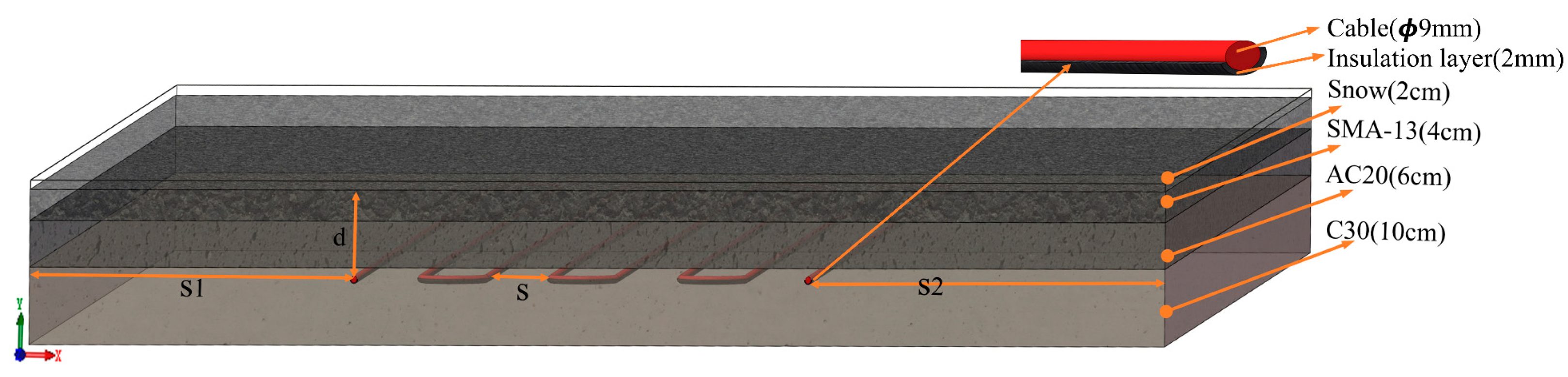
2.1. Heat Transfer Model

Numerical analysis methods have been extensively applied to assess the heat transfer performance of asphalt concrete [6,39,40,41]. Therefore, the heat transfer process during summer, winter, and cable system operation was simulated and analyzed using the finite element software ANSYS 2021R1.
In a heat transfer analysis, three types of mechanisms dominate heat transfer: conduction, convection, and radiation. In the heating process of the snow-melting system, heat is predominantly transferred via conduction between the cables and the pavement layers, while the influences of convection and radiation are relatively minor. Hence, it is hypothesized that the heat transfer within the pavement is by conduction. The pavement is in contact with the air, and heat is primarily transferred via convection. Thus, it is hypothesized that heat is transferred to the exterior of the pavement through convection. The boundaries on all four sides and the bottom are insulated, and a heat convection boundary condition is applied to the top, which satisfies the equation as Equation (1):
h ( T T e ) + λ T n = 0
Here, T e is the ambient temperature, λ is the thermal conductivity, and h is the convective heat transfer coefficient, which is determined by Equation (2):
h = 5.678 [ a + b ( v 0.304 ) n ]
v represents the wind speed in the environment (m/s), when 0 ≤ v ≤ 4.88, a = 1.09, b = 0.23, n = 1, and 4.88 ≤ v ≤ 30.48, a = 0, b = 0.53, n = 0.78.
The heat conduction of the road surface satisfies Fourier theorem, as in Equation (3):
ρ c v T t = x ( k T 1 x ) + y ( k T 1 y ) + z ( k T 1 z )
Here, ρ c v is the volumetric heat capacity (J/(m3·K)); T is the pavement temperature (k); and k is the pavement thermal conductivity (W/(m·K)).
The solar radiation is represented by Equation (4):
G a m b , i = F a m b , i e b ( T e ) F E P i ( T e )
Here, G a m b , i is the solar radiation intensity (W/m2); F a m b , i is the environmental angle coefficient; e b is the blackbody transmitting power (W/m2); F E P i is part of the radiated power (W/m2); and T e is the ambient temperature (K).
In particular, radiation boundary conditions need to be considered when solving the pavement heat balance equation, as shown in Equation (5):
q r = α E s
Here, q r is the radiation flux, W/m2; α is the absorption factor of solar radiation; and E s is the solar radiation intensity, W/m2.
The effective solar radiation is shown in Equation (6):
k T y = σ ε ( T 4 T e 4 )
Here, σ is 5.67 × 10⁻⁸ W·m−2·K−4; ε is the surface emissivity; T is the environment temperature, K; and T e is the surface temperature of the asphalt pavement, K.
The longitudinal and lateral dimensions of the heat transfer model were defined as 3.5 m and 1.75 m, respectively. Studies have shown that placing an insulation layer under the cable enhances snow-melting efficiency [25], and thus an insulation layer was installed beneath the cable. The model of the insulation layer is shown in Figure 1 (Scheme 2). From top to bottom, there is a 4 cm asphalt upper layer (SMA-13), a 6 cm asphalt lower layer (AC-20), and 10 cm C30 concrete, with heating cables and insulation layers embedded inside the concrete. S1 represents the distance of the heating cable from the left side (500 mm), S2 represents the distance of the heating cable from the right side (500 mm), d represents the distance of the cable from the road surface (115 mm), and S represents the cable spacing (100 mm). Meanwhile, the experimental model used a corrosion-resistant carbon fiber heating cable with a length of 28 m and an outer diameter of 9 mm. Table 1 provides the structural and thermal performance parameters for the two types of road surface models.
The model is meshed by adopting hexahedral elements. The pavement layer, carbon fiber heating cable, and insulation layer are meshed through hexahedral elements and the sweeping approach. Meanwhile, to calculate the temperature field of the winter system operation, in the finite element model, the cable model is set as a cylinder, and its heating effect is represented by the heating power density q c (W/m3), which is the power of the body heat source for 1 m3 of cable solids, which can be calculated by the following formula:
q c = 4 p π D 2
Here, D is the cable diameter (m) and p is the heating power of 1 m of cable (W/m). Applying the power density of heating to each cable can simulate the temperature field during system operation.
To compare the temperature field characteristics and snow-melting performance under different laying schemes, a thermal model with an insulation layer under the cable was set up, and the parameters of the designed thermal model are given in Table 2. To achieve a stable working state for the model or to effectively melt ice on the road surface, the operating time of the electric heating system is set at 18,000 s. The model design maintains three constant parameters: a distance of 500 mm from the left edge, a distance of 500 mm from the right edge of S2, and a cable spacing S of 10 cm.

2.2. Entransy Dissipation Analysis

Electric heating snow-melting pavement mainly involves heat transfer. According to the definition of entransy [34], the two sides of Equation (3) are multiplied by the temperature T to obtain the entransy balance equation during the heating process of asphalt snow-melting pavement:
ρ c v T T t = q ˙ T = q ˙ T + q ˙ T
Here, the left term of the equation is the growth rate of the entransy in the micro-element, the first term on the right of the equation is the input entransy, and the second term on the right is the entransy dissipation.
Further, through the integral equation, the energy balance equation under transient conditions can be established as Equation (9):
Ω ρ c v T T t d v = Σ q ˙ T e n d S + Ω q ˙ T d v
Here, v is the heat transfer area volume of the pavement (m3); S is the snowmelt pavement surface area (m2); n is the unit normal vector; T is the pavement temperature gradient, (K/m); q ˙ is the heat flux density vector; and T e is the ambient temperature (K).
The first term on the right side of Equation (9) is the entransy input from the cable, which is affected by the heat transfer and heat flow in different structural layers. The entransy dissipation caused by heat conduction within the asphalt pavement is the second term. The entransy growth rate within the asphalt pavement is the first item on the left. Equation (10) displays the total entransy dissipation E ω during heat transfer in asphalt pavement:
E ω = q ˙ T d v = k T T d V = k | T | 2 d V
Here, k is the thermal conductivity, W/(m·K), and ∇T is the temperature gradient, (K/m).
The entransy dissipation represents the loss of heat transfer capacity in the heat transfer process, indicating the irreversibility of the heat transfer process. A greater entransy dissipation signifies a higher level of irreversibility in heat transfer. When the heat flux density is constant, a smaller entransy dissipation corresponds to a smaller entransy transfer temperature difference. Conversely, when the temperature difference is given, a larger entransy dissipation results in greater heat transfer [32,34]. Therefore, the heat transfer capacity of the system can be intuitively measured by the magnitude of entransy dissipation.

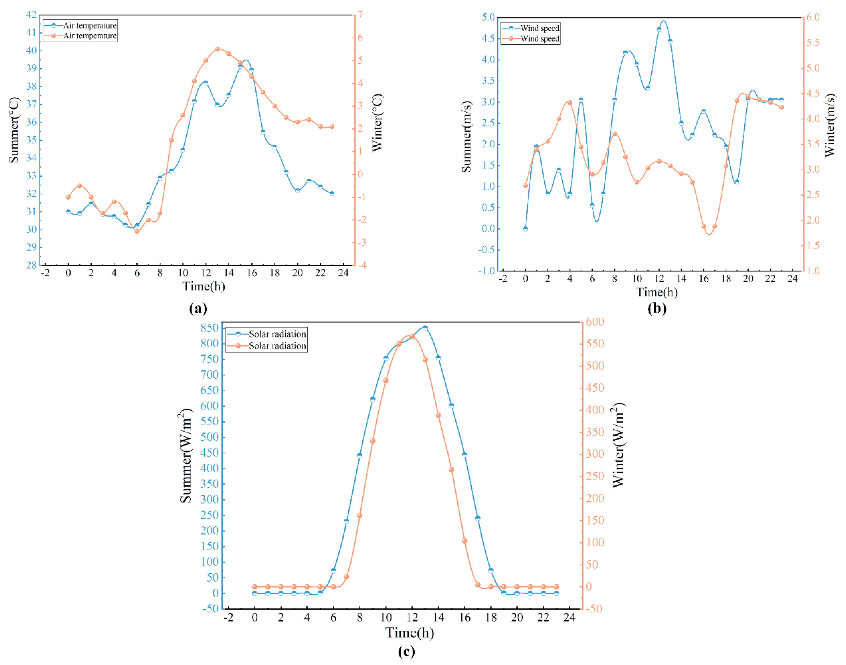
3. Field Experiment and Model Verification

To validate the feasibility of the 3D numerical simulation, verification tests were conducted. The construction of the outdoor model involved cement concrete pavement grooves, installing insulation layers, laying cable systems, and constructing asphalt pavements.

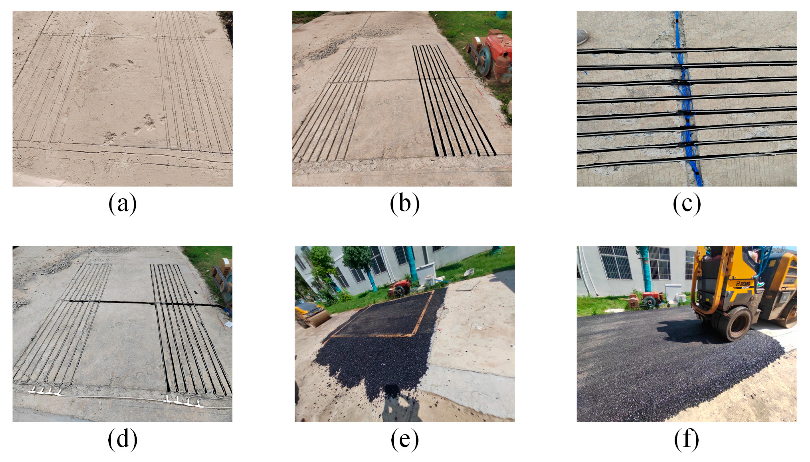
3.1. Outdoor Test Model Making

The carbon fiber cable snow-melting model is arranged on the concrete pavement in this paper. The model size is 350 cm in the longitudinal (Y direction) and 350 cm in the transverse (X direction). From top to bottom, the structure consists of a 4 cm asphalt upper layer (SMA-13), a 6 cm asphalt lower layer (AC-20), and a 10 cm C30 layer. Figure 2 presents the process of making an outdoor model. The groove depth of the concrete pavement is 1.5 cm to place the heating cable, shown in Figure 2a, and then the insulation layer in Figure 2b, the internal temperature sensor in Figure 2c, and the installation cable in Figure 2d are arranged. Finally, two layers of asphalt are placed on top, shown in Figure 2e, for compaction, shown in Figure 2f.
The thermocouple arrangement point is shown in Figure 3. The first layer of the surface’s serial number is #14, #15, #16, #17, #18, #19; the second layer’s, 11.5 cm from the surface, serial number is #1~#5, #6, #8, #9, #12; and the third layer’s, 11.7 cm from the surface, serial number is #7, #11, #13.

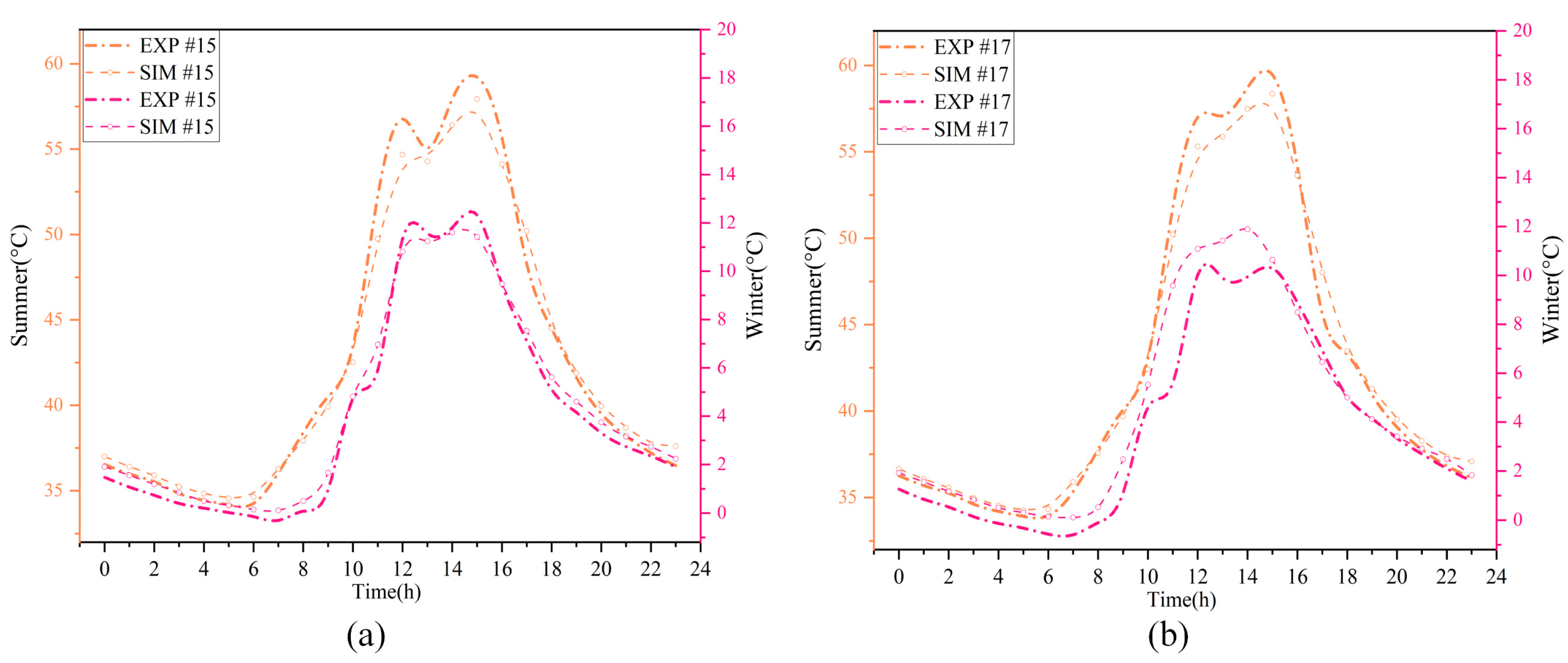
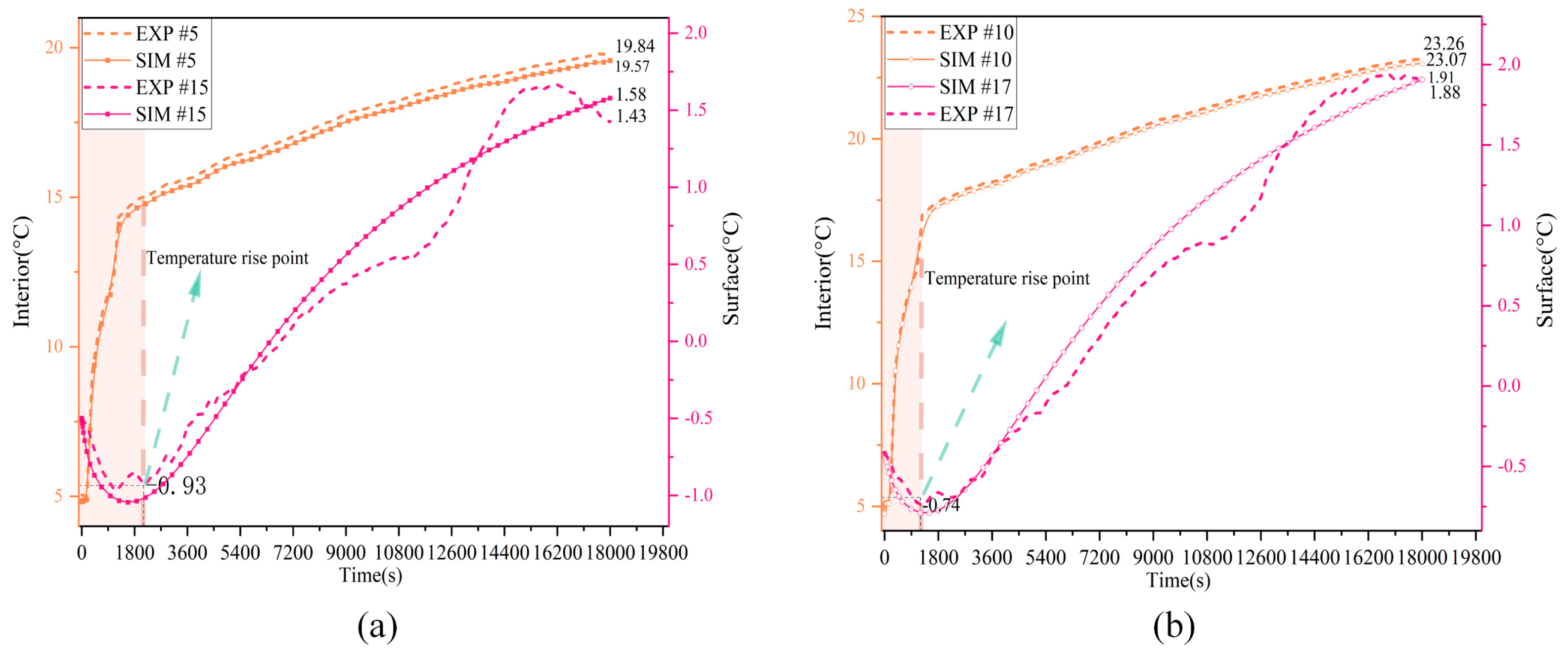
3.2. Experimental Results and Verification

The pavement temperatures were measured in early August and late December 2023, and the average temperature for one day of each week was given (the heat transfer behavior at the average temperature is more representative and better describes the heat transfer behavior and characteristics in most cases); the wind speed and solar radiation intensity for those days are shown in Figure 4. The meteorological parameters used in the heat transfer model were obtained from the European Centre for Medium-Range Weather Forecasts and the China Meteorological Administration (Hongshan District, Wuhan, China). Once the corresponding parameters are determined, the heat transfer simulation can be conducted accordingly. Figure 5 illustrates the temperature cloud diagram of Scheme 2 during summer nights and the temperature cloud diagram of cable during winter.
Figure 6 shows the thermal imaging picture of the surface during heating, demonstrating that the surface temperature of the road is significantly higher above the cable compared to other areas. Figure 7 illustrates the melting process, where surface snow begins to melt after one hour of heating and completely disappears after five hours. These results confirm that the designed model effectively melts snow on the road surface.
Figure 8 and Figure 9 compare the measured surface temperature values (the average temperature) and the simulated data. The simulation results show some differences compared to the measured temperature data. This is because the actual road heat transfer process is more complex than the simulation model, as it involves factors such as the influence of the surrounding environment and internal heat transfer within the road structure. These additional variables therefore lead to slight discrepancies between the simulated and measured values. However, the simulated temperature distribution of the asphalt road surface demonstrates strong consistency with the measured temperature data.
Meanwhile, as shown in Figure 9, the temperature around the underground cable in the road surface rapidly rises at the beginning of heating, while the surface temperature shows a decrease to varying degrees, which is different from the findings of some researchers [6,25,26]. This may be because their studies were mostly conducted indoors or through finite element analysis, or it may be related to the heating time chosen in this study.

4. Results and Discussion

To determine the temperature field characteristics and heat transfer properties between these layers, an analysis was conducted on the temperature, temperature change rate, temperature gradient change characteristics, and entransy dissipation of each structural layer.

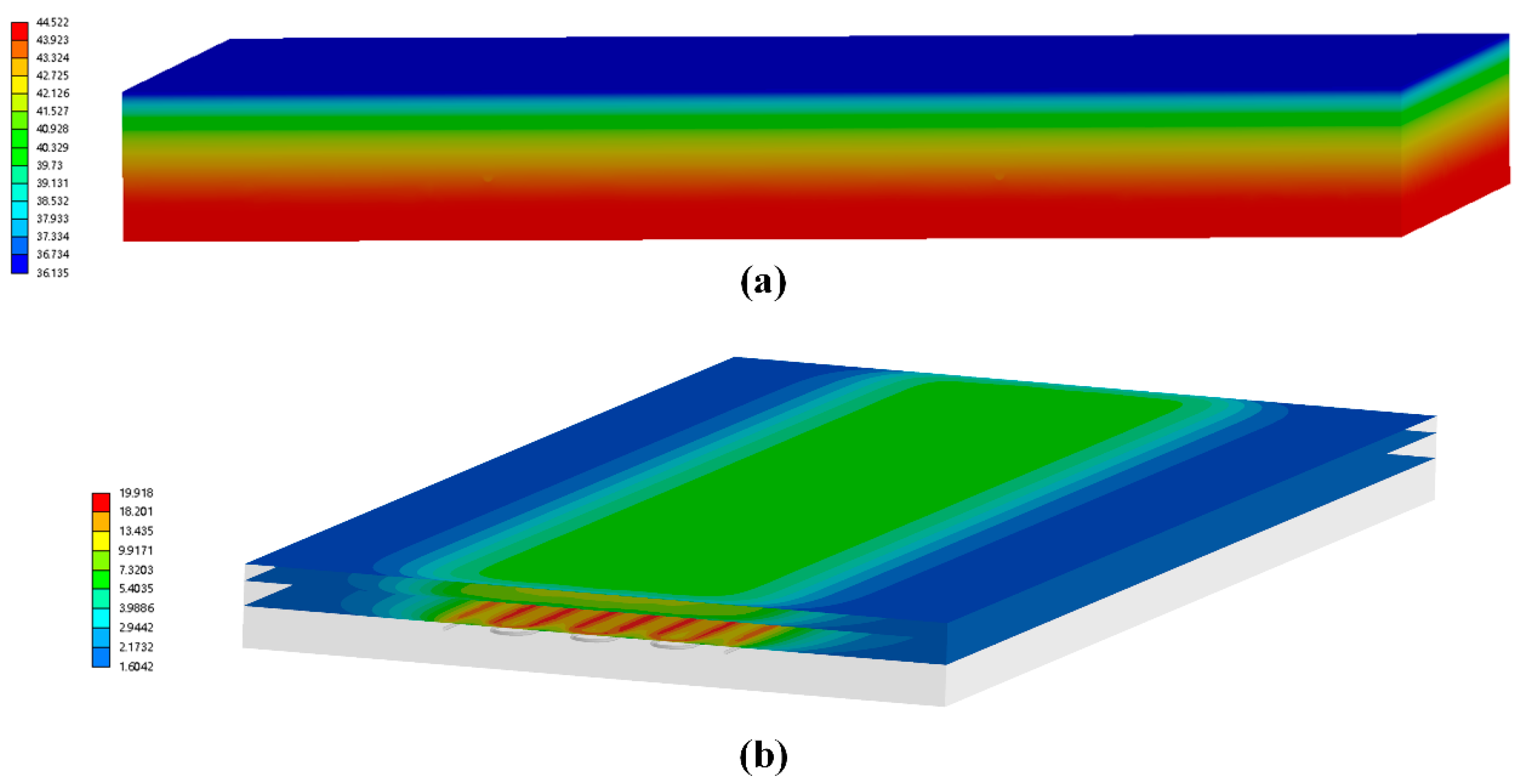
4.1. Temperature Field Distribution Characteristics

The electric heating system is turned on during the winter when there is snow and ice, and it is turned off during the summer and winter without snow. In this paper, the temperature field characteristics of the system during the summer and winter when it is turned off, as well as during the winter when it is running, are analyzed.

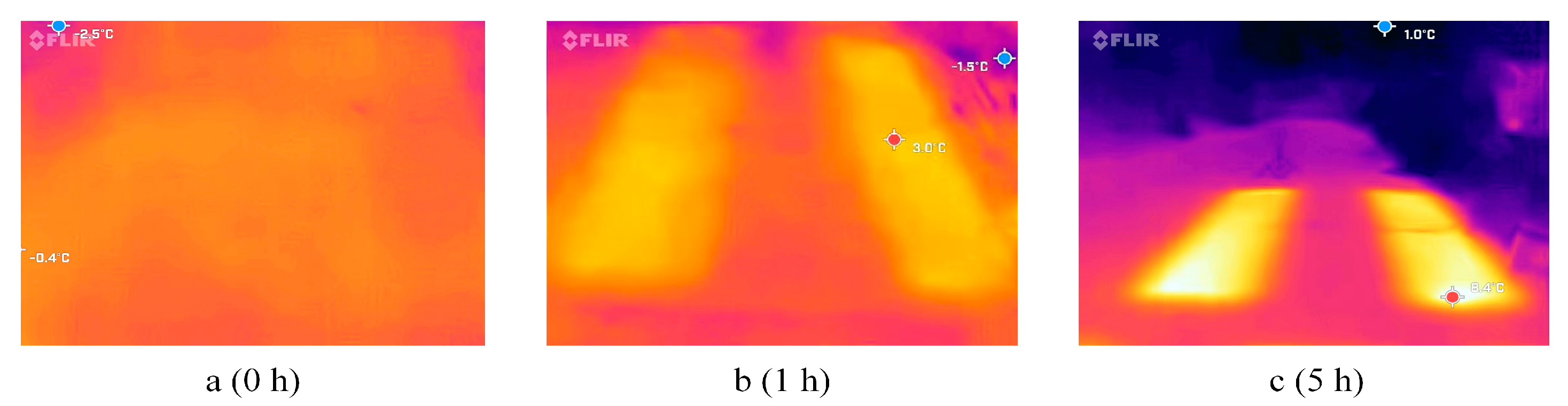
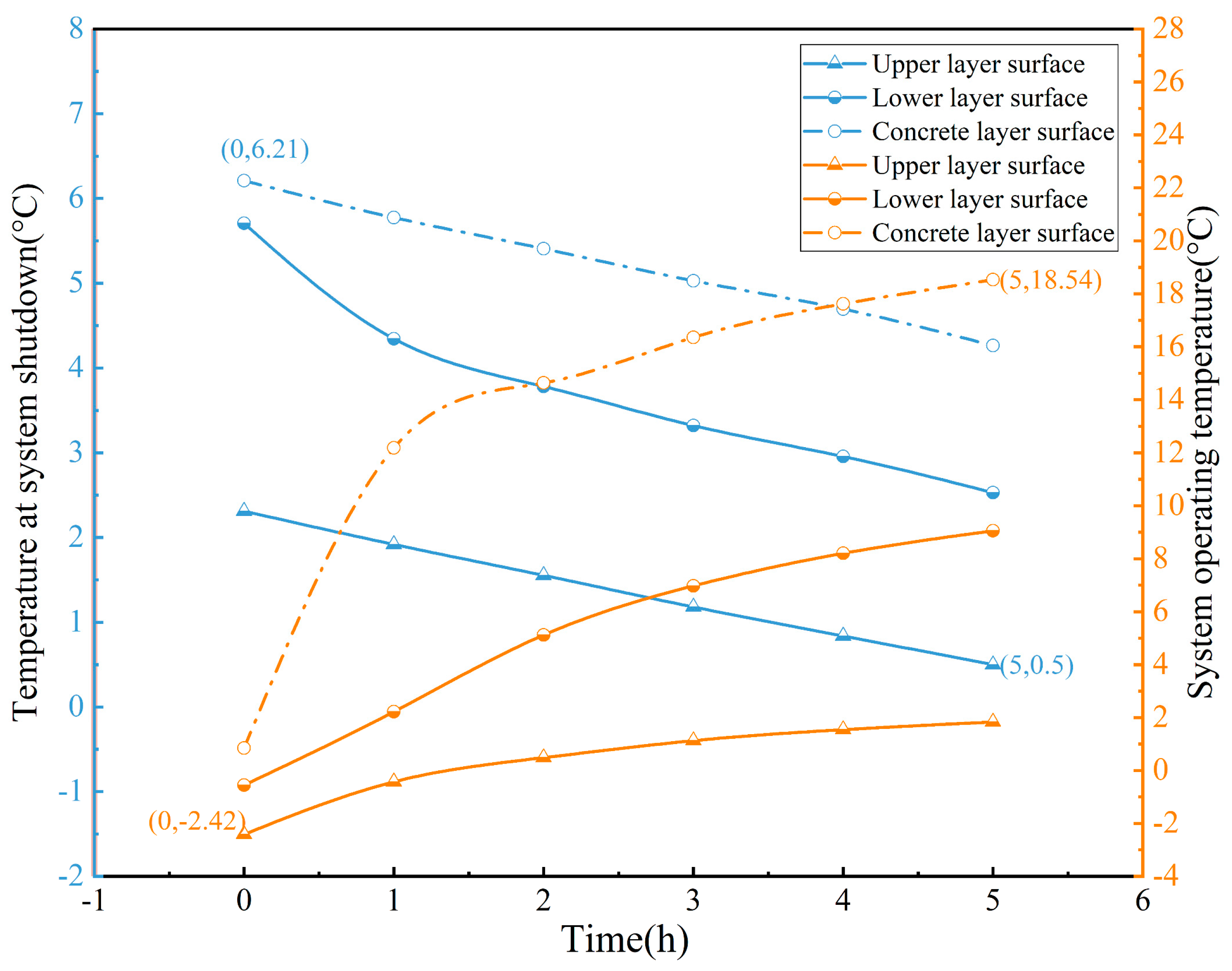
4.1.1. Analysis of Temperature Distribution Characteristics

Figure 10 shows that the temperature changes in Scheme 1 and Scheme 2 are consistent in summer and winter. During the night in summer and winter, the ambient temperature affects the road surface model, and the overall temperature is in a downward trend. During the day, the road surface is affected by solar radiation, the surface temperature begins to rise, and then the heat gradually transfers to the road surface. Due to the resistance in the heat transfer process, it can be seen that the temperature change in the inner part of the road surface is slower than that of the surface.
It is necessary to select an appropriate heating strategy to reduce energy consumption based on the distribution of road surface temperature. Figure 10 shows that the temperature changes of Scheme 1 and Scheme 2 are consistent in summer and winter. During the night in summer and winter, the ambient temperature affects the road surface model, and the overall temperature is in a downward trend. During the day, the road surface is affected by solar radiation, and the surface temperature begins to rise, and then the heat gradually transfers of heat the road surface. Due to the resistance in the heat transfer process, it can be seen that the temperature change in the inner part of the road surface is slower than that of the surface.
In the summer, due to solar radiation and the properties of asphalt materials, the ambient temperature remains below 40 °C while the road surface reaches nearly 60 °C, with the largest temperature fluctuations occurring on the surface. In the first scheme, the maximum temperature difference on the road surface during summer is 23.29 °C, while in winter it is 11.5 °C. In the second scheme, the maximum temperature difference on the road surface during summer is 24.03 °C, and in winter, it is 11.78 °C.
During winter conditions, pavement temperature governs the likelihood of freezing. From midnight to 7 a.m., when the pavement temperature exhibits a gradual decline, this period is associated with the highest freezing risk. To avoid the influence of the load from vehicles above the cable during operation and the internal high temperature of the cable on the road surface (as there are fewer vehicles at night), based on the temperature distribution of the road surface in Scheme 1 and Scheme 2, this paper chooses to set the working hours of the cable to 0 a.m. to 5 a.m. Figure 11 and Figure 12 show the temperature comparison between the system in operation during winter and when it is turned off.
Between midnight and 5:00 a.m., the surface temperatures of the upper asphalt, lower asphalt, and concrete layers gradually decreased when the system was shut down during winter. Additionally, the pavement temperatures exhibited an increasing trend with depth. When the system began operation, the pavement temperature gradually increased. The surface temperature of the concrete layer rose most noticeably, while the temperature of the upper layer of asphalt was lower than that of the lower layer. The operation of the system altered the temperature distribution within the pavement.
When the electric heating system is turned off, the surface temperature of the road is primarily influenced by external environmental factors, showing a clear temperature decrease at midnight and starting to rise after 8 a.m. due to ambient temperature and solar radiation. It reaches its peak around 3 P.M. before gradually decreasing as ambient temperature and solar radiation diminish. When the system is operational, the surface temperature is notably higher due to internal heat flow intervention. Overall, the temperature of the snow-melting road surface exhibits an upward trend, reaching the critical temperature of 0 °C within two hours.

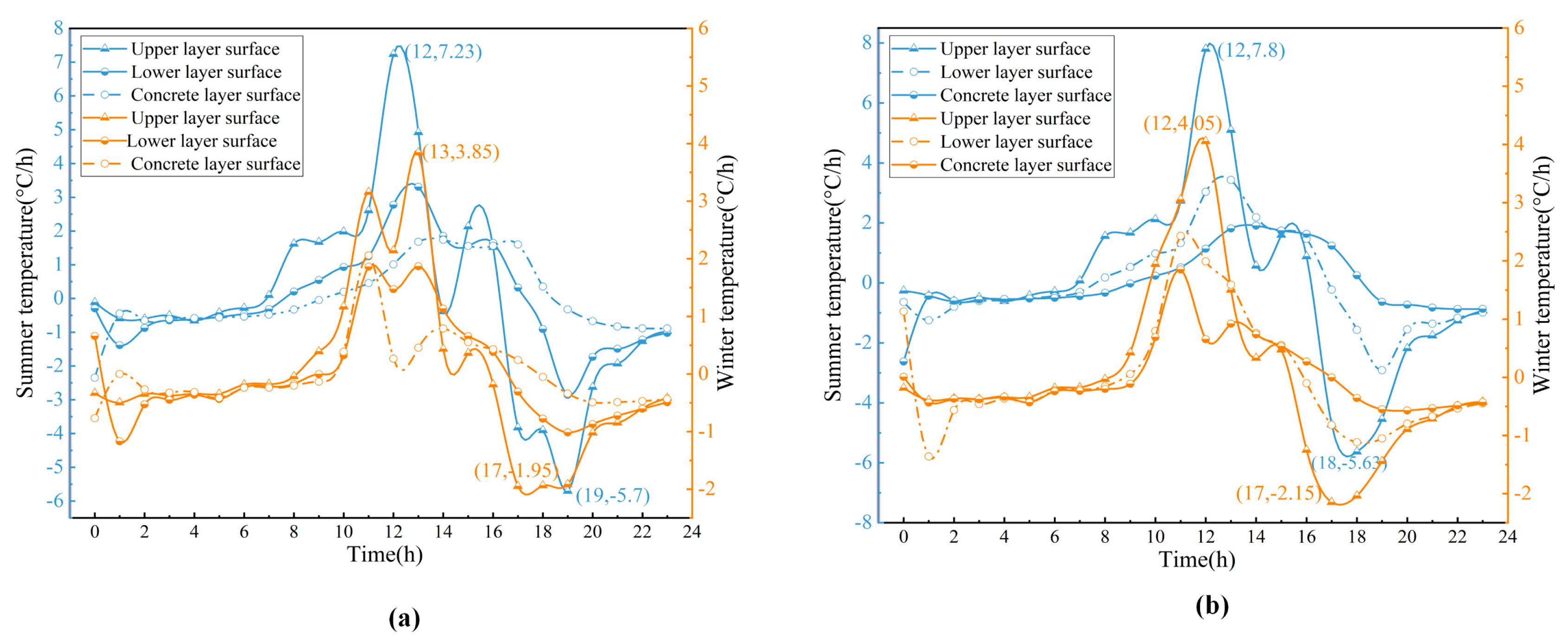
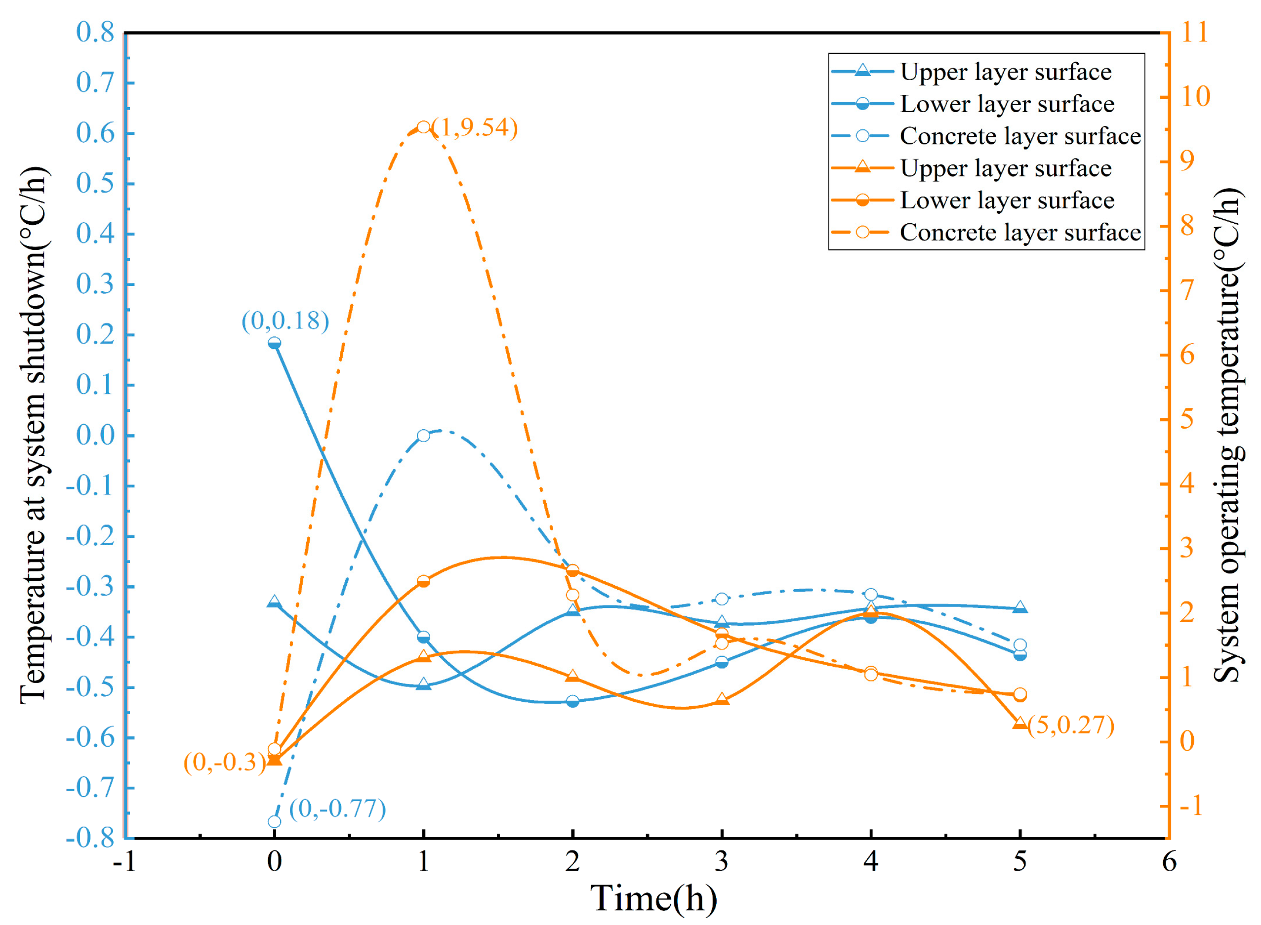
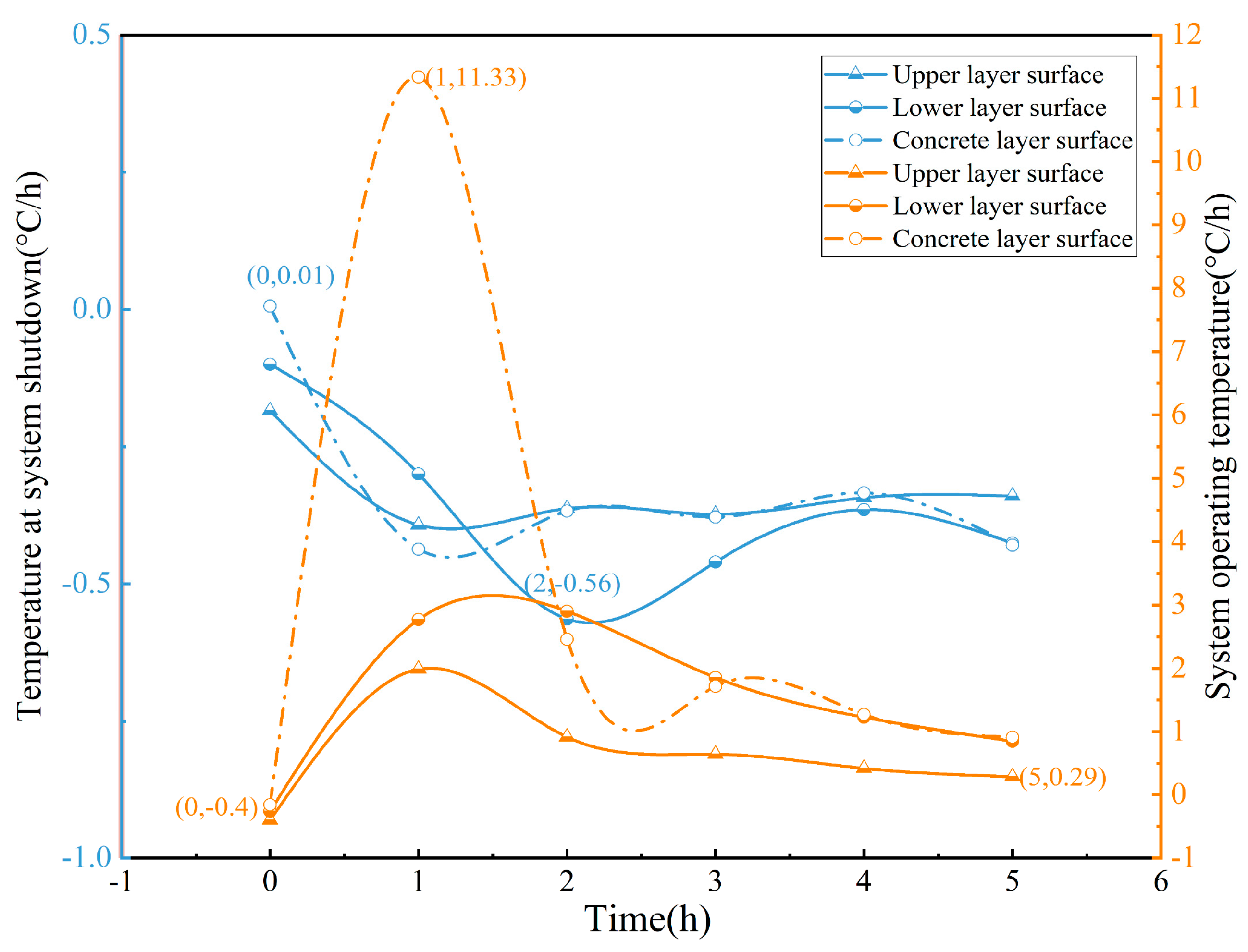
4.1.2. Temperature Change Rate Analysis

Based on the closed-system and operational data, this study analyzes the daily temperature change rate at different depths of the road structure. Figure 13 shows the temperature change rate patterns at different layers of the road structure under the two schemes. Figure 14 and Figure 15 show the temperature change rate comparison of different structural layers during operation and shutdown under the two schemes.
As shown in Figure 13, the daily temperature change rate of the pavement exhibits approximately sinusoidal behavior. Taking the temperature change rate of the upper layer of the asphalt surface as an example (Scheme 1, summer), the rate is minimal between 0:00 and 6:00 in the morning, varying between −1 °C/h and 1 °C/h. As solar radiation increases, the temperature change rate of the upper layer of the asphalt surface rises rapidly, reaching its peak of 7.23 °C/h at noon. Thereafter, it decreases steadily, reaching 0 °C/h by 16:00, indicating that the pavement surface warming process is complete. As solar radiation declines, the road transitions from heat absorption to cooling, with the temperature change rate on the road gradually increasing. This cooling rate reaches its maximum of −5.7 °C/h at 19:00 (Scheme 1).
Figure 13 also demonstrates that as depth increases, the rate of temperature change slows. The maximum temperature change rate at the surface of the asphalt upper layer is 7.8 °C/h, whereas the highest temperature change rate at the surface of the asphalt lower layer is 3.43 °C/h (Scheme 2). This phenomenon suggests that environmental elements, particularly sun radiation, affect temperature changes on the road surface. On the other hand, it demonstrates that heat transfer on the road surface is accompanied by energy loss.
When the system is in operation, the cables embedded within the road will transfer heat to the road surface to achieve snow melting or ice removal. However, during the winter, the surface temperature of the road is low, and the high temperature inside the road and the low temperature of the road surface are some of the important problems that the snow-melting system needs to face in application. Therefore, the temperature change rates of different structural layers during system shutdown and operation were also compared and analyzed, as shown in Figure 14 and Figure 15.
During the initial operation of the system (0–60 min), the temperature change rate on the concrete surface and the asphalt sublayer surface increased sharply, with the concrete surface reaching a maximum of 9.54 °C/h. This indicates that the cable system has a significant temperature impact on the concrete layer during the initial operation period. After that, the temperature change rate gradually decreased. After two hours, the temperature change rate stabilized at less than 2 °C/h, and the temperature change rate at this time was less than that when the system was shut down. This demonstrates that the embedding of the cable heat source contributes to a more stable temperature change in the road structure in the later operation period (Scheme 1).
Meanwhile, Figure 15 shows the influence of the insulation layer under the cable on the rate of temperature change, with the maximum rate of surface temperature change on the concrete layer being 11.33 °C/h, which is 18.76% higher than the model without insulation. After 5 h, the rate of surface temperature change on the asphalt upper layer is 0.29 °C/h, which is higher than the rate of 0.27 °C/h in Scheme 1. Therefore, the arrangement of an insulation layer under the cable is beneficial to the rise in the surface temperature of the road, thereby improving the efficiency of snow melting.

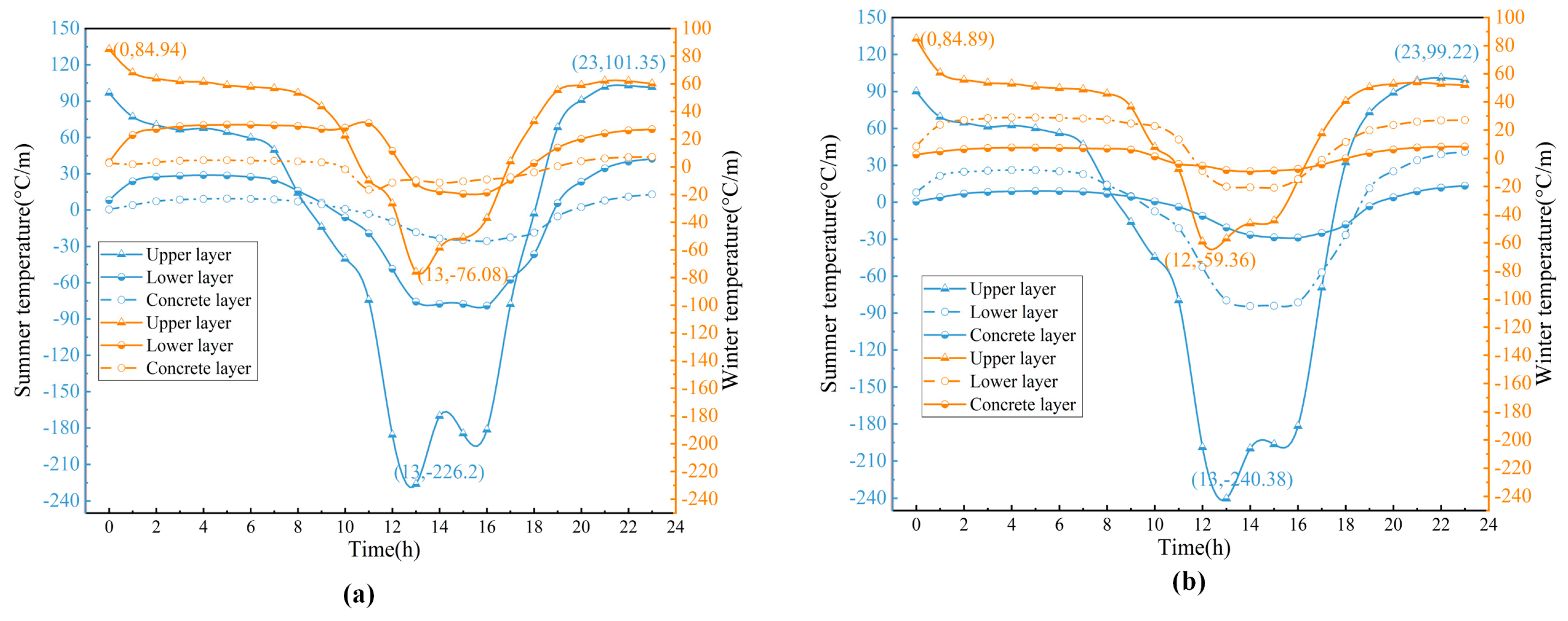
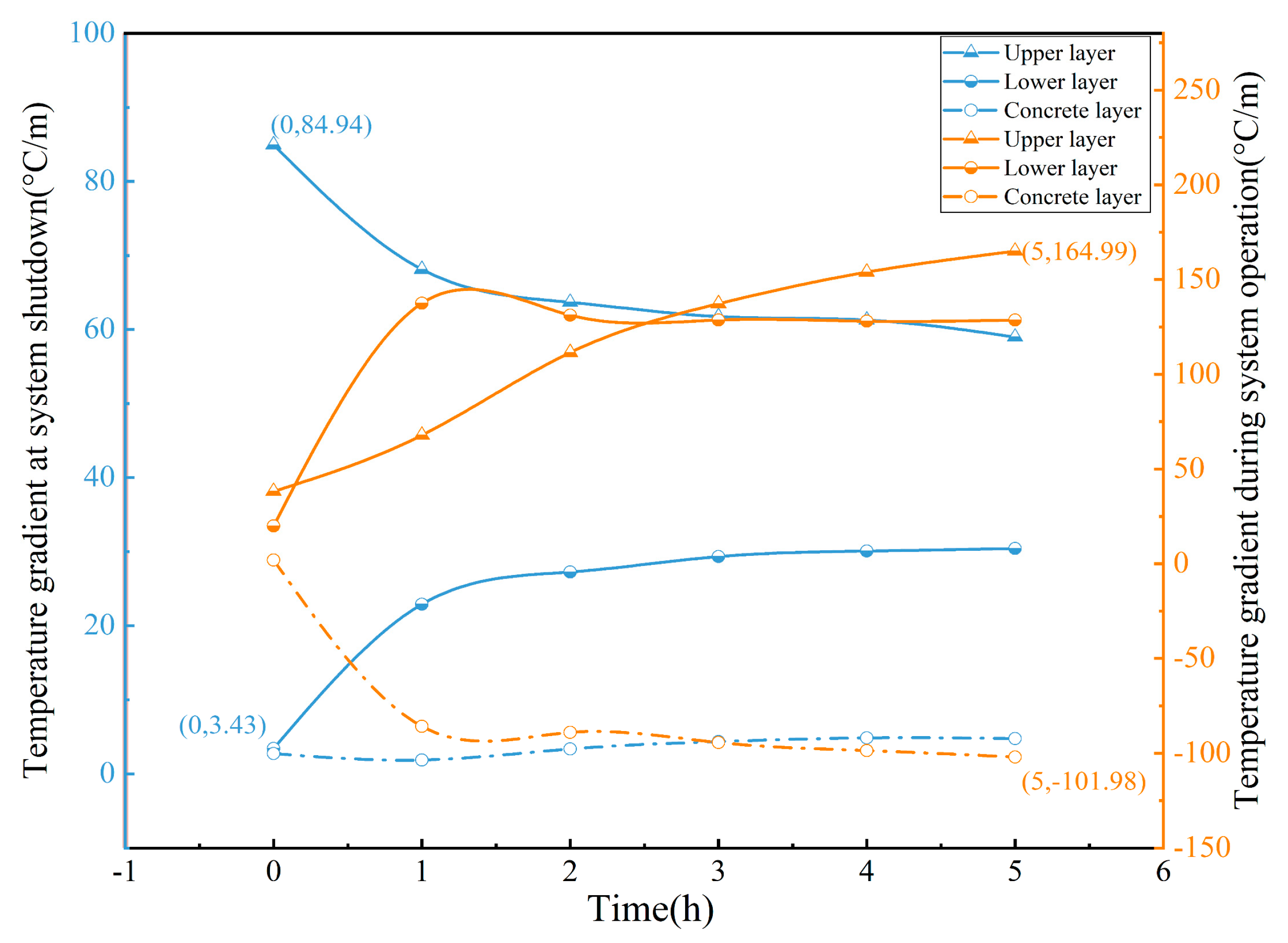
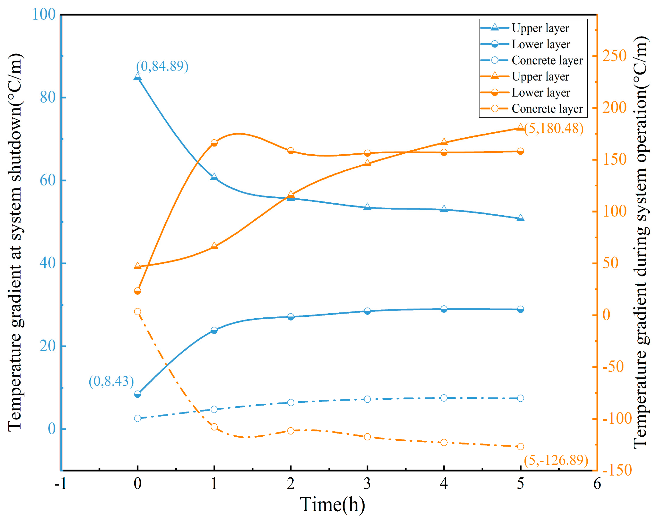
4.1.3. Analysis of Temperature Gradient Variation

The temperature gradient is the most fundamental reason for the road structure to produce temperature stresses, which directly relates to the structural safety of snow-melting roads [42]. This paper calculates the temperature gradient along the depth direction of different pavement layers, as shown in Figure 16, which gives the hourly temperature gradient of various layers in different seasons for two schemes.
The variation in the temperature gradient in summer and winter is shown in Figure 16, and the temperature gradient shows a single peak variation. For example, the temperature gradient at the upper surface of the asphalt layer at night due to the lack of solar radiation; at this time, the internal structure of the road surface presents a positive temperature gradient, and the maximum positive temperature gradient reaches 101.35 °C/m (Scheme 1). During the day, as solar radiation increases, the road surface temperature gradually rises. Consequently, the temperature gradient within the pavement structure shifts from positive to negative, reaching a peak of −226.2 °C/m at 13:00. Additionally, with increasing depth, the gradient amplitude gradually decreases, and its peak occurs later.
Figure 17 and Figure 18 show that the temperature gradient of the pavement follows a consistent pattern under both schemes. Initially, the structural temperature near the embedded cable gradually increases as the system operates. Due to the energy loss during heat transfer, the temperature difference between the embedded cable and the pavement surface gradually increases, rapidly increasing the temperature gradient. By 5 a.m. (after 300 min of operation), the concrete layer temperature gradient reaches −101.98 °C/m, which is 21.42 times the temperature gradient of the concrete layer at system shutdown (Scheme 1). As the operating time of the system increases, the temperature around the cable gradually stabilizes. It is evident that the temperature gradient of the lower asphalt layer initially increases and then slowly stabilizes, while the temperature near the pavement surface continues to rise, leading to an increasing temperature gradient. Specifically, the temperature gradient of the upper asphalt layer reaches 164.99 °C/m, which is 2.8 times higher than that of the upper asphalt layer when the system is closed. Furthermore, in the insulation model, the temperature gradient generated by the upper asphalt layer is 9.39% larger than that of the without-insulation model.
The heat source from the cable alters the heat transfer process within the pavement structure, disrupting the distribution of temperature fields and changing the temperature gradient. The temperature gradient is closely linked to the structural safety of snow-melting pavements. Therefore, it is essential to implement an appropriate operational strategy for the cable system to minimize damage to the pavement structure during operation.

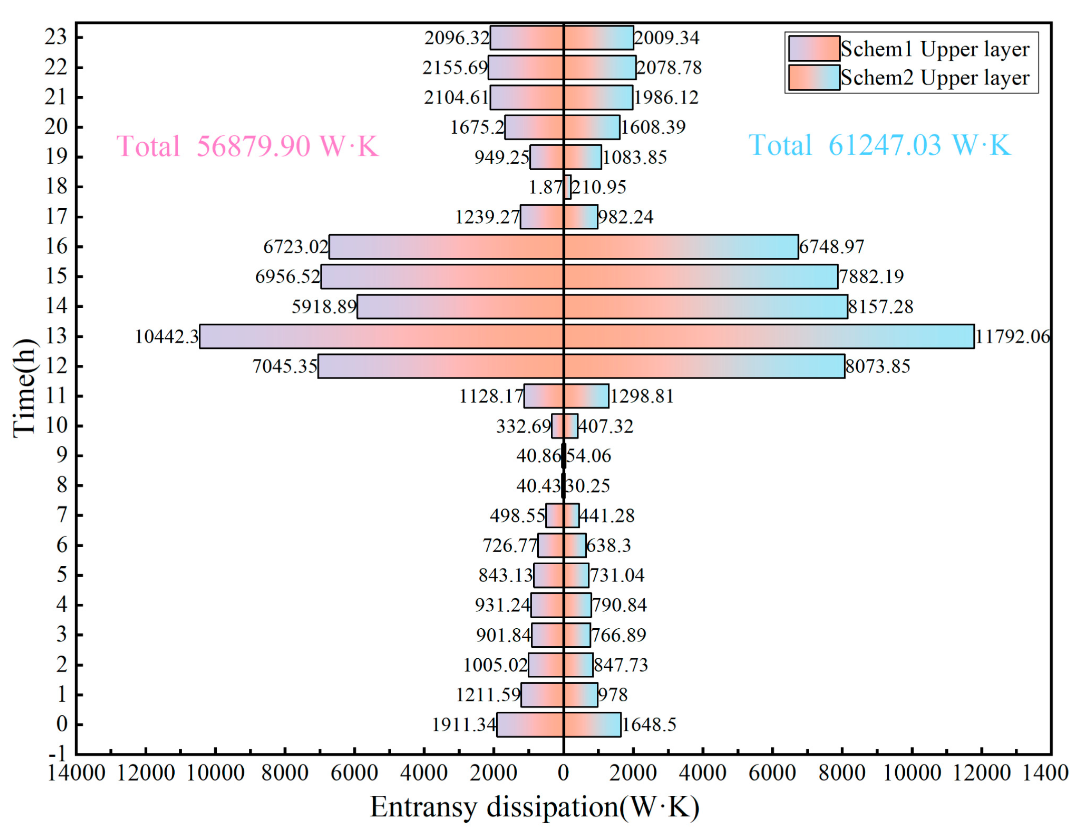
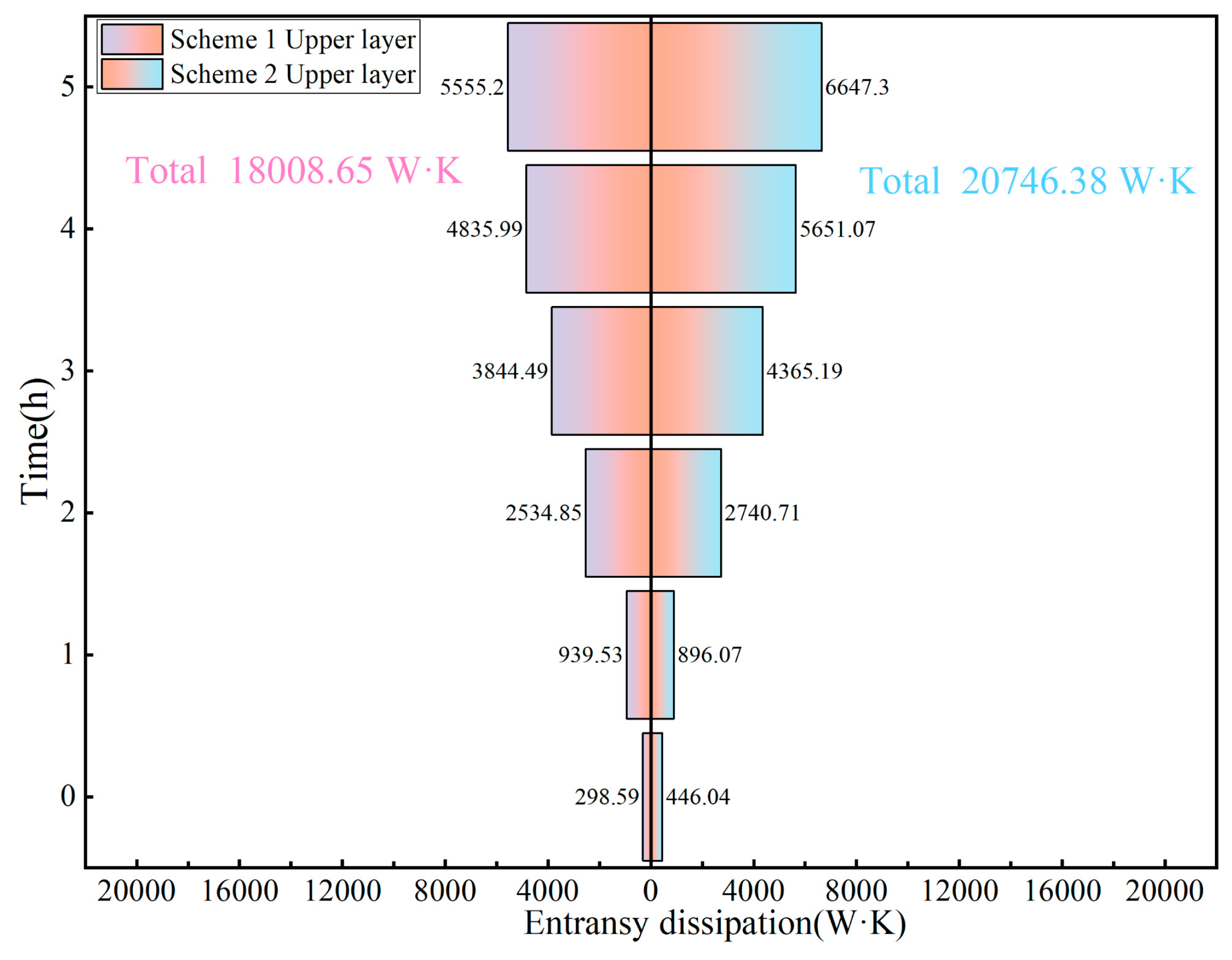
4.2. Analysis of Heat Transfer Entransy Dissipation

This section is the same as Section 4.1: it analyzes the distribution of entransy dissipation when the system is closed in summer and winter and when the system is operating in winter.

4.2.1. Heat Transfer Entransy Dissipation in Summer

In engineering practice, the design of heat transfer structures serves two purposes: to maximize heat flux under constant temperature difference and to minimize temperature difference under constant heat flux. In other words, for constant heat flux, the minimum temperature difference corresponds to the minimum entransy dissipation. Therefore, for constant heat flux, smaller entransy dissipation leads to higher heat transfer efficiency.
Figure 19, Figure 20 and Figure 21 present the average hourly entransy dissipation of the upper asphalt layer, lower asphalt layer, and concrete layer on a summer day. It is evident from the perspective of overall entransy dissipation that the upper asphalt layer demonstrates the highest dissipation while the concrete layer exhibits the lowest. The one-day entransy dissipation of the upper asphalt layer is 56,879.90 W·K (Scheme 1). This value is 13.14 times higher than that of the concrete layer and 2.32 times higher than that of the lower asphalt layer. The entransy dissipation of the upper and lower layers of asphalt in Scheme 1 accounts for 94.95% of the total entransy dissipation (Scheme 2 is 94.43%). Therefore, in snowmelt pavement, most entransy dissipation occurs in the asphalt layer during heat transfer, resulting in significant heat absorption by this layer and limited transfer to the lower layer. Thus, the asphalt layer’s entransy dissipation diminishes the pavement’s overall heat transfer capacity.
From the perspective of entransy dissipation generated during each period, it is observed that the upper layer of asphalt mainly generates entransy dissipation from noon to 4 pm, while the lower layer of asphalt exhibits concentrated entransy dissipation from 1 pm to 5 pm. Additionally, the concrete layer shows a concentration of entransy dissipation from 2 pm to 6 pm. This indicates the presence of resistance in the heat transfer process, and the dissipation of entransy decreases as the depth increases. As heat is transferred, there is a decrease in the heat flux through both the asphalt layer and the concrete layer. This reduction in heat flux density and temperature gradient ultimately leads to a corresponding decrease in the entransy dissipation of both layers.
Compared with Scheme 1, it can be seen that the entransy dissipation generated in each structural layer of Scheme 2 is greater than that of Scheme 1, which indicates that the arrangement of the insulation layer increases the thermal resistance of the pavement model and heat accumulates above the insulation layer, thus unable to be conducted in time. The arrangement of the insulation layer reduces the pavement’s heat transfer capability in summer.
In conclusion, the decrease in the heat transfer capacity of the asphalt layer results in the accumulation of heat in both the upper and lower layers of asphalt. This leads to a decrease in heat flux and the temperature gradient within the structural layer, ultimately resulting in the reduced entransy dissipation of the concrete layer. The arrangement of the thermal insulation layer reduces the heat transfer capacity of the pavement in summer and increases the entransy dissipation.

4.2.2. Heat Transfer Entransy Dissipation in Winter

Figure 22, Figure 23 and Figure 24 illustrate the distribution of entransy dissipation in different structural layers during each hour when the system is closed in winter. Specifically, the entransy dissipation of the upper asphalt layer is greater than that of the lower asphalt layer, which in turn is greater than that of the concrete layer. Furthermore, it is worth noting that the combined entransy dissipation of the upper and lower asphalt layers accounts for 62.27% and 32.69%, respectively.
From the period of entransy dissipation distribution, the entransy dissipation of the asphalt upper layer is primarily observed from 1:00 a.m. to 8:00 a.m., while the asphalt lower layer experiences dissipation mainly from 2:00 a.m. to 10:00 a.m. This is different from the distribution in summer. In winter, the internal temperature of the pavement remains relatively stable. The asphalt upper layer is most affected by external factors, with the greatest temperature fluctuations occurring at night. As a result, entransy dissipation caused by both the upper and lower asphalt layers occurs largely at night. The concrete layer is different from the asphalt layer. During winter, the stability of the temperature increases with the depth of the pavement, and the heat flux through it is significantly lower compared to both the upper and lower layers of asphalt. The temperature variation in the concrete layer is primarily influenced by internal heat conduction. As a result, the entransy dissipation generated by the concrete layer is minimal, with concentration occurring at noon. This can be attributed to solar radiation during this time, which plays a predominant role (Scheme 1).
Differing from the summer season, Scheme 2 exhibits a smaller entransy dissipation in winter compared to Scheme 1. The total entransy dissipation of the asphalt upper layer and asphalt lower layer is also 15.41% lower than that of Scheme 1. This observation indicates that the arrangement of insulation layers effectively reduces heat loss from the model during winter, thereby enhancing the heat transfer efficiency of the pavement
The total entransy dissipation generated by the pavement in each structural layer in winter is consistent with the distribution law in summer. However, the entransy dissipation of the asphalt layer in winter is mainly distributed at night rather than at noon. Scheme 2 reduces the entransy dissipation in winter, which is beneficial to the heat transfer of the pavement. According to the distribution of entransy dissipation in winter, the heat transfer capacity of the road surface decreases at night, which makes the road surface more likely to freeze, and the temperature below cannot be transmitted to the road surface. Therefore, based on the distribution of entransy dissipation in winter, the time selection for the deicing scheme in this paper is reasonable.
Figure 25, Figure 26 and Figure 27 show the hourly entransy dissipation of the asphalt upper layer, asphalt lower layer, and concrete layer of the winter system during operation. It is evident that as the system operates, there is an increase in entransy dissipation in both the concrete layer and the asphalt upper layer over time, while the entransy dissipation in the asphalt lower layer tends to stabilize. Within one to five hours of operation, the entransy dissipation of the asphalt upper layer increased by 4.92 times, while the asphalt lower layer decreased by 12.48% and the upper asphalt layer increased by 41.5%. This indicates that the temperature uniformity of the lower asphalt layer is getting better with time, while the concrete layer and the upper asphalt layer have not yet reached a stable state, so the entransy dissipation is constantly increasing. At the same time, there is a difference in the distribution of entransy dissipation between when the system is closed in summer and winter. The maximum entransy dissipation occurs in the asphalt lower layer, while the minimum occurs in the asphalt upper layer. In Scheme 2, the entransy dissipation of the asphalt upper layer is 15.2% greater than that of Scheme 1, and the total entransy dissipation of the asphalt lower layer is 48.15% greater than that of Scheme 1. Additionally, the entransy dissipation of the concrete layer is 55.96% greater than that of Scheme 1. This indicates that arranging a heat insulation layer increases pavement entransy dissipation, primarily affecting both the asphalt lower layer and concrete layers.
During system operation, the lower layer of asphalt and the concrete layer absorbs a significant amount of heat, resulting in reduced heat transfer to the upper layer of asphalt. The heat for snow melting on the road surface is generated by the cable, but the dissipation of entransy from the lower asphalt and concrete layers hinders effective upward heat transfer, thereby impacting winter snow-melting efficiency. The arrangement of the insulation layer can improve the efficiency of snow melting.
The thermal properties of the pavement surface affect the distribution of internal and surface temperatures. During system shutdown, the surface temperature of the roadway in both summer and winter tends to decrease at midnight, with the asphalt layer being the main reason for the reduction in the pavement’s heat transfer. During system operation, a significant temperature shock occurs during the initial stage. The heat generated by the cable affects the heat transfer process in the pavement structure. This disruption affects the distribution of temperature throughout the pavement structure and modifies both the temperature gradient and entransy dissipation within the pavement. The arrangement of the insulation layer is not conducive to heat transfer from the road surface in summer; however, it is conducive to melting snow and ice on the road surface in winter.

5. Conclusions

In this study, the distribution characteristics of the temperature, temperature change rate, and temperature gradient of the asphalt snowmelt pavement structure are investigated during the closed state of the system in summer and winter, as well as during the system’s operation in winter. Furthermore, the heat transfer characteristics of the asphalt snowmelt pavement are explored using the entransy theory, and the finite element results were verified through field experiments. The results indicate the following:
When the system is closed during summer and winter, the following occurs:
The temperature change in the road surface is influenced by environmental factors such as solar radiation, and the heat transfer process in asphalt snow-melting pavement structures involves energy loss, resulting in a gradual decrease in the rate of temperature change and temperature gradient with depth.
The heat transfer characteristics of the pavement affect the internal and surface temperature distribution of the pavement, the surface temperature tends to decrease at midnight in both summer and winter, and the entransy dissipation generated within the asphalt layer reduces the heat transfer capacity of the pavement.
The total entransy dissipation of different structural layers in winter is consistent with that in summer. However, the main reduction in the heat transfer capacity of the asphalt layer in winter occurs at night, not during the day.
During winter operation of the system, the following occurs:
The cable heat source has a significant impact on the heat transfer process of the pavement structure, changing the temperature field distribution and temperature gradient, which in turn affects the entransy dissipation.
During snow melting, entransy dissipation primarily occurs in the lower asphalt layer and concrete layer. A reduced heat transfer capacity impedes effective upward heat transfer, resulting in decreased winter snowmelt efficiency. The insulation layer model improves snow-melting efficiency.
The main loss of heat transfer capacity of the pavement layer in winter occurs at night. Therefore, setting the system to operate from 0:00 to 5:00 is effective at preventing pavement icing.
The findings of this study contribute to a better understanding of heat transfer characteristics in snow-melting pavements, providing a theoretical and practical foundation for electrically heated asphalt pavement snow-melting systems. Future research should focus on (1) optimizing the design of the insulation layer; (2) multi-factor coupling analysis incorporating parameters such as wind speed, humidity, thermally conductive materials, and thermal conductivity coefficients; and (3) a comprehensive long-term performance evaluation of pavement systems.

Author Contributions

Conceptualization, K.X. and Z.C.; methodology, K.X.; software, K.X.; validation, Z.C., H.X. and M.Z.; formal analysis, M.Z.; investigation, H.X.; resources, Z.C. and M.Z.; data curation, Z.W.; writing—original draft preparation, K.X.; writing—review and editing, Z.C.; visualization, M.Z. and Z.W.; supervision, Z.W.; project administration, H.X.; funding acquisition, Z.C. All authors have read and agreed to the published version of the manuscript.

Funding

This work was supported by the Key Research and Development Program of Hubei Province (No. 2023BAB024) and the Technology Innovation Project of Hubei Province (No. 2023BEB010).

Institutional Review Board Statement

Not applicable.

Informed Consent Statement

Not applicable.

Data Availability Statement

The data showcased in this investigation are accessible upon inquiry directed to the corresponding author. However, it should be noted that the data cannot be made publicly accessible due to copyright constraints associated with collaborative developers.

Conflicts of Interest

Authors Mengjun Zhu and Zhiyong Wang were employed by China Railway Siyuan Survey and Design Group Co., Ltd. The remaining authors declare that the research was conducted in the absence of any commercial or financial relationships that could be construed as a potential conflict of interest.

References

  1. Zhao, Y.; Liu, X.; Wei, D. Asphalt Mixture with Nucleus-Shell Structural Microwave Enhanced Aggregate: Structure Design, Preparation and Performance. Case Stud. Constr. Mater. 2023, 19, e02248. [Google Scholar] [CrossRef]
  2. Hussein, A.K.; Rashid, F.L.; Togun, H.; Sultan, H.S.; Homod, R.Z.; Sadeq, A.M.; Attia, M.E.H.; Ali, B.; Biswal, U.; Rout, S.K.; et al. A Review of Design Parameters, Advancement, Challenges, and Mathematical Modeling of Asphalt Solar Collectors. J. Therm. Anal. Calorim. 2024, 149, 41–61. [Google Scholar] [CrossRef]
  3. Rahman, M.L.; Malakooti, A.; Ceylan, H.; Kim, S.; Taylor, P.C. A Review of Electrically Conductive Concrete Heated Pavement System Technology: From the Laboratory to the Full-Scale Implementation. Constr. Build. Mater. 2022, 329, 127139. [Google Scholar] [CrossRef]
  4. Tang, C.; Liu, J.; Lu, Z.; Zhao, Y.; Zhang, J.; Feng, Y. Dynamic Thermo-Mechanical Responses of Road-Soft Ground System Under Vehicle Load and Daily Temperature Variation. J. Rock Mech. Geotech. Eng. 2024, 16, 1722–1731. [Google Scholar] [CrossRef]
  5. Xu, J.; Yao, X.; Xu, T. Heat Conduction Behaviors in Semiflexible Pavements Using Discrete-Element Method. J. Transp. Eng. Part B: Pavements 2023, 149, 8001–8015. [Google Scholar] [CrossRef]
  6. Zhu, X.; Zhang, Q.; Du, Z.; Wu, H.; Sun, Y. Snow-Melting Pavement Design Strategy with Electric Cable Heating System Balancing Snow Melting, Energy Conservation, and Mechanical Performance. Resour. Conserv. Recycl. 2022, 177, 105970. [Google Scholar] [CrossRef]
  7. Sha, A.; Zhang, J.; Jia, M.; Jiang, W.; Jiao, W. Development of Polyurethane-Based Solid-Solid Phase Change Materials for Cooling Asphalt Pavements. Energy Build. 2022, 259, 111873. [Google Scholar] [CrossRef]
  8. Golden, J.S.; Kaloush, K.E. Mesoscale and Microscale Evaluation of Surface Pavement Impacts on the Urban Heat Island Effects. Int. J. Pavement Eng. 2006, 7, 37–52. [Google Scholar]
  9. Yaghoobian, N.; Kleissl, J. An Indoor–Outdoor Building Energy Simulator to Study Urban Modification Effects on Building Energy Use—Model Description and Validation. Energy Build. 2012, 54, 407–417. [Google Scholar] [CrossRef]
  10. Feng, J.; Yin, G. Thermal Analyses and Responses of Bridge Deck Hydronic Snow Melting System. Adv. Civ. Eng. 2019, 2019, 8172494. [Google Scholar] [CrossRef]
  11. Zhang, X.; Chen, J.; Zhan, L.; Ma, F.; Yan, J.; Wang, T. Study on Groundwater Recharge Based on Chloride Mass Balance and Hydrochemistry in the Irrigated Agricultural Area, North China Plain. Environ. Earth Sci. 2023, 82, 70. [Google Scholar] [CrossRef]
  12. Liu, K.; Zhang, X.; Guo, D.; Wang, F.; Xie, H. The Interlaminar Shear Failure Characteristics of Asphalt Pavement Coupled Heating Cables. Mater. Struct. 2018, 51, 67. [Google Scholar] [CrossRef]
  13. Zhu, X.; Zhang, Q.; Chen, L.; Du, Z. Mechanical Response of Hydronic Asphalt Pavement Under Temperature–Vehicle Coupled Load: A Finite Element Simulation and Accelerated Pavement Testing Study. Constr. Build. Mater. 2021, 272, 121884. [Google Scholar] [CrossRef]
  14. Huang, C.; Li, J.; Xiao, H.; Gan, S.; Xie, X. Experimental Study of Ice Melting of Concrete Permeable Brick Sidewalks Using Embedded Carbon Fibre Heating Wire. Road Mater. Pavement Des. 2024, 25, 1191–1210. [Google Scholar] [CrossRef]
  15. Chen, J.; Wang, H.; Xie, P.; Najm, H. Analysis of Thermal Conductivity of Porous Concrete Using Laboratory Measurements and Microstructure Models. Constr. Build. Mater. 2019, 218, 90–98. [Google Scholar] [CrossRef]
  16. Luo, Y.; Wu, H.; Song, W.; Yin, J.; Zhan, Y.; Yu, J.; Abubakar Wada, S. Thermal Fatigue and Cracking Behaviors of Asphalt Mixtures Under Different Temperature Variations. Constr. Build. Mater. 2023, 369, 130623. [Google Scholar] [CrossRef]
  17. Chen, J.; Wang, H.; Xie, P. Pavement Temperature Prediction: Theoretical Models and Critical Affecting Factors. Appl. Therm. Eng. 2019, 158, 113755. [Google Scholar] [CrossRef]
  18. Qin, Y.; Hiller, J.E. Understanding Pavement-Surface Energy Balance and Its Implications on Cool Pavement Development. Energy Build. 2014, 85, 389–399. [Google Scholar] [CrossRef]
  19. Du, Y.; Dai, M.; Deng, H.; Deng, D.; Wei, T.; Li, W. Evaluation of Thermal and Anti-Rutting Behaviors of Thermal Resistance Asphalt Pavement with Glass Microsphere. Constr. Build. Mater. 2020, 263, 120609. [Google Scholar] [CrossRef]
  20. Du, Y.; Wang, J.; Deng, H.; Liu, Y.; Tian, J.; Wu, X. Using Steel Fibers to Accelerate the Heat Conduction in Asphalt Mixture and Its Performance Evaluation. Constr. Build. Mater. 2021, 282, 122637. [Google Scholar] [CrossRef]
  21. Xu, X.; Chen, J.; Zhou, J.; Li, B. Thermal Conductivity of Polymers and Their Nanocomposites. Adv. Mater. 2018, 30, 1705544. [Google Scholar] [CrossRef]
  22. Wang, F.; Fu, C.; Liu, K.; Huang, S.; Gao, Y.; Xie, H. Experimental Study and Numerical Simulation of Concrete Pavement Electrical Heating for Snow Melting. Constr. Build. Mater. 2024, 442, 137611. [Google Scholar] [CrossRef]
  23. Jiao, W.; Sha, A.; Liu, Z.; Jiang, W.; Hu, L.; Qin, W. Analytic Investigations of Snow Melting Efficiency and Temperature Field of Thermal Conductive Asphalt Concrete Combined with Electrical-Thermal System. J. Clean. Prod. 2023, 399, 136622. [Google Scholar] [CrossRef]
  24. Liu, K.; Xie, H.; Jin, C.; Huang, S.; Wang, F. The Equivalent Plasticity Strain Analysis of Snow-Melting Heated Pavement Concrete Exposed to Inner Elevated Temperatures. Constr. Build. Mater. 2017, 137, 66–75. [Google Scholar] [CrossRef]
  25. Zheng, L.; Zhang, G.; Tao, X.; Xiao, H.; Liu, K.; Chen, Z. Experimental Study on Snow Melting and Deicing of Carbon Fiber Heating Roads Considering Thermal Insulation Conditions. Case Stud. Therm. Eng. 2024, 60, 104806. [Google Scholar] [CrossRef]
  26. Fu, C.; Liu, K.; Zhi, W.; Liu, P.; Oeser, M. Comprehensive Evaluation of Thermally Conductive Functional Layer on Snow-Melting Performance for Electric Heating Bridge System. Cold Reg. Sci. Technol. 2024, 219, 104099. [Google Scholar] [CrossRef]
  27. Zhu, J. A Three-Cell Effective Thermal Conductivity Model of Two-Phase Porous Media. Int. J. Heat Mass Transf. 2023, 209, 124127. [Google Scholar] [CrossRef]
  28. Sheng, Y.; Li, C.; Wang, J.; Xia, X.; Weng, G.J.; Su, Y. Multiscale Modeling of Thermal Conductivity of Hierarchical CNT-Polymer Nanocomposite System with Progressive Agglomeration. Carbon 2023, 201, 785–795. [Google Scholar] [CrossRef]
  29. Kumar, A.; Wojciechowski, K.T. Effect of Interface Thermal Resistance on Thermoelectric Properties of Acoustically Mismatched Composite. J. Eur. Ceram. Soc. 2022, 42, 4227–4232. [Google Scholar] [CrossRef]
  30. Zhao, Y.; Liu, X.; Zhang, X. Heat Transfer Mechanism of Asphalt Pavement Based on Entransy Dissipation Analysis. J. Therm. Anal. Calorim. 2024, 149, 8001–8015. [Google Scholar] [CrossRef]
  31. Zhao, Y.; Liu, X. Entransy Dissipation Thermal Resistance for Asphalt Pavement and Application in Optimization of Cooling Structure. J. Therm. Anal. Calorim. 2024, 149, 2665–2681. [Google Scholar] [CrossRef]
  32. Guo, Z.Y.; Liu, X.B.; Tao, W.Q.; Shah, R.K. Effectiveness–Thermal Resistance Method for Heat Exchanger Design and Analysis. Int. J. Heat Mass Transf. 2010, 53, 2877–2884. [Google Scholar] [CrossRef]
  33. Chen, Q.; Liang, X.-G.; Guo, Z.-Y. Entransy Theory for the Optimization of Heat Transfer—A Review and Update. Int. J. Heat Mass Transf. 2013, 63, 65–81. [Google Scholar] [CrossRef]
  34. Guo, Z.-Y.; Zhu, H.-Y.; Liang, X.-G. Entransy—A Physical Quantity Describing Heat Transfer Ability. Int. J. Heat Mass Transf. 2007, 50, 2545–2556. [Google Scholar] [CrossRef]
  35. Chen, L. Progress in Entransy Theory and Its Applications. Chin. Sci. Bull. 2012, 57, 4404–4426. [Google Scholar] [CrossRef]
  36. Xu, B.; Lu, S.; Jia, W.; Du, H.; Fan, M.; Wang, R. Thermodynamic Study on Charge-Discharge Processes and Cycle of Cascaded Latent Heat Storage in Heating System. Energy Build. 2021, 249, 111216. [Google Scholar] [CrossRef]
  37. Wang, C.; Zhu, Y. Optimization of Double-Stage Latent Heat Storage Unit in Whole Cycle with Entransy Analysis. Int. J. Heat Mass Transf. 2017, 114, 1013–1024. [Google Scholar] [CrossRef]
  38. Liu, Y.; Xu, P.; Wang, T.; Liu, C. Variabilities and Their Upper and Lower Bounds of the Equivalent Thermal Conductivity and Resistance Defined by the Entransy Dissipation Rate. Int. J. Heat Mass Transf. 2021, 170, 120990. [Google Scholar] [CrossRef]
  39. Chen, J.; Zhang, L.; Du, Y.; Wang, H.; Dan, H. Three-Dimensional Microstructure Based Model for Evaluating the Coefficient of Thermal Expansion and Contraction of Asphalt Concrete. Constr. Build. Mater. 2021, 284, 122764. [Google Scholar] [CrossRef]
  40. Chen, J.-Q.; Li, L.; Wang, H. Analytical Prediction and Field Validation of Transient Temperature Field in Asphalt Pavements. J. Cent. South Univ. 2015, 22, 4872–4881. [Google Scholar] [CrossRef]
  41. Simoncelli, M.; Zucca, M.; Stochino, F. Fire Resistance of Steel Rack Frames: Assessment, Reinforcement and Collapse Mitigation Strategies. Fire Technol. 2024, 1–23. [Google Scholar] [CrossRef]
  42. Yiqiu, T.; Chi, Z.; Huijie, L.; Hao, S.; Huining, X. Experimental and Numerical Analysis of the Critical Heating Strategy for Hydronic Heated Snow Melting Airfield Runway. Appl. Therm. Eng. 2020, 178, 115508. [Google Scholar] [CrossRef]
Figure 1. Heat transfer model.
Coatings 15 00367 g001
Figure 2. Model-making process.
Coatings 15 00367 g002
Figure 3. Thermocouple point arrangement diagram.
Coatings 15 00367 g003
Figure 4. Air temperature (a), wind speed (b), solar radiation intensity (c).
Coatings 15 00367 g004
Figure 5. Summer night temperature cloud map (a); temperature cloud image during system operation (b).
Coatings 15 00367 g005
Figure 6. Thermal imaging camera images.
Coatings 15 00367 g006
Figure 7. Pictures of the snow-melting process.
Coatings 15 00367 g007
Figure 8. Temperature verification during system shutdown ((a): Scheme 1, (b): Scheme 2).
Coatings 15 00367 g008
Figure 9. Temperature verification during winter system operation ((a): Scheme 1, (b): Scheme 2).
Coatings 15 00367 g009
Figure 10. Temperature distribution in different structural layers during summer and winter when the system is turned off ((a): Scheme 1; (b): Scheme 2).
Coatings 15 00367 g010
Figure 11. Comparison of temperature of different structural layers during system operation and shutdown in winter (Scheme 1).
Coatings 15 00367 g011
Figure 12. Comparison of temperature of different structural layers during system operation and shutdown in winter (Scheme 2).
Coatings 15 00367 g012
Figure 13. The daily temperature change rates of different structural layers during system shutdown ((a): Scheme 1; (b): Scheme 2).
Coatings 15 00367 g013
Figure 14. Comparison of temperature change rates during operation and shutdown of different structural layers (Scheme 1).
Coatings 15 00367 g014
Figure 15. Comparison of temperature change rates during operation and shutdown of different structural layers (Scheme 2).
Coatings 15 00367 g015
Figure 16. The temperature gradient changes in different structural layers ((a): Scheme 1; (b): Scheme 2).
Coatings 15 00367 g016
Figure 17. Comparison of the temperature gradient between operation and shutdown of different structural layers (Scheme 1).
Coatings 15 00367 g017
Figure 18. Comparison of the temperature gradient between operation and shutdown of different structural layers (Scheme 2).
Coatings 15 00367 g018
Figure 19. Entransy dissipation of asphalt upper layer in summer.
Coatings 15 00367 g019
Figure 20. Entransy dissipation of asphalt lower layer in summer.
Coatings 15 00367 g020
Figure 21. Entransy dissipation of concrete layer in summer.
Coatings 15 00367 g021
Figure 22. Entransy dissipation of asphalt upper layer in winter.
Coatings 15 00367 g022
Figure 23. Entransy dissipation of asphalt lower layer in winter.
Coatings 15 00367 g023
Figure 24. Entransy dissipation of concrete layer in winter.
Coatings 15 00367 g024
Figure 25. Entransy dissipation of asphalt upper layer during winter system operation.
Coatings 15 00367 g025
Figure 26. Entransy dissipation of asphalt lower layer during winter system operation.
Coatings 15 00367 g026
Figure 27. Entransy dissipation of concrete layer during winter system operation.
Coatings 15 00367 g027
Table 1. Material and thermal properties of each layer in the model [6,26,31].
MaterialThickness (mm)Density (kg/m3)Thermal Conductivity (W/(m·k))Specific Heat Capacity (J/(kg·k))Poisson’s Ratio (-)
CableDiameter 9 mm793024.55100.3
Upper layer4023000.83310000.35
Lower layer6024001.5839700.35
C3010023801.749250.24
Snow204502.22050-
Insulation layer24000.184000.26
Table 2. Design parameters of finite element and experimental model.
ParametersEmbedding Depth (d/mm)Thermal Insulation Layer/mmSnow Thickness/mm
Scheme 1 115020
Scheme 2 115220
Disclaimer/Publisher’s Note: The statements, opinions and data contained in all publications are solely those of the individual author(s) and contributor(s) and not of MDPI and/or the editor(s). MDPI and/or the editor(s) disclaim responsibility for any injury to people or property resulting from any ideas, methods, instructions or products referred to in the content.

