Article

Enhancing the Surface Integrity of a Laser Powder Bed Fusion Inconel 718 Alloy by Tailoring the Microstructure and Microrelief Using Various Finishing Methods

1
Aeronautics Advanced Manufacturing Center, University of the Basque Country (UPV/EHU), 202 Bizkaia Science and Technology Park, 48170 Zamudio, Spain
2
Department of Laser Systems and Advanced Technologies, National Technical University of Ukraine “Igor Sikorsky Kyiv Polytechnic Institute”, 37 Prospect Beresteiskyi, 03056 Kyiv, Ukraine
3
Department of Physical Principles for Surface Engineering, G.V. Kurdyumov Institute for Metal Physics of the National Academy of Sciences of Ukraine, 36 Academician Vernadsky Boulevard, 03142 Kyiv, Ukraine
4
Department of Welded Joints Strength, E.O. Paton Electric Welding Institute of the National Academy of Sciences of Ukraine, 11 Kazymyr Malevych Street, 03150 Kyiv, Ukraine
5
Department of Manufacturing Technology, West Pomeranian University of Technology, 17 Aleja Piastow, 70310 Szczecin, Poland
6
Department of Physics of Strength and Plasticity of Materials, Frantsevich Institute for Problems of Materials Science of the NAS of Ukraine, 3 Omeliana Pritsaka Street, 03142 Kyiv, Ukraine
7
Department of Mechanical Engineering, University of the Basque Country (UPV/EHU), 1 Plaza Ingeniero Torres Quevedo, 48013 Bilbao, Spain
*
Author to whom correspondence should be addressed.
Coatings 2025, 15(4), 425; https://doi.org/10.3390/coatings15040425
Submission received: 23 February 2025 / Revised: 24 March 2025 / Accepted: 1 April 2025 / Published: 3 April 2025
(This article belongs to the Special Issue Laser Surface Engineering: Technologies and Applications)

Abstract

:
Heat-performance nickel-based superalloys are commonly applied in various critical industries. In this work, test samples in the form of turbine blades were manufactured by means of laser powder bed fusion (LPBF) 3D technology. This research focused on comparison of the influences of various surface finishing methods. The mechanical surface post-processing of the LPBF-manufactured Inconel 718 alloy samples consisted of ultrasonic impact treatment (UIT), ultrasonic shot peening (USP), shot peening (SP), and barrel finishing (BF). The surface microrelief was evaluated using a high-precision laser profilometer, while the microstructural features were studied by light optical microscopy (LOM), scanning/transmission electron microscopy (SEM/TEM), and X-ray diffraction (XRD). Potentiodynamic polarization tests were also conducted to compare the surface finishing methods in terms of corrosion resistance improvement of the LPBF-manufactured 718 alloy samples. The effects of the surface microstructure and hardening intensity in combination with residual stresses and surface relief coupled with roughness profile shapes on the room temperature corrosion behavior of plastically deformed 718 alloy specimens manufactured by LPBF were studied. The corrosion rate (CR) of the LPBF-manufactured samples was reduced after post-processing: BF (~16 μm/year), USP (~15 μm/year), SP (~6.5 μm/year), and UIT (~5.5 μm/year). The experimental trends also agreed well with the theoretical trends of uniform corrosion of the studied alloy.

Graphical Abstract

1. Introduction

Corrosion-resistant and high-temperature alloys (Inconel superalloys) are commonly exploited in the aeronautics, aerospace, nuclear, defense, and marine industries. Nickel-chromium–based superalloys (Inconel 600, Inconel 625, Inconel 718, and Inconel X-750) are employed for various critical applications due to their ability to withstand loading in extreme environments (even up to ~1000 °C) [1]. Machining and shaping of Inconel superalloys using subtractive manufacturing methods are rather difficult, owing to their rapid work hardening. In contrast to subtractive manufacturing, methods comprising 3D printing [2] can expand the use of superalloys in many industries, because these are suitable approaches for producing strong, lightweight parts with complex shapes. In particular, the Inconel 718 superalloy is commonly used to produce exceptional aircraft engine components, such as turbine discs and compressor blades [3].
Currently, advanced laser-based additive manufacturing techniques, namely the laser cladding/laser metal deposition (LMD) [4,5,6] and selective laser melting (SLM)/laser powder bed fusion (LPBF) [7,8,9] technologies, are applied to fabricate nickel-based superalloys (Inconel 625 and 718 alloys) using powder material. LMD technology can be used for the manufacturing of large-sized metal components, while the LPBF technology is good for cost-effective production of small-sized metal components. The LMD technique is also utilized in the repair of metal components [10]. Compared to the LPBF method, the electron beam melting (EBM) method can only be used with a limited number of metals [11]. The above-mentioned metal additive manufacturing technologies have not yet exhausted their potential for further improvement, especially the LPBF/EBM methods.
The LPBF method, also called direct metal laser sintering (DMLS) or selective laser melting (SLM), is a novel digital layered manufacturing technology for the production of complexly shaped and highly valuable superalloy end-products. LPBF-manufactured Ni-based alloy parts exhibit a randomly oriented grain microstructure (dendritic structure), unlike parts fabricated by the conventional (subtractive) manufacturing methods. On the other hand, LPBF-built superalloy parts contain surface [12,13] and bulk [14,15] defects, and tensile residual macro-stresses [12,16] are predominantly formed in the near-surface layers. The integrity and quality of the surface depend on the type of build geometry. The effects of LPBF parameters, thickness of a part, and build angle on the microstructure, porosity, surface roughness, and material performance of LPBF-built Ni-based superalloys were investigated in [17,18,19]. Sun et al. [20] confirmed that compressive residual macro-stress magnitudes in the inner zone and tensile residual macro-stress magnitudes in the near-surface zone resulted in mixed-mode fracture, affecting the fatigue crack path. As a result, additive manufacturing routes require post-processing solutions to provide enhanced surface integrity and functional/operational properties of nickel-based alloy parts.
Surface post-processing is one of the main tasks in LPBF manufacturing routes. For instance, mechanical (blasting, peening, and polishing [12,13,21,22,23,24]) or chemical (chemically assisted magnetic abrasive finishing process [25], combined chemical-abrasive flow polishing [26]) surface treatments and laser surface modification (laser polishing, laser texturing [27,28,29]) or plasma nitriding [30] can be applied, accounting for product size and geometry complexity, needed performance characteristics, and surface quality requirements. In particular, Karimbaev et al. [31] showed that tensile residual macro-stress magnitudes (~45 MPa) in the subsurface layers of an LMD-manufactured Inconel 718 superalloy were transformed into compressive residual macro-stress magnitudes (–977–1113 MPa), increasing the surface hardness by ~80%, decreasing the surface roughness by ~50%, and providing a nanostructured surface layer that was 120–140 µm thick after ultrasonic nanocrystal surface modification treatment. Mohammadian et al. [26] showed a double reduction in surface roughness after chemical-abrasive flow polishing of Inconel 718 flat surfaces. Plasma nitriding resulted in significant wear resistance improvement of an LPBF-produced Inconel 625 superalloy due to the formation of hard nitride layers on the surface [30]. Plasma nitriding of Inconel alloys is implemented at lower nitriding temperatures to prevent the formation of chromium nitrides, which promote corrosion. It should also be pointed out that mechanical surface post-processing methods, such as turning, grinding, and peening, led to a more significant enhancement in the fatigue behavior of an Inconel 718 alloy as opposed to sandblasting treatment [31,32]. The milling process also generated considerable improvement in the yield strength (~57%) and ultimate tensile strength (~37%) of LPBF-fabricated Inconel 718 alloy components [33]. However, machining traces on the surface form sufficiently severe stress concentrations, which may affect stress corrosion cracking initiation [32]. Various post-processing conditions were recently utilized for complex LPBF-manufactured 718 alloy structures using barrel finishing technology [12,34,35,36]. These environmentally friendly methods are effective for surface post-processing of complexly-shaped 3D-fabricated geometries, because of the possibility of providing both surface finishing and hardening of external and internal surfaces, contributing a good balance between roughness reduction and geometric accuracy. Peening methods are also valuable tools with respect to surface nanostructure and residual compressive stresses formation in the near-surface layers [22,23,24,37]. Chen et al. [38] confirmed that severe plastic deformation by ultrasonic/laser shock peening caused γ′ phase gradient refinement in a nickel-based superalloy, forming nano-sized MC carbides. As a result, the post-processing issue of additive-manufactured Ni-based alloy products is very relevant and needs new solutions for the manufacture of 3D-manufactured metallic parts, improving both physical and mechanical properties, as well as surface quality. The specific energy accumulated in the finished surface can vary over a wide range when the process parameters are changed. It is equally essential to consider the capabilities of different post-treatment methods, paying attention to the size and shape of the 3D-manufactured metal components.
This study aimed to compare the influences of ultrasonic impact treatment, ultrasonic shot peening, shot peening, and barrel finishing on part thickness, surface strain, structural and microrelief/roughness parameters, microhardness, and hardening intensity, as well as electrochemical corrosion, of LPBF-manufactured Inconel 718 alloy samples. Special consideration was given to the study of the microstructure and surface roughness profile shapes, and their effect on corrosion protection.

2. Materials and Methods

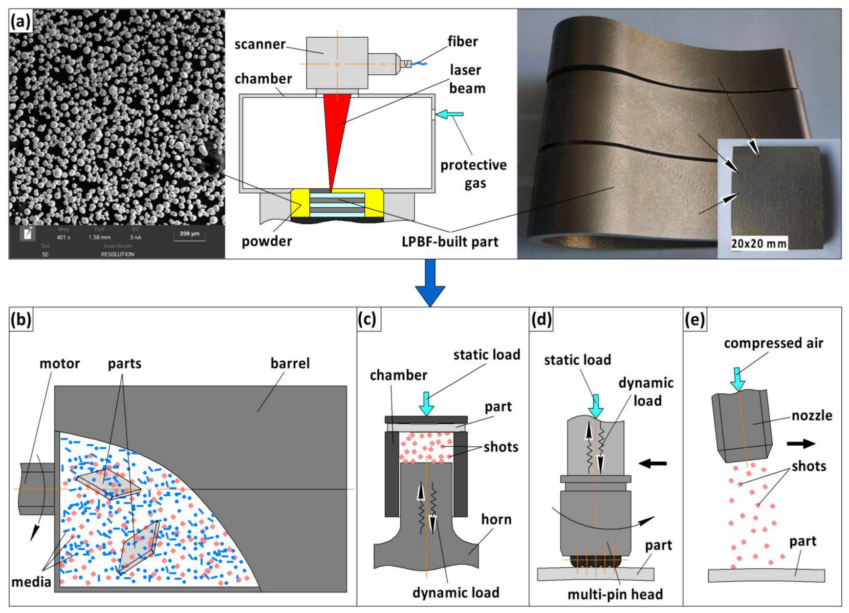
2.1. Specimen Additive Manufacturing

Turbine blade nickel-based alloy components were produced in this work by applying laser powder bed fusion 3D printing technology (Figure 1a) and a nickel-based pre-alloyed Inconel (IN) 718 metal powder (the nominal chemical composition (wt%) is 50–55% Ni, 17–21% Cr, 4.7–5.5% Nb, 2.8–3.3% Mo, 0.6–1.2% Ti, and 0.2–0.8% Al). The chemical composition of the LPBF-manufactured IN 718 alloy was found to be ~51.3% Ni, ~19% Cr, ~5.3% Nb, ~3.0% Mo, ~1.0% Ti, and ~0.5% Al. The correspondence of the chemical compositions of the powder and the fabricated IN 718 alloy meets the AMS 5663/ASTM B637 standard. Additionally, it should be emphasized that the size distribution of the spherical-shaped powder particles was registered to be in a range of 10 to 55 μm (Figure 1a). The powder had proper flowability according to the ASTM B213 and ASTM B964 specifications [39,40].
The turbine blade parts made from IN 718 were LPBF-produced using a Renishaw AM400 machine, which comprised scanning optics with a maximum scan speed and a maximum laser power of 7000 mm/s and 400 W (a ytterbium fiber laser), respectively (Figure 1a) [12,23,39]. A focused laser beam with a size of 70 μm on the substrate with a laser power of 200 W was used to melt the 60-μm-thick IN 718 powder layers at a scan speed of 700 mm/s according to a stripe pattern scanning strategy, alternating by an angle of 67° between build layers. The stripes’ distance was 5 mm, while the distance within fill hatch lines in every layer was 90 μm. The optimized LPBF parameters described above were used for the production of the IN 718 alloy parts. The continuous wave laser exposure mode was kept the same for all manufactured parts [12,41].
The LPBF-printed parts were removed from the building platform by electrical discharge machining (EDM). Firstly, the turbine blade test parts with base dimensions of approx. 85 mm × 60 mm were cut into three sections, which then were cut into samples of approx. 20 mm × 20 mm in size using EDM (Figure 1a). The sample preparation procedure is described in detail in [12].

2.2. Specimen Post-Processing

The LPBF-built samples with dimensions of approx. 3.5 mm × 20 mm × 20 mm underwent mechanical surface post-treatments (barrel finishing (BF), ultrasonic shot peening (USP), multi-pin ultrasonic impact treatment (UIT), and shot peening (SP) (Figure 1b)) to eliminate/reduce surface defects, enhancing surface integrity.
Barrel finishing (BF) was performed by equipment consisting of a horizontal hexagon barrel and a motor (Figure 1b) [12]. The barrel was filled up with LPBF-fabricated parts, metal shot media (steel burnishing balls 3.0 mm in diameter and a barrel filling ratio of 50%), and compounds. This high-energy finishing method consisted of motor-driven rotation of the barrel (rotation speed ~65 rpm) for 4 hrs. These BF parameters were empirically tailored for the surface treatment of LPBF-produced samples (Table 1).
The ultrasonic shot-peening (USP) process was carried out in a special vibrating chamber, which was filled with bearing balls of 3.5 mm in diameter (Figure 1c) [12]. The mechanical vibrations of the chamber were initiated by a piezo-electric ceramic transducer that converted an oscillating electric energy supplied by an ultrasonic generator with an 800 W power output and a frequency of 21.6 kHz. A step-like ultrasonic horn was used to amplify mechanical ultrasonic vibrations, which provided increased kinetic energy at an ultrasonic horn amplitude of 40 μm. The peening media acquired kinetic energy from contact with the horn tip vibration. Then, the peening media produced severe plastic deformation of the surface samples produced by LPBF. The distance between the surface sample and the horn tip surface was 40 mm. The USP treatment duration was set at 5 min (Table 1).
The multi-pin ultrasonic impact treatment (UIT) system, also known as high-frequency mechanical impact (HFMI) treatment, used an ultrasonic generator with an 800 W power output and a frequency of 21.6 kHz as the vibration supplier. Additionally, an ultrasonic vibration system was used that contained a piezo-electric ceramic transducer, a step-like horn, and a special multi-pin impact head guiding the cylindrical pins of 5 mm in diameter (Figure 1d) [42]. Forced rotation of the seven-pin impact head situated on the horn tip (rotation speed of 76 rpm) provided high-frequency impacts of ~1 kHz. The optimized multi-pin ultrasonic impact peening modes (amplitude of the ultrasonic horn 18 µm, treatment duration 120 s, and static load of the ultrasonic vibration system 50 N) [43,44] were used to treat the LPBF-fabricated IN 718 alloy samples (Table 1).
Shot peening (SP) post-processing was carried out using industrial equipment inducing severe surface plastic deformation of the parts by bombardment with AISI 52100 bearing steel shots of 0.5 mm in diameter from a distance between the nozzle and the part surface of 30 mm (Figure 1e). Steel shots were driven by compressed air with a pressure of 0.55 MPa [18]. To achieve full surface coverage, the samples were shot-peened for 2 min to achieve high-intensity SP conditions (Table 1) [15,22,44].
The accumulated energy values (ΣE, J/mm2) in the post-processed IN 718 alloy samples, which were estimated accounting for treatment duration, frequency of impact events, energy of the single impact load, and the treated surface area (Table 1), corresponded to the following order: BF (1.15 J/mm2) > USP (2.03 J/mm2) > SP (3.15 J/mm2) > UIT (4.2 J/mm2), providing different degrees of surface deformation. The accumulated energy values were defined and calculated for each surface plastic deformation method used, taking into account well-known techniques [12,45,46,47].

2.3. Specimen Characterization

The microstructure of the LPBF-fabricated and mechanically surface post-finished specimens was examined using a Leica MEF4A optical light microscope, a high-resolution TESCAN Mira 3 LMU scanning electron microscope (SEM), and a JEOL CX-II transmission electron microscope (TEM). X-ray diffraction (XRD) analysis of the LPBF-fabricated and post-processed (after the BF, USP, UIT, and SP) specimens was conducted using a Rigaku Ultima IV diffractometer with monochromatic CuKα radiation at 30 kV and 30 mA and a 2θ (20–120°) scanning speed of 2 °/min. The crystallite size and lattice microstrains were estimated using a Wiliamson–Hall approach and Scherrer’s equation, accounting for the CuKα wave length (λ) and parameter K = 0.9 for the assumed sphericity of grains [48]: β = (K λ/cosθ) + η tanθ. A sin2ψ standard-based technique and (311) γ-phase peaks were used to assess the residual macro-stresses induced by LPBF manufacturing and mechanical post-processing of the specimens’ surface.
Microhardness depth profiles (HV0.025) were registered using a Leica VMHT hardness tester with a Vickers indenter loaded at 25 g, while macrohardness values (HRC10) on the surface were recorded using a DIA-TESTOR 2Rc hardness tester with a load of 10 kg. The surface hardening intensity magnitudes (Ihard, %) of the untreated (HRCuntreated) and treated (HRCtreated) specimens were calculated using the following equation: Ihard = HRCtreated − HRCuntreated/HRCuntreated × 100%.
A Mitutoyo Hyper Quick Vision WLI 3D high-precision measuring system and a 3D Taylor Hobson Form Talysurf 120 surface profilometer were used to study the surface morphology (the selected area was about 500 × 500 µm2). The areal surface roughness (Sa, Sq, Sp, Sv, and Sz) and functional parameters (Sk, Spk, Svk, Sbi, Sci, Svi, Ssk, Vvv, Vvc, Vmc, and Vmp) were assessed [15,49]. The 3D parameters of the surface roughness were evaluated according to the specification standards ISO 25178-2:2012 and ISO 21920-2:2021.
The potentiodynamic polarization behaviors of the LPBF-fabricated and BF, SP, USP, and UIT post-processed IN 718 samples (the total area of each tested specimen was ~50 mm2) in a 3.5% NaCl solution were studied at room temperature.

3. Results and Discussions

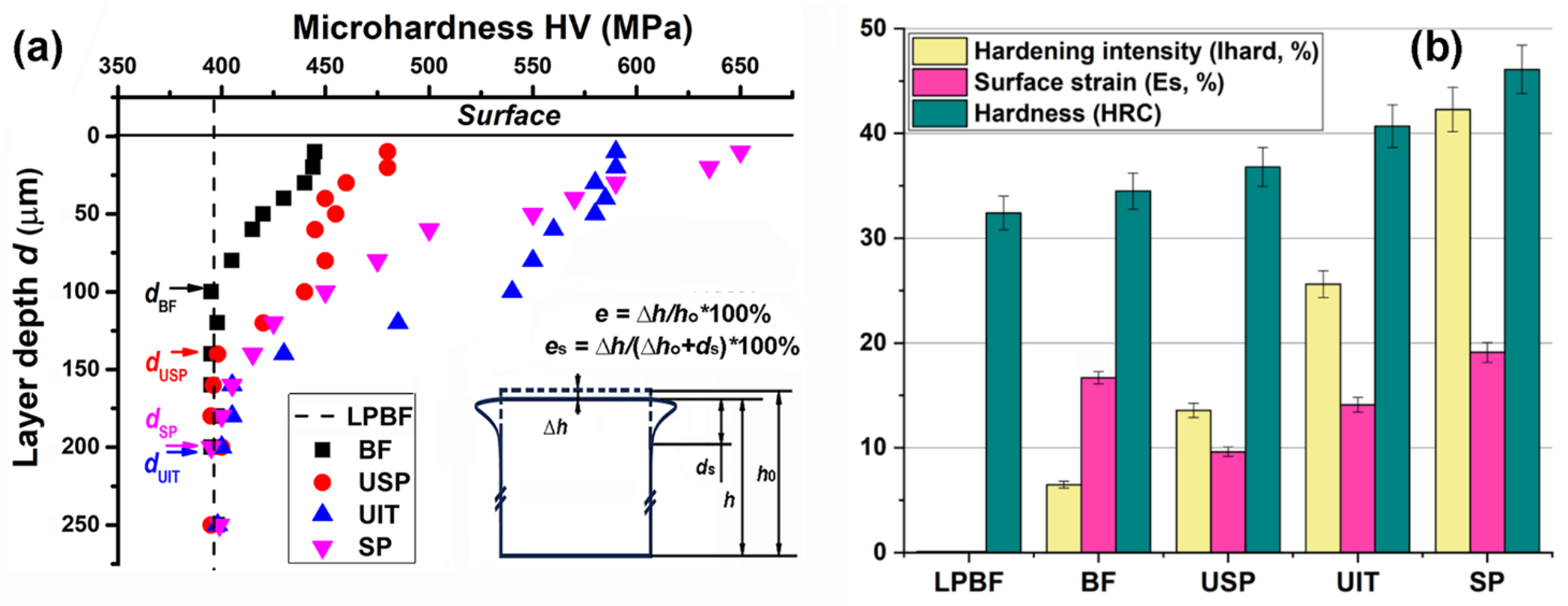
3.1. Surface Strain and Hardening Intensity

The applied mechanical surface treatments resulted in a slight reduction of specimen thickness in comparison with the LPBF-manufactured Ni-based alloy parts (Figure 2). The specimen thickness values after barrel finishing (BF), ultrasonic shot-peening (USP), shot-peening (SP), and multi-pin ultrasonic impact treatment (UIT) post-processing were 3.545 mm, 3.540 mm, 3.529 mm, and 3.519 mm, respectively. However, the strain was distributed unevenly with sample height, and the highest strain extent, highest strain rate, and highest hardening occurred in near-surface regions (Figure 3). Thus, near-surface strain was defined as the ratio of specimen thickness change (Δh) to the thickness of the deformed surface layer (hardening depth) (Δh + ds) after the applied mechanical surface post-processing techniques, using the equation shown in the inset in Figure 3a. Hardening depths were observed to be 100 μm, 140 μm, 200 μm, and 200 μm for BF, USP, UIT, and SP, respectively (Figure 3a). These values correlate to the surface hardening intensity and HV/HRC hardness of the studied alloys (Figure 3b).
The highest surface hardness was observed after the shot-peening method (~45 HRC10, ~650 HV0.025). The surface hardness observed in this study correlated well with the microhardness measured in the near-surface layers using the cross-section samples discussed below (Figure 3). Additionally, the macro-hardness (hardening intensity) correlated with the surface strain extent, which is known to induce an essential decrease in grain size down to the nano-scale [23,24,31,42,44].

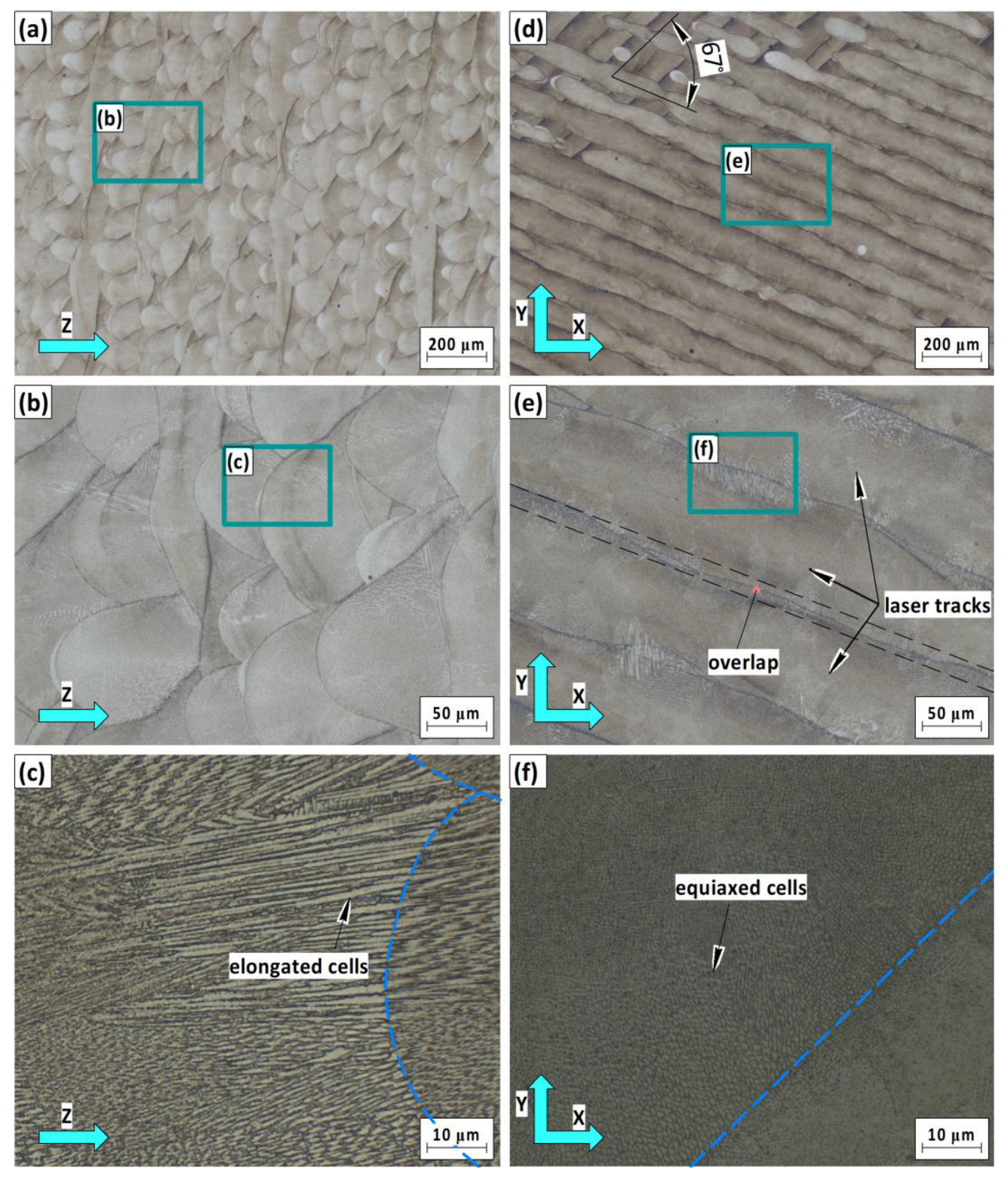
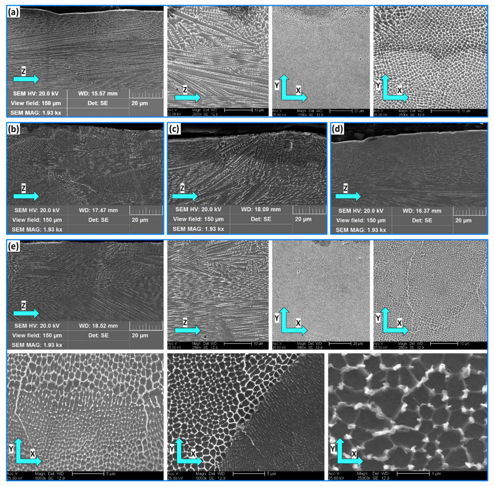
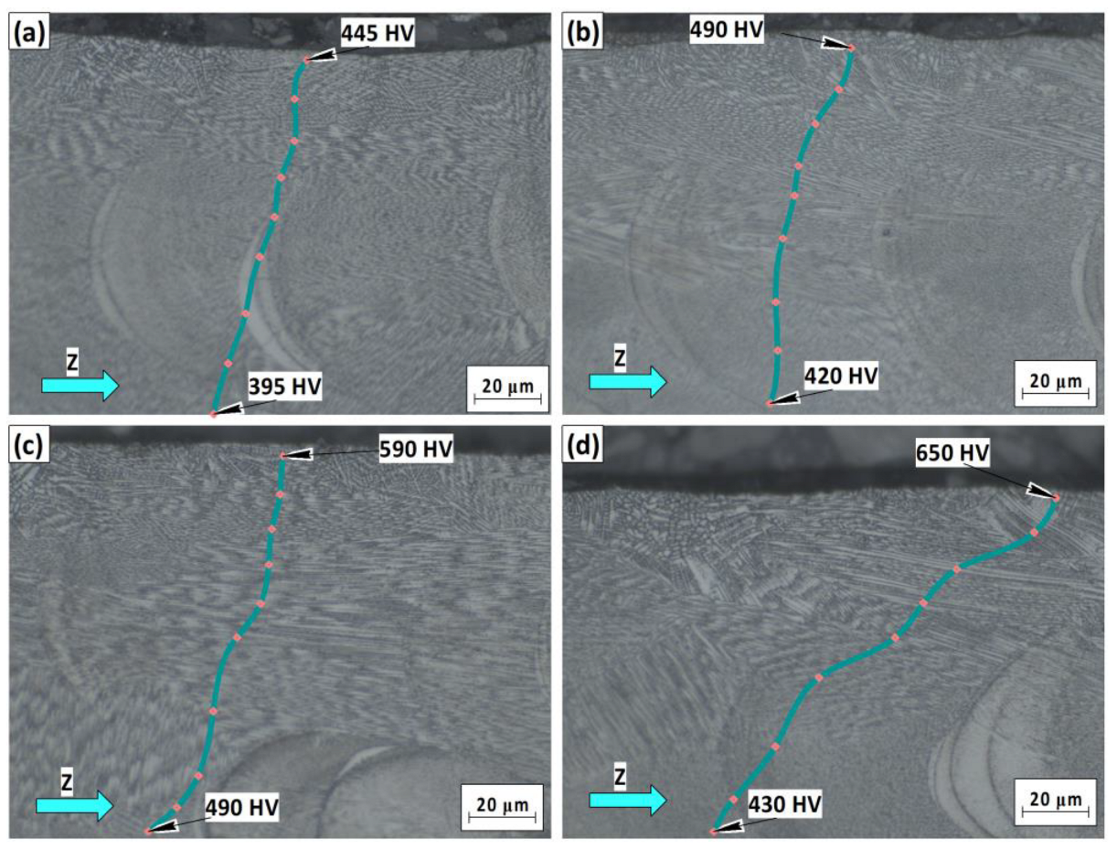
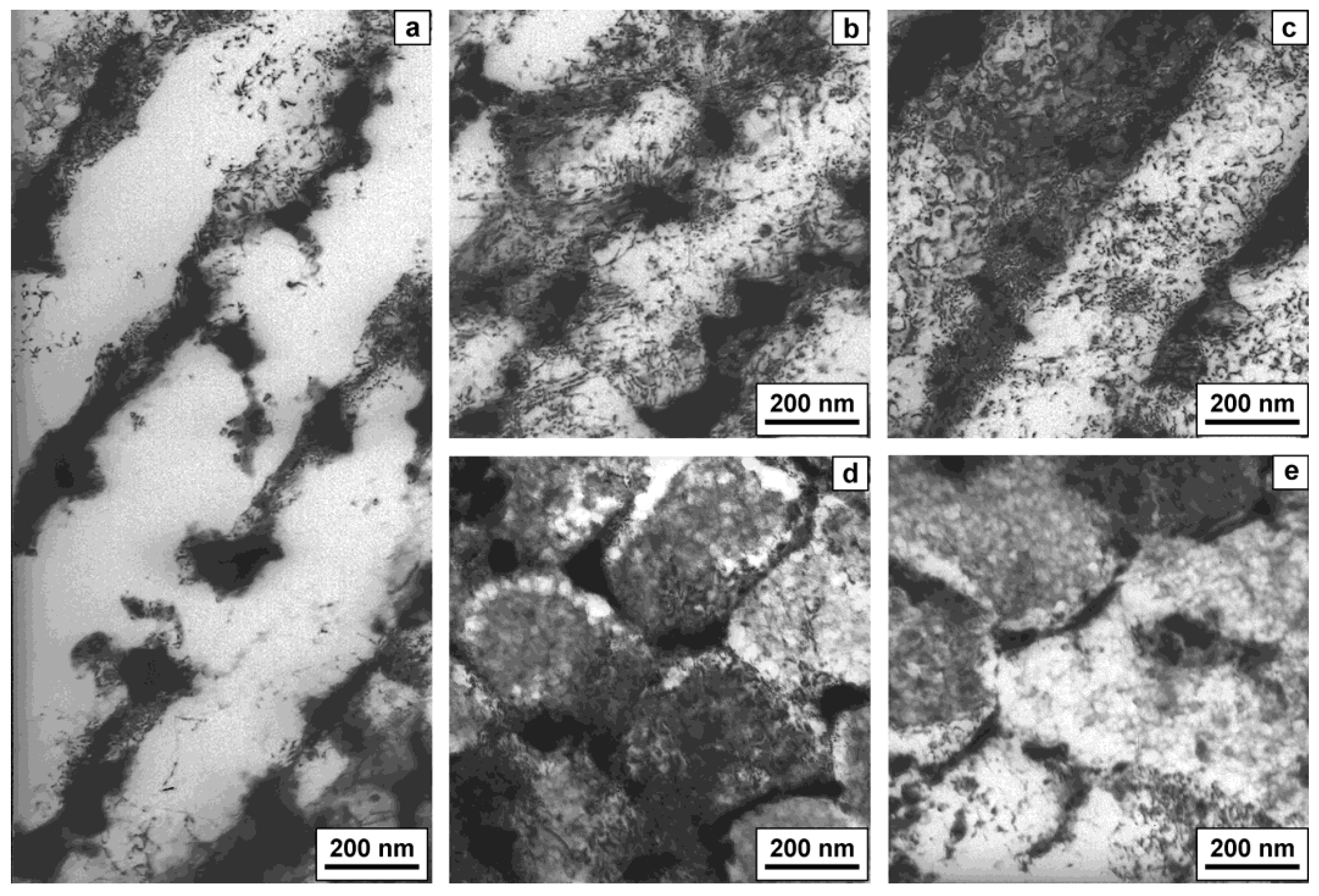
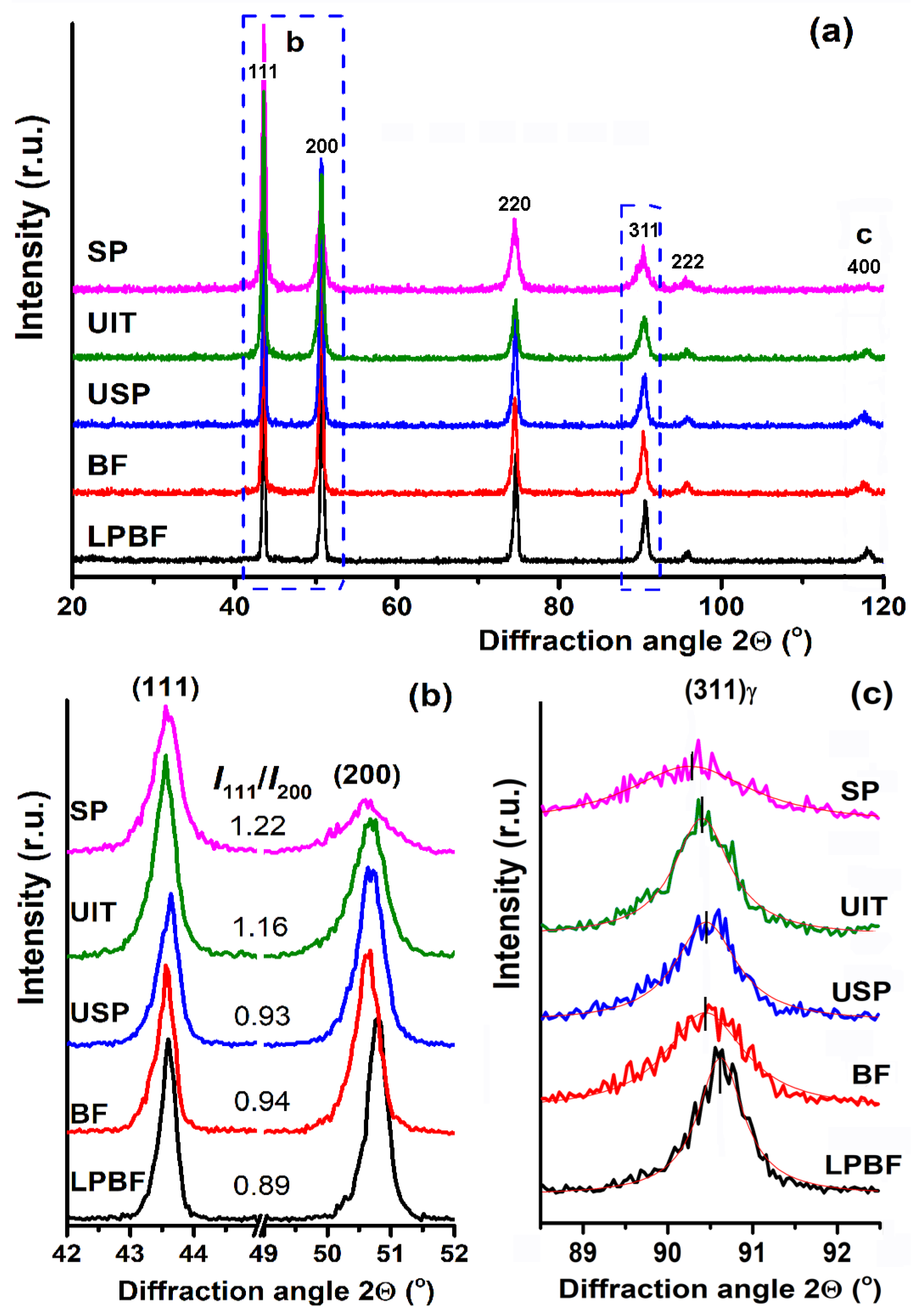
3.2. Microstructure and Microhardness

The subsurface microstructure, phase state, and hardness change of the LPBF-fabricated and barrel-finished, ultrasonically peened, and shot-peened IN 718 alloy parts were observed at the micrometric level using LOM (Figure 4) and SEM (Figure 5) and at the nanoscale using TEM (Figure 7), and XRD analysis was performed, to provide integral information regarding the structure-phase state of the outmost surface layer (Figure 8).
LOM images show the zones with melt pool laser tracks and microstructural features in the LPBF-built specimen cross-sections in the build (Figure 4a–c) and scan (Figure 4d–f) directions. The dendritic microstructure, with strong metallurgical bonding between adjacent laser melted layers, consists of elongated and equiaxed cells formed by sequential building of the part owing to rapid cooling (104–106 K/s) of the melt pool [1,3,8,50]. The dendritic microstructure in the growth direction comprises overlapped semicircular track patterns and mainly elongated colonies of cells across multiple build layers (Figure 4a,b and Figure 5a,e), which grow along the heat flow direction. Figure 4c and Figure 5a show fine columnar grains with interdendritic precipitated phases, which may provide higher corrosion resistance than coarser dendritic grains [51]. The scanning direction microstructure (X–Y cross-section plane) contains laser scanning tracks and transversely cut dendritic cells (Figure 4f and Figure 5a,e). Application of the selected LPBF process parameters [P = 200 W, V = 700 mm/s, h = 60 µm (powder layer)] resulted in a melt depth of 100–120 µm (Figure 4b).
As compared to the volume regions, the near-surface porosity of the LPBF-built IN 718 alloy sample was quite high (0.70% in the build direction) [12]. Spherical pores (gas pores) ranging from 1 to 50 μm were found in the near-surface regions, which were caused by incomplete gas release from the melt during the LPBF process. It should also be noted that a few small-sized aspherical pores (lack-of-fusion defects) were found, which usually form in the build direction due to insufficient penetration of the melt pool into the previous layer [34,52]. The general trend shows that the near-surface porosity was slightly higher when complexly-shaped components were produced by LPBF. Compared to the alloy produced by the conventional manufacturing process, the anti-corrosion performance of the LPBF-built IN 718 alloy was slightly deteriorated in a 3.5 wt.% sodium chloride solution due to the porous passive film formed on the LPBF sample, which had more NiO and less Cr2O3 [53]. At the same time, the LPBF-produced IN 718 superalloy specimens demonstrated better corrosion resistance due to the increased amount of the secondary δ phase precipitated on the grain boundaries of the wrought material [54]. The high roughness, surface defects, and subsurface porosity were the main factors promoting the formation of corrosion traces on the surface of the LPBF parts. To increase the material density near the surface and reduce the surface roughness, optimization of the laser beam toolpath in the context of contour/border scanning is in progress [55].
The SEM observations show that the microstructure of IN 718 alloy in the LPBF state consisted of randomly oriented dendritic columnar-shaped grains, carbides, and interdendritic precipitates, which were of various shapes, i.e., the disk-shaped γ||-phase, the spheroidal γ|-phase, the needle-like δ-phase, and the Laves phase, which appeared as bright islands and interlayers (Figure 4 and Figure 5). The observed formation and features of the structure of Inconel 718 alloy correlate well with literature data regarding heat-resistant alloys produced by the LPBF process [3,50,56].
The applied mechanical surface post-processing techniques, i.e., barrel finishing, ultrasonic, and shot peening, provided the gradual microhardness increase in the subsurface layer from the bulk to the outmost surface (see the blue lines in Figure 6). The near-surface microhardness magnitudes after BF, USP, UIT, and SP post-processing respectively achieved ~450 HV0.025, ~490 HV0.025, ~590 HV0.025, and ~650 HV0.025. The hardening depth after the treatment was ~100 μm, while USP treatment produced a deeper hardened layer (~140 μm). UIT and SP induced severe straining of the near-surface layer, providing a hardening depth of ~200 μm. Accordingly, the average values of subsurface porosity registered for the USP- and UIT-treated samples were lower than the porosity observed for the BF- or SP-treated ones. The near-surface residual porosity values were decreased by ~23%, ~41%, ~55%, and ~84% after the BF, SP, USP, and UIT post-processing techniques, respectively. A detailed study of porosity in IN 718 alloy samples after post-treatment was performed in [12,52]. The observed increase in the near-surface microhardness was associated with dislocation multiplications and rearrangements, accompanied by the formation of dislocation cell structure, which led to a reduction in a grain/subgrain size of the studied alloy. Both high dislocation density and dislocation cells can serve as effective strengthening factors.
This was confirmed by TEM analysis of the microstructure formed in the outmost surface layers, which were ~10–15 nm thick (Figure 7). The LPBF-built material consists of a dendritic (layered) structure of a Ni-based solid solution with an interdendritic area, consisting of the Laves phase and carbides (Figure 7a). It is evident in the bright-field TEM image that the matrix solid solution was almost free from dislocations, while their tangles were visible near the interdendritic interlayers. On the contrary, the microstructures of the mechanically post-processed samples became more dislocated. Despite the layered structure remaining predominant, the Laves phase interlayers become interrupted, and the dislocation tangles and bundles were often visible far away from the interlayers (Figure 7b,c). Additionally, at the higher strain induced by the ultrasonic impact peening and shot-peening methods, the initial grains transformed into submicronic ones (250–500 nm) and subdivided into nanoscale (15–30 nm) dislocation cells (Figure 7d,e). These observations are good explanations for the observed hardening. Moreover, high-density dislocations affecting lattice microstrains and dislocation cells (i.e., crystallites or coherent scattering areas (CSA)) are known to result in XRD peak broadening [48].
Indeed, the XRD analysis showed peak broadening and a shift to lower diffraction angles for the mechanically post-processed samples (Figure 8). According to the XRD peak broadening analysis, the CSA size values decreased to 25–30 nm after BF and USP and to 10–20 nm after UIT and SP, which correlate well with the TEM observations. The lattice microstrains in the BF, USP, UIT, and SP post-processed near-surface layers were evaluated to be 2 × 10⁻³, 3.2 × 10⁻³, 2.9 × 10⁻³, and 1.5 × 10⁻³, respectively. Based on the crystallite size (D) and the lattice microstrains (η) evaluated by XRD analysis and Burgers vector b (for Ni-based matrix b = 0.254 nm [57]), the dislocation density (ρ) magnitudes were estimated using the following formula [48]: ρ = (2 √3 η)/D b. The ascending trend of the assessed dislocation densities ρ correlated well with the TEM observations of the BF-, USP-, and UIT-processed samples, i.e., ρ increased from 8.05 × 10¹² m−2 to 1.15 × 10¹³ m−2 and 2.16 × 10¹³ m−2, respectively. Compared to the UIT-processed sample, the dislocation density ρ of the SP-processed sample was slightly lower (2.1 × 10¹³ m−2) due to the formation of smaller dislocation cells (higher volume fraction of cell boundaries) accompanied by elimination of dislocations with the opposite signs.
Figure 8b,c demonstrate the fragments of the XRD spectra, with two first peaks ((111) and (200)) and a later (311) peak. Importantly, the ratio of the (111) and (200) XRD peaks intensities (I111/I200) was analyzed for the studied specimens (Figure 8b). The I111/I200 ratio for the LPBF-built material did not match the tabular XRD peak intensity data for the face-centered cubic (FCC) lattice, indicating some crystallographic anisotropy with a surplus of the grains with the (200) plane oriented parallel to the specimen surface. The mechanical surface post-processing methods exerted different influences on the orientation of the surface grains. They either hardly affected it when the accumulated strain extent was relatively low (BF and USP techniques) or induced the grains’ reorientation at higher accumulated surface strains (UIT and SP techniques). In the latter case, the predominance of grains in the (111) plane oriented parallel to the sample surface were in line with the tabular intensity data for the FCC lattice, although to different extents. This is important in accounting for surface-related properties, such as wear, corrosion, and fatigue resistance.
The largest residual macro-stress values, which were recorded after the ultrasonic and shot-peening treatments, correlated well with the assessed surface layer strain magnitudes (Figure 2) and the accumulated impact energy (Table 1) for the post-processing methods [12]. According to the sin2ψ-based stress analysis of the (311) peaks, the near-surface compressive residual macro-stress values after BF, USP, UIT, and SP post-processing were about −200 MPa, −315 MPa, −430 MPa, and −510 MPa, respectively. Munther et al. [58] found that LSP-induced near-surface compressive residual macro-stresses (−590 MPa) at a depth of ~1 mm. Evidently, the UIT and SP methods induced the most severe plastic deformation, causing a greater increase in compressive residual stresses than BF and USP, but 15–25% lower than that after LSP. At the same time, the achieved microhardness values were larger after UIT and SP compared to that reported for a laser shock-peened IN 718 alloy manufactured by LPBF [58]. However, compared to the hardening depth reaching ~1 mm after the LSP process, it was significantly smaller for the studied alloy after the UIT and SP treatments (Figure 6).
The observed microstructural features significantly affected surface-related properties such as corrosion performance, as considered below. However, the positive effects of microstructural factors would remain at the forefront only if inappropriate surface microrelief does not mask them. Therefore, the functional characteristics of the surface morphology are analyzed in detail in the next section.

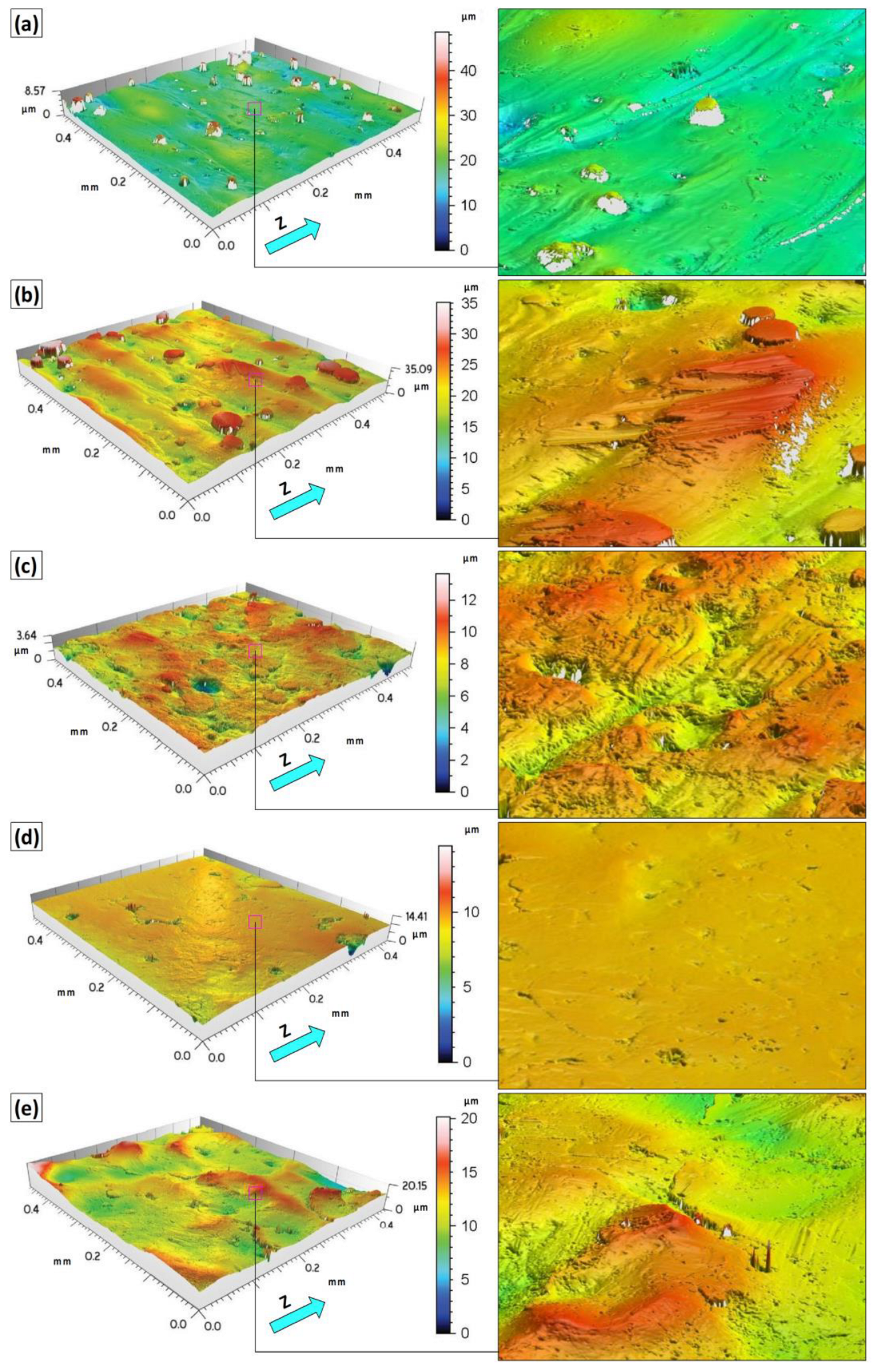
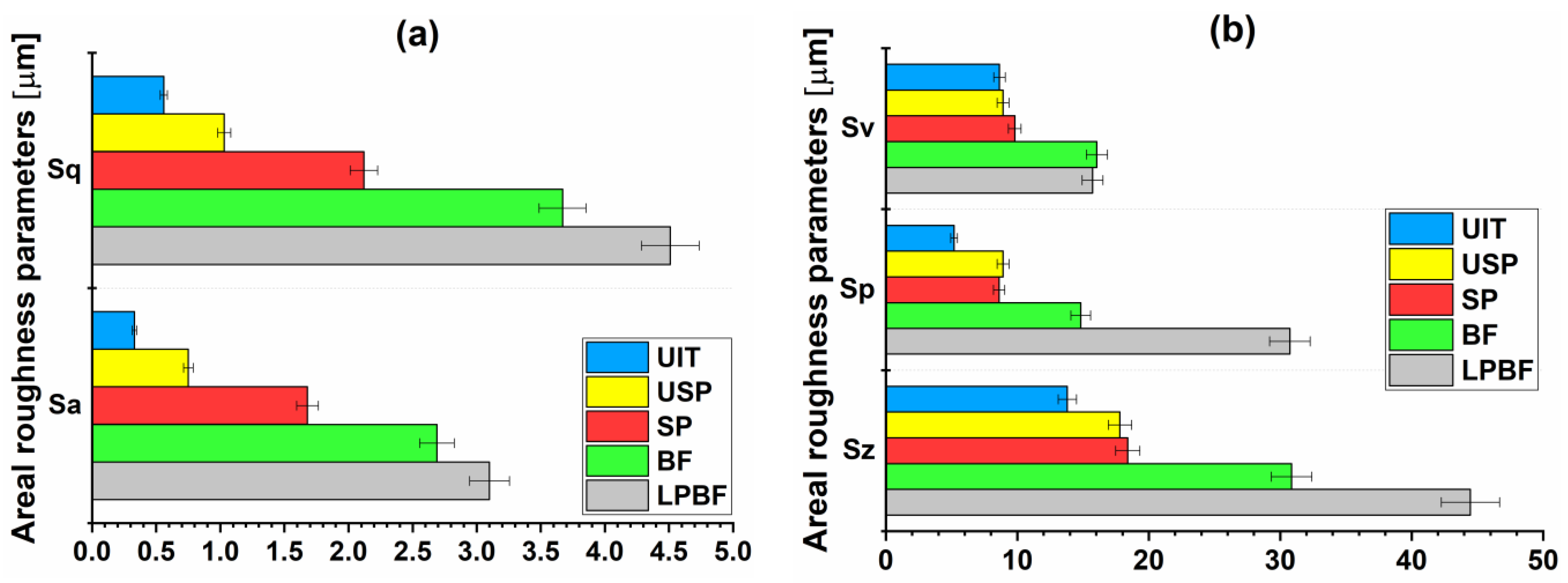
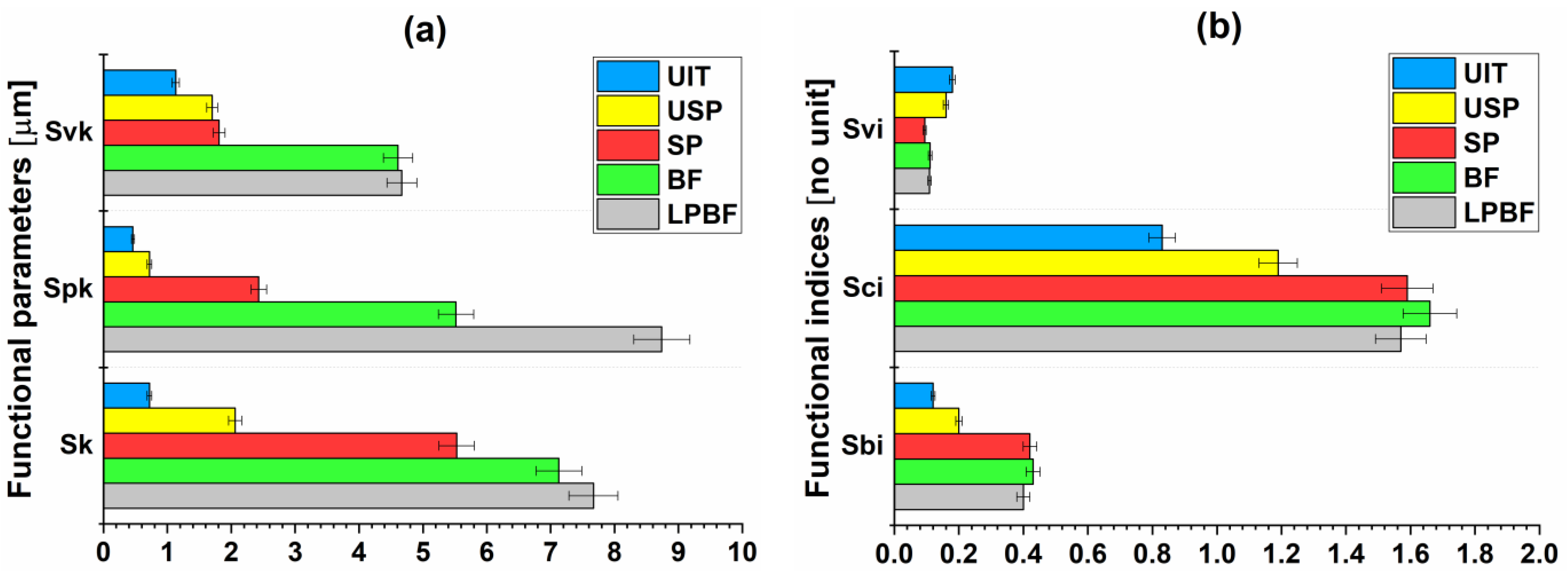
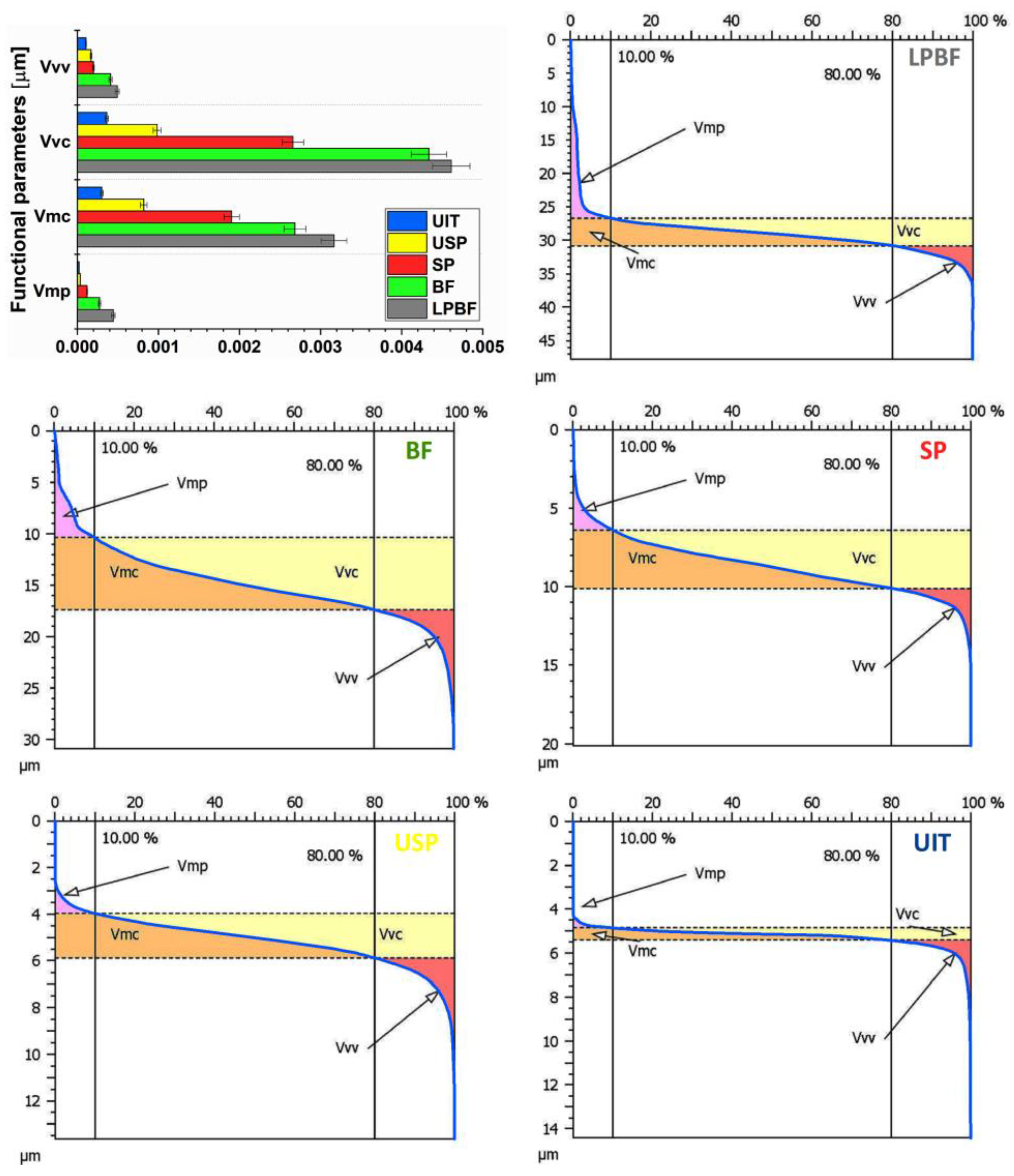
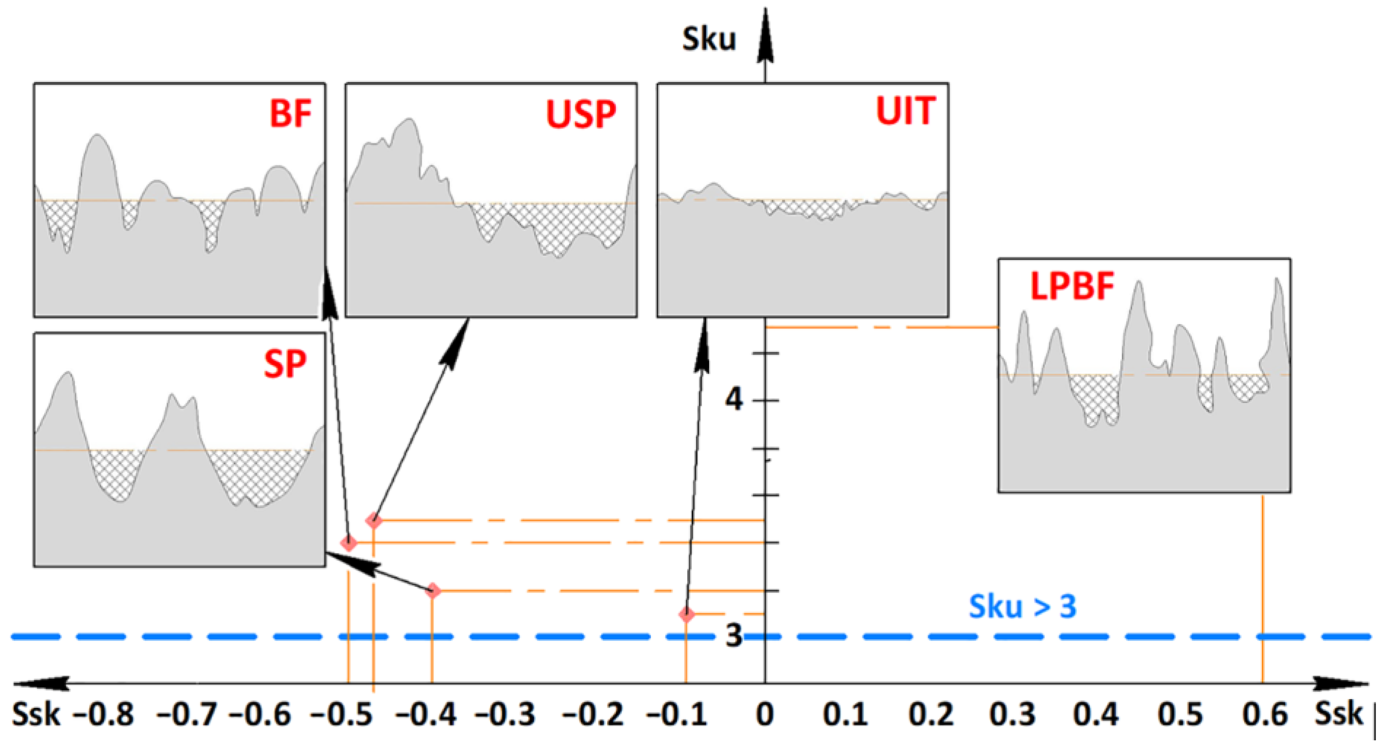
3.3. Surface Microrelief

Changes in the surface microrelief/texture of the LPBF-manufactured and mechanically surface post-processed IN 718 samples, as examined by confocal laser scanning microscope, are demonstrated in Figure 9. Generally, the areal roughness (Sa parameter) evaluated from a 500 × 500 µm2 area of laser powder bed–fused components was decreased by the surface finishing post-treatments that were applied. The microrelief formed on the sample surfaces by the mechanical surface treatments differed with regards to texturing and functionality-related properties, depending on the accumulated energy [ΣE, J/mm2]. The mechanically surface post-processed IN 718 alloy specimens (Figure 9b–e) exhibited a significant change in morphology after the multi-pin UIT (~4.2 J/mm2) and SP (~3.1 J/mm2) treatments. The USP (~2.0 J/mm2) and BF (~1.1) treatments lead to less severe plastic deformation, which correlated well with the process parameters and determined values of the accumulated energy (see Table 1). The roughness profile Sa and Sq parameters of the LPBF-manufactured and post-processed 718 alloy samples corresponded to the following order: UIT (~0.33 µm/~0.028 µm) > USP (~0.75 µm/~1.03 µm) > SP (~1.70 µm/~2.12 µm) > BF (~2.70 µm/~3.67 µm) > LPBF (~3.10 µm/~4.51 µm), related to the defined accumulated energy (Figure 10a).
The topographic characteristics confirm that the LPBF-fabricated nickel-based alloy turbine blade parts contained various manufacturing defects on the surface (Figure 9a). For the LPBF-fabricated parts, the maximum peak height Sp parameter and maximum height Sz parameter of 3D surface morphology/texture were ~30.75 µm (Figure 10a) and ~45 µm (Figure 10b), respectively. These obtained values correlate with literature data, which confirm the harmful effect of coarse roughness and surface defects on the corrosion performance of 3D-printed metal parts [44,53].
Compared to the laser powder bed–fused sample, BF treatment did not completely eliminate the ellipsoidal/spherical balls and particles of partially molten powder (Figure 9b). Signs of the laser passes were also present on the surface after BF. Nevertheless, the surface texture Sz parameter was reduced by about 42% after the finishing barrel process (Figure 10b). The upper peaks of the micro-irregularities were mainly deformed in the BF-processed sample, primarily due to the friction process. This is explained by the fact that the Sp parameter was reduced two-fold, while the Sv parameter remained the same as in the LPBF sample. The increased height of the greatest valley within the defined area (Sv = ~16.0 µm) obtained in the LPBF-fabricated and BF post-finished specimens (Figure 10b) could be a stress concentrator, affecting the fatigue limit and wear/corrosion resistance. Taking into account the results from this research, it is recommended to increase BF duration or apply BF after sandblasting. It has also recently been confirmed that the Ra parameter was reduced by ~30% on internal surfaces after a BF duration of 24 h [35]. Further increasing BF duration (48 and 96 h) resulted in a considerable decrease in roughness (Ra = 2.8 –3.5 µm) compared to the untreated internal surfaces (Ra = ~11 µm).
Severe plastic deformation by the USP (Figure 9c), UIT (Figure 9d), and SP (Figure 9e) techniques resulted in essential changes in surface morphology in comparison with the sample post-treated by BF. The surface microreliefs became completely new after application of the UIT and SP treatments. The SP, USP, and UIT processes resulted in a reduction of Sz parameters by more than half in comparison with the LPBF-fabricated sample (Figure 10b). The surface texture maximum height for the SP post-processed samples was in a range of 16 to 20 µm. The surface reliefs formed by the USP and SP treatments became dimpled (↑ Sp parameter), which was caused by plastic strain influenced by collisions of shots nearly perpendicular to the processed surface driven by the compressed air flow in relation to the SP treatment (Figure 9e). On the contrary, in relation to USP treatment (Figure 9c), the balls moved chaotically inside the container and influenced the processed surface at random angles [12]. Severe SP treatment increased the average surface roughness (Sa = ~1.68 µm) compared to USP treatment (Sa = ~0.75 µm). Such surface microreliefs formed by USP or SP can cause a reduction in wear and friction, as well as improve seizure resistance of sliding assemblies and oil retention capability [49,59]. The surface microreliefs and roughness parameters obtained after USP and SP treatments (Figure 10b) are consistent with previous works [24,44,60].
The surface roughness in the 3D-manufactured components was essentially decreased by multi-pin ultrasonic impact peening (Sa = ~0.3 µm, Sq = ~0.028 µm, Sp = ~0.26 µm, Sv = ~0.43 µm, Sz = ~0.69 µm) in comparison with the barrel finishing, ultrasonic shot-peening, and shot-peening treatments (Figure 10). This is primarily owing to shaping of a flattened microrelief on the surface through severe plastic deformation by the multi-pin head. The head with seven tips that was used induced both dynamic flattening of surface micro-inequalities and smoothing out of micro-irregularities, due to the synchronous rotation of the high-frequency impact head and the relative movement of the treated surface. These outcomes are also in good accordance with data from the literature [12,22,44].
Functional parameters based on the surface roughness/texture (Figure 11, Figure 12 and Figure 13) are important indicators that were also determined in order to estimate their impact on performance properties, including corrosion behavior [15,52]. As seen, the surface finishing techniques affect the Sk, Spk, and Svk bearing ratio parameters compared to the LPBF-built Inconel 718 alloy parts (Figure 11a). The surface-bearing contact area was increased after post-processing (Figure 12). Accounting for the surface-bearing contact area values, the post-processing of the surface finishing methods induced the formation more wear-resistant (Spk parameter) and exploitable (Sk parameter) surface textures in comparison with the LPBF-fabricated IN 718 alloy samples (Figure 12). The bearing material ratio parameters in relation to the Abbott–Firestone bearing curves were altered for the post-processed specimens: BF > SP > USP > UIT. This order corresponds to the functional indices (Figure 11b) and the volume parameters (Figure 12).
The above-discussed functional indices are useful for estimation of the influence of mechanically post-treated surface regions on surface contact (Svi parameter), lubrication (Sci parameter), and wear (Sbi parameter). The UIT (Sbi = ~0.12) and USP (Sbi = ~0.2) post-peened surfaces exhibited lower surface-bearing index values, which indicate greater wear resistance. On the contrary, the LPBF-manufactured, barrel-finished, and shot-peened surface samples (Sbi = ~0.4) exhibited less wear resistance than the 718 alloy, as reflected by the increased surface-bearing index values (Figure 11b). Considering the Svi parameter, the surface contact was considerably enhanced after the UIT post-processing technique.
Considering the Svk, Sci, and Vvv parameters, the lubricant reserve was different depending on the mechanical surface post-processing technique (Figure 11 and Figure 12). A higher lubricant reserve was observed after the USP, SP, and BF treatments than after the UIT treatment. Thus, the ultrasonic peening process formed smooth wavy surfaces (Sa = ~0.5 µm), while the shot-peening process caused a rougher wavy surface (Sa = ~1.5 µm). The surface was the roughest after the BF process (Sa = ~2.5 µm). As a consequence, the ultrasonically post-finished surfaces are expected to be more resistant to wear and corrosion, taking into account that the fatigue life and corrosion resistance of LPBF-printed metallic components are increased with a reduction in roughness height.
Characterization of the surface microrelief in relation to corrosion and tribological performance (skewness–kurtosis areal surface roughness Ssk–Sku parameters characterize the aspect of the texture height distribution (Figure 13)) indicated that the LPBF sample contained a large number of peaks on the surface (Ssk = 0.6 µm) as a consequence of the presence of manufacturing surface defects. A positive Ssk magnitude indicates a prevalence of heights on the surface, while a negative Ssk magnitude indicates a large amount of pits on the surface [49]. Additionally, the appearance of manufacturing surface defects during LPBF led to a slight increase Sku parameter, demonstrating the presence of sharp peaks (Figure 13) [52]. Deep corrosion attacks are caused by the flat distribution with low kurtosis (Rku < 3) [61]. These results indicate that the LPBF samples may be sensitive to pitting corrosion (Rku > 3) [62]. Unlike the LPBF-built IN 718 alloy specimens, the application of the surface finishing methods resulted in kurtosis Sku values close to 3, forming more uniform microreliefs on the surface with uniform heights of the peaks and valleys. The Ssk parameter values decreased towards smaller/negative values (reduction of sharp peaks on the surface) after the surface finishing methods were applied (Figure 13) [52]. It is expected that the smooth surface of the UIT-processed samples can improve both wear and corrosion resistance, because the Ssk parameter was close to 0, indicating that the peaks and valleys were evenly spread. Compared to the UIT-processed sample, the SP- and USP-peened samples were characterized by a greater number of deeper pits on the surface (Figure 13). Additionally, compared to the LPBF specimen, the surface peaks were truncated after post-processing, indicating negative magnitudes of the Ssk parameter.
The skewness–kurtosis indicators and areal material ratio are effective for analyzing surface texture in relation to tribological behavior. Considering the corrosion types assessed by kurtosis and skewness areal surface roughness parameters [62], it is expected that untreated and mechanically surface post-treated superalloy samples will be more resistant to uniform corrosion and transgranular/intergranular stress corrosion cracking, but that localized corrosion may appear faster in LPBF and BF specimens compared to SP, USP, and UIT post-finished specimens. Comprehensive assessment of the corrosion resistance and microstructure/hardening intensity (Figure 3) of the surface layer coupled with the surface microrelief/roughness (Figure 9 and Figure 10) parameters was implemented to predict the uniform corrosion (Ccorr) of the studied IN 718 superalloy specimens:
C corr = ( 1.1 I hard 4 + 4 I hard 3 4.1 I hard 2 ) × 28 × 1 0 6 R v t m 2 × S m 2 2 / 3
where Ihard is the hardening intensity of the surface layer [%], Rv is the maximum profile valley depth, which shows the extent of the lowest point of the surface profile about the mean line at the assessment time [μm], tm is the exploitation zone, which shows the relative reference length of the surface roughness profile at the mean line [%], and Sm is the mean width of the roughness profile elements/micro-irregularities [mm].
Theoretical assessment of corrosion resistance according to the above-mentioned complex indicators showed that the calculated corrosion resistance values of the BF, USP, SP, and UIT post-processed IN 718 alloy samples were 1.497 × 10⁸, 2.565 × 10⁹, 2.397 × 10¹⁰, and 4.735 × 10¹¹, respectively. Compared to the LPBF-built sample (Ccorr = 3.616 × 10⁴), the corrosion resistance increased irrespective of the surface finishing method used. Thus, the surface microrelief (surface defects and roughness) and functionality-related properties, supplemented with the surface microstructure (grain morphology and size, phase composition, and subsurface porosity), are the key characteristics of the surface quality/integrity of metallic parts produced by LPBF.

3.4. Corrosion Resistance Behavior

The corrosion behaviors of the LPBF-printed and BF, USP, SP, and UIT mechanically post-treated IN 718 alloy samples were analyzed in the form of potentiodynamic polarization curves, as shown in Figure 14. It is evident that the polarization curves of the LPBF-fabricated samples mechanically surface post-treated using the BF (curve 2), USP (curve 3), SP (curve 4), and UIT (curve 5) methods exhibited larger potentials (E) and lower corrosion densities. These observations confirm that the mechanically surface-treated samples corroded far more gradually than the LPBF-fabricated sample. Compared to the BF (Ecorr = –296 mV) and USP (Ecorr = −291 mV) treatments, the SP and UIT treatments increased the corrosion potential. The corrosion potential values were –199 mV and –197 mV after SP and UIT treatment, respectively. These tendencies also are in good agreement with the theoretical assessment of corrosion resistance (Ccorr) of the studied alloy estimated by Formula (1).
The SP and UIT mechanically post-processed samples exhibited lower passivation current values in comparison with the BF and USP post-processed samples. Additionally, the pitting initiation rate magnitudes were also lower after SP/UT treatment than those for LPBF-fabricated and BF/USP-treated samples [52]. Compared to the BF and USP techniques, the greater improvement in corrosion behavior seen after UIT and SP was because of the lower magnitudes of residual porosity in the near-surface layer, the crystallite size, and the surface roughness values (Figure 15). The average surface roughness (Figure 7) and residual porosity [12] were significantly reduced by UIT treatment, while the average crystallite size (Figure 15) and hardening intensity (Figure 6) were remarkably increased by the shot-peening method. The average surface roughness parameters of the SP-peened specimens were similar to the roughness values provided by sandblasting of LPBF-manufactured Inconel 718 alloy plane samples [58].
The corrosion rate estimated to confirm Faraday’s law [52] was in good agreement with the averaged grain size and surface roughness (Figure 15). BF and USP significantly decreased the corrosion rates (~16.0 and ~14.0 μm/year, respectively) as compared to the LPBF-fabricated IN718 alloy sample (~45.0 μm/year). In the case of the UIT and SP post-peened samples, the corrosion rates were observed to be lowest (5.47 and 6.56 μm/year, respectively). Compared with UIT treatment, the corrosion rate was slightly increased after SP treatment due to the higher surface roughness. SP treatment was shown to be an effective tool for eliminating surface defects on the LPBF-manufactured surface parts, reducing the roughness [15,44] but increasing the waviness [63]. Multi-pin ultrasonic surface peening was the most efficient method for enhancing corrosion resistance among the mechanical surface post-processing techniques studied due to a significant reduction in roughness and porosity [64]. This was primarily owing to the formation of a flattened surface microrelief with low roughness/porosity and significant refinement of structural components in the near-surface layer (Figure 15). The ultrafine-grained structure with a large fraction of grain boundaries that formed facilitates quick corrosion and oxide layer formation in the first stage of corrosion attack, and the oxide film/layer becomes an effective protector against further corrosion degradation of the modified surfaces [65,66,67,68,69].
Additionally, the UIT- and SP-induced reorientation of grains/subgrains had a favorable impact on anti-corrosion performance, since a fraction of the grains with (111) plains parallel to the sample surface was higher. Grains/subgrains in this orientation are known to be prone to the formation of so-called special boundaries, i.e., coincide site lattice (CSL) boundaries, which are more resistant to corrosion attack than boundaries of other types [70,71]. Grain boundary engineering can often improve the corrosion behavior of metallic materials, including Ni-based superalloys [72,73,74,75].

4. Conclusions

In this work, various advanced mechanical surface processing techniques were used to enhance the surface-related features of an Inconel 718 heat-resistant superalloy manufactured by LPBF technology. The strain-induced surface relief shallowing and grain size decrease were concluded to be the main factors affecting the hardening and enhanced anti-corrosion behavior of the peened surfaces. The efficiency of the post-processing methods used can be arranged in the following ascending sequence: BF, USP, and UIT/SP. The appropriate surface finishing method may be selected based on the surface specification (surface roughness, subsurface grain size, hardening/compressive macro-stress formation, and modified layer thickness) and shape/dimensions of the component to be processed. BF post-processing can be used predominantly for surface finishing of complex LPBF-manufactured 718 superalloy end-products (Ihard = ~6.5%, hd = 100 µm, D = ~34 nm, RS = −200 MPa, Sa = 2.68 µm). USP post-processing (Ihard = ~13.5%, hd = 140 µm, D = ~23 nm, RS = −315 MPa, Sa = 0.75 µm) is rather controllable and versatile, but USP may be applied for surface finishing and hardening of LPBF-fabricated small-scale/complexly shaped parts only. In contrast, multi-pin UIT post-processing (Ihard = ~25.5%, D = ~15 nm, hd = 200 µm, RS = −430 MPa, Sa = 0.33 µm) can be recommended for the surface post-treatment of LPBF-fabricated large-sized products with simple geometries. SP post-processing (Ihard = ~42%, hd = 200 µm, D = ~10 nm, RS = −510 MPa, Sa = 1.68 µm) is an efficient post-processing method (corrosion rates are almost seven times lower after the SP process in contrast with the LPBF-produced IN 718 alloy sample) that can be applied for surface finishing of both large and small LPBF-fabricated structures.

Author Contributions

Conceptualization, D.L., B.M., S.M. and V.D.; data curation, D.L., B.M., S.M., D.G. and A.K.; formal analysis, D.L., B.M. and S.M.; funding acquisition, D.L., B.M., V.D. and A.L.; investigation, D.L., B.M., S.M., D.G. and A.K.; methodology, D.L., B.M., S.M., V.D. and A.L.; project administration, D.L., B.M., V.D. and A.L.; resources, V.D. and A.L.; software, S.M.; supervision, V.D. and A.L.; validation, D.L., B.M., D.G. and A.K.; visualization, D.L. and B.M.; writing—original draft preparation, D.L. and B.M.; writing—review and editing, D.L., B.M., S.M., V.D. and A.L. All authors have read and agreed to the published version of the manuscript.

Funding

The authors gratefully acknowledge the support of the European Union’s HORIZON 2020 Research and Innovation Programme under the Marie Sklodowska-Curie Grant (agreement No. 101034379) and the National Research Foundation of Ukraine under the Science for the Recovery of Ukraine in the War and Post-War Periods Grant (agreement No. 2022.01/0038). This study was partially supported by the Basque Government (grants No. KK 2024/00018 and KK-2022/00070) and Grant TED2021-130543B-I00 funded by the MCIN/AEI/10.13039/501100011033 and the European Union Next Generation EU/PRTR. We also acknowledge the National Academy of Sciences of Ukraine (agreement No. 0123U102368).

Institutional Review Board Statement

Not applicable.

Informed Consent Statement

Not applicable.

Data Availability Statement

Datasets are available from the corresponding author upon reasonable request.

Acknowledgments

The Aeronautics Advanced Manufacturing Center of the University of the Basque Country (UPV/EHU) is gratefully acknowledged.

Conflicts of Interest

The authors declare no conflicts of interest.

Abbreviations

The following abbreviations are used in this manuscript:
BFBarrel finishing
CSACoherent scattering areas
CSLCoincide site lattice
DMLSDirect metal laser sintering
EBMElectron beam melting
EDMElectrical discharge machining
FCCFace-centered cubic
HFMIHigh-frequency mechanical impact
HRCHardness Rockwell C
HVHardness Vickers
LMDLaser metal deposition
LOMLight optical microscopy
LPBFLaser powder bed fusion
SEMScanning electron microscopy
SLMSelective laser melting
SPShot peening
TEMTransmission electron microscopy
UITUltrasonic impact treatment
USPUltrasonic shot peening
XRDX-ray diffraction

References

  1. Volpato, G.M.; Tetzlaff, U.; Fredel, M.C. A comprehensive literature review on laser powder bed fusion of Inconel superalloys. Addit. Manuf. 2022, 55, 102871. [Google Scholar] [CrossRef]
  2. Frazier, W.E. Metal additive manufacturing: A review. J. Mater. Eng. Perform. 2014, 23, 1917–1928. [Google Scholar] [CrossRef]
  3. Karia, M.C.; Popat, M.A.; Sangani, K.B. Selective laser melting of Inconel super alloy—A review. AIP Conf. Proc. 2017, 1859, 020013–020020. [Google Scholar] [CrossRef]
  4. Bambach, M.; Sizova, I.; Kies, F.; Haase, C. Directed energy deposition of Inconel 718 powder, cold and hot wire using a six-beam direct diode laser set-up. Addit. Manuf. 2021, 47, 102269. [Google Scholar] [CrossRef]
  5. Zhu, L.; Xue, P.; Lan, Q.; Meng, G.; Ren, Y.; Yang, Z.; Xu, P.; Liu, Z. Recent research and development status of laser cladding: A review. Opt. Laser Technol. 2021, 138, 106915. [Google Scholar] [CrossRef]
  6. Scendo, M.; Staszewska-Samson, K.; Danielewski, H. Corrosion behavior of Inconel 625 coating produced by laser cladding. Coatings 2021, 11, 759. [Google Scholar] [CrossRef]
  7. Venturi, F.; Taylor, R. Additive manufacturing in the context of repeatability and reliability. J. Mater. Eng. Perform. 2023, 32, 6589–6609. [Google Scholar] [CrossRef]
  8. Taghian, M.; Mosallanejad, M.H.; Lannunziata, E.; Del Greco, G.; Iuliano, L.; Saboori, A. Laser powder bed fusion of metallic components: Latest progress in productivity, quality, and cost perspectives. J. Mater. Res. Technol. 2023, 27, 6484–6500. [Google Scholar] [CrossRef]
  9. Kan, W.H.; Chiu, L.N.S.; Lim, C.V.S.; Zhu, Y.; Tian, Y.; Jiang, D.; Huang, A. A critical review on the effects of process-induced porosity on the mechanical properties of alloys fabricated by laser powder bed fusion. J. Mater. Sci. 2022, 57, 9818–9865. [Google Scholar] [CrossRef]
  10. Song, L.; Zeng, G.; Xiao, H.; Xiao, X.; Li, S. Repair of 304 stainless steel by laser cladding with 316L stainless steel powders followed by laser surface alloying with WC powders. J. Manuf. Process. 2016, 24, 116–124. [Google Scholar] [CrossRef]
  11. Sanchez, S.; Smith, P.; Xu, Z.; Gaspard, G.; Hyde, C.J.; Wits, W.W.; Ashcroft, I.A.; Chen, H.; Clare, A.T. Powder bed fusion of nickel-based superalloys: A review. Int. J. Mach. Tools Manuf. 2021, 165, 103729. [Google Scholar] [CrossRef]
  12. Lesyk, D.A.; Martinez, S.; Mordyuk, B.N.; Dzhemelinskyi, V.V.; Lamikiz, A.; Prokopenko, G.I. Post-processing of the Inconel 718 alloy parts fabricated by selective laser melting: Effects of mechanical surface treatments on surface topography, porosity, hardness and residual stress. Surf. Coat. Technol. 2020, 381, 125136. [Google Scholar] [CrossRef]
  13. Lesyk, D.A.; Martinez, S.; Dzhemelinskyi, V.V.; Stamann, O.; Mordyuk, B.N.; Lamikiz, A. Surface polishing of laser powder bed fused superalloy components by magnetic post-treatment. In Proceedings of the NAP 2020, Sumy, Ukraine, 9–13 November 2020; pp. 02SAMA17-1–02SAMA17-4. [Google Scholar] [CrossRef]
  14. Osoba, L.O.; Oladoye, A.M.; Ogbonna, V.E. Corrosion evaluation of superalloys Haynes and Inconel 718 in hydrochloric acid. J. Alloys Compd. 2019, 804, 376–384. [Google Scholar] [CrossRef]
  15. Lesyk, D.A.; Martinez, S.; Mordyuk, B.N.; Grochala, D.; Lamikiz, A. Functionality-related performance of surface microrelief evaluation in ultrasonically and shot peened Inconel 718 alloy manufactured by laser powder bed fusion process. In New Technologies, Development and Application VII. NT 2024; Lecture Notes in Networks and Systems; Karabegović, I., Ed.; Springer: Cham, Switzerland, 2025; Volume 1069, pp. 201–211. [Google Scholar] [CrossRef]
  16. Thiede, T.; Cabeza, S.; Mishurova, T.; Kromm, A.; Bode, J.; Haberland, C.; Bruno, G. Residual stress in selective laser melted Inconel 718: Influence of the removal from base plate and deposition hatch length. Mater. Perform. Character. 2017, 7, 0119–0138. [Google Scholar] [CrossRef]
  17. Fardan, A.; Klement, U.; Brodin, H.; Hryna, E. Effect of part thickness and build angle on the microstructure, surface roughness, and mechanical properties of additively manufactured IN-939. Metall. Mater. Trans. A 2023, 54, 1792–1807. [Google Scholar] [CrossRef]
  18. Koutiri, I.; EPessard, E.; Peyre, P.; Amlou, O.; De Terris, T. Influence of SLM process parameters on the surface finish, porosity rate and fatigue behavior of as-built Inconel 625 parts. J. Mater. Process. Technol. 2018, 255, 536–546. [Google Scholar] [CrossRef]
  19. Calignano, F.; Minetola, P. Influence of process parameters on the porosity, accuracy, roughness, and support structures of hastelloy X produced by laser powder bed fusion. Materials 2019, 12, 3178. [Google Scholar] [CrossRef]
  20. Sun, W.; Ma, Y.; Li, P.; Zhang, W. Residual stress distribution and Its effect on fatigue crack path of laser powder bed fusion Ti6Al4V alloy. Aerospace 2025, 12, 103. [Google Scholar] [CrossRef]
  21. Witkin, D.B.; Patel, D.N.; Helvajian, H.; Steffeney, L.; Diaz, A. Surface treatment of powder-bed fusion additive manufactured metals for improved fatigue life. J. Mater. Eng. Perform. 2019, 28, 681–692. [Google Scholar] [CrossRef]
  22. Lesyk, D.A.; Dzhemelinskyi, V.V.; Martinez, S.; Grzesiak, D.; Mordyuk, B.N. Functional evaluation of surface texture in laser selective melted Inconel 718 alloy parts processed by shot peening. In Advanced Manufacturing Processes IV; Tonkonogyi, V., Ed.; InterPartner 2022; Lecture Notes in Mechanical Engineering; Springer: Cham, Switzerland, 2023; pp. 294–305. [Google Scholar] [CrossRef]
  23. Lesyk, D.A.; Martinez, S.; Pedash, O.O.; Mordyuk, B.N.; Dzhemelinskyi, V.V.; Lamikiz, A. Nickel superalloy turbine blade parts printed by laser powder bed fusion: Thermo-mechanical post-processing for enhanced surface integrity and precipitation strengthening. J. Mater. Eng. Perform. 2022, 31, 6283–6299. [Google Scholar] [CrossRef]
  24. Maleki, E.; Unal, O.; Guagliano, M.; Bagherifard, S. The effects of shot peening, laser shock peening and ultrasonic nanocrystal surface modification on the fatigue strength of Inconel 718. Mater. Sci. Eng. A 2021, 810, 141029. [Google Scholar] [CrossRef]
  25. Kumar, H.; Singh, G. Parametric studies on finishing of inconel 718 flat surfaces with chemically assisted magnetic abrasive finishing process. Mater. Today Proc. 2021, 37, 3262–3269. [Google Scholar] [CrossRef]
  26. Mohammadian, N.; Turenne, S.; Brailovsk, V. Surface finish control of additively-manufactured Inconel 625 components using combined chemical-abrasive flow polishing. J. Mater. Process Technol. 2018, 252, 728–738. [Google Scholar] [CrossRef]
  27. Trdan, U.; Hocevar, M.; Gregorcic, P. Transition from superhydrophilic to superhydrophobic state of laser textured stainless steel surface and its effect on corrosion resistance. Corros. Sci. 2017, 123, 21–26. [Google Scholar] [CrossRef]
  28. Obeidi, M.A.; Conway, A.; Mussatto, A.; Dogu, M.N.; Sreenilayam, S.P.; Ayu, H.; Ahad, I.U.; Brabazon, D. Effects of powder compression and laser re-melting on the microstructure and mechanical properties of additively manufactured parts in laser-powder bed fusion. Results Mater. 2022, 13, 100264. [Google Scholar] [CrossRef]
  29. Metelkova, J.; Vanmunster, L.; Haitjema, H.; Ordnung, D.; Kruth, J.-P.; Van Hooreweder, B. Hybrid dual laser processing for improved quality of inclined up-facing surfaces in laser powder bed fusion of metals. J. Mater. Process. Technol. 2021, 298, 117263. [Google Scholar] [CrossRef]
  30. Balantič, D.A.S.; Donik, Č.; Podgornik, B.; Kocijan, A.; Godec, M. Improving the surface properties of additive-manufactured Inconel 625 by plasma nitriding. Surf. Coat. Technol. 2023, 452, 129130. [Google Scholar] [CrossRef]
  31. Karimbaev, R.M.; Cho, I.S.; Pyun, Y.S.; Amanov, A. Effect of ultrasonic nanocrystal surface modification treatment at room and high temperatures on the high-frequency fatigue behavior of Inconel 718 fabricated by laser metal deposition. Metals 2022, 12, 515. [Google Scholar] [CrossRef]
  32. Lee, S.J.; Shao, S.; Wells, D.N.; Zetek, M.; Kepka, M.; Shamsaei, N. Fatigue behavior and modeling of additively manufactured IN718: The effect of surface treatments and surface measurement techniques. J. Mater. Process. Technol. 2022, 302, 117475. [Google Scholar] [CrossRef]
  33. Karabulut, Y.; Kaynak, Y.; Sharif, S.; Suhaimi, M.A. Effect of machining and drag finishing on the surface integrity and mechanical properties of Inconel 718 alloys fabricated by laser powder bed fusion additive manufacturing. Mater. Sci. Eng. Technol. 2022, 53, 109–118. [Google Scholar] [CrossRef]
  34. Boschetto, A.; Bottini, L.; Macera, L.; Veniali, F. Post-processing of complex SLM parts by barrel finishing. Appl. Sci. 2020, 10, 1382. [Google Scholar] [CrossRef]
  35. Khorasani, M.; Gibson, I.; Ghasemi, A.H.; Brandt, M.; Leary, M. On the role of wet abrasive centrifugal barrel finishing on surface enhancement and material removal rate of LPBF stainless steel 316L. J. Manuf. Process. 2020, 59, 523–534. [Google Scholar] [CrossRef]
  36. Nalli, F.; Bottini, L.; Bottini, L.; Cortese, L.; Veniali, F. Effect of industrial heat treatment and barrel finishing on the mechanical performance of Ti6Al4V processed by selective laser melting. Appl. Sci. 2020, 10, 2280. [Google Scholar] [CrossRef]
  37. Mahmood, M.A.; Chioibasu, D.; Rehman, A.U.; Mihai, S.; Popescu, A.C. Post-processing techniques to enhance the quality of metallic parts produced by additive manufacturing. Metals 2022, 12, 77. [Google Scholar] [CrossRef]
  38. Chen, L.; Xie, J.; Li, Y.; Yu, G.; Zhang, X.; Ren, X. Effect of laser/ultrasonic shock peening on the microstructure and mechanical properties of nickel-based superalloys prepared by Powder Bed Fusion Laser Beam (PBF-LB). J. Mater. Res. Technol. 2024, 33, 7668–7680. [Google Scholar] [CrossRef]
  39. Lesyk, D.A.; Martinez, S.; Lamikiz, A. Effects of Ni-based powder reuse on porosity, surface quality and reproducibility of thin-walled structures in Laser Powder Bed Fusion process. Procedia CIRP 2024, 124, 89–92. [Google Scholar] [CrossRef]
  40. Sarafan, S.; Wanjara, P.; Pelletier, R.; Atabay, S.E.; Gholipour, J.; Soost, J.; Amos, R.; Patnaik, P. Elevated-temperature tensile behavior and properties of Inconel 718 fabricated by in-envelope additive–subtractive hybrid manufacturing and post-process precipitation hardening. J. Manuf. Mater. Process. 2024, 8, 297. [Google Scholar] [CrossRef]
  41. Lesyk, D.A.; Martinez, S.; Pedash, O.O.; Dzhemelinskyi, V.V.; Lamikiz, A. Porosity and surface defects characterization of hot isostatically pressed Inconel 718 alloy turbine blades printed by 3D laser metal fusion technology. MRS Adv. 2022, 7, 197–201. [Google Scholar] [CrossRef]
  42. Lesyk, D.A.; Martinez, S.; Mordyuk, B.N.; Pedash, O.O.; Dzhemelinskyi, V.V.; Lamikiz, A. Ultrasonic surface post-processing of hot isostatic pressed and heat treated superalloy parts manufactured by laser powder bed fusion. Addit. Manuf. Lett. 2022, 3, 100063. [Google Scholar] [CrossRef]
  43. Lesyk, D.A.; Martinez, S.; Pedash, O.O.; Dzhemelinskyi, V.V.; Mordyuk, B.N. Combined thermo-mechanical techniques for post-processing of the SLM-printed Ni-Cr-Fe alloy parts. In Advances in Design, Simulation and Manufacturing III; DSMIE 2018; Lecture Notes in Mechanical Engineering; Ivanov, V., Ed.; Springer: Cham, Switzerland, 2019; pp. 97–107. [Google Scholar] [CrossRef]
  44. Lesyk, D.A.; Dzhemelinskyi, V.V.; Martinez, S.; Mordyuk, B.N.; Lamikiz, A. Surface shot peening post-processing of Inconel 718 alloy parts printed by laser powder bed fusion additive manufacturing. J. Mater. Eng. Perform. 2021, 30, 6982–6995. [Google Scholar] [CrossRef]
  45. Chan, H.L.; Ruan, H.H.; Chen, A.Y.; Lu, J. Optimization of the strain rate to achieve exceptional mechanical properties of 304 stainless steel using high speed ultrasonic surface mechanical attrition treatment. Acta Mater. 2010, 58, 5086–5096. [Google Scholar] [CrossRef]
  46. Dai, K.; Villegas, J.; Stone, Z.; Shaw, L. Finite element modeling of the surface roughness of 5052 Al alloy subjected to a surface severe plastic deformation process. Acta Materialia 2004, 52, 5771–5782. [Google Scholar] [CrossRef]
  47. Magini, M.; Iasonna, A.; Padella, F. Ball milling: An experimental support to the energy transfer evaluated by the collision model. Scr. Mater. 1996, 34, 13–19. [Google Scholar] [CrossRef]
  48. Suryanarayana, C.; Norton, M.G. X-Ray Diffraction: A Practical Approach; Plenum: New York, NY, USA, 1998. [Google Scholar] [CrossRef]
  49. Pawlus, P.; Reizer, R.; Wieczorowski, M. Functional importance of surface texture parameters. Materials 2021, 14, 5326. [Google Scholar] [CrossRef]
  50. Choi, J.-P.; Shin, G.-H.; Yang, S.; Yang, D.-Y.; Lee, J.-S.; Brochu, M.; Yu, J.-H. Densification and microstructural investigation of Inconel 718 parts fabricated by selective laser melting. Powder Technol. 2017, 310, 60–66. [Google Scholar] [CrossRef]
  51. Osório, W.R.; Freire, C.M.; Garcia, A. The effect of the dendritic microstructure on the corrosion resistance of Zn–Al alloys. J. Alloys Compd. 2005, 397, 179–191. [Google Scholar] [CrossRef]
  52. Lesyk, D.A.; Mordyuk, B.M.; Martinez, S.; Dzhemelinskyi, V.V.; Grzesiak, D.; Grochala, D.; Lamikiz, A. Laser-based additive manufacturing and mechanical surface post-processing: Comparison of barrel finishing, shot and ultrasonic peening for corrosion resistance improvement of superalloy. Lasers Manuf. Mater. Process. 2023, 10, 702–734. [Google Scholar] [CrossRef]
  53. Tang, Y.; Shen, Y.; Qiao, Y.; Yang, L.; Chen, J.; Lu, D.; Zhang, Z. Corrosion behavior of a selective laser melted Inconel 718 alloy in a 3.5 wt.% NaCl solution. J. Mater. Eng. Perform. 2021, 30, 5506–5514. [Google Scholar] [CrossRef]
  54. Thuneman, T.; Raja, K.S.; Charit, I. Room temperature corrosion behavior of selective laser melting (SLM)-processed Ni-Fe superalloy (Inconel 718) in 3.5% NaCl solution at different pH conditions: Role of microstructures. Crystals 2024, 14, 89. [Google Scholar] [CrossRef]
  55. Mesta, B.L.V.; Taylor, H.C.; Mireles, J.; Borup, D.; Wicker, R.B. User-enabled installation qualification method for laser-based powder bed fusion of metals (PBF-LB/M) machine scanner subsystem. J. Mater. Eng. Perform. 2025, 100, 104694. [Google Scholar] [CrossRef]
  56. Adegoke, O.; Andersson, J.; Brodin, H.; Pederson, R.; Harlin, P. Influence of laser powder bed fusion process parameters on the microstructure and cracking susceptibility of nickel-based superalloy alloy 247LC. Scripta Mater. 2022, 13, 100256. [Google Scholar] [CrossRef]
  57. Zhang, S.Y.; Lin, X.; Wang, L.L.; Yu, X.B.; Hu, Y.L.; Yang, H.; Lei, L.M.; Huang, W.D. Strengthening mechanisms in selective laser-melted Inconel718 superalloy. Mater. Sci. Eng. A 2021, 812, 141145. [Google Scholar] [CrossRef]
  58. Munther, M.; Tajyar, A.; Holtham, N.; Hackel, L.; Beheshti, A.; Davami, K. An investigation into the mechanistic origin of thermal stability in thermal-microstructural-engineered additively manufactured Inconel 718. Vacuum 2022, 199, 110971. [Google Scholar] [CrossRef]
  59. Zeng, Q.; Qin, Y.; Chang, W.; Luo, X. Correlating and evaluating the functionality-related properties with surface texture parameters and specific characteristics of machined components. Int. J. Mech. Sci. 2018, 149, 62–72. [Google Scholar] [CrossRef]
  60. Marteau, J.; Bigerelle, M.; Mazeran, P.-E.; Bouvier, S. Relation between roughness and processing conditions of AISI316L stainless steel treated by ultrasonic shot peening. Tribol. Int. 2015, 82, 319–329. [Google Scholar] [CrossRef]
  61. To, D.; Umezawa, O.; Shinohara, T. Detection of surface roughness evolution of carbon steel subjected to outdoor exposure and constant humidity corrosion tests. Mater. Trans. 2018, 59, 1239–1243. [Google Scholar] [CrossRef]
  62. Carmona-Hernández, A.; Orozco-Cruz, R.; Carpio-Santamaria, F.A.; Campechano-Lira, C.; López-Huerta, F.; Mejía-Sánchez, E.; Contreras, A.; Galván-Martínez, A. Electrochemical noise analysis of the X70 pipeline steel under stress conditions using symmetrical and asymmetrical electrode systems. Metals 2022, 12, 1545. [Google Scholar] [CrossRef]
  63. Maamoun, A.H.; Elbestawi, M.A.; Veldhuis, S.C. Influence of shot peening on AlSi10Mg parts fabricated by additive manufacturing. J. Manuf. Mater. Process. 2018, 2, 40. [Google Scholar] [CrossRef]
  64. Xing, X.; Duan, X.; Jiang, T.; Wang, J.; Jiang, F. Ultrasonic peening treatment used to improve stress corrosion resistance of AlSi10Mg components fabricated using selective laser melting. Metals 2019, 9, 103. [Google Scholar] [CrossRef]
  65. Ralston, K.D.; Birbilis, N. Effect of grain size on corrosion: A review. Corrosion 2010, 66, 075005-1–075005-13. [Google Scholar] [CrossRef]
  66. Zhang, W.; Huo, W.T.; Lu, J.W.; Hu, J.J.; Zhang, L.C.; Zhang, Y.S. Significantly improved corrosion properties of ultrafine-grained pure Mg processed by sliding friction treatment. JOM 2018, 70, 2596–2602. [Google Scholar] [CrossRef]
  67. Guo, C.; Wang, J.C.; Lu, H.X.; Wang, Y.M.; Bai, J.; Li, G.; Yin, Y.; Yao, L.; Zhu, Q.; Lu, J. Enhanced oxidation resistance of additively manufactured Inconel 718 superalloy by surface mechanical attrition treatment. Corrosion Sci. 2025, 246, 112719. [Google Scholar] [CrossRef]
  68. Wu, X.; Qi, Z.; Zhou, Z.; Zhang, H.; Wu, W.; Wang, Y. Surface grain refinement of 304L stainless steel by combined severe shot peening and reversion annealing treatment. Coatings 2020, 10, 470. [Google Scholar] [CrossRef]
  69. Wang, G.; Song, D.; Zhou, Z.; Klu, E.E.; Liu, Y.; Liang, N.; Jiang, J.; Sun, J.; Ma, A. Effect of ultrafine grains on the coating reaction and anticorrosion performance of anodized pure aluminum. Coating 2020, 10, 216. [Google Scholar] [CrossRef]
  70. Wasekar, N.P. The influence of grain size and triple junctions on corrosion behavior of nanocrystalline Ni and Ni-W alloy. Scripta Mater. 2022, 213, 114604. [Google Scholar] [CrossRef]
  71. Palumbo, G.; Aust, K.T.; Lehockey, E.M.; Erb, U.; Lin, P. On a More Restrictive Geometric Criterion for “Special” CSL Grain Boundaries. Scripta Mater. 1998, 38, 1685–1690. [Google Scholar] [CrossRef]
  72. Lin, Y.; Han, L.; Wang, G. Relationship between Σ3 boundaries, dislocation slip, and plasticity in pure nickel. Materials 2023, 16, 2853. [Google Scholar] [CrossRef]
  73. Palumbo, G.; Lehockey, E.M.; Lin, P. Application of microdiffraction in SEM for assessing intrinsic materials susceptibility to intergranular corrosion and stress corrosion cracking. Microsc. Microanal. 1997, 3, 573–574. [Google Scholar] [CrossRef]
  74. Palumbo, G.; Lehockey, E.M.; Lin, P. Applications for Grain Boundary Engineered Materials. JOM 1998, 50, 40–43. [Google Scholar] [CrossRef]
  75. Bettayeb, M.; Maurice, V.; Klein, L.H.; Lapeire, L.; Verbeken, K.; Marcus, P. Nanoscale intergranular corrosion and relation with grain boundary character as studied in situ on copper. J. Electrochem. Soc. 2018, 165, 835–841. [Google Scholar] [CrossRef]
Figure 1. Schematic illustration of the LPBF additive manufacturing process of IN 718 alloy test parts (a) followed by mechanical surface post-treatments (be): (a) LPBF; (b) BF; (c) USP; (d) UIT; (e) SP.
Coatings 15 00425 g001
Figure 2. Part thickness (a) and strain extent (b) of the LPBF-manufactured and BF, USP, SP, and UIT mechanically surface post-finished IN 718 alloy samples.
Coatings 15 00425 g002
Figure 3. Surface microhardness depth profiles (HV) (a) and hardening intensity (Ihard), strain (ES), and hardness (HRC) (b) of the LPBF-manufactured and BF, USP, UIT, and SP mechanically surface post-finished IN 718 alloy samples.
Coatings 15 00425 g003
Figure 4. LOM micrographs of the macrostructure and microstructure of the LPBF-built IN 718 alloy samples: (ac) build direction; (df) scan direction.
Coatings 15 00425 g004
Figure 5. SEM micrographs of the subsurface microstructure of the LPBF-manufactured (a) and BF (b), SP (c), USP (d), and UIT (e) mechanically surface post-finished IN 718 alloy samples.
Coatings 15 00425 g005
Figure 6. LOM micrographs of the subsurface microstructure and microhardness profiles of the BF (a), USP (b), UIT (c), and SP (d) mechanically surface post-finished IN 718 alloy samples.
Coatings 15 00425 g006
Figure 7. TEM micrographs of the subsurface microstructure of the LPBF-manufactured (a) and BF (b), USP (c), UIT (d), and SP (e) mechanically surface post-finished IN 718 alloy samples.
Coatings 15 00425 g007
Figure 8. Fragments of XRD spectra (a), comparison of (111) and (200) (b), and (400) (c) XRD peaks for the LPBF-manufactured and BF, USP, SP, and UIT mechanically surface post-finished IN 718 alloy samples.
Coatings 15 00425 g008
Figure 9. Surface morphology of the LPBF-manufactured (a) and BF (b), USP (c), UIT (d), and SP (e) mechanically surface post-finished IN 718 alloy samples.
Coatings 15 00425 g009
Figure 10. Areal roughness parameters of the surface texture of the LPBF-manufactured and mechanically BF, SP, USP, and UIT post-finished IN 718 alloy samples: (a) Sa, Sq, (b) Sv, Sp, Sz.
Coatings 15 00425 g010
Figure 11. Functional parameters of the surface textures of the LPBF-manufactured and BF, SP, USP, and UIT mechanically surface post-finished IN 718 alloy samples: (a) Sk, Spk, Svk; (b) Sbi, Sci, Svi.
Coatings 15 00425 g011
Figure 12. Areal material ratio and volume parameters of the surface textures of the LPBF-manufactured and F, SP, USP, and UIT mechanically surface post-finished IN 718 alloy samples.
Coatings 15 00425 g012
Figure 13. Skewness–kurtosis maps supplemented with surface profiles of the surface textures of the LPBF-manufactured and BF, SP, USP, and UIT mechanically surface post-finished IN 718 alloy samples.
Coatings 15 00425 g013
Figure 14. Potentiodynamic polarization curves registered for the LPBF-manufactured and mechanically surface post-finished IN 718 alloy samples after LPBF, BF, USP, SP, and UIT.
Coatings 15 00425 g014
Figure 15. Summary outcomes for the LPBF-produced IN 718 alloy samples processed by the BF, USP, UIT, and SP methods: (a) surface roughness (Sz), hardness (HRC10), grain/crystallite size (D), and corrosion rate (CR); (b) residual macro-stresses (Rs/σR), hardening depth (h), porosity (P, %), and corrosion potential (Ecorr).
Coatings 15 00425 g015
Table 1. Surface treatment process parameters.
Finishing
Method
Number of Balls/PinsImpact
Frequency,
fi (Hz)
Treatment Duration, t (min)Energy,
E (mJ)
Accumulated Energy,
ΣE (J/mm2)
BF~20~12401.61.15
USP22~2255.62.03
UIT7~1000224.2
SP~100~7021.53.15
Disclaimer/Publisher’s Note: The statements, opinions and data contained in all publications are solely those of the individual author(s) and contributor(s) and not of MDPI and/or the editor(s). MDPI and/or the editor(s) disclaim responsibility for any injury to people or property resulting from any ideas, methods, instructions or products referred to in the content.

