Article

Tensile Mechanical Properties and Failure Behavior Analysis of Three-Dimensional Woven Composite with Different Apertures and Braiding Angles

School of Mechanical and Automotive Engineering, Guangxi University of Science and Technology, Liuzhou 545006, China
*
Author to whom correspondence should be addressed.
Coatings 2025, 15(4), 440; https://doi.org/10.3390/coatings15040440
Submission received: 17 February 2025 / Revised: 30 March 2025 / Accepted: 31 March 2025 / Published: 8 April 2025

Abstract

:
The effects of opening size and braiding angle on the tensile behavior of 3D five-way braided composites were systematically studied, and the mechanical properties, failure modes, and fracture characteristics of the composites were comprehensively analyzed. Initially, a static tensile test was conducted. The results demonstrated that both the tensile strength and tensile modulus of the three-dimensional (3D) braided composites decreased as the braiding angle increased. The sensitivity of the tensile modulus to the aperture size increased significantly as the aperture increased. For specimens with varying braiding angles, smaller apertures were more effective in withstanding higher stress concentrations around the opening, with minimal impact on the tensile strength. In comparison to the laminate composites, the 3D braided composites, regardless of braiding angle, retained higher tensile strength after hole formation at the same aperture size. The fracture of the samples was observed and captured using an optical microscope. It was observed that the failure mode of the 3D braided composites progressively transitioned from fiber fractures to interface debonding with an increase in the braiding angle. After hole formation, stress concentration at the aperture edge caused crack propagation along the braiding direction. Larger apertures resulted in more severe cracks, ultimately leading to specimen failure.

1. Introduction

Carbon fiber-reinforced resin matrix composites are widely used in the aerospace and transportation industries. Compared with laminate composites, 3D braided composites have higher fracture toughness, excellent impact resistance, excellent fatigue resistance, and excellent delamination resistance [1,2]. For structural feasibility, joining operations are required to assemble individual braided composite structures and other components into complex final products. The connection of components is usually completed through the mechanical connection process, generally through the use of rivets, bolts, and other mechanical fasteners to connect with other structural parts. In the mechanical connection process, it is usually necessary to perform mechanical drilling in the composite structure. The existence of openings in the composite structure may introduce geometric discontinuities or mutations as well as stress concentration around the edge of the hole, resulting in the occurrence of damage and reducing the strength and service life of the component, which directly affects the bearing capacity of the composite structure [3,4,5]. Therefore, it is necessary to optimize the opening parameters, including the opening diameter and braiding angle, to improve the bearing capacity of the composite structure with open holes and reveal its failure mechanism [6,7].
The diameter of the opening hole constitutes a critical parameter for determining the connection strength, with its magnitude having a direct influence on the material’s failure behavior. However, as the opening diameter increases, the usable width of the composite material diminishes, thereby leading to a reduction in the bearing capacity of the composite joint. Saleh et al. [8] investigated the open-hole tensile (OHT) response of off-axis 3D braided composites and demonstrated that the OHT strength was approximately 10% lower than the unnotched (UN) strength. Xu et al. [9] investigated the fracture mechanisms of 3D orthogonal braided composites with drilled and prefabricated holes. Their results indicated that the mechanical properties of both composites deteriorated as the pore size increased, with specimens featuring prefabricated holes exhibiting higher tensile and bending strengths. Song et al. [10] investigated the influence of notches and temperature on the mechanical behavior of 3D braided composites, Sun et al. [11] investigated the effect of notch size on the tensile properties of laminates, and Guo [12] investigated the effects of pore size, prefabricated size, and braiding angle on the bending properties of three-dimensional braided composites. Dong [13] developed a mesoscopic finite element model incorporating random voidage within the matrix to simulate the progressive tensile damage of three-dimensional braided composites. The simulation results indicated that the void defects in the matrix redistributed microstresses and accelerated the damage propagation in 3D braided composites. Furthermore, the void defects reduced both the strength and ductility of the composite. However, if the porosity was maintained within a certain range, the reduction remained minimal. Wu et al. [14] investigated the failure strain of porous composites under tensile loading. Bian et al. [15] observed that the compressive strength of the WTDR-6 (width-to-diameter ratio of 6) open plate was higher than that of the WTDR-4 open plate. When the width-to-diameter ratio (WTDR) exceeded 6, the carbon/carbon composite panels showed negligible sensitivity to the presence of open holes. Li et al. [16] observed that as the ratio of the bolt width to bolt diameter increased from 5 to 7, the average load gradually decreased from 12,655 N to 12,608.5 N. Similarly, when the margin diameter ratio (e/D) increased from 3 to 3.33, the average load decreased from 12,626.5 N to 12,615.5 N. Notably, with an increase in the e/D ratio, the bias bearing strength exhibited a significant increase. Green et al. [17] investigated the effects of pore size and layup number on the tensile properties of porous composite materials and found that both the failure stress and failure mechanism were influenced by the pore size and hole depth, with all specimens exhibiting similar subcritical damage mechanisms. Su et al. [18] explored new hybrid borehole bonding and self-piercing riveting (HH-BR) joining techniques to improve the strength and overall properties of carbon fiber-reinforced polymer (CFRP) and dissimilar metal materials at the joint interface. The results showed that the joints manufactured with HH-BR technology had significant advantages in achieving excellent mechanical properties and interlocking values; there was a strong relationship between the height of the rivet head and the failure mode of the joint, and the height of the rivet head was affected by the rivet force.
To meet the high-strength requirements of composite joints, several researchers have designed braided structures with varying braiding angles and investigated their influence on the tensile properties of braided composites [19]. Wang et al. [20] investigated the longitudinal compression damage in a series of three-dimensional four-directional (3D4d) braided composite materials with prefabricated holes that were subjected to varying braiding angles. Singh et al. [21] investigated the bending properties of braided composites with braiding angles of 30°, 45°, and 60°. As the braiding angle increased, the local breakage decreased significantly. Li et al. [22] fabricated carbon/epoxy resin three-dimensional (3-D) six-way braided composite materials and found that these composites exhibited excellent fatigue performance and a limited braid angle. The fatigue life decreased as the stress level increased, accompanied by a reduction in dynamic modulus, while the rate of stiffness degradation was also constrained by the number of cycles. Hu et al. [23] investigated the bending properties of three-dimensional five-way braided composites, accounting for the differences in yarn configuration including angles, planes, and internal cells. The damage area in the surface cell and the angle repeated unit-cell (RUC) was significantly larger than that inside the RUC. Notably, in all three RUC zones, the top zone exhibited more damage than the bottom zone. Cui et al. [24] systematically investigated the mechanical properties, real-time progressive failure behavior, and fracture mechanisms of three-dimensional five-directional composites with varying braiding angles using split Hopkinson pressure bar (SHPB) test equipment. The study revealed that as the braiding angle increased, the longitudinal mechanical properties of the composite became more sensitive to changes in the braiding angle. Moreover, with increasing braiding angle, significant alterations in the braiding structure led to progressive and severe failure of the composite. Dai [25] investigated the tensile properties of 3D woven composites with open holes and found that the angle-interlocking structure exhibited a lower sensitivity to defects compared with the orthogonal structure. Hui et al. [26] developed a model to predict the longitudinal tensile strength of three-dimensional four-directional composites with low knitting angles and analyzed the resulting tensile properties. Li et al. [27] proposed a multi-scale finite element model to calculate the stress field and analyzed the punch shear failure in three-dimensional (3D) braided composites under high strain rates. The results indicated that the shear failure state and stress distribution were strongly influenced by both the strain rate and braid angle. Uneven stress propagation gives rise to shear bands, with distinct formation paths observed in composites with varying braiding angles. Gao et al. [28] investigated the deformation and damage evolution of three-dimensional (3D) braided composites with varying braiding angles. For samples at 26° and 37°, the resin fracture and interface debonding led to compression failure during the first impact. In the subsequent impacts, the 15° sample exhibited yarn breakage and misalignment, whereas the 26° and 37° samples retained good structural integrity. Zhang et al. [29] conducted tensile and compression tests on eight three-dimensional braided composites (3DBC), manufactured by resin transfer molding (RTM). Jang et al. [30] investigated the effects of varying braiding angles on the mechanical properties of woven fabric-reinforced composites (B-CFRP) while Zhu et al. [31] conducted a comprehensive analysis of the mechanical properties and failure mechanisms of six-way braided carbon/epoxy resin composites.
Based on the foregoing analysis, carbon fiber-reinforced resin matrix composites are typically used with drilled holes to facilitate their connection to other materials via bolts, rivets, and other fastening components. Drilling leads to a reduction in strength and alters the failure mechanism of the composite. To address these challenges, this study investigated the influence of braiding angles and aperture sizes on the tensile properties and failure mechanisms of three-dimensional braided composites. The primary objectives were to evaluate the tensile strength and failure mode of 3D woven composites, analyze the transition of failure modes with varying braiding angles, and compare their mechanical behavior with conventional plain woven composites. Through static tensile testing and optical microscopy analysis, this study aimed to identify the optimal braiding angles and aperture sizes for different preforms, thereby ensuring the superior performance of the entire structure in connection with engineering applications of porous braided composites.

2. Tensile Test of 3D Braided Composites

2.1. Material Selection

The specimens for the test were prepared in accordance with the international standards ASTM D3039 and ASTM D5766. Carbon fiber T700sc-12K, supplied by Toray Co. Ltd., Japan, was used in the fabrication of the 3D braided composites for this study. The parameters are provided in Table 1, with JL235 epoxy resin used for the matrix material. The dimensions of the test specimen were 250 mm × 25 mm × 3 mm, and the size of the 6061-T6 aluminum alloy reinforcement sheet was 50 mm × 25 mm × 2 mm. The carbon fiber used in the plain woven composite specimens was T300 carbon fiber, supplied by the Jilin Seiko Company. The dimensions of the plain braided composite specimens were identical to those of the 3D braided composites, with the reinforcement component also made from 6061-T6 aluminum alloy.

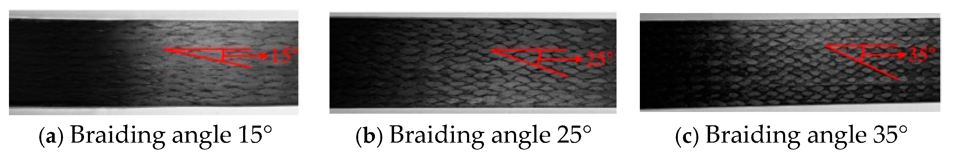
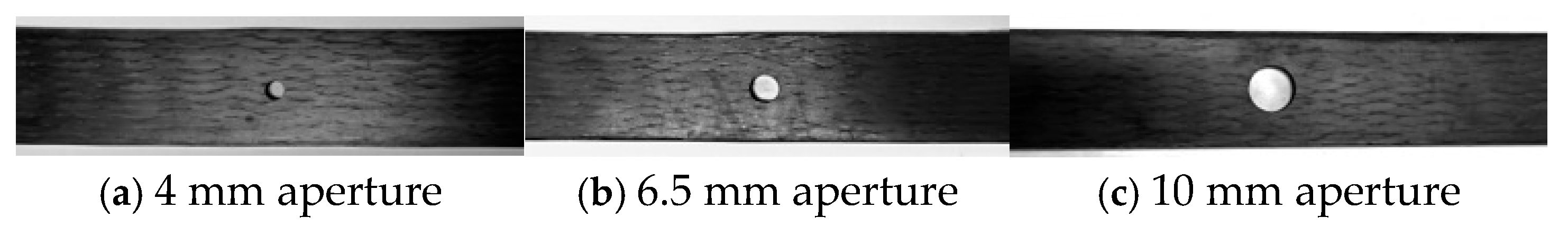
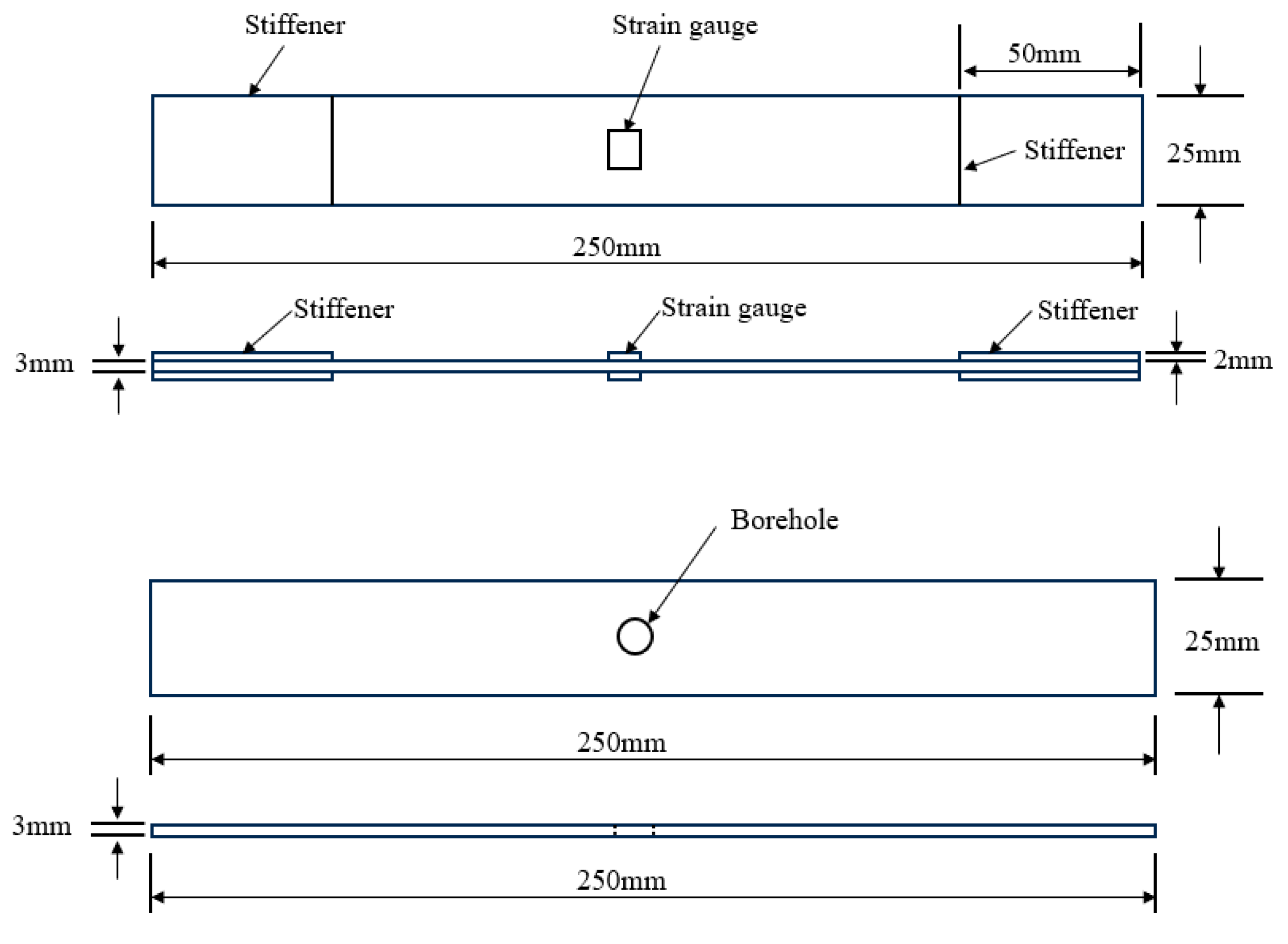
2.2. Prefabricated Part Design

The prefabrication of the 3D braided composites was carried out on a four-step (1 × 1) 3D programming machine. Figure 1 illustrates the fabrication process of the 3D braided composites. The braiding process involved setting braiding angles of 15°, 25°, and 35°, with section sizes of 3 × 25, 2 × 22, 2 × 21, and 2 × 20, and flower section lengths of 13.8, 8.05, and 5.5, respectively. The braided and axial yarns were mounted on the machine in accordance with the requirements for 3D five-way braiding. Based on the designed knitting angles and the flower joint length, the prefabricated components were tightened after each machine cycle, resulting in the prefabricated parts with varying knitting angles. After loading the prefabricated components into the mold, the mold was closed. Resin was then introduced into the mold using the vacuum-assisted resin transfer molding (VARTM) process, and the mold was subsequently heated and cured in the oven according to the prescribed curing cycle.
Bisphenol A epoxy resin JL-235 and curing agent JH-238 supplied by Changshu Jiafa Chemical Co., Ltd., China, were used in this study. The properties of the epoxy resin and curing agent are provided in Table 2. The epoxy resin and curing agent were mixed in a 50:17 ratio, and the entrapped air in the resin was removed by applying a vacuum in the empty chamber. The injection molding rate and pressure were then set. The resin was injected into the mold to fully infiltrate the prefabricated components. Subsequently, the resin flow pipeline was severed, the injection port of the mold was sealed, and the resin was cured at 50 °C for 3 h, followed by 70 °C for 7 h. After curing, the mold was cooled to room temperature, and the 3D braided composite test specimens were released.
In this study, three types of 3D braided composites with braiding angles of 15°, 25°, and 35° were fabricated using three distinct braiding parameters. The angle between the woven yarn and the longitudinal axis is referred to as the “knitting angle”. As the braiding angle increases, the applied force also increases. When the shearing force becomes excessive, the friction between the fiber and the shearing mechanism intensifies, leading to more severe yarn damage. This results in a deterioration of the composite’s mechanical properties and an increase in the uncertainty of the test results. Therefore, the maximum braiding angle of the 3D braided composite test specimens in this study was 35°. Three braiding angles (15°, 25°, and 35°), equally spaced, were chosen to investigate the effect of braiding angle on the mechanical properties of 3D braided composites. The test specimens with these braiding angles are shown in Figure 2.
Concurrently, three different bore sizes were designed and fabricated, with diameters of 4 mm, 6.5 mm, and 10 mm, respectively. The test specimen is shown in Figure 3.

2.3. Prefabricated Fiber Volume Fraction

The fiber volume fraction (Vf) of the prefabricated components was determined using the weighing method. The dry weight (Mf) of the 3D braided composite was measured prior to curing, and the total mass (Mc) was measured after curing. The matrix mass was calculated as Mm = McMf. The densities of carbon fiber and the matrix are known to be 1.8 g/cm3 and 1.13 g/cm3, respectively. Considering the impact of the voidage on the fiber volume fraction, the density of the test specimen (ρc) was measured using the density method. The porosity volume ratio was then calculated using Formula (1), followed by the calculation of the fiber volume fraction for each sample using Formula (2). The resulting fiber volume fractions are presented in Table 3.
V v = 1 M f / ρ f + ( M c M f ) / ρ m M c / ρ c
V f = M f / ρ f M f / ρ f + M m / ρ m + V v

2.4. Test Setup

In accordance with GB/T1449-2005, the 3D braided composite samples were sectioned into test specimens. A round hole was drilled at the center of mass of each specimen to create the required test configuration. The hole diameters were 4 mm, 6.5 mm, and 10 mm, respectively.
Standard test specimens were prepared in accordance with ASTM D3039 and ASTM D5766, and tensile tests were conducted on both non-porous and perforated specimens to determine their tensile strength and modulus. The dimensions and geometry of the test specimens are shown in Figure 4. For the tensile tests on test specimens without open holes, the clamping friction force was increased to mitigate early damage caused by stress concentration at both ends of the specimen. This increase in friction helped prevent slippage during the test. The clamping surfaces at both ends of the specimen were polished, and reinforcing plates made of 6061-T6 aluminum alloy were affixed to the ends of the specimen. Due to the intentional introduction of damage and stress concentration, no reinforcing plates were attached to the specimens with open holes.
The quasi-static tensile tests of the 3D braided composites, both with and without open holes, were conducted in accordance with ASTM D3039 and ASTM D5766. The tests were performed using an UTM5105 (Jinan Zhongte Testing Machine Co., Ltd., China) testing system, as shown in Figure 5. All tests were carried out at room temperature, with a constant loading rate of 2 mm/min, continued until specimen failure. For each set of data, 5–6 valid measurements were recorded, and the average value was calculated.
Following the tensile test, the fracture surface of the specimen was imaged using an optical microscope to analyze the damage modes of the 3D braided composites with varying braiding angles and aperture sizes.

3. Experimental Results and Discussion

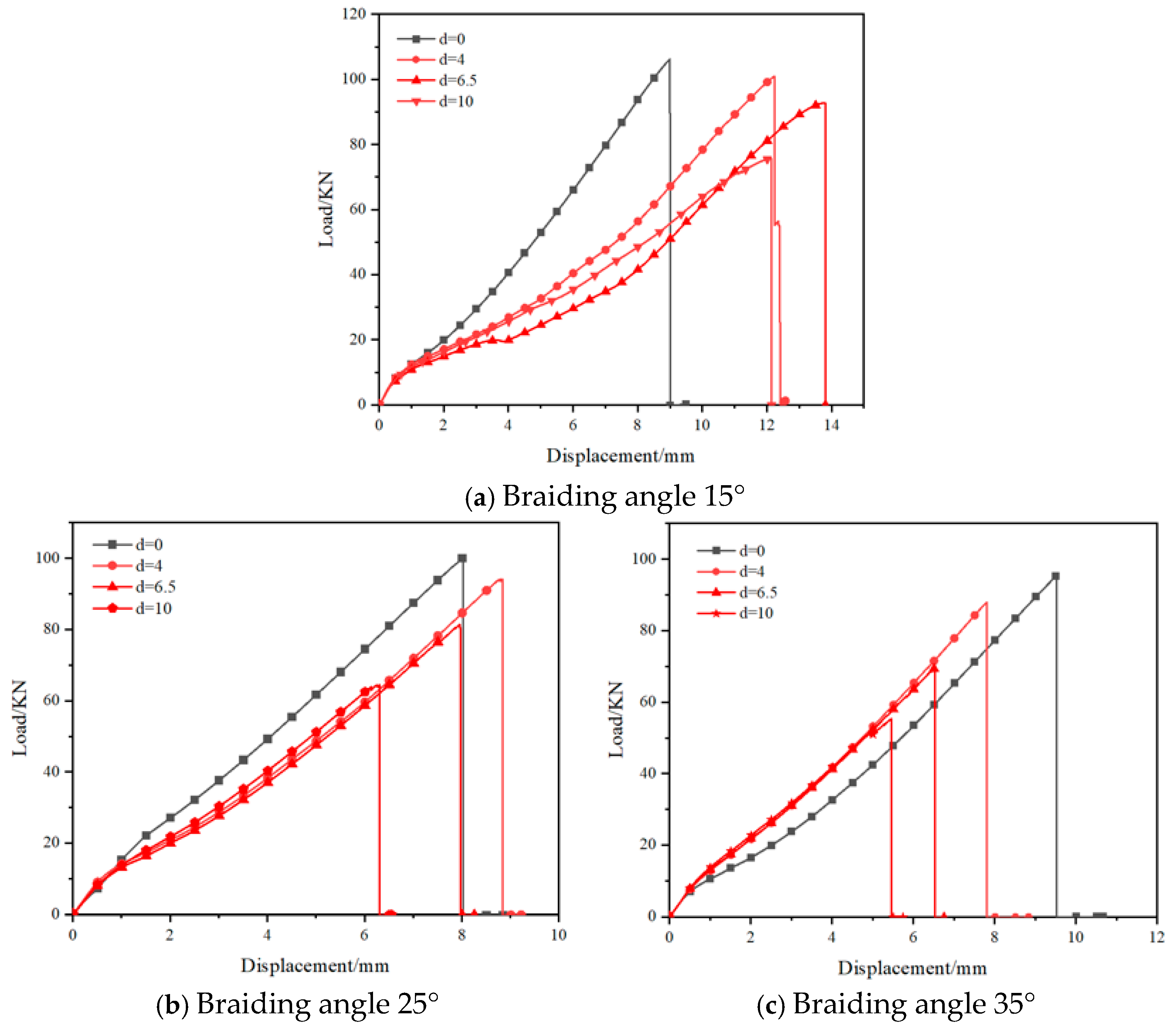
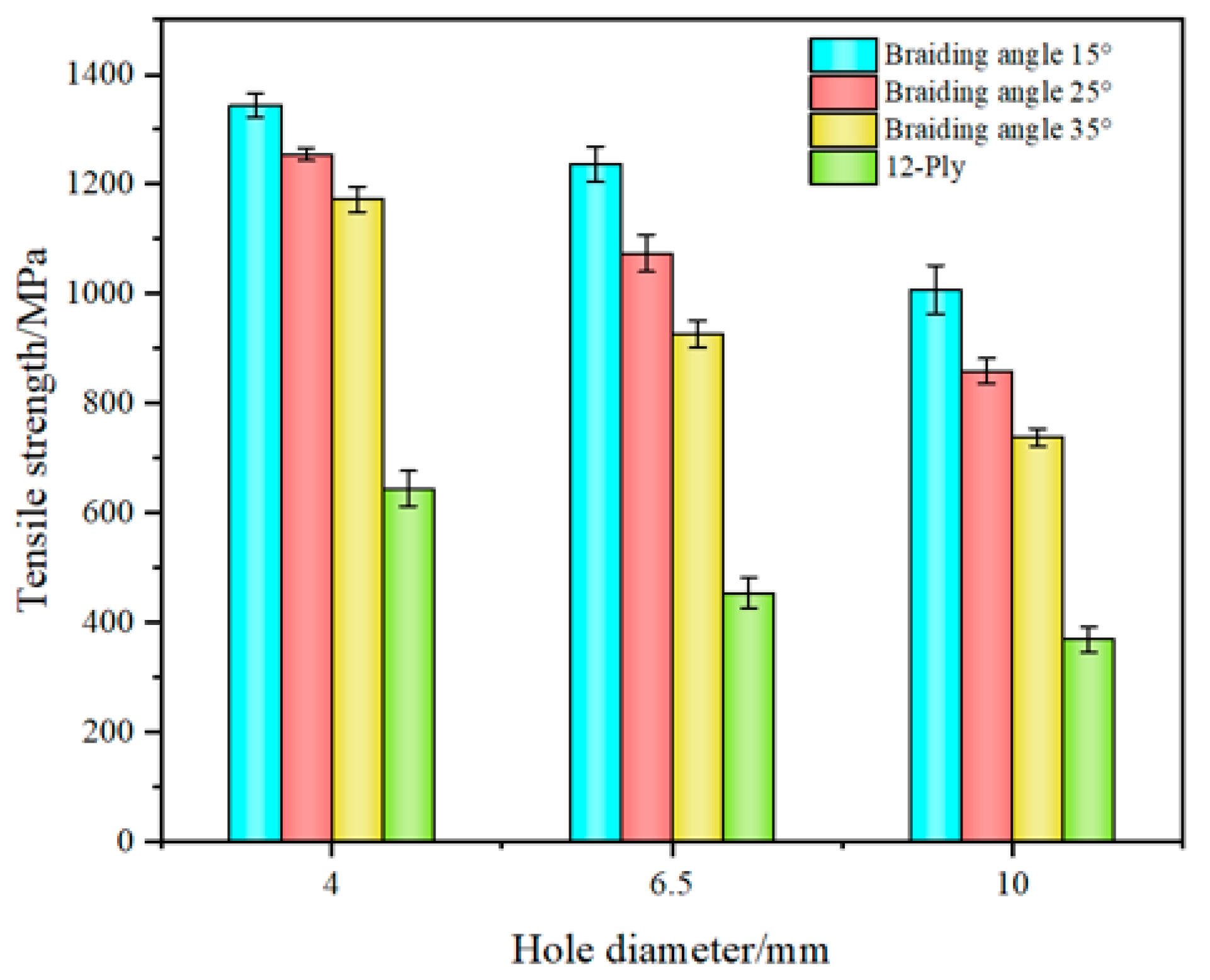
3.1. Effects of Different Braiding Angles and Apertures on the Mechanical Properties

In the calculation of the tensile strength, the cross-sectional area of the test specimens, both with and without open holes, was considered to be the same, with the total area of the specimen being w × t . The tensile strength of the specimens is given by Formula (3).
σ = P w × t
where σ is the strength of the test part, MPa; P is the failure load, N; w is the sample width (without considering the influence of the hole), mm; t is the sample thickness, mm.
Figure 6 presents the tensile load–displacement curves of the 3D braided composites with varying braiding angles and aperture sizes. As shown in Figure 6, the peak load of the open-hole specimens decreased with an increase in the aperture size, suggesting that the aperture size has a significant detrimental effect on the static tensile properties of the 3D braided composite. The load increased progressively with time during stretching. Once the peak load was reached, the load–displacement curve exhibited a sudden drop, resembling a “clipping” pattern. As the stress approached the tensile limit, the interwoven yarns fractured sequentially. As the crack propagated toward the yarn, the significant load-bearing capacity of the braided yarn delayed further the crack propagation. However, once the yarn’s load-bearing capacity was surpassed, the yarn fractured, and the stress reached the tensile strength limit, leading to specimen failure.
The 3D braided composites exhibited varying load-bearing capacities under the tensile stress. Figure 7 illustrates the tensile modulus of the 3D braided composite specimens with different braiding angles and aperture sizes. As shown in Figure 7, the tensile modulus decreased with the introduction of an open hole, and the sensitivity of the tensile modulus to the aperture increased significantly as the hole size enlarged. The tensile modulus of the 3D braided composites decreased as the braiding angle increased. This is because, with a higher braiding angle, the inclination angle of the braiding yarn also increased, which led to an increase in the axial angle of the yarn. In turn, it reduced the axial mechanical properties of the carbon fiber and increased the deformation of the 3D braided composite under the tensile loading. Compared with the decrease in tensile modulus observed at the three braiding angles, the rate of decrease became more pronounced as the braiding angle exceeded 25°. This behavior can be attributed to the change in the failure mode of 3D braided composites. As the braiding angle increased, interface debonding became the predominant failure mode, causing the specimen to fail more rapidly under the tensile loading. Consequently, the tensile modulus was significantly influenced at higher braiding angles.
Figure 8 illustrates the tensile strength of the 3D braided composites with varying apertures and braiding angles. The tensile strength exhibited a clear decrease as the pore diameter increased. However, the strength reduction in test specimens with different braiding angles showed varying sensitivities to drilling. Specifically, the strength reduction of the specimens with a 4 mm diameter at 15°, 25°, and 35° braiding angles was 5%, 5.89%, and 7.76%, respectively. At 15°, 25°, and 35°, the strength reduction of the specimens with a 6.5 mm diameter was 12.64%, 19.42%, and 27.11%, respectively. The same trend was observed for the 10 mm aperture specimens. As the braiding angle increased, the strength of the specimens became more sensitive to drilling. This was primarily due to the fact that as the braiding angle increased, the mechanical properties of the carbon fiber along the axial direction of the composite material degraded, leading to a shift in the failure mode from fiber fracture to interface debonding. The reduction in tensile strength exhibited distinct trends as the hole diameter varied. For the same braiding angle, the rate of tensile strength reduction increased with the aperture size. When the aperture was 4 mm, the tensile strength of the specimen with a 15° open hole decreased by only 5%, whereas the tensile strength of the specimens with 25° and 35° braiding angles decreased by 5.89% and 7.76%, respectively. In comparison to the 4 mm diameter, the tensile strength of the specimens with braiding angles of 15°, 25°, and 35° decreased by 8.03%, 14.38%, and 20.98%, respectively. When compared with the 10 mm diameter, the tensile strength of the specimens with braiding angles of 15°, 25°, and 35° decreased by 18.48%, 20.02%, and 20.32%, respectively. This phenomenon can be attributed to the stress concentration around the edge of the hole induced by the drilling process. As the aperture increases, the opening volume grows exponentially. For smaller apertures, the interwoven structure of the braided yarns remained relatively intact, and the movement between individual yarns was still constrained. As the aperture increased, the cross-structure of the braided preforms was significantly compromised during the drilling process, resulting in an inability to withstand the stress concentration around the opening under high tensile loading. It can be concluded that the tensile strength decreases significantly with an increase in pore size. For test pieces with varying braiding angles, smaller aperture openings were more effective in resisting higher stress concentrations around the hole, and as a result, the tensile strength remained largely unaffected by the presence of the opening.

3.2. Comparison of Tensile Test Data of Plain Woven Composites

It is evident that the material’s strength diminishes following the introduction of an opening. Significant technological differences exist between plain woven composites and 3D braided composites in terms of their fabrication processes, leading to distinct mechanical properties for each structure. A comparison was made between the drilled 3D braided composites and plain woven composites. As illustrated in Table 4, the tensile strength of the plain woven composite decreased significantly after drilling, in contrast to the relatively smaller reduction observed in the 3D braided composite. When the aperture of the plain woven composite was 4 mm, its tensile strength was 1055.5 MPa, which was 38.94% lower than the tensile strength observed at aperture sizes of 6.5 mm and 10 mm. The tensile strength decreased by 56.97% and 64.93% for the plain woven composites at aperture sizes of 6.5 mm and 10 mm, respectively. In contrast, the tensile strength of the 35° braided 3D composites with the same aperture sizes decreased by only 7.76%, 27.11%, and 41.93%, respectively. As shown in Figure 9, the plain woven composite could only maintain 35.07% to 61.05% of its original strength after the introduction of the opening, while the 3D braided composite retained 58.07% or more of its strength when subjected to the same apertures. When the aperture was 4 mm, the 3D braided composite with a higher braiding angles of 35° could maintain 92.24% of its original strength, while the plain woven composite with a braiding angles of 4° could only maintain 61.05%. As the aperture increased to 10 mm, the 3D braided composite with a 35° braiding angles could still retain 58.07% of its original strength, whereas the 3D braided composite with a 15° braiding angles maintained 71.21%. In comparison, the plain woven composite experienced significant strength loss, maintaining only 35.07% of its original strength at a 10 mm aperture.
The final strength of the 3D braided composite was higher than that of the plain braided composite in both the open-hole and non-porous conditions, primarily due to the superior structural integrity of the 3D braided composite. Thus, 3D braided composites exhibit higher impact damage tolerance and fracture toughness, effectively preventing delamination and enhancing both the overall mechanical properties and resistance to impact damage. Although plain woven composites are known for their high strength and fatigue resistance, they are made up of multiple layers of carbon fiber prepreg stacked together and bonded with adhesives or resins. This construction makes them more susceptible to delamination, which undermines their overall mechanical properties and impact damage resistance. As a result, the mechanical performance and impact resistance of plain woven composites are not as robust as those of 3D braided composites.

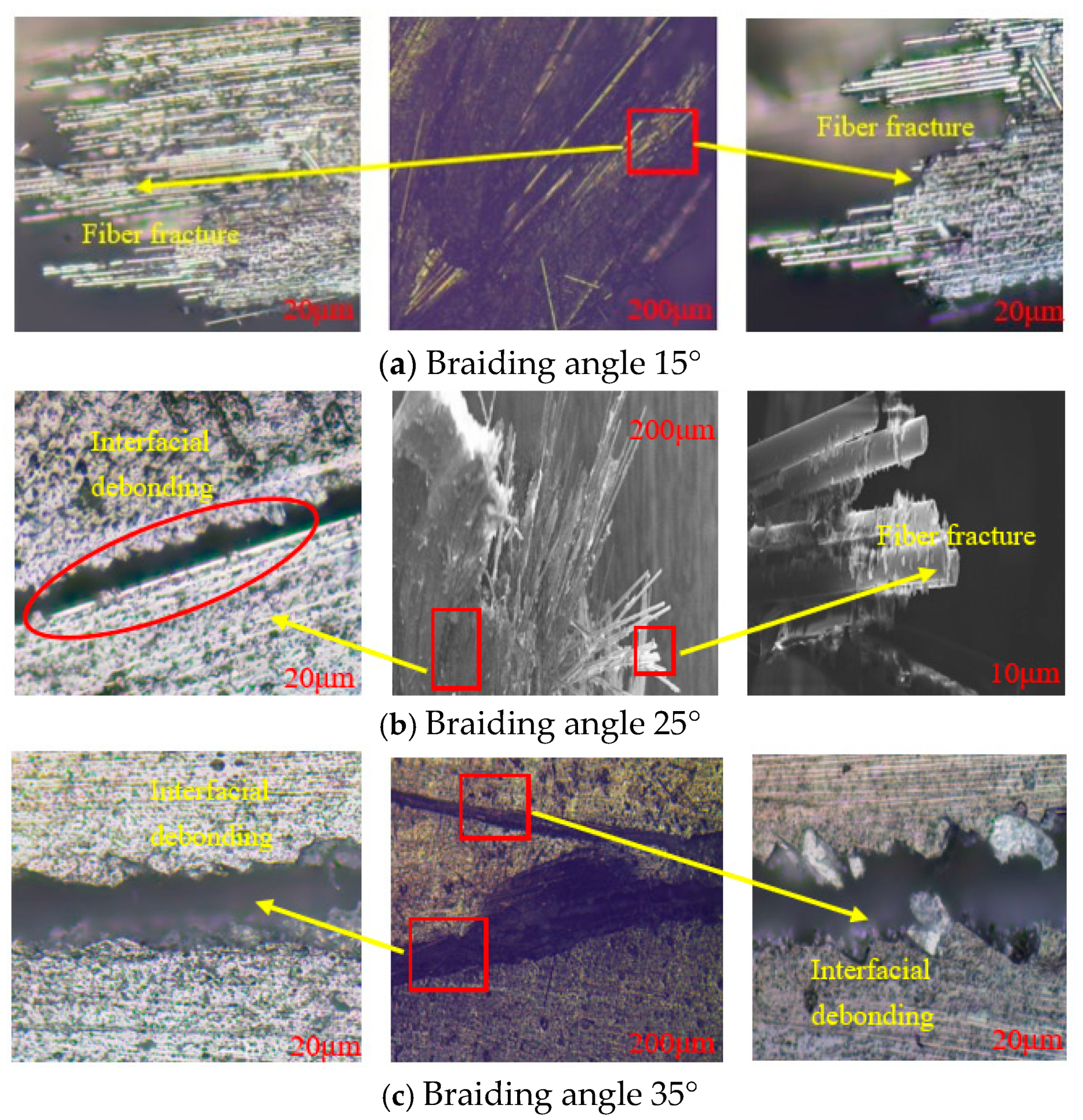
3.3. Tensile Failure Mechanism

3.3.1. Tensile Failure Mechanism of Non-Porous Test Parts

In the tensile test of the three types of 3D braided composites without open holes, there were no noticeable axial deformations or sounds during the test. However, when the specimen cracked, a loud sound was immediately produced, indicating a clear brittle material failure. This failure was primarily attributed to resin cracking and fiber fracture. Figure 10 shows the damage patterns of the test pieces at different angles. For the specimen with a braiding angle of 15°, a clear fiber fracture damage mode was observed at the fracture, with no apparent interface debonding, as shown in Figure 10a. The fracture direction of the yarn showed a tendency to break along the deflection direction of the braiding angle. Under the tensile loading, a large number of fibers fractured in clusters, leading to complete fracture. The matrix was severely damaged and could no longer effectively support the fibers. The main reason for this phenomenon is that the braided yarn has a small deflection angle relative to the longitudinal tensile axis. During the tensile test, the tensile load first causes the initial damaged yarn to break. The crack then continues to propagate transversely along the direction of the broken yarn, ultimately leading to the failure of the specimen. For the test piece with a braiding angle of 35°, the deflection angle between the braided yarn and the longitudinal axis was larger. As the braiding angle increased, the primary damage mode of the test piece shifted from fiber fracture to interface debonding. The observed failure area, as shown in Figure 10c, was significantly different from that of the 15° test piece. There were no broken fibers on the failure surface, and the entire failure area exhibited a fluffy failure pattern. The main reason for this phenomenon is that as the braiding angle increased, the braided structure became more tightly packed. When the crack reached the braided yarn area, the poor mechanical interface adhesion prevented the tensile load from being directly transmitted to the braided yarn. Instead, the load was conducted along the yarn direction, leading to the accumulation of cracks in the resin. These cracks eventually merged into larger cracks, resulting in the appearance of interface debonding as the final damage mode. For the test piece with a braiding angle of 25°, two damage modes—fiber fracture and interface debonding—occurred simultaneously. As shown in Figure 10b, it was observed that under the tensile load, the broken yarns primarily exhibited a shear fracture pattern. The adjacent braided yarns transferred the tensile load along their direction, which led to the interface debonding damage.
From the enlarged details of the damage, it was observed that a large number of fiber fractures occurred in the test piece with a 15° braid angle, as shown in Figure 11a, resulting in cluster fractures. The surfaces of the broken fibers remained relatively smooth, and no fragmented matrix material was observed. Figure 11b shows that, in addition to fiber fracture damage in the test piece with a 25° braiding angles, the poor adhesion between the fiber interfaces of different fiber bundles led to interface debonding. Figure 11c shows that the large braiding angle of the 35° test piece weakened the interface adhesion between the fiber and the matrix, leading to significant interface debonding damage within the test piece. During the stripping process, the resin matrix deformed, causing failure and adhesion to the surface of the fiber bundles. The images demonstrate that the three types of 3D braided composites without open holes exhibited distinct damage patterns at different braiding angles.

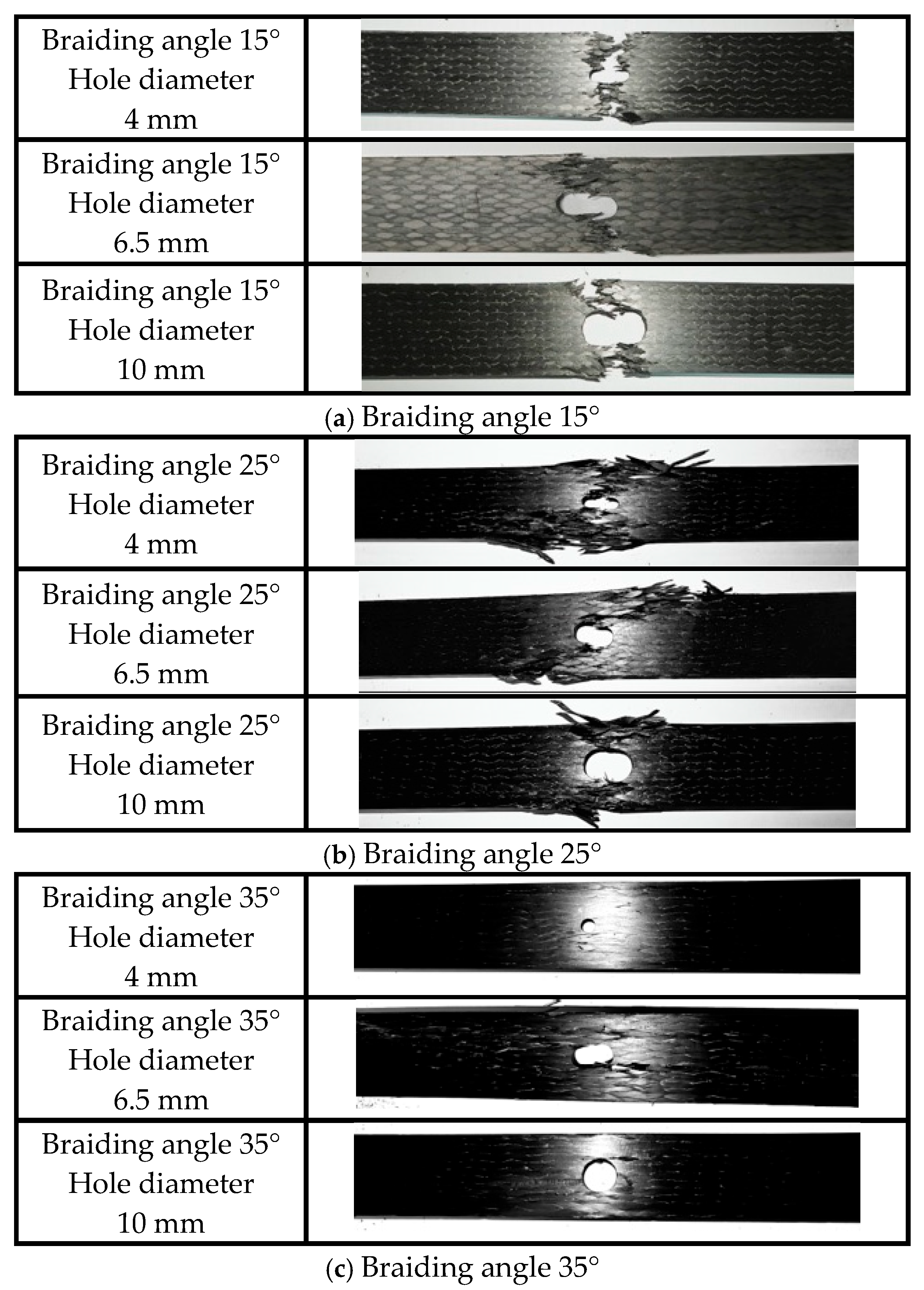
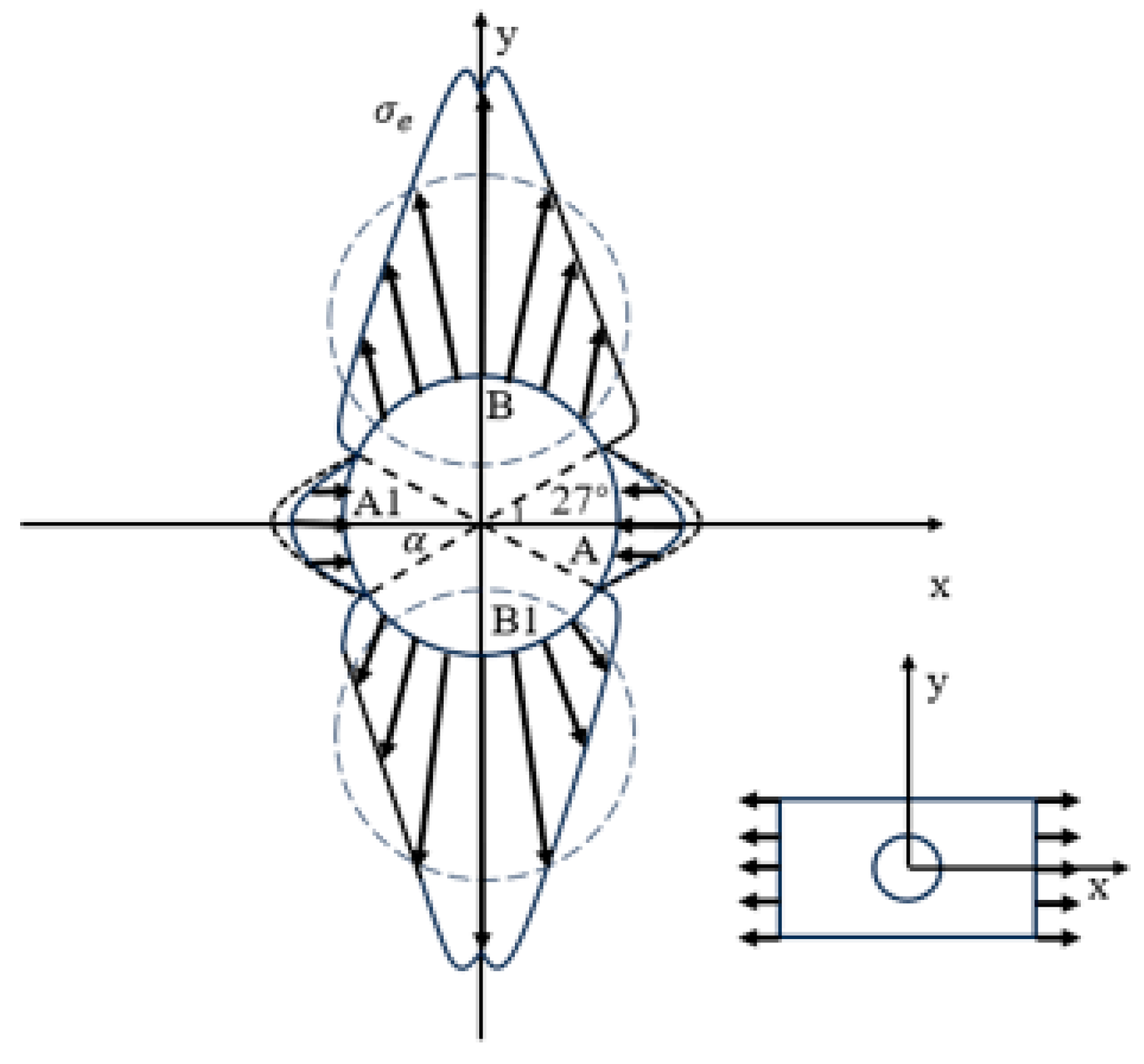
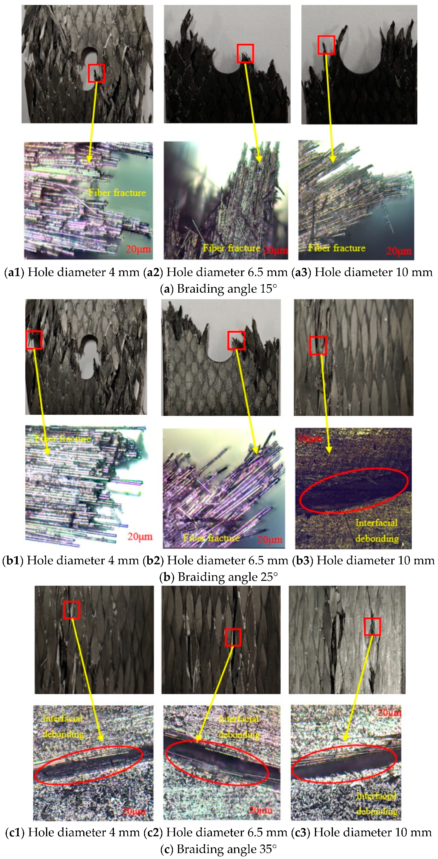
3.3.2. Tensile Failure Mechanism of Open Hole Test Parts

The damage patterns of the three types of three-dimensional braided composite test pieces with different braiding angles and apertures are shown in Figure 12. By comparing the fracture states of the test pieces under static tension, it was observed that the static failure initiated from the edge of the open hole. Under the tensile loading, the stress concentration point around the hole occurred at the junction of the hole boundary and the load direction. This resulted in the crack initiation at the stress concentration point, which then propagated along the stress concentration area, ultimately leading to the failure of the test piece. Due to the low braiding angle of the 15° test piece under the tensile loading, stress was initially concentrated around the hole. The fibers near the hole directly bore the tensile load, and they fractured once the ultimate tensile strength of the fiber was reached. Subsequently, the crack propagated laterally, and the test piece ultimately failed, exhibiting clear fracture openings and cracks at the failure site, as shown in Figure 12a. The failure mode was primarily fiber fracture. For the 25° test piece under the tensile loading, the crack first propagated longitudinally along the braid angle at the opening, then extended transversely, eventually leading to the failure of the test piece. The crack at the failure site followed the direction of the braid angle, with fiber fracture observed at the crack site, as shown in Figure 12b. The primary failure modes included fiber fracture and interface debonding. Due to the large braiding angle of the 35° test piece under tensile loading, the crack propagated between the fiber bundles due to poor fiber interface adhesion, which inhibited the transverse spread of the crack. As a result, the cracks primarily propagated longitudinally along the braid angle direction, and the failure patterns were predominantly fluffy. At the failure site, there were only a few matrix fragments and some shallow small cracks, with the entire interface remaining well-bonded and no fiber fracture occurring, as shown in Figure 12c. The damage to the composite test piece was minimal, and the primary failure mode was interface debonding. By comparing the damage extent of the test pieces with the same braiding angle but different aperture diameters, it can be seen that with a small number of fiber bundles, the test pieces with braiding angles of 15° and 25° could still maintain structural integrity at apertures of 4 mm and 6.5 mm. However, when the aperture reached 10 mm, the test pieces exhibited fractures and separation. Due to the change in damage mode in the 35° test piece, only a few cracks appeared at apertures of 4 mm and 6.5 mm. When the aperture reached 10 mm, large and distinct cracks developed along the direction of the braiding angle. Unlike the 15° and 25° test pieces, the 35° test pieces remained structurally connected after failure.
Three-dimensional braided composites have a periodic single-cell structure and can be regarded as orthotropic materials. As shown in Figure 13, according to the Lekhnitskii theory, under the action of unidirectional load (along the direction of the maximum elastic modulus), the maximum stress around the hole appears at the junction of the Y-axis and the hole (point B), and the stress concentration coefficient is K π 2 = 5.45 . The minimum stress occurs at the junction between the X-axis and the hole.
Failure modes of three 3D braided composite specimens with openings at different angles are shown in Figure 12. Under tensile load, the failure of the three types of specimens was mainly due to the propagation of cracks along the periphery of the hole and the braid angle, eventually leading to the failure of the test piece, which is consistent with the prediction of Figure 13 and Lekhnitskii theory. Under tensile load, the stress concentration point around the hole is the junction of the hole boundary and the load direction, so cracks and defects will inevitably start from the stress concentration point and spread along the stress concentration area, resulting in the failure of the structural part.
Figure 14 shows the damage magnification diagram of the test parts with different boreholes. Due to the low braid angle of the 15° test piece, it can be seen from the damage magnification detail diagram that the main damage mode was fiber fracture. With the increase in the hole diameter, the fiber was broken in clusters with a small hole diameter to disorderly fracture with a large hole diameter. The main reason for this phenomenon is that the effective area of the pore decreases with the increase in the pore diameter. Under the action of tensile load, the stress at the edge of the pore becomes more concentrated, and the fiber fracture becomes more disordered at the moment of failure. However, with the increase in aperture, the main failure mode does not change. Two failure modes occurred in the 25° test piece at all three pore diameters. The fiber fracture was more obvious at smaller pore diameters. With the increase in the pore diameter, more of the disadhesion phenomenon began to appear on the interface. In the 35° test, the interface desticking damage mode was displayed under three kinds of aperture, and the main damage mode did not change significantly with the increase in aperture. It can be concluded that the aperture factor has no obvious effect on the damage mode.

4. Conclusions

In this study, three test specimens featuring distinct braiding angles were fabricated employing a four-step technique on a 3D braiding machine, with three varying hole diameters strategically introduced. The static tensile properties, fracture characteristics, and damage failure modes of these specimens were comprehensively analyzed. Furthermore, the influence of varying braiding angles and hole diameters on the damage failure mechanisms of 3D braided composites under static tensile loading was explored in depth.
(1)
The tensile modulus of 3D braided composites exhibited a reduction upon the introduction of perforations. As the size of the opening increased, the tensile modulus decreased accordingly. The tensile modulus decreased with increasing knitting angle, and the rate of reduction accelerated once the knitting angle exceeded 25°. At elevated braiding angles, the tensile modulus was significantly influenced.
(2)
The three types of 3D braided composite specimens could sustain a strength value of 58.07% or higher, even after the introduction of apertures, demonstrating superior damage tolerance compared with laminate composites. The plain braided composite retained a strength value ranging from 35.07% to 61.05% after aperture introduction, with the test specimen nearing failure at larger apertures. It can be concluded that the 3D braided composite exhibited insensitivity to the presence of apertures.
(3)
When the braiding angle increased from 15° to 25°, the failure mode of the 3D woven composite changed from fiber fracture failure to the simultaneous occurrence of fiber fracture and interfacial debonding. When the braiding angle further increased to 35°, its failure mode transformed into interfacial debonding.
(4)
Under the current parameters, after introducing the opening, static failure started from the edge of the opening, and the failure mode was that cracks propagated along the edge of the hole, ultimately leading to the failure of the test piece. Unlike the 15° and 25° test specimens, the 35° test specimen remained connected after failure. The increase in aperture had no significant effect on the failure mode.
In future work, our aim is to build a numerical simulation model to compare with the experimental results. This will enable us to further explore the effects of weaving angle and aperture on the mechanical behavior of composites and verify our experimental results. However, at this stage, direct theoretical predictions of the mechanical properties of 3D five-way braided composites remain challenging due to the complex fiber structures and manufacturing defects that are not fully captured by classical theoretical models such as lamination theory or the Tsai–Hill criterion. In the future, we will establish an accurate numerical simulation framework for these composite materials that includes the Tsai–Hill criterion and will further improve and verify the effects of weaving angle and aperture on the tensile properties and failure mechanisms.

Author Contributions

H.S.: Conceptualization, Project administration, Funding acquisition. Z.H.: Visualization, Investigation, Writing—original draft. T.W.: Software, Validation, Writing—review and editing. D.A.: Software, Validation. Q.Q.: Formal analysis, Supervision. Z.W.: Methodology, Data curation. All authors have read and agreed to the published version of the manuscript.

Funding

This research was supported by the Guangxi University of Science and Technology Doctoral Fund Project (grant number 20Z40) and the Guangxi Science and Technology Plan and Project (grant numbers AD21220145 and AD23026317).

Institutional Review Board Statement

Not applicable.

Informed Consent Statement

Not applicable.

Data Availability Statement

The data presented in this study are available on request from the corresponding author.

Conflicts of Interest

The authors declare no conflict of interest.

References

  1. Warren, K.C.; Lopez-Anido, R.A.; Vel, S.S.; Bayraktar, H.H. Progressive failure analysis of three-dimensional woven carbon composites in single-bolt, double-shear bearing. Compos. Part B 2016, 84, 266–276. [Google Scholar] [CrossRef]
  2. Isart, N.; El Said, B.; Ivanov, D.S.; Hallett, S.R.; Mayugo, J.A.; Blanco, N. Internal geometric modelling of 3D woven composites: A comparison between different approaches. Compos. Struct. 2015, 132, 1219–1230. [Google Scholar] [CrossRef]
  3. Anitha Priyadharshani, S.; Meher Prasad, A.; Sundaravadivelu, R. Analysis of GFRP stiffened composite plates with rectangular cutout. Compos. Struct. 2017, 169, 42–51. [Google Scholar] [CrossRef]
  4. Hwan, C.-L.; Tsai, K.H.; Chiu, C.H.; Huang, Y. Strength prediction of woven hybrid composite laminates each with a center hole. J. Compos. Mater. 2014, 48, 1637–1644. [Google Scholar] [CrossRef]
  5. Toubal, L.; Karama, M.; Lorrain, B. Stress concentration in a circular hole in composite plate. Compos. Struct. 2005, 68, 31–36. [Google Scholar] [CrossRef]
  6. Mohammadi, R.; Najafabadi, M.A.; Saeedifar, M.; Yousefi, J.; Minak, G. Correlation of acoustic emission with finite element predicted damages in open-hole tensile laminated composites. Compos. Part B 2017, 108, 427–435. [Google Scholar] [CrossRef]
  7. Wang, Z.-Y.; Wang, Q.-Y.; Li, L.; Zhang, N. Fatigue behaviour of CFRP strengthened open-hole steel plates. Thin Walled Struct. 2017, 115, 176–187. [Google Scholar] [CrossRef]
  8. Saleh, M.N.; Wang, Y.; Yudhanto, A.; Joesbury, A.; Potluri, P.; Lubineau, G.; Soutis, C. Investigating the Potential of Using Off-Axis 3D Woven Composites in Composite Joints’ Applications. Appl. Compos. Mater. 2017, 24, 377–396. [Google Scholar] [CrossRef]
  9. Xu, F.; Sun, L.; Zhu, L.; Yang, S.; Hui, D.; Qiu, Y. X-ray 3D microscopy analysis of fracture mechanisms for 3D orthogonal woven E-glass/epoxy composites with drilled and moulded-in holes. Compos. Part B 2018, 133, 193–202. [Google Scholar] [CrossRef]
  10. Song, J.; Wen, W.; Cui, H.; Wang, Y.; Lu, Y.; Long, W.; Li, L. Warp direction fatigue behavior and damage mechanisms of centrally notched 2.5D woven composites at room and elevated temperatures. Compos. Sci. Technol. 2019, 182, 107769. [Google Scholar] [CrossRef]
  11. Sun, G.; Wang, L.; Chen, D.; Luo, Q. Tensile performance of basalt fiber composites with open circular holes and straight notches. Int. J. Mech. Sci. 2020, 176, 105517. [Google Scholar] [CrossRef]
  12. Gao, X.; Wen, D.; Siddique, A.; Liu, T.; Fan, W.; Chen, H.; Yu, J.; Cao, M. Flexural performance of three-dimensional braided open-hole composite with different hole diameter and preform size. J. Ind. Text. 2022, 52, 15280837221121939. [Google Scholar] [CrossRef]
  13. Dong, J.; Gong, Y. Influence of void defects on progressive tensile damage of three-dimensional braided composites. J. Compos. Mater. 2018, 52, 2033–2045. [Google Scholar] [CrossRef]
  14. Wu, C.; Lai, W.-Y. Mechanical and open hole tensile properties of self-reinforced PET composites with recycled PET fiber reinforcement. J. Appl. Polym. Sci. 2016, 133, 43682. [Google Scholar] [CrossRef]
  15. Bian, T.; Guan, Z.; Liu, F. Compressive experiment and numerical simulation of 3D carbon/carbon composite open-hole plates. Arch. Appl. Mech. 2018, 88, 913–932. [Google Scholar] [CrossRef]
  16. Li, X.; Wang, L.; Zhao, W.; Wu, H.; Xu, B. Selection and analysis of optimum stacking sequence and geometry dimensions on bismaleimides composite joints under tensile loading. Polym. Test. 2022, 105, 107421. [Google Scholar] [CrossRef]
  17. Green, B.G.; Wisnom, M.R.; Hallett, S.R. An experimental investigation into the tensile strength scaling of notched composites. Compos. Part A 2007, 38, 867–878. [Google Scholar] [CrossRef]
  18. Su, H.; Deng, K.; Yang, D.; Zhan, X.; Xie, Z.; Qin, J.; Ma, L. Performance and failure analysis of perforated CFRP/aluminum alloy bonding and self-piercing riveting hybrid joints. Eng. Fail. Anal. 2024, 156, 107803. [Google Scholar] [CrossRef]
  19. Gu, Q.; Quan, Z.; Shen, M.; Xie, Y.; Yu, J. Fabrication and braiding angle effect on the improved interlaminar shear performances of 3D braided sandwich hybrid composites. J. Mater. Res. Technol. 2023, 25, 5795–5806. [Google Scholar] [CrossRef]
  20. Wang, X.; Li, H.; Zhang, Y.; Guan, Y.; Yan, S.; Zhai, J. Compressive Failure Characteristics of 3D Four-Directional Braided Composites with Prefabricated Holes. Materials 2024, 17, 3821. [Google Scholar] [CrossRef]
  21. Singh, A.; Reynolds, N.; Keating, E.M.; Barnett, A.E.; Barbour, S.K.; Hughes, D.J. The effect of braid angle on the flexural performance of structural braided thermoplastic composite beams. Compos. Struct. 2021, 261, 113314. [Google Scholar] [CrossRef]
  22. Li, D.-S.; Han, W.-F.; Jiang, L.; Fang, D.-N. Fatigue behavior and failure of three-dimensional six-directional braided composites under tension. Mater. Lett. 2023, 332, 133471. [Google Scholar] [CrossRef]
  23. Liu, Z.; Wang, Y.-B.; Ou, J. Experiments and progressive damage analyses of three-dimensional full five-directional braided composites under three-point bending. Polym. Compos. 2015, 37, 2478–2493. [Google Scholar] [CrossRef]
  24. Cui, C.; Dong, J.; Mao, X. Effect of braiding angle on progressive failure and fracture mechanism of 3-D five-directional carbon/epoxy braided composites under impact compression. Compos. Struct. 2019, 229, 111412. [Google Scholar] [CrossRef]
  25. Dai, S.; Cunningham, P.R.; Marshall, S.; Silva, C. Influence of fibre architecture on the tensile, compressive and flexural behaviour of 3D woven composites. Compos. Part A 2015, 69, 195–207. [Google Scholar] [CrossRef]
  26. Yuan, H.; Wen, W.; Wang, Y.; Zheng, Z.; Wu, X. A model for longitudinal tensile strength prediction of low braiding angle three-dimensional and four-directional composites. Sci. Eng. Compos. Mater. 2017, 24, 447–453. [Google Scholar] [CrossRef]
  27. Li, Y.; Pan, Z.; Gu, B.-H.; Sun, B. Numerical analysis of punch shear failure and stress characteristics of three-dimensional braided composite with different braiding angles. Int. J. Damage Mech. 2019, 28, 1418–1437. [Google Scholar] [CrossRef]
  28. Zhang, D.; Zheng, X.; Zhou, J.; Song, X.; Jia, P.; Liu, H.; Liu, X. Effect of Braiding Architectures on the Mechanical and Failure Behavior of 3D Braided Composites: Experimental Investigation. Polymers 2022, 14, 1916. [Google Scholar] [CrossRef]
  29. Gao, X.; Siddique, A.; Sun, B.; Gu, B. Influence of Braiding Angle on Multiple Impact Damages of 3-D Braided Composite along Longitudinal Direction. Appl. Compos. Mater. 2019, 26, 1261–1280. [Google Scholar] [CrossRef]
  30. Jang, Y.; Kim, J.-H.; Lee, D.; Chon, J.S.; Lee, S.; Kwon, D.-J. Comprehensive analysis of the effect of braiding angle on the wettability and mechanical properties of 3D braided carbon fiber fabric-reinforced composites. Mater. Today Commun. 2024, 41, 110798. [Google Scholar] [CrossRef]
  31. Zhu, H.; Li, D.-S.; Han, W.-F.; Jiang, L. Experimental and numerical study of in-plane compressive properties and failure of 3D six-directional braided composites with large braiding angle. Mater. Des. 2020, 195, 108917. [Google Scholar] [CrossRef]
Figure 1. Fabrication process of the 3D braided composite.
Coatings 15 00440 g001
Figure 2. Test parts with different braiding angles.
Coatings 15 00440 g002
Figure 3. Test parts with different apertures.
Coatings 15 00440 g003
Figure 4. Size and geometry of the test piece.
Coatings 15 00440 g004
Figure 5. UTM5105 test system.
Coatings 15 00440 g005
Figure 6. Tensile load–displacement curves of the 3D braided composites with different braiding angles and apertures.
Coatings 15 00440 g006
Figure 7. Tensile modulus of the 3D braided composite test pieces with different braiding angles and different apertures.
Coatings 15 00440 g007
Figure 8. Tensile strength of the 3D braided composites at different apertures and braiding angles.
Coatings 15 00440 g008
Figure 9. Comparison of damage tolerance between the 3D braided composites and plain woven composites.
Coatings 15 00440 g009
Figure 10. Damage morphology of 3D braided composites without holes at different braiding angles.
Coatings 15 00440 g010
Figure 11. Optical microscope photos of the fracture surface of the non-porous test pieces at different braiding angles.
Coatings 15 00440 g011
Figure 12. Damage morphology of the open hole test pieces at different braiding angles.
Coatings 15 00440 g012
Figure 13. Stress distribution around the hole.
Coatings 15 00440 g013
Figure 14. Optical microscope photos of borehole fracture at different braiding angles.
Coatings 15 00440 g014
Table 1. Mechanical properties of the T700sc-12K carbon fiber.
PropertiesValues
Elastic modulus/GPaE11230
E2214
E3314
Shear modulus/GPaG129
G139
G235
Poisson’s ratio/[1]μ120.25
μ130.25
μ230.3
Table 2. Properties of the epoxy resin and curing agent.
NameChemical ComponentViscosity (mpa·s°C)Epoxy Equivalent (g/eq)Mixing Ratio
JL-235Epoxy resin2000–4000180–188100:34
JH-238Curing agent5–15-
Table 3. Fiber volume fraction.
Braiding AngleFiber Volume Fraction
15°55%
25°55%
35°55%
Table 4. Data of the tensile properties of the three-dimensional braided composites and plain woven composites.
MaterialNo Defect Strength (MPa)Hole Diameter 4 mm (MPa)Hole Diameter 6.5 mm (MPa)Hole Diameter 10 mm (MPa)
Braiding Angle 15°1415.3 ± 15.21344.4 ± 22.11236.4 ± 33.51007.9 ± 44.8
Braiding Angle 25°1333.1 ± 21.71254.5 ± 12.41074.1 ± 34.3859.1 ± 23.6
Braiding Angle 35°1271.0 ± 20.41172.4 ± 23.7926.4 ± 25.5738.1 ± 16.5
Plain Woven Composite1055.5 ± 17.1644.43 ± 32.2454.23 ± 28.1370.13 ± 10.4
Disclaimer/Publisher’s Note: The statements, opinions and data contained in all publications are solely those of the individual author(s) and contributor(s) and not of MDPI and/or the editor(s). MDPI and/or the editor(s) disclaim responsibility for any injury to people or property resulting from any ideas, methods, instructions or products referred to in the content.

