Article

Facile Synthesis of Sponge-like Microstructured CuO Anode Material for Rechargeable Lithium-Ion Batteries

1
National Center for Advanced Battery Research, National Institute of Fundamental Studies, Kandy 20000, Sri Lanka
2
Department of Applied Erath Sciences, Uva Wellassa University, Badulla 90000, Sri Lanka
3
Department of Physics and Electronics, University of Kelaniya, Kelaniya 11600, Sri Lanka
4
Center for Synchrotron Radiation Research, Japan Synchrotron Radiation Research Institute (JASRI), 1-1-1 Kouto, Sayo-cho, Sayo-gun, Hyogo 679-5198, Japan
*
Author to whom correspondence should be addressed.
Coatings 2025, 15(4), 467; https://doi.org/10.3390/coatings15040467
Submission received: 17 February 2025 / Revised: 2 April 2025 / Accepted: 12 April 2025 / Published: 15 April 2025

Abstract

:
CuO was synthesized by employing the facile chemical precipitation technique to vary the concentrations of Cu(NO3)2 in a range from 0.001 to 0.1 M. This was carried out in order to find the concentration of Cu(NO3)2 that results in optimal electrochemical performance in CuO as an anode electrode material for lithium-ion batteries. Among the investigated concentrations, the 0.03 M Cu(NO3)2 showed the best electrochemical performance. Of the synthesized materials, the scanning electron microscopic (SEM) analysis revealed the existence of a sponge-like morphology. X-ray photoelectron spectroscopy (XPS), X-ray diffraction (XRD), synchrotron X-ray diffraction (SXRD) and Raman spectrum confirmed the formation of a required CuO phase. The electron density distribution on the crystalline structure of the synthesized CuO indicates the existence of the highest distribution of electrons around Cu atoms, with enhanced productivity of the conversion mechanism during the cycling process. Further, this study shows that the electronic interfacial properties of Cu/CuO could be improved by optimizing the amount of acetylene black used for the electrode fabrication, with 20 wt% being the optimum value. The electrodes fabricated with the synthesized sponge-like microstructured CuO as the active material exhibited a high initial specific discharge capacity of 3371.9 mA h g−1 and resulted in a specific discharge capacity of 442.9 mA h g−1 (Coulombic efficiency of 97.4%) after 50 cycles, at a rate of 0.2 C. Moreover, the specific discharge capacity reported at the rate of 1.0 C was 217.6 mA h g−1 with a significantly high Coulombic efficiency of about 98.0% after 50 cycles. Altogether, this study reveals the high potentiality of using sponge-like microstructured CuO as a high-performance anode electrode material for LIBs.

1. Introduction

Lithium-ion batteries (LIBs) have gained considerable attention after the Sony Group Corporation introduced them for commercialized applications in 1991 [1,2]. At the moment, LIBs are broadly used in various industrial applications, especially in electric vehicles, portable electronic devices and grid storage [3]. Consequently, the requirement for LIBs will be intensely increased in the coming years with the present rapid advancements in related industrial applications, and hence, further developments in LIB technology are crucial [1]. Currently, graphite (artificial or mined graphite) is used as the main commercial anode electrode material for LIBs [4,5]. A low theoretical specific capacity of 372 mA h g−1, low discharge potential and the expensive and environmentally disadvantageous processes used to obtain battery-grade graphite are the main disadvantages of using graphite anode for LIBs [6,7]. The above-mentioned disadvantages of graphite anode limit its further development for LIBs.
Introduction of alternative anode electrode materials to LIBs is crucial for overcoming the above-mentioned disadvantages involved with graphite. Tarascon et al. have introduced transition metal oxides (TMOs) as anode materials for LIBs in 2000 [8]. In recent years, TMOs have received significant attention as anode materials because of their high theoretical specific capacities compared to conventional graphite electrode material [9]. Among the various types of potential TMOs, cupric oxide (CuO) has become an important semiconducting material due to its potential for the use in different types of applications, such as in solar cells [10], supercapacitors [11], gas sensors [12], catalysts [13] and LIBs [14]. Owing to its unique advantages of high theoretical capacity (674 mA h g−1), high safety, natural abundance, low cost, non-toxicity, environmental friendliness, high purity, ease of production, chemical stability and ease of storage, CuO is highly regarded as an attractive anode electrode material for LIBs [15,16].
The reason behind this successful use of CuO for the anode application of LIBs is that the Fermi level of CuO is located below the Fermi level of Li within the electrolyte stability window. Accordingly, CuO has been successfully tested and endorsed as a promising anode electrode material for LIBs, as reported elsewhere [7,8]. Specifically, Zhang et al. reported promising electrochemical performance of full cells of LIBs fabricated with CuO as the anode electrode materials and LiNi0.5Mn1.5O4 as the cathode electrode materials [17]. In 2017, Qian et al. reported a similar successful outcome studying the electrochemical performance of full cells of LIBs fabricated with CuO as the anode electrode material and commercial LiNi1/3Mn1/3Co1/3O2 as the cathode electrode materials [18]. Furthermore, recently in 2020, a very promising electrochemical performance for a LIB full cell with CuO as the anode material and LiMn2O4 cathode material was reported by Jose et al. [19].
By contrast, the CuO electrode has a potentiality to be used as cathode electrode material in some cases, such as for zinc ion and aluminum ion batteries, due to the Fermi level of Zn and Al being located below the Fermi level of the CuO electrode [20,21]. However, in the case of the lithium-ion battery, CuO has been widely investigated and successfully developed by a number of renowned research groups worldwide as a crucial anode electrode material for rechargeable batteries [7,8,9,14,15,16].
In the LIB applications, it has been reported that the electrochemical performance of the CuO anode electrode significantly depends on the morphological interfacial properties of CuO/electrolyte and the electronic interfacial properties of Cu/CuO [15,19]. Hence, morphological modification is another approachable technique for enhancing morphological interfacial properties of CuO/electrolyte. The modified morphological interfacial properties of CuO/electrolyte could suppress the volume expansion of the CuO electrode during the cycling process and increase the contact area between the CuO/electrolyte interface, thereby shortening the diffusion path for Li+ ions [22,23]. This allows for facilitating diffusion of Li+ ions, faster reaction rates, a more stable structure and hence, improved electrochemical performance for LIBs. Accordingly, previous studies have reported different types of morphological modification to CuO, such as developing three-dimensional clusters of peony-shaped CuO [24], thorn-like CuO [25], hierarchical CuO [26], nanochain CuO [16] and nanoslice CuO in order to enhance the morphological interfacial properties of CuO/electrolyte.
Already, a wide range of synthesis techniques, such as the SILAR technique [27], self-assembled synthesis [26], electrodeposition [28] and electrospinning [29], hydrothermal technique [19,30,31,32] have been investigated to obtain various morphologically modified CuO electrodes. However, these techniques involve some disadvantages, such as multiple complicated processes, difficulty in scaling up the process and the need for expensive chemicals such as cetyltrimethylammonium bromide (CTAB) [24], poly-ethylene glycol (PEG, Mw= 20,000) [16] and non-ionic surfactant [(C6H9NO) n—PVP]. In addressing these drawbacks, it is crucial to introduce a facile, low-cost and environmentally friendly synthesizing approach for CuO electrode materials.
The synthesis techniques used in the present study are based on a simple and convenient chemical precipitation technique, which has been proven to be a promising technique to obtain CuO particles with a promising morphology for the anode material in LIBs. More importantly, this study focused on synthesizing micro-scaled sponge-like CuO particles without using any expensive chemicals and avoiding multistep processes.
In addition, this paper presents an extended study performed to discuss the importance of the electronic interfacial properties of Cu/CuO. Such an account of information relating to improvement of the electrochemical performance of LIBs has not been published before. Altogether, this study reveals the capability of CuO with micro-scale sponge-like morphology for use in the anode electrode of LIBs.

2. Materials and Methods

2.1. Materials Preparation

Analytical-grade Cu(NO3)2·3H2O (obtained from VWR with purity > 99.0%) and NaOH (obtained from VWR with purity > 99.0%) were used as the starting materials. According to preliminary investigations of this research work, CuO was synthesized for different Cu(NO3)2·3H2O solution concentrations ranging from 0.001 M to 0.1 M. Under that, the concentrations of 0.001, 0.02 M, 0.03 M, 0.04 M, 0.05 M and 0.1 M were investigated in order to find the optimum solution concentration among them before proceeding to the next step of the detailed investigation of the electrochemical performance of developed CuO anode materials. There, it was found that the CuO electrode exhibited some noteworthy electrochemical performances for the concentrations of 0.02 M, 0.03 M, 0.04 M and 0.05 M, while the 0.03 M concentration showed the best performance. Each solution was kept at 50 °C with a vigorous stirring speed of 200 rpm for one hour.
For the material synthesis, 0.050 g of solid NaOH (platelets) was added to the solution and mixed gradually until a large amount of black precipitate was obtained. Then, the solution was heated at 50 °C for 30 min, and the product was washed with deionized water several times until the pH reached 7 to remove the residuals before characterization. Thereafter, the product was kept at 80 °C until dried and subjected to necessary material characterization.

2.2. Characterization of the Synthesized Materials

The particle morphology of the synthesized materials in the form of fine powder was analyzed by Scanning Electron Microscope (SEM) (EEVO/LS ZEISS) (Carl Zeiss AG, Oberkochen, Germany). X-ray Photoelectron Spectroscopy (XPS) was performed using Thermo ScientificTM ESCALAB Xi+ (Thermo Fisher Scientific, Waltham, MS, USA) with Mg Kα (h ν = 1253.6 eV). The phase analysis of the synthesized materials was performed by powder X-Ray Diffraction (XRD) using an X-ray diffractometer (Rigaku Ultima IV, Tokyo, Japan) with Cu Kα radiation (λ = 1.5406 Å) in the 2 θ range of 10° to 80° with a scanning rate of 1° s−1 and step size of 0.2. Furthermore, in order to examine the formation of CuxO phases during the synthesis process, the synthesized materials were characterized using Synchrotron X-Ray Diffraction (SXRD). The SXRD experiments were conducted using the BL19B2 beamline facility at the SPring-8 third-generation synchrotron radiation facility, Hyogo, Japan. For that, a Si (111) monochromator was used to direct incident X-rays with a wavelength of 0.413269 Å (X-ray energy ≈ 30 keV) during the measurements. The intensity of the incident X-ray beam was measured using an ionization chamber containing nitrogen gas with 99.99% purity. The powder samples were filled into the 0.3 mm Lindermann capillary tube, and the diffracted X-rays were collected by a two-dimensional PILATUS-300K detector (Pilatus Aircraft Ltd., Stans, Switzerland) with a camera length at approximately 270.23 mm from the sample. Laser Raman Spectroscopy (LRS) studies were performed at room temperature between 100 and 1000 cm−1 using a Renishaw Invia Raman spectrometer (Renishaw, Dundee, UK) with a 514 nm laser. The optical characterization of the prepared samples was taken using a UV−Vis-NIR spectrometer (Shimadzu UV-Vis. 2450, Shimadzu Corporation, Tokyo, Japan) within the wavelength range of 300–900 nm in reflectance mode with spectral-grade BaSO4 as reference material. The surface area of the synthesized materials were analyzed using the Brunauer–Emmett and Teller (BET) method using a Quantichrome Autoflow Bet+ analyzer (Autoflow Ltd., Wellingborough, UK).

2.3. Electrochemical Characterization Synthesized Materials

The CuO electrodes were fabricated by tape-casting a slurry containing the synthesized materials onto a Cu foil (used as the current collector) uniformly by the doctor blade technique, and the cast tapes were dried in a vacuum oven at 80 °C for 12 h. The slurry used for tape-casting comprised the synthesized CuO powder (70 wt %) as the active material, acetylene black (20 wt %) and polyvinylidene fluoride ((PVDF) binder) (10 wt %) in N-methyl pyrrolidinone (NMP) solvent.
Current–voltage characterization of the fabricated CuO electrode was performed using an electrochemical workstation (Biologic Science Instruments SAS—VMP3, Bio-Logic Science Instruments Ltd., Glossop, UK) within the voltage range of −0.5 to +0.5 V, with a scan rate of 0.1 mV s−1. Electrochemical half-cells in the form of coin cells (Type CR-2032) were assembled in an argon-filled glove box (by maintaining O2 and H2O levels < 1 ppm) with the fabricated CuO electrodes as the working electrode together with Li-foil (Sigma-Aldrich, St. Louis, MI, USA) as the reference and counter electrodes, Cellgard 2600 as the separator and a non-aqueous electrolyte of 1 M LiPF6 in ethylene carbonate and dimethyl carbonate (1:1 wt %). The galvanostatic charge–discharge tests were conducted using battery testing equipment (Model-CT2001A, Landt Instruments, Vestal, NY, USA) at a rate of 0.2 C within the voltage range of 0.01–3.0 V (versus Li/Li+) at room temperature (25 °C). Cyclic voltammetry (CV) analysis was performed using an electrochemical workstation (Biologic Science Instruments SAS—VMP3) within the voltage range of 0.01–3.0 V (versus Li/Li+) with a scan rate of 0.1 mV s−1.

3. Results and Discussion

3.1. Material Characterization

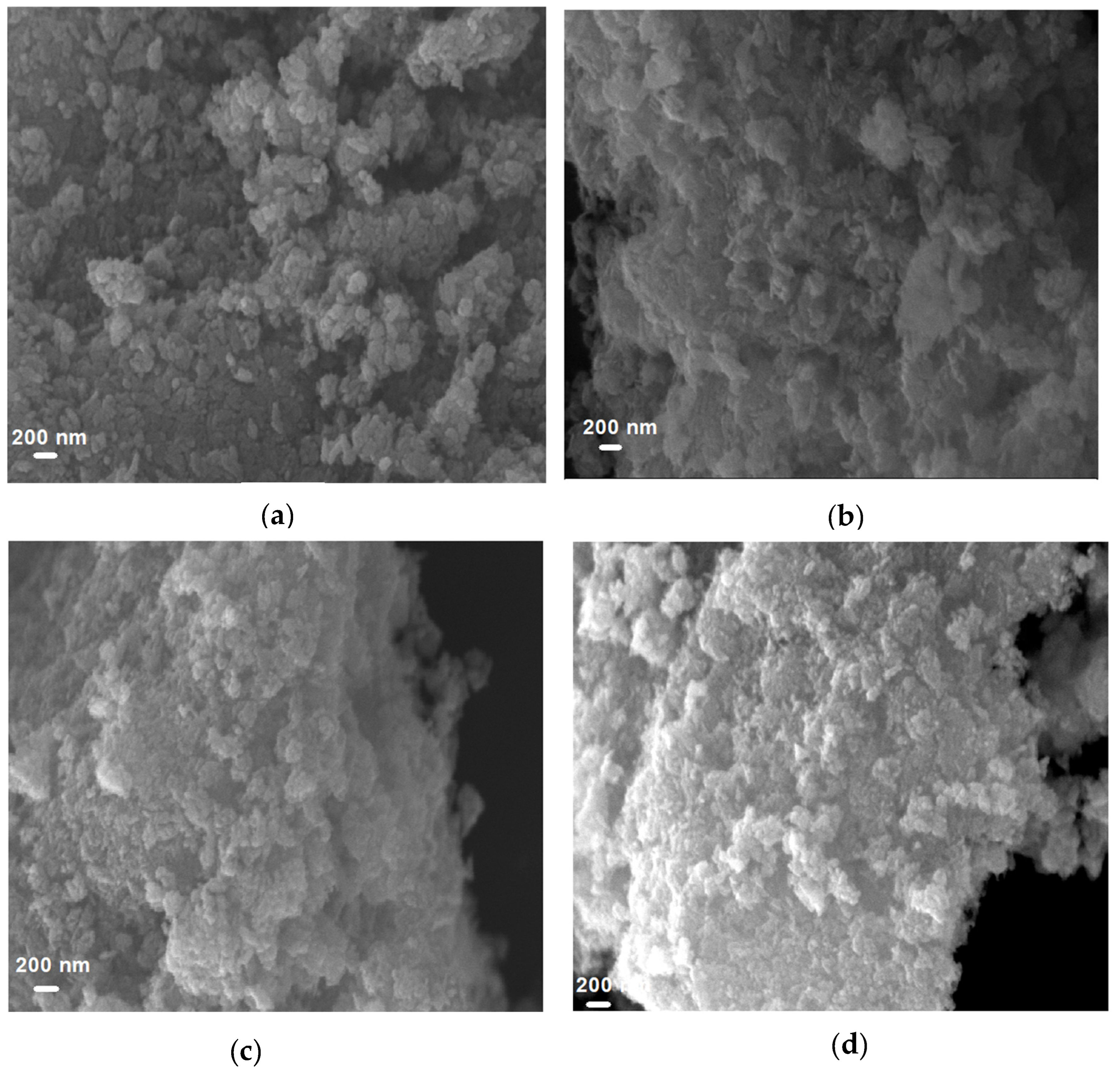
3.1.1. Surface Morphology of CuO

Morphological analysis was performed for the synthesized CuO material with the help of SEM. As shown in Figure 1, it can be observed that larger secondary particles were formed as sponge-like agglomerates of a few microns in size as a consequence of agglomerating sub-micron primary particles for the materials prepared with the concentrations of 0.02 M, 0.03 M, 0.04 M and 0.05 M. This type of microstructural morphology usually forms surfaces that may be beneficial for improving the interfacial properties of the CuO/electrolyte interface. This is because it can lead to enhance contact surface area between the CuO/electrolyte interface, leading to enhance reactions between the electrode and the electrolyte. These favorable morphologies for the electrode material not only decrease the possible volume expansion during the lithiation–delithiation process but also increase the contact area between the CuO/electrolyte interface, thereby shortening the diffusion path for Li-ions [33]. Consequently, they improve the electrochemical performance. In the present study, all these synthesized CuO materials have shown considerably promising electrochemical performance. Nevertheless, the best electrochemical performance was reported for the CuO synthesized at the concentration of 0.03 M. Consequently, this best-performing 0.03 M material was selected for the subsequent in-depth investigations.
The specific surface area of the selected CuO material, in the form of fine powder, was determined using the BET surface area analyzer (Quantichrome Autoflow Bet+ analyzer). For that, the sample was degassed under purging nitrogen gas at a temperature of 70 °C. The selected CuO, synthesized at the concentration of 0.03 M, showed a specific surface area of 36.0 m2/g. This specific surface area, a result of the present study, is considerably higher than those reported for previous morphologies, such as leaf-like nanosheets and sheet-like morphology [15], and hierarchical structures [23]. It shows the capability of the synthesis process used in the present study over the previously reported methods to improve the surface area of the CuO active anode electrode material, as is also evident in SEM analysis. This can definitely cause improvement of CuO/electrolyte morphological interfacial properties. This enhanced electrode–electrolyte contact area can shorten the lithium-ion transport path and enhance the electrochemical performance of LIBs.
XPS analysis was taken for investigating the comprehensive elemental composition and electronic state of the sponge-like CuO. According to the survey spectrum, it shows evidence for the existence of Cu, O and a small amount of carbon (Figure 2a). In Figure 2b, the peaks are attributed to the Cu 2p3/2 (932.2 eV) and Cu 2p1/2 (952.1 eV), respectively, indicating the Cu+2 oxidation state of CuO with the agreement of the previously reported study [24]. The existence of the shake-up satellite peaks at about 942.0 eV and the single satellite peak at 960.9 eV provides evidence of the 3d9 shell of the Cu2+ state. According to the O1s spectra of Figure 2c, two peaks appeared at 528.2 and 529.6 eV, and these peaks can be assigned to O2− in CuO and absorbed oxygen, respectively [32]. According to XPS analysis results, the formation of pure CuO is confirmed.

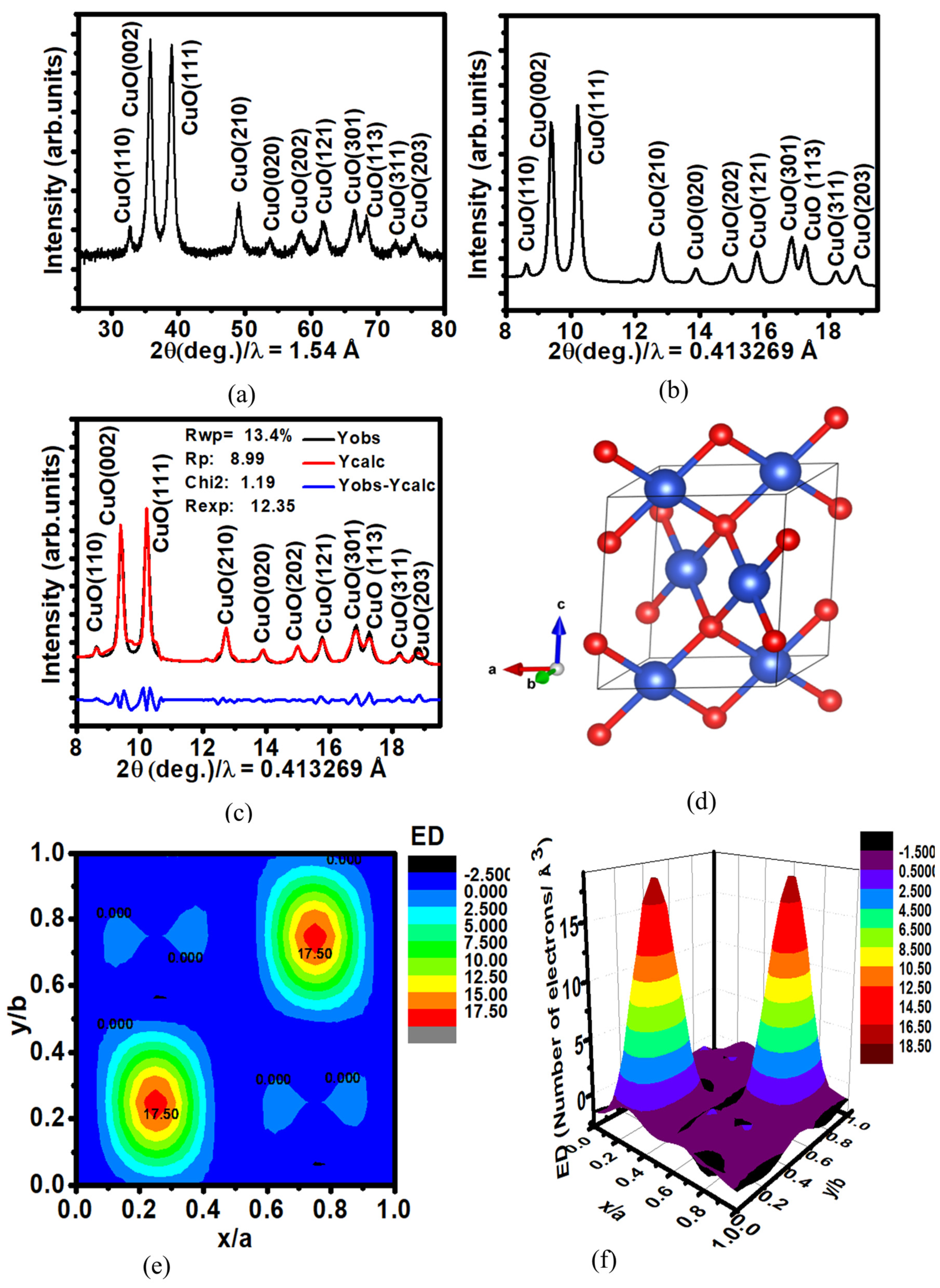
3.1.2. Crystallographic Properties

Figure 3a shows the XRD pattern obtained for the synthesized CuO of 0.03 M concentration by using a laboratory powder X-ray diffractometry. It shows the existence of well-defined diffraction peaks, confirming the significant crystalline nature of the synthesized CuO. The diffraction peaks are shown at 2θ = 32.47°, 35.52°, 38.72°, 48.71°, 53.39°, 58.12°, 61.48°, 66.20°, 68.02°, 72.47° and 75.20°, corresponding to (110), (002), (111), (210), (020) (202) (121), (301), (113), (311) and (203) crystalline planes, respectively [23]. All the diffraction peaks present in Figure 1a can be confined to the monoclinic crystalline structure of CuO (space group C2/c, JCPDS Card No. 48-1548) [29]. Furthermore, there is no evidence for the existence of any residual or secondary phases, such as Cu(OH)2, Cu2O and Cu. Hence, it confirms the capability of the employed synthesis technique for the successful formation of the required crystalline form of CuO.
SXRD technique can reveal more accurate structural information compared to laboratory XRD. Figure 3b displays the SXRD profile obtained for the synthesized CuO material. It shows the existence of reflection peaks at 8.61°, 9.38°, 10.21°, 12.73°, 13.86°, 14.99°, 15.77°, 16.85°, 17.26°, 18.24° and 18.85° related to the crystalline plans of (110), (002), (111), (210), (020), (202), (121), (301), (113), (311) and (203), respectively. The SXRD pattern also does not show any evidence for the presence of residual or secondary phases in the synthesized CuO.
Rietveld refinement was performed using the Fullprof program for further analysis of the XRD patterns. Pseudo-Voigt profile functions were used in order to describe the peak patterns, while linear interpolation was employed for adjusting the background. First, the global parameters, including background, instrument and scaling factors, were adjusted by allowing consequent adjustment of the cell parameters. Sequential refinement of FWHM parameters, shape parameters, preferred orientation and atomic positions were carried out. Further, the Figure 3c shows the Rietveld refinement fitting obtained for the SXRD pattern. Table 1 presents the obtained structural information, including lattice parameter and unit cell volume corresponding to the reported theoretical and experimental values of CuO (a = 4.6586 Å, b = 3.4060 Å, c = 5.1086 Å and β(deg.) = 99.302) [30]. In addition, Figure 3d shows the resultant monoclinic crystal structure derived through the information obtained from Rietveld refinement.
Electron density distribution of the CuO crystal structure is a crucial factor because of its relation to the conversion mechanism reaction during the cycling process. Finally, Figure 3e,f show the 2D and 3D view of the electron density distribution of the CuO crystal structure that resulted from information obtained from Rietveld refinement of XRD analysis (using GFourier-FullProf). The program runs Fourier analyses of the scattering density inside the unit cell of a crystal in any kind of symmetry. GFourier-FullProf uses a Fast Fourier Transform (FFT) subroutine to accelerate the calculation of the following expression:
ρ r = 1 V H F H exp 2 π i H . r
where V is the volume of the unit cell. H is a reciprocal lattice vector, r is a vector position inside the unit cell and F(H) are complex Fourier coefficients used to perform different types of Fourier syntheses. The units of ρ(r) are those of F(H) divided by those of V. For instance, if F(H) are given in electron units (the usual absolute units for X-ray diffraction) and V in Å3, then ρ(r) is calculated as Number-of-Electrons/Å3. It indicates a high electron distribution around Cu atoms that enhances the efficiency of the conversion mechanism reaction during the cycling process of the CuO anode.
The Raman spectrum obtained for the synthesized CuO is shown in Figure 4. The Raman spectrum shows an active Ag + 2Bg Raman mode of CuO. The Ag mode is related to phase rotation. The first Bg mode is related to bending of CuO, and the second Bg mode corresponds to symmetric stretching of oxygen [31]. The Raman spectrum of CuO shows three strong peaks at 277.0 cm−1, 324.0 cm−1 and 610.0 cm−1. They correspond to the characteristic Ag, B1g and B2g modes of CuO with monoclinic crystal symmetry. No evidence exists for active modes related to the presence of residual or secondary phases such as Cu2O, Cu(OH)2 or Cu.

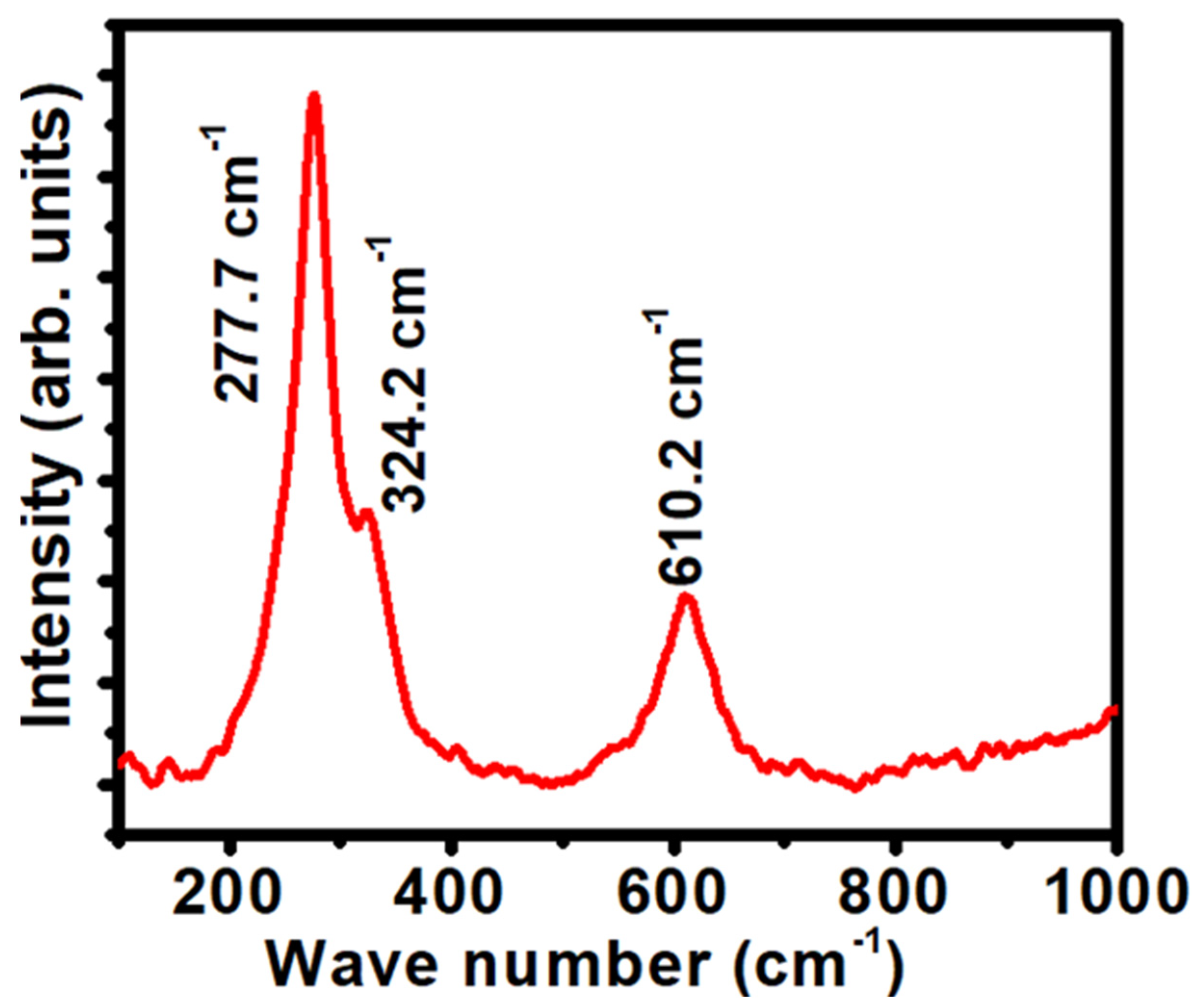
3.1.3. Optical Properties

The diffuse reflectance UV–Visible spectrum of CuO was taken for determining the band gap energy. According to the Kubelka–Munk (K-M) theory, reflectance data were transformed into absorption data mode. Figure 5a shows the plot of [ F R   × h υ ] 2 versus incident photon energy h υ . The band gap energy of CuO is calculated using Tac’s equation through extrapolating the straight line of the plot of [ F R   × h υ ] 2 versus incident photon energy h υ , as shown in Figure 5a. For this study, the calculated band gap energy of CuO was 1.55 eV. Interfacial properties of Cu/CuO are crucial for the electrochemical performance of Li/CuO half-cells due to the semiconducting properties of CuO. For the band diagram shown in Figure 5b, the band gap and electron affinity values of CuO (Eg-CuO) and (χ-CuO) are obtained as 1.55 and 4.07 eV. For the anode applications, copper (Cu) foil is used as a current collector, and it has a metal work function of 4.65 eV [34]. Hence, Schottky contact is constructed at Cu/CuO interface due to the misalignment of work function Cu and Fermi level of CuO, as shown in Figure 5c. The conduction band offset (ΔEV, CuO) is 0.87 eV. This type of Schottky barrier impedes the transfer of elections between Cu/CuO interfaces. Consequently, it reduces the electrochemical performance of CuO electrodes during cycling.

3.1.4. Electrical Properties of CuO Anode Electrode

Figure 6a shows the current–voltage characteristic curves obtained for the CuO electrode in order to study the electronic interfacial properties at the Cu/CuO interface. For the electrode preparation, polymer binders and conductive additives were added to active material. The electronic interfacial properties at the Cu/CuO interface depend on the mass ratio of active material, acetylene black and polyvinylidene fluoride (PVDF) binder. Conductive additives facilitate the electrons moving via the Cu/CuO interface during the cycling process by decreasing internal resistance and polarization within the anode [35]. The CuO electrode was fabricated by mixing CuO electrode material and polyvinylidene fluoride (PVDF) binder together with acetylene black in the mass ratios 80:10:10, 70:10:20 and 60:10:30 in order to determine the optimum ratio to achieve the best performance. The current-voltage characteristics curve reveals the existence of a linear relationship between current and voltage without showing diode-like behavior at the Cu/CuO interface. Hence, it confirms the enhancement in Cu/CuO interfacial properties (formation of Ohmic contact between the Cu/CuO interfaces) that is caused by introducing acetylene black. With the increase in acetylene black, the gradient of the current-voltage characteristic curves decreased, indicating a successful decrement in resistance in the CuO electrode.
Though the addition of a lower amount of acetylene, carbon black increases the active material content in the anode electrode, lessening the number of conductive pathways at the Cu/CuO interface. Hence, it reduces the overall electrochemical performance of the anode electrode. Even though using a high amount of acetylene carbon black in anode electrode preparation can considerably improve its electrical conductivity, it also negatively impacts the electrochemical performance of the anode electrode, with a lesser amount of available active material in the anode electrode. That leads to blocking of the diffusion pathways of Li+, again decreasing the electrochemical performance of the anode electrode [36]. The preliminary studies for this research work showed the best electrochemical performance from a CuO electrode that consisted of polyvinylidene fluoride (PVDF) binder and acetylene black in the mass ratio of 70:10:20. Hence, the CuO electrodes for the proceeding analysis of the present study were fabricated with the above-mentioned optimized mass ratio of 70:10:20.
Figure 6b illustrates a band diagram for the p-type Ohmic contact. It facilitates the electron transfer through the Cu/CuO interface by avoiding the impedance caused by the band shift across the Schottky barriers. Overall, the formation of an ohmic contact between the Cu/CuO interface improves the electrochemical performance of the Li/CuO half-cells. Even though a number of previous studies reported CuO electrode preparation using conductive additives for LIBs, this type of explanation on the interfacial phenomena for the Cu/CuO interface due to adding of conductive additives cannot be found in the literature.
In addition, studying the relative electron energy diagrams is crucial for developing rechargeable batteries. For rechargeable batteries, the energy difference between the lowest unoccupied molecular orbital (LUMO) and the highest occupied molecular orbital (HOMO) of the electrolyte is considered the “window” of the electrolyte. In order to thermodynamically stabilize batteries, it is required to locate the electrode Fermi energy levels EFA (anode) and EFC (cathode) within the window of the electrolyte [37,38]. This limits the open-circuit voltage (Voc) of Li/CuO half-cells. For Li/CuO half-cells, CuO is used as the anode electrode. The Fermi levels of Li and CuO are 2.5 eV and 5.3 eV [39]. Therefore, a schematic diagram of the relative electronic energies in the electrodes can be constructed, as shown in Figure 6c for a Li/CuO half-cell. Theoretically, it has the ability to show the open circuit voltage of 3.02 eV, depending on the Fermi energy levels of CuO. The Fermi energy level of CuO varies according to the synthesizing technique and due to the presence of binders and conductive additives for the slurry preparation.

3.2. Electrochemical Performance

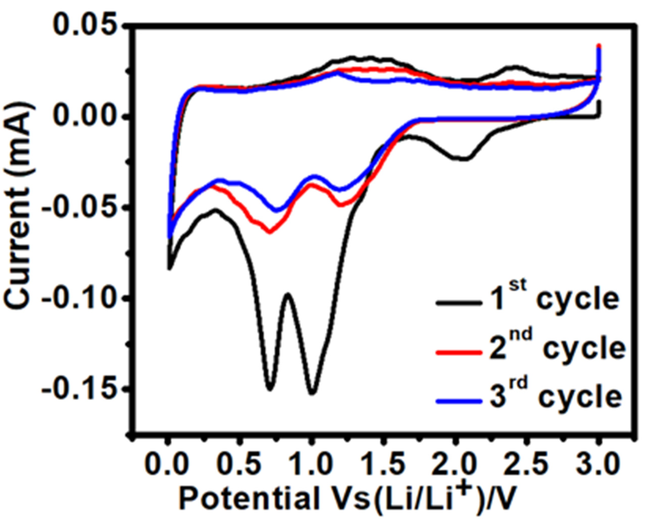
3.2.1. Cyclic Voltammetry (CV)

Figure 7 displays cyclic voltammograms of the CuO electrode obtained at a scan rate of 0.1 mV s−1 for the first three cycles. Three cathodic peaks at 2.06, 1.00 and 0.7 V are observable during the cathodic sweep (lithiation process). These cathodic peaks are associated with the multistep electrochemical reactions leading to the formation of an intermediate solid solution phase, the reduction of CuO to Cu2O, and finally, further reduction to Cu and Li2O [23,24]. The formation of the intermediate phase Cu1−xCuxO1−x/2 (0 < x < 0.4) means that Cu(II) is gradually reduced to Cu(I) in the anode material [23]. Additionally, the oxygen leaves the host structure and forms oxygen ion vacancies. These oxygen ion vacancies are confined by lithium-ion to form the Li2O phase.
During the anodic sweep (delithiation process), two major oxidation peaks are observed around 1.3 V and 2.4 V, respectively, suggesting a multistep electrochemical reaction that involves the oxidation of Cu to Cu2O and finally to CuO [23]. From the second cycle, the cathodic peak potentials are 1.2 and 0.71 V, with a significant decrease in the single peak intensity and integrated area, which indicates an irreversible capacity loss in contrast to the first cathodic sweep. Moreover, the second and third CV curves are nearly overlapped, indicating the expected reversibility of the electrochemical reaction. Continuous sharp cathodic and anodic peaks and smooth CV curves of the CuO electrode evidenced the locating of the Fermi level of the CuO electrode within the electrolyte window.

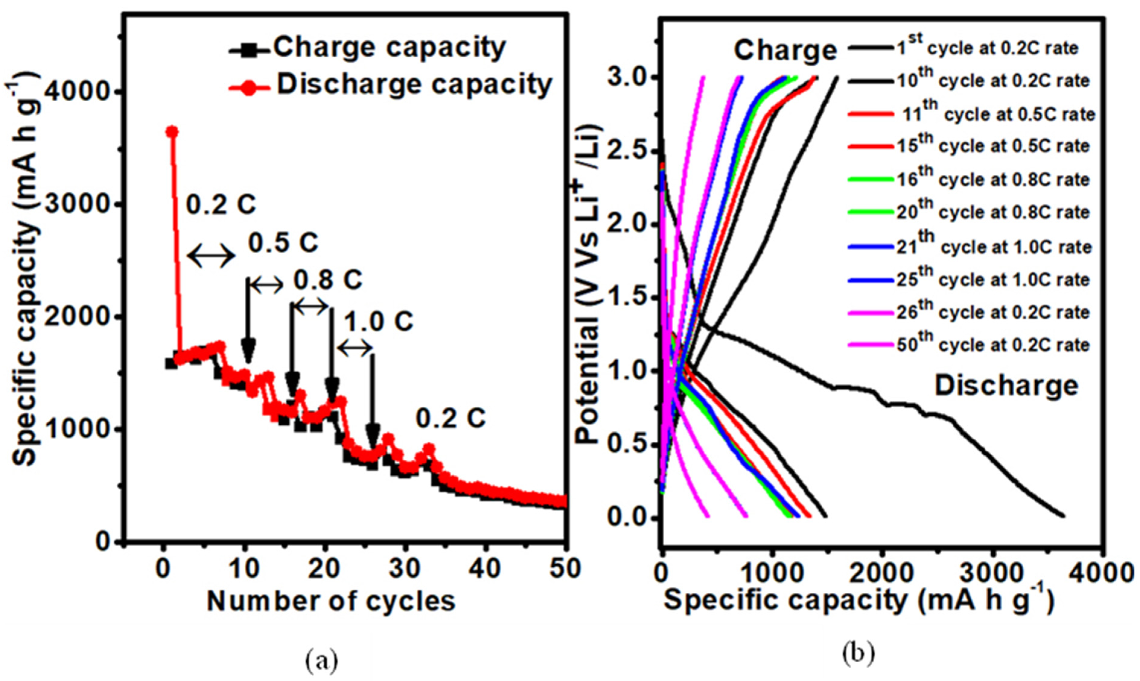
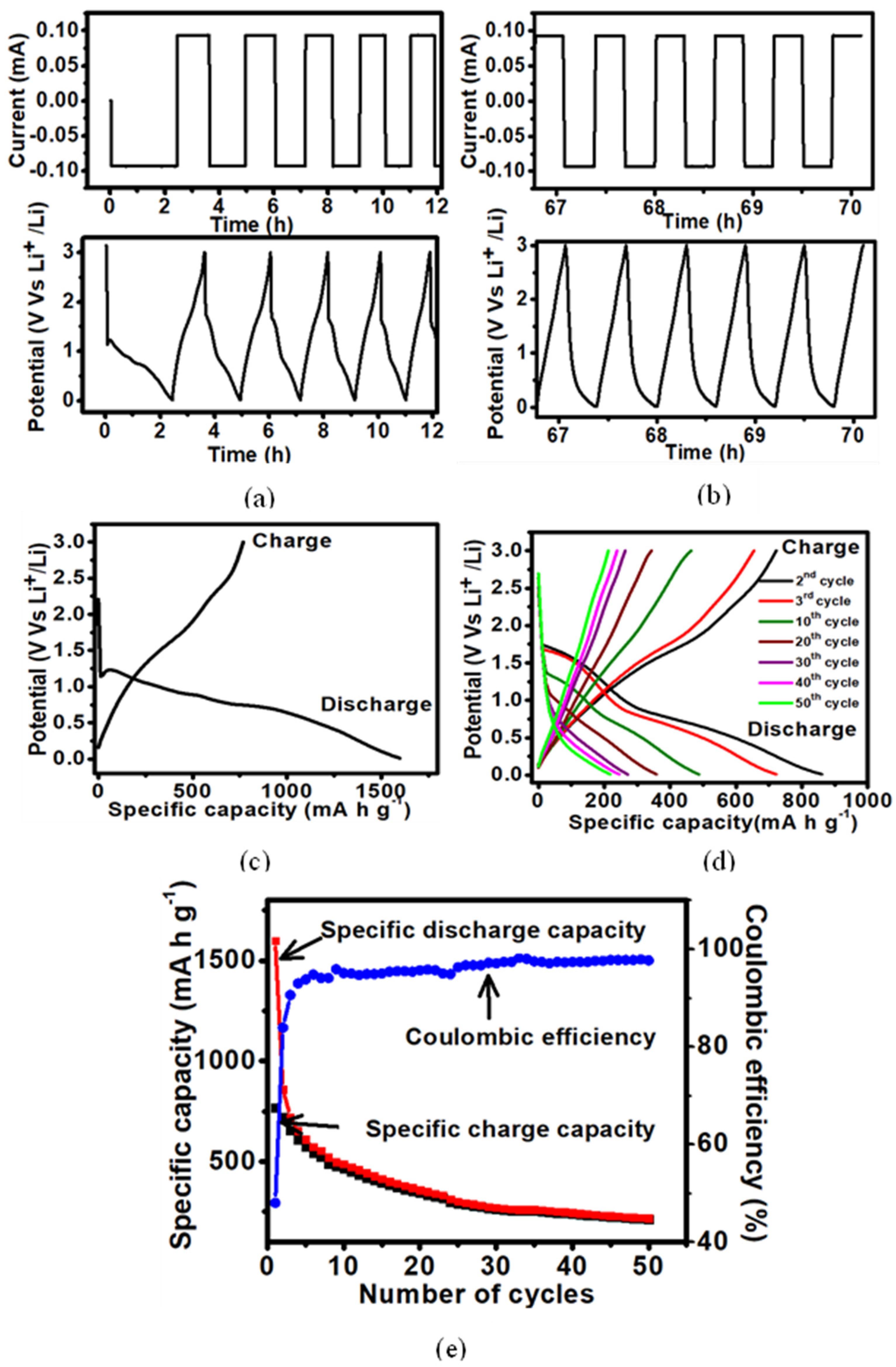
3.2.2. Galvanostatic Cycle Performance

The electrochemical performances reported for the CuO prepared with different concentrations are presented in Table 2. Accordingly, the CuO synthesized with a 0.03 M concertation shows the best performance, with higher first cycle discharge capacity and better cycle-life performance, among the investigated concentrations. Therefore, the proceeding detailed investigations were continued using the CuO prepared with 0.03 M concentration.
The galvanostatic charge-discharge tests of the assembled button cells were performed at room temperature (25 °C) with a constant current rate of 0.2 C (0.018 mA/1.35 mA cm−2) in the voltage range of 0.01 to 3.0 V (vs. Li/Li+). According to Figure 8a,b, there is no indication for current fluctuation during the charging and discharging process, and it can be concluded that a constant current is folowing into the battery over time. Simillarly, during the charging and discharging process, a continuous potential variation can be seen throughout the battery over time, which confirms that the electrode conversion mechanism (electrode kinetics) works better.
Figure 8c displays the discharge–charge potential profile of the first cycle. According to the initial discharge curve, it exhibited three sloping potential ranges of 2.8–1.3 V, 1.31–0.9 V and 0.9–0.01 V. That could be attributable to the reduction of CuO to the intermediate composite copper oxide phase, further reduction to Cu2O and finally decomposition into Cu fine particles and Li2O, respectively, as suggested elsewhere [16,24]. This electrode kinetic behavior is common with all these cyclic voltammogram. In the charge-discharge performance study, the selected CuO electrode exhibited an initial specific discharge capacity of 3371.9 mA h g−1 with a Coulombic efficiency of 40.6%. Despite that, its first cycle-specific charge capacity was 1369.7 mA h g−1. Interestingly, the initial specific discharge and charge capacities that resulted in the present study are higher than those of previously reported studies: CuO nanodisc (971.0/699.0 mA h g−1 at 0.2 C) [40], CuO Nanotube (808.0/582.0 mA h g−1 at 0.1 C) [41], microsphere (1063.9/664.1 mA h g−1 at 0.1 C) [25], CuO nanoplate (966.2/353.4 mA h g−1 at 1.0 C) [42] and nanochain CuO (1002.9/642.1 h g−1 at 0.1C) [16], Pillow-shaped Porous CuO (776.3/374.2 mA h g−1 at 0.1 C) [43] and mulberry-like shape CuO (929.4/546.4 mA h g−1 at 1.0 C) [42].
The theoretically specific capacity of the CuO electrode is regarded as 674 mA h g−1 [15]. Further, the resulting specific capacity of the CuO synthesized in the present study is considerably higher than that of most of those reported for CuO by other research groups. The irreversible capacity loss can be attributed to the formation of SEI during the first discharge process, the reduction of adsorbed constitutes on active material surfaces and the initial formation of lithium oxide [44]. Furthermore, as shown in SEM analysis, the microstructural morphology of CuO consists of a higher surface area, which could enhance the contact area at the CuO/electrolyte interface. For low current rates, charge carriers move slowly, and those carriers have enough time to trap them within the surface. Hence, a large number of lithium ions may be stored at the interface during the first cycle. Consequently, it shows a higher discharge capacity for the initial cycle than its theoretical value of 674 mA h g−1. Figure 8c shows charge-discharge potential curves up to the 50th cycle. In the second cycle, the CuO electrode exhibits a continuous and smooth potential variation, which confirms the stability of the conversion mechanism after the first cycle. The shape and continuity of the curves do not change significantly in the following cycles, indicating good reversibility of the electrochemical reaction even over the 50 cycles.
Figure 8e shows the charge-discharge capacities of the CuO electrode as a function of the number of cycles. The charge-discharge capacities of the CuO electrode gradually decrease with increased cycle number, with a slight fluctuation behavior in specific charge-discharge capacities, as depicted in Figure 8e. However, specific charge-discharge capacities are overlapping each other, indicating the stability of the electrode with the increase in number of cycles. The Coulombic efficiency is significantly improved after the first cycle. Moreover, the irreversible capacity loss decreased to 153.9 mA h g−1 in the second cycle with a significantly increased Coulombic efficiency of 88.9%, indicating that a stable SEI was formed mainly during the first cycle. The specific discharge capacity slightly decreased to 1279.4 mA h g−1 during the third cycle, while subsequent cycles continued to have high Coulombic efficiencies of above 92.6%. After 50 cycles, CuO electrode showed a specific discharge capacity of 442.9 mA h g−1 (Coulombic efficiency of 97.4%), indicating promising cyclic behavior. Interestingly, it accounts for achieving more than 50% of the theoretical specific capacity and considerably better performance in the present study compared to those of previously reported CuO structures: CuO nanodisc (290 mA h g−1 at 0.2 C after 20 cycles) [40], microsphere (429.0 mA h g−1 at 0.1 C after 50 cycles) [25], Pillow-shaped Porous CuO (350.0 mA h g−1 at 0.1 C after 50 cycles) [43] and nanochain CuO (611.9 mA h g−1 at 0.1 C after 30 cycles) [16]. Furthermore, Liu et al. has reported a CuO hierarchical structure that delivered specific discharge capacities of 575.0 mA h g−1 at 1.0 C over 100 cycles and 504.0 mA h g−1 at 2.0 C over 100 cycles, better than the current study. However, in this present study, CuO was synthesized by a simple, inexpensive, non-toxic, high-safety, more environmental chemical precipitation technique. This was achieved without using high-toxicity or high-expense chemicals, expensive instruments and multistep processes. Even though the specific discharge capacity decreased from 3371.9 mA h g−1 to 442.9 mA h g−1 after the 50 cycles, CuO has shown good electrochemical performance as a very promising anode electrode material for the anode application of LIBs.
Another outstanding property related to CuO electrodes is their rate capability with cycle numbers. The discharge capacities are shown in Figure 9a as a function of the number of cycles at different current rates (0.2 C, 0.5 C, 0.8 C, 1.0 C and 0.2 C). The CuO electrodes delivered a specific discharge capacity of 1482.8 mA h g−1 after the 10th cycle at a rate of 0.2 C with a Coulombic efficiency of 94.3%. In the 15th cycle, the specific discharge capacity was 1168.7 mA h g−1 at a rate of 0.5 C with an irreversible capacity loss of 79.1 mA h g−1 and Coulombic efficiency of 94.3%. Then, the discharge capacity continuously decreased to 1163.4 mA h g−1 after the 20th cycle at the rate of 0.8 C, and it further decreased down to 764.9 mA h g−1 after another 5 cycles at a rate of 1.0 C. Importantly, when the current rate was returned to the initial current rate of 0.2 C, the CuO electrode delivered a specific discharge capacity of 762.9 mA h g−1 for the 26th cycle and 365.6 mA h g−1 (Coulombic efficiency of about 90.3%) for the 50th cycle (Coulombic efficiency of about 92.4%), indicating good reversibility and stability of the electrode during cycling. But a slight fluctuation in specific charge-discharge capacities can be observable during the time the current rates change, as highlighted in Figure 9a, indicating less stability of the synthesized CuO electrode for different current rates. However, after 40 cycles, the specific charge-discharge capacities are overlapping each other, indicating a higher stability of the electrode with the increase in number of cycles. According to Figure 9b, there is no significant change in the shape and continuity of the successive charge-discharge cycles, and it indicates good cycling stability of the CuO electrode.
Figure 10a,b present the outcome of the galvanostatic charge-discharge tests of the CuO electrode at the 1.0 C (0.096 mA/7.23 mA cm−2) current rate in the voltage range of 0.01–3.0 V (versus Li/Li+) at room temperature (25 °C). It evidences the following of a constant current through the battery during the charging and discharging process with time, without any fluctuations. It also shows a continuous potential variation through the battery with time during the charging and discharging process, evidencing a well-performing conversion mechanism of the electrode (electrode kinetics) at a high current rate.
Figure 10b displays the discharge-charge potential profile of the first cycle. The initial specific discharge capacity of the CuO electrode was 1598.5 mA h g−1. However, the first cycle specific charge capacity was 767.7 mA h g−1 and the Coulombic efficiency was 48%. As explained in the cycling performance at 0.2 C, the higher initial specific discharge capacity and lower Coulombic efficiency confirm the formation of a stable SEI even at higher current rates. Figure 10c shows charge-discharge potential profiles of the CuO electrode up to the 50th cycle. For the second cycle, the CuO electrode shows continuous and smooth sloping potentials. It confirms the stability of the conversion mechanism after the first cycle. The shapes and continuity of the charge-discharge curves remain relatively consistent in the subsequent cycles, implying a good reversibility of the electrochemical reaction up to the 50th cycle. Figure 10d shows the charge-discharge capacities of the CuO electrode as a function of number of cycles. The specific discharge capacity of the second cycle was 860 mA h g−1 with an irreversible capacity loss of 138.1 mA h g−1 and a Coulombic efficiency of 83.9%. The specific discharge capacity was 1279.4 mA h g−1 during the third cycle, while subsequent cycles continued to have high Coulombic efficiencies of over 90.6%. It can be seen that the capacities gradually decreased with the increase in the cycle number without any significant fluctuation of specific charge-discharge capacities. Moreover, it displayed a specific discharge capacity of 217.6 mA h g−1 and an interestingly lower irreversible capacity of 5.0 mA h g−1, with a significantly high Coulombic efficiency of about 98.0% even after 50 cycles, indicating good reversibility and stability of the electrode during cycling at a high current rate.
Further, Figure 10e displays Coulombic efficiency profiles of the CuO electrode as a function of cycle numbers. Even though the prepared CuO electrode showed a lower Coulombic efficiency of 48.0% for the first cycle, higher Coulombic efficiencies have been reported for the subsequent cycles, confirming a proper transferring of Li+ and electrons in between the anode and cathode at a high current rate. Also, the CuO electrode exhibits stable coulomb efficiencies with the number of cycles up to the 50th cycle.

4. Conclusions

In conclusion, the CuO material synthesized at the Cu(NO3)2 concentration of 0.03 M by the simple and convenient chemical precipitation technique in the present study showed the best electrochemical performance for a promising anode electrode material for LIB. SEM analysis reveals the occurrence of a sponge-like microstructure in the synthesized powder particles. The XPS, XRD, SXRD and Raman spectrum confirmed the formation of the required phase of CuO without any residual or secondary phases. The electron density distribution of the CuO crystal structure was obtained through the XRD Rietveld refinement. It revealed that the highest distribution of electrons occurred around Cu atoms and enhanced the productivity of the conversion mechanism during the cycling process. The band gap of sponge-like CuO was determined to be 1.55 eV. Further, the current-voltage characterization curves indicate Ohmic behavior at the Cu/CuO interface for the addition of acetylene black in 10 wt%, 20 wt% and 30 wt%. The electrodes fabricated with synthesized CuO as the active material with polyvinylidene fluoride (PVDF) binder and acetylene black as the conductivity enhancer in the mass ratio of 70:10:20, respectively, resulted in the best electrochemical performance, indicating that 20 wt.% was the optimum level for acetylene black. The electrode fabricated with CuO synthesized with a 0.03 M concentration showed a high initial specific discharge capacity of 3371.9 mA h g−1 at a rate of 0.2 C. Further, this electrode showed a specific discharge capacity of 442.9 mA h g−1 with a Coulombic efficiency of 97.4% after 50 cycles. Moreover, by demonstrating good cycle performance at different current rates, the fabricated CuO anode electrode reported its high potentiality with a good rate capability, reversibility and stability. Furthermore, at a rate of 1.0 C, the initial specific discharge capacity of the CuO electrode was reported to be 1598.5 mA h g−1 with a Coulombic efficiency of 48%. It displayed a specific discharge capacity of 217.6 mA h g−1 with a significantly high Coulombic efficiency of about 98.0%, even after 50 cycles, for the rate of 1.0 C. Altogether, this study, based on a sponge-like microstructured CuO that was synthesized at a Cu(NO3)2 concentration of 0.03 M by a simple, cost-effective, non-toxic and environmentally friendly chemical precipitation technique, reveals a promising electrochemical performance for the anode application of LIBs.

Author Contributions

Conceptualization, W.T.R.S.F., T.H.N.G.A. and H.W.M.A.C.W.; Methodology, W.T.R.S.F., T.H.N.G.A. and H.W.M.A.C.W.; Software, W.T.R.S.F.; Formal analysis, W.T.R.S.F., T.H.N.G.A., K.M.D.C.J., L.S.R.K. and R.P.W.; Investigation, W.T.R.S.F., T.H.N.G.A. and H.W.M.A.C.W.; Resources, O.S. (O. Seo), K.O., O.S. (O. Sakata) and H.W.M.A.C.W.; Data curation, W.T.R.S.F., K.M.D.C.J., L.S.R.K., O.S. (O. Seo), K.O., O.S. (O. Sakata) and R.P.W.; Writing—original draft, W.T.R.S.F., T.H.N.G.A. and H.W.M.A.C.W.; Writing—review & editing, T.H.N.G.A., K.M.D.C.J., L.S.R.K., O.S. (O. Seo), K.O., O.S. (O. Sakata), R.P.W. and H.W.M.A.C.W.; Supervision, T.H.N.G.A., H.W.M.A.C.W.; Project administration, H.W.M.A.C.W. Funding acquisition, H.W.M.A.C.W. All authors have read and agreed to the published version of the manuscript.

Funding

This research was funded by National Center for Advanced Battery Research, National Institute of Fundamental Studies, Kandy 20000, Sri Lanka.

Institutional Review Board Statement

Not applicable.

Informed Consent Statement

Not applicable.

Data Availability Statement

Data are contained within the article.

Acknowledgments

Members of the National Centre for Advanced Battery Research of the National Institute of Fundamental Studies, Sri Lanka, are acknowledged. The authors are grateful for the facilities and other support given by the synchrotron XRD measurements were carried out at SPring-8 with the approval of the Japan Synchrotron Radiation Research Institute (JASRI) under proposal No. 2021B1761, No. 2022B1658 and No. 2023A1541.

Conflicts of Interest

The authors declare no conflict of interest.

References

  1. Schomburg, F.; Heidrich, B.; Wennemar, S.; Drees, R.; Roth, T.; Kurrat, M.; Heimes, H.; Jossen, A.; Winter, M.; Cheong, J.Y.; et al. Lithium-ion battery cell formation: Status and future directions towards a knowledge-based process design. Energy Environ. Sci. 2024, 17, 2686–2733. [Google Scholar] [CrossRef]
  2. Stephan, A.K. The Age of Li-Ion Batteries. Joule 2019, 3, 2583–2584. [Google Scholar] [CrossRef]
  3. Winslow, K.M.; Laux, S.J.; Townsend, T.G. A review on the growing concern and potential management strategies of waste lithium-ion batteries. Resour. Conserv. Recycl. 2018, 129, 263–277. [Google Scholar] [CrossRef]
  4. Zhang, H.; Yang, Y.; Ren, D.; Wang, L.; He, X. Graphite as anode materials: Fundamental mechanism, recent progress and advances. Energy Storage Mater. 2021, 36, 147–170. [Google Scholar] [CrossRef]
  5. Winowatan, P.W.; Selwyn, S.; Priyono, B.; Syahrial, A.Z. Enhancing battery performance of Li4Ti5O12 nanorod synthesized by hydrothermal method with Sn addition as anode material for lithium-ion battery. J. King Saud Univ. Eng. Sci. 2021, 33, 396–403. [Google Scholar] [CrossRef]
  6. Yi, X.; Qi, G.; Liu, X.; Depcik, C.; Liu, L. Challenges and strategies toward anode materials with different lithium storage mechanisms for rechargeable lithium batteries. J. Energy Storage 2024, 95, 112480. [Google Scholar] [CrossRef]
  7. Subalakshmi, P.; Sivashanmugam, A. CuO nano hexagons, an efficient energy storage material for Li- ion battery appli-cation. J. Alloys Compd. 2017, 690, 523–531. [Google Scholar] [CrossRef]
  8. Poizot, P.; Laruelle, S.; Grugeon, S.; Dupont, L.; Tarascon, J.-M. Nano-sized transition-metal oxides as negative-electrode materials for lithium-ion batteries. Nature 2000, 407, 496–499. [Google Scholar] [CrossRef]
  9. Zhang, W.; Wang, H.; Zhang, Y.; Yang, Z.; Wang, Q.; Xia, J.; Yang, X. Facile microemulsion synthesis of porous CuO nanosphere film and its application in lithium ion batteries. Electrochimica Acta 2013, 113, 63–68. [Google Scholar] [CrossRef]
  10. Wong, W.T.K.S.; Zhuk, S.; Masudy, P.S.; Dalapati, G.K. Current Status and Future Prospects of Copper Oxide Heterojunction Solar Cells. Materials 2016, 9, 271. [Google Scholar] [CrossRef]
  11. Morariu, M.I.; Nicolaescu, M.; Hulka, I.; Duţeanu, N.; Orha, C.; Lăzău, C.; Bandas, C. Fabrication of Cu2O/CuO Nanowires by One-Step Thermal Oxidation of Flexible Copper Mesh for Supercapacitor Applications. Batteries 2024, 10, 246. [Google Scholar] [CrossRef]
  12. Renganathan, B.; Gopakumar, C.; Priya, A.K.; Rao, S.K.; Sastikumar, D.; Silambarasan, M.; Kannapiran, N. Optimizing Gas Sensing Performance of CuO Nanoparticles via Sol-Gel Synthesis Approach for Efficient Detection of Ammonia Gas. Mater. Res. Bull. 2023, 170, 112556. [Google Scholar] [CrossRef]
  13. Zedan, A.F.; Mohamed, A.T.; El-Shall, M.S.; AlQaradawi, S.Y.; AlJaber, A.S. Tailoring the reducibility and catalytic activity of CuO nanoparticles for low temperature CO oxidation. RSC Adv. 2018, 8, 19499–19511. [Google Scholar] [CrossRef] [PubMed]
  14. Yuan, W.; Ye, Y.; Yang, Y.; Zhang, X.; Pan, B.; Peng, Z.; Wu, M.; Qiu, Z.; Wang, C.; Yuan, Y.; et al. CuO nanoflowers/copper fiber felt integrated porous electrode for lithium-ion batteries. Sci. China Technol. Sci. 2020, 63, 2423–2434. [Google Scholar] [CrossRef]
  15. Deng, Z.; Ma, Z.; Li, Y.; Li, Y.; Chen, L.; Yang, X.; Wang, H.-E.; Su, B.-L. Boosting Lithium-Ion Storage Capability in CuO Nanosheets via Synergistic Engineering of Defects and Pores. Front. Chem. 2018, 6, 428. [Google Scholar] [CrossRef]
  16. Wang, P.; Gou, X.-X.; Xin, S.; Cao, F.-F. Facile synthesis of CuO nanochains as high-rate anode materials for lithium-ion batteries. New J. Chem. 2019, 43, 6535–6539. [Google Scholar] [CrossRef]
  17. Zhang, W.; Ma, G.; Gu, H.; Yang, Z.; Cheng, H. A new lithium-ion battery: CuO nanorod array anode versus spinel LiNi0.5Mn1.5O4 cathode. J. Power Sources 2015, 273, 561–565. [Google Scholar] [CrossRef]
  18. Qian, Y.; Niehoff, P.; Zhou, D.; Adam, R.; Mikhailova, D.; Pyschik, M.; Börner, M.; Klöpsch, R.; Rafaja, D.; Schumacher, G.; et al. Investigation of nano-sized Cu(ii)O as a high capacity conversion material for Li-metal cells and lithium-ion full cells. J. Mater. Chem. A 2017, 5, 6556–6568. [Google Scholar] [CrossRef]
  19. Jose, A.S.; Gangaja, B.; Nair, S.; Santhanagopalan, D. Influence of cobalt concentration on CuO nanoplates morphology and its superior performance as Li–ion battery anode. Mater. Res. Express 2019, 6, 125543. [Google Scholar] [CrossRef]
  20. Meng, J.; Yang, Z.; Chen, L.; Qin, H.; Cui, F.; Jiang, Y.; Zeng, X. Energy storage performance of CuO as a cathode material for aqueous zinc ion battery. Mater. Today Energy 2020, 15, 100370. [Google Scholar] [CrossRef]
  21. Zhang, X.; Zhang, G.; Wang, S.; Li, S.; Jiao, S. Porous CuO microsphere architectures as high-performance cathode materials for aluminum-ion batteries. J. Mater. Chem. A 2018, 6, 3084–3090. [Google Scholar] [CrossRef]
  22. Gangaja, B.; Chandrasekharan, S.; Vadukumpully, S.; Nair, S.V.; Santhanagopalan, D. Surface chemical analysis of CuO nanofiber composite electrodes at different stages of lithiation/delithiation. J. Power Sources 2017, 340, 356–364. [Google Scholar] [CrossRef]
  23. Wang, H.; Liang, T.; Yu, X.; Zhao, W.; Xu, R.; Wang, D.; Liu, Y. Hydrothermal synthesis of well-crystallized CuO hierarchical structures and their direct application in high performance lithium-ion battery electrodes without further calcination. RSC Adv. 2016, 6, 96882–96888. [Google Scholar] [CrossRef]
  24. Hu, L.; Yang, Z.; Li, H.; Yang, X.; Li, J.; Wang, P.; Jin, C.; Zhang, C. Three-dimensional clusters of peony-shaped CuO nanosheets as a high-rate anode for Li-ion batteries. RSC Adv. 2021, 11, 10760–10766. [Google Scholar] [CrossRef]
  25. Wang, C.; Higgins, D.; Wang, F.; Li, D.; Liua, R.; Liu, G.; Li, N.; Li, Q.; Xu, H.; Wu, G. Controlled synthesis of micro/nanostructured CuO anodes for lithium-ion batteries. Nano Energy 2014, 9, 334–344. [Google Scholar] [CrossRef]
  26. Xiang, J.; Tu, J.; Zhang, L.; Zhou, Y.; Wang, X.; Shi, S. Self-assembled synthesis of hierarchical nanostructured CuO with various morphologies and their application as anodes for lithium ion batteries. J. Power Sources 2010, 195, 313–319. [Google Scholar] [CrossRef]
  27. Patil, A.S.; Lohar, G.M.; Fulari, V.J. Structural, morphological, optical and photoelectrochemical cell properties of copper oxide using modified SILAR method. J. Mater. Sci. Mater Electron. 2016, 27, 9550–9557. [Google Scholar] [CrossRef]
  28. Xiao, A.; Zhou, S.; Zuo, C.; Zhuan, Y.; Ding, X. Improved electrochemical performances of CuO nanotube array prepared via electrodeposition as anode for lithium ion battery. Mater. Res. Bull. 2015, 70, 795–798. [Google Scholar] [CrossRef]
  29. Sahay, R.; Kumar, P.S.; Aravindan, V.; Sundaramurthy, J.; Ling, W.C.; Mhaisalkar, S.G.; Ramakrishna, S.; Madhavi, S. High Aspect Ratio Electrospun CuO Nanofibers as Anode Material for Lithium-Ion Batteries with Superior Cycleability. J. Phys. Chem. C 2012, 116, 18087–18092. [Google Scholar] [CrossRef]
  30. Chauhan, A.; Verma, R.; Batoo, K.M.; Kumari, S.; Kalia, R.; Kumar, R.; Hadi, M.; Raslan, E.H.; Imran, A. Structural and optical properties of copper oxide nanoparticles: A study of variation in structure and antibiotic activity. J. Mater. Res. 2021, 36, 1496–1509. [Google Scholar] [CrossRef]
  31. Dar, M.; Ahsanulhaq, Q.; Kim, Y.; Sohn, J.; Kim, W.; Shin, H. Versatile synthesis of rectangular shaped nanobat-like CuO nanostructures by hydrothermal method; structural properties and growth mechanism. Appl. Surf. Sci. 2009, 255, 6279–6284. [Google Scholar] [CrossRef]
  32. Rath, P.C.; Patra, J.; Saikia, D.; Mishra, M.; Tseng, C.-M.; Chang, J.-K.; Kao, H.-M. Comparative Study on the Morphology-Dependent Performance of Various CuO Nanostructures as Anode Materials for Sodium-Ion Batteries. ACS Sustain. Chem. Eng. 2018, 6, 10876–10885. [Google Scholar] [CrossRef]
  33. Zhang, R.; Liu, J.; Guo, H.; Tong, X. Synthesis of CuO nanowire arrays as high-performance electrode for lithium ion batteries. Mater. Lett. 2015, 139, 55–58. [Google Scholar] [CrossRef]
  34. Michaelson, H.B. The work function of the elements and its periodicity. J. Appl. Phys. 1977, 48, 4729–4733. [Google Scholar] [CrossRef]
  35. Mohanty, D.; Chang, M.-J.; Hung, I.-M. The Effect of Different Amounts of Conductive Carbon Material on the Electrochemical Performance of the LiFePO4 Cathode in Li-Ion Batteries. Batteries 2023, 9, 515. [Google Scholar] [CrossRef]
  36. Tsai, S.-H.; Tsou, Y.-L.; Yang, C.-W.; Chen, T.-Y.; Lee, C.-Y. Applications of different nano-sized conductive materials in high energy density pouch type lithium ion batteries. Electrochimica Acta 2020, 362, 137166. [Google Scholar] [CrossRef]
  37. Hausbrand, R. Electronic energy levels at Li-ion cathode-liquid electrolyte interfaces: Concepts, experimental insights, and perspectives. J. Chem. Phys. 2020, 152, 180902. [Google Scholar] [CrossRef]
  38. Goodenough, J.B.; Kim, Y. Challenges for Rechargeable Li Batteries. Chem. Mater. 2010, 22, 587–603. [Google Scholar] [CrossRef]
  39. Annathurai, S.; Chidambaram, S.; Baskaran, B.; Prasanna, V.G.K.D. Green Synthesis and Electrical Properties of p-CuO/n-ZnO Heterojunction Diodes. J. Inorg. Organomet. Polym. Mater. 2019, 29, 535–540. [Google Scholar] [CrossRef]
  40. Seo, S.-D.; Jin, Y.-H.; Lee, S.-H.; Shim, H.-W.; Kim, D.-W. Low-temperature synthesis of CuO-interlaced nanodiscs for lithium ion battery electrodes. Nanoscale Res. Lett. 2011, 6, 397. [Google Scholar] [CrossRef]
  41. Lee, J.; Choi, S.; Park, S. A Simple Fabrication of Interconnected CuO Nanotube Electrodes for High-Performance Lithium-Ion Batteries. Chem.–Asian J. 2013, 8, 1377–1380. [Google Scholar] [CrossRef] [PubMed]
  42. Mohapatra, S.; Nair, S.V.; Santhanagopalan, D.; Rai, A.K. Nanoplate and mulberry-like porous shape of CuO as anode materials for secondary lithium ion battery. Electrochimica Acta 2016, 206, 217–225. [Google Scholar] [CrossRef]
  43. Wan, M.; Jin, D.; Feng, R.; Si, L.; Gao, M.; Yue, L. Pillow-shaped porous CuO as anode material for lithium-ion batteries. Inorg. Chem. Commun. 2011, 14, 38–41. [Google Scholar] [CrossRef]
  44. Wu, R.; Qian, X.; Yu, F.; Liu, H.; Zhou, K.; Wei, J.; Huang, Y. MOF-templated formation of porous CuO hollow octahedra for lithium-ion battery anode materials. J. Mater. Chem. A 2013, 1, 11126–11129. [Google Scholar] [CrossRef]
Figure 1. SEM images of sponge-like CuO synthesized with different concentrations of (a) 0.02 M, (b) 0.03 M, (c) 0.04 M and (d) 0.05.
Coatings 15 00467 g001
Figure 2. (a) The survey of the XPS spectrum of the sponge-like CuO powder (0.03 M). (b) The Cu 2p region of the XPS spectrum of the sponge-like CuO powder (0.03 M). (c) The O 1s region of the XPS spectrum of the sponge-like CuO powder (0.03 M).
Coatings 15 00467 g002
Figure 3. Outcome of XRD and SXRD analyses related to the CuO powder of 0.03M concentration; (a) laboratory XRD pattern; (b) SXRD; (c) Rietveld refinement of XRD pattern; (d) monoclinic crystal structure of CuO derived from Rietveld refinement; (e) 2D view of electron density distribution; (f) 3D view of electron density distribution.
Coatings 15 00467 g003
Figure 4. Raman spectrum obtained for sponge-like CuO powder (0.03 M).
Coatings 15 00467 g004
Figure 5. (a) Plot (F(R)hν)2 as a function of photon energy of sponge-like CuO powder (0.03 M). (b) Energy band diagram before formation of the junction Cu/CuO interface. (c) Energy band diagram after formation of the junction.
Coatings 15 00467 g005
Figure 6. (a) Current-voltage characterization for the sponge-like CuO O (0.03 M) electrodes. (b) Band diagram at Cu/CuO interface due to adding 10 wt%, 20 wt% and 30 wt% acetylene black. (c) Schematic energy diagram for Li/CuO half-cells.
Coatings 15 00467 g006
Figure 7. Cyclic voltammograms of sponge-like CuO (0.03 M) electrode from 0.01 to 3.0 V (versus Li+/Li) at a scan rate of 0.1 mV s−1.
Coatings 15 00467 g007
Figure 8. The outcome of the galvanostatic charge–discharge tests performed for assembled coin cells at a constant current rate of 0.2 °C in the voltage range of 0.01–3.0 V (versus Li/Li+) up to the 50th cycle. (a) The galvanostatic charge-discharge tests of the first 5 cycles. (b) The galvanostatic charge-discharge tests of the last 5 cycles. (c) Charge-discharge potential profile of CuO electrode at a rate of 0.2 °C for the 1st cycle. (d) Charge-discharge potential profiles of CuO electrode at a rate of 0.2 °C up to the 50th cycle. (e) Cycle performance versus cycle number of CuO electrode at a rate of 0.2 °C up to the 50th cycle.
Coatings 15 00467 g008
Figure 9. (a) Cycle performance versus number of cycles obtained on the CuO electrode at a rate of 0.2 C, 0.5 C, 0.8 C, 1 C and 0.2 C up to the 50th cycle. (b) Charge-discharge potential profiles of CuO electrode between the voltage range of 0.01 and 3 V at different rates of 0.2 C, 0.5 C, 0.8 C, 1 C and 0.2 C.
Coatings 15 00467 g009
Figure 10. The galvanostatic charge-discharge tests were performed for assembled coin cells at a constant current rate of 1.0 C in the voltage range of 0.01–3.0 V (versus Li/Li+) up to 50th cycle. (a): The galvanostatic charge-discharge tests for first 5 cycles. (b): The galvanostatic charge-discharge tests for last 5 cycles. (c) Charge-discharge potential profile of CuO electrode for the 1st cycle. (d) Charge-discharge potential profiles of CuO electrode at a rate of 0.2 C up to the 50th cycle. (e) Cycle performance versus cycle number of CuO electrode at a rate of 0.2 C up to the 50th cycle.
Coatings 15 00467 g010
Table 1. Structural parameters derived from the Rietveld refinement.
Structural Parameters of CuO
Space groupC12/c1
a (Å)4.6829
b (Å)3.4149
c (Å)5.1346
Volume (Å)381.0246
α(deg.)90
β(deg.)99.324
γ(deg.)90
Density (g/cm3)6.856
Atom parameters of Cu
x0.25000
y0.25000
z0.00000
Atom parameters of O
x0.00000
y0.91556
z0.75000
Refinement details
χ21.19
Rp8.99
Rwp13.4
Rexp12.35
Table 2. Specific discharge and charge capacities reported for the CuO synthesized with the concentrations of 0.001 M, 0.02 M, 0.03 M, 0.04 M, 0.05 M and 0.1 M.
ConcentrationDischarge Capacity for the First Cycle (mA h g−1)Charge Capacity for the First Cycle
(mA h g−1)
Discharge Capacity for the 50th Cycle
(mA h g−1)
Charge Capacity for the 50th Cycle
(mA h g−1)
0.001 M889.5192.778.477.5
0.02 M1366451.7232.3222.9
0.03 M3371.91369.7442.9431.5
0.04 M27391625.7213.6199.8
0.05 M2009.9733.6196.5210.1
0.1 M842.2105.8209.8198.9
Disclaimer/Publisher’s Note: The statements, opinions and data contained in all publications are solely those of the individual author(s) and contributor(s) and not of MDPI and/or the editor(s). MDPI and/or the editor(s) disclaim responsibility for any injury to people or property resulting from any ideas, methods, instructions or products referred to in the content.

