Abstract
In this work, two alloys of Ni35Al30(FeCo)25Cr10-xMox (x = 0, 5) were prepared via the vacuum arc melting method, and the effects of Mo on the microstructure, mechanical properties, and friction and wear properties of the alloys were investigated. The addition of Mo improved the mechanical properties, wear resistance, and corrosion resistance of the alloy system. With the addition of trace amounts of Mo, the precipitate phase of the alloys transformed from spherical to acicular and plate-like. The precipitated phases in a co-lattice relationship with the matrix allow for a substantial increase in the strength of the alloy at both room and elevated temperatures without a significant loss of plasticity. Ni35Al30(FeCo)25Cr5Mo5 has excellent mechanical properties, with a hardness of 558.2 HV; a yield strength of 1320 MPa at 600 °C; and a yield strength of 537 MPa at 850 °C. As the temperature increased, the wear mechanism changed from abrasive wear to adhesive wear. At 600 °C, Ni35Al30(FeCo)25Cr5Mo5 had the lowest wear rate of 1.78 × 10⁻⁵ (mm3/Nm). The precipitated phases, which have high hardness and maintain a conformal interface with the matrix, play an important role in slowing delamination wear, keeping the wear rate of this alloy low at both room and high temperatures. Electrochemical experiments on the two alloys at room temperature revealed that Ni35Al30(FeCo)25Cr5Mo5 exhibited excellent resistance to pitting, with a pitting potential of 0.016 V.
1. Introduction
NiAl alloys have the advantages of low density, high melting points, high thermal conductivity, etc., and are thus promising high-temperature structural materials [1]. However, the practical application of NiAl alloys is limited by their insufficient plasticity under ambient conditions and insufficient mechanical properties in high-temperature environments [2]. To enhance the mechanical properties of NiAl, researchers have employed various methods to develop a series of NiAl-based alloys and composites [3,4,5]. However, exploration of the strength–plasticity balance of NiAl alloys has not yet produced tangible results. High-entropy alloys (HEAs), as major element alloys [6,7,8], break through the traditional alloy design ideas and exhibit excellent comprehensive performance, including outstanding mechanical properties [9,10], significant wear resistance [11,12], excellent corrosion resistance performance [13,14] and excellent high-temperature stability [15,16], and have become a research hotspot in the field of materials science. Therefore, this study considered the design concept of a multicomponent alloy to design a novel NiAl-based HEA.
Strengthening mechanisms such as solid solution strengthening [17] and precipitation strengthening [18] are important methods for improving the mechanical properties of HEAs. Mo with medium atomic size (1.363 Å) is considered to be a useful element for solid solution strengthening and precipitation strengthening [19,20] and can be used to increase the strength of high entropy alloys by alloying. Liu et al. [21] designed a CoCrFeNiMox HEA; with increasing Mo content, the organization of the alloy transformed from FCC to FCC + σ + μ. The hard σ and μ phases substantially increased the strength of the alloy but did not substantially weaken the plasticity of the alloy. Zhuang et al. [22] reported that in the Al0.5CoCrFeMoxNi high-entropy alloy system, the precipitation of Cr- and Mo-rich σ-phase is induced with the introduction of the Mo. The experimental results show that the yield strength of the alloy is positively correlated with the Mo content, andthat the mechanical properties of the alloy are significantly enhanced with increasing Mo content. However, an excessive amount of the σ phase will destroy the ductility of the alloy. Therefore, an appropriate amount of Mo is very important for the development of alloys with excellent mechanical properties.
As the requirements for high-temperature structural materials continue to increase, excellent friction and wear properties are necessary for NiAl alloys. The wear behavior of alloys is closely related to their microstructure and hardness, and Mo is often used as an alloying element that not only produces lattice distortions but also induces μ and σ phases, which increase the wear resistance of the material. Miao et al. [23] investigated the effect of Mo on CoCrNi alloys and reported that the addition of Mo promoted the precipitation of the μ and σ phases and that the hardness of the alloys increased and the wear rate decreased significantly with the addition of trace amounts of Mo. When the Mo content is greater than 0.5, the hardness of the alloy increases, but the wear rate tends to be stable. Wang et al. [24] investigated the effect of Mo on CoCrFeNiMnMox HEAs and reported that with increasing Mo content, the hardness of the alloy increased, the grain size decreased, and the wear resistance of the alloy improved. Deng et al. [25] investigated the effect of Mo on the wear performance of CoCrFeNiMox HEAs. The results show that the addition of Mo improved the alloy hardness and reduced the friction coefficient and specific wear rate at room temperature.
Mo not only enhances the wear resistance of HEAs but also significantly improves the corrosion resistance. Mo has been widely reported to enhance the corrosion resistance of alloys. Niu et al. [26] investigated the effect of Mo on FeCoCrNiMox HEAs and reported that proper Mo addition induced the generation of molybdenum oxide passivation film, which made the passivation film denser and effectively reduced the corrosion dissolution rate. Chou et al. [27] investigated the effect of Mo on the corrosion performance of Co1.5CrFeNi1.5Ti0.5Mox and reported that the addition of Mo improved the performance of the passivation film, increased the breakdown voltage of the alloy passivation film, and improved the resistance to pitting corrosion in chloride environment. Hsu et al. [28] studied the effect of Mo on the corrosion behavior of AlCrFeMnNiMox, and reported that the addition of Mo promoted the formation of a MoO3 protective layer, improved the impedance of the passive film, and significantly reduced the corrosion current density of the alloy.
In this study, Ni35Al30(FeCo)25Cr10-xMox (x = 0, 5) was designed to investigate the effects of Mo on the mechanical properties, friction and wear performance, and corrosion performance of NiAl-based HEAs. This work provides theoretical and experimental guidance for the design and development of new high-performance NiAl-based HEAs.
2. Experimental Procedures
2.1. Alloy Composition Design
To develop NiAl-based HEAs with high performance, the compositional design of the alloys was based on the phase formation criteria predicted by the enthalpy of mixing (ΔHmix), entropy of mixing (ΔSmix), valence electron concentration (VEC), atomic size difference (Δ), and thermodynamic parameters (Ω) [29,30]. The following parameters were used to describe the effects of differences in the atomic size on the formation of the alloy phases:
where ΔHmix and ΔSmix are the enthalpy and entropy of mixing, R is the gas constant, ci and cj are the atomic percentages, Tm is the average melting temperature of the alloy system, Ω and δ are used to describe the atomic size in the multicomponent alloy and represent the comprehensive effect of the difference, and ri is the atomic radius of the ith component. The thermodynamic calculation parameters for the two alloys are shown in Table 1.

Table 1.
Calculation results of relevant parameters for the Ni35Al30(FeCo)25Cr10-xMox (x = 0, 5) HEAs.
2.2. Sample Preparation
Ni, Al, Co, Cr, Fe, and Mo particles with purities greater than 99% were used as raw materials for the preparation of Ni35Al30(FeCo)25Cr10-xMox (x = 0, 5) alloy ingots using a DHL-500II (SKY Technology Development Co., Shenyang, China) non-consumable vacuum arc furnaces in an atmosphere of high purity argon gas. Before melting, the furnace was gas-cleaned three times with high-purity argon, and a sponge Ti was used to initiate the arc and to absorb the residual air remaining in the furnace chamber. Electromagnetic stirring was used during melting to ensure uniformity, and melting was repeated at least 5 times for each alloy ingot. A cylindrical sample with a diameter of 4 mm and a height of 6 mm was obtained from the ingot via wire EDM. For convenience of description, the two alloys are named Cr10Mo0 and Cr5Mo5.
2.3. Microstructural Characterization
Before the microstructure was observed using scanning electron microscopy (SEM), the samples were polished with 400–2000# SiC sandpaper, polished with diamond abrasive paste, and finally cleaned with an ultrasonic cleaner for 3 min until they were observed under a light microscope. No obvious scratches were observed.
A Hitachi SU8010 field emission scanning electron microscope (Hitachi High-Tech Corporation, Shanghai, China) was used for microstructural analysis of Cr10Mo0 and Cr5Mo5 alloys, with the operating parameters set to 15 kV accelerating voltage and 15 μA beam current. The equipment is equipped with a backscattered electron detector (BSE) and an energy dispersive spectrometer (EDS), which can be used to obtain information on the phase composition and elemental distribution of the materials.
To further confirm the crystal structure and microstructure of the alloy, bright field (BF), dark field (DF), selected area electron diffraction (SAED), fast Fourier transform (FFT), and high-resolution transmission electron microscopy (HRTEM) images were obtained via a TITAN DETEM G2 transmission electron microscope (TEM, Thermo Fisher Scientific, Shanghai, China) at 200 kV. First, the sample for the TEM test was ground to a thickness of 50 μm and then the sample was subjected to ion thinning via the GATAN 691 precision ion polishing system (Gatan Corporation of America (Shanghai), Shanghai, China). The phase and crystal structure of the Cr10Mo0 and Cr5Mo5 alloys were identified via X-ray diffraction (XRD) via a Bruker D8 Advance X-ray (Bruker AXS GmbH, Shanghai, China) diffractometer with a Cu-Kα source. The diffraction angle (2θ) was scanned in the range of 10–90°, the scan rate was 1°/min, the accelerating voltage was 40 V, the current was 40 mA, and the step size was 0.05°.
2.4. Mechanical and Wear Tests
The Vickers hardness test was performed using a Huayin HV-1000A (Shanghai R&R Optical Technology Co., Shanghai, China) microhardness tester with a load of 4.9 N and a load time of 15 s. To reduce measurement error, each sample was measured seven times, the lowest value was removed, and the average value was taken as the hardness value of the sample. Before the compression test, the upper, lower, and side surfaces of the sample were ground smooth. The compression test was performed on a universal testing machine (Instron 5569, Instron (Shanghai) Test Equipment Trading Co., Shanghai, China) at a compression rate of 0.36 mm/min. To reduce experimental error, each sample was repeated three times.
The sample was made into a disc with a diameter of 15 mm and a thickness of 2.5 mm. The sample surface was polished with 320--2000# sandpaper. At different temperatures (room temperature, 600 °C, and 850 °C), dry sliding wear tests were performedvia an MXS-01 (Fule Instrument Technology (Shanghai) Co., Shanghai, China) high- and low-temperature friction and wear tester. Si4N3 ceramic balls with a diameter of 5 mm were used as the upper phase. Under a normal load of 10 N, the central diameter of the wear track was 6 mm, the sliding speed was 0.188 m/s (600 r/min), and the test lasted 60 min. The coefficient of friction (COF) was recorded in real time via the built-in load cell of the instrument. A 3D profiler with an extended depth of field was used to measure the 3D morphology of the wear track, including the wear depth, width, and cross-sectional area. To reduce experimental error, each sample was repeated three times. The wear rate (W) was calculated according to Archard’s law [31,32]. W = ΔV/(S·P), where W is the wear rate (mm3/Nm), ΔV is the wear volume (mm3), S is the sliding distance (m), and P is the normal load (N).
2.5. Electrochemical Tests
Electrochemical tests were performed on a Chenhua electrochemical workstation CHI660E (Shanghai Chenhua Instrument Co., Shanghai, China) at room temperature. The electrolyte solution was a 3.5 wt% NaCl solution. After the open-circuit potential (OCP) stabilized, the potential dynamic polarization (PDP) and electrochemical impedance spectroscopy (EIS) results of the samples were measured. Polarization tests were performed in the potential interval from −1 V to 1 V using a scan rate of 1 mV/s, and AC impedance measurements were completed at OCP. The impedance spectra were tested in the frequency range of 0.01–100 kHz. The experimental data were analyzed by using CoView software to process the polarization curves and ZView software (version 3.1, 2012) to fit the impedance spectra.
3. Results and Discussion
3.1. Microstructural Evolution and Phase Composition
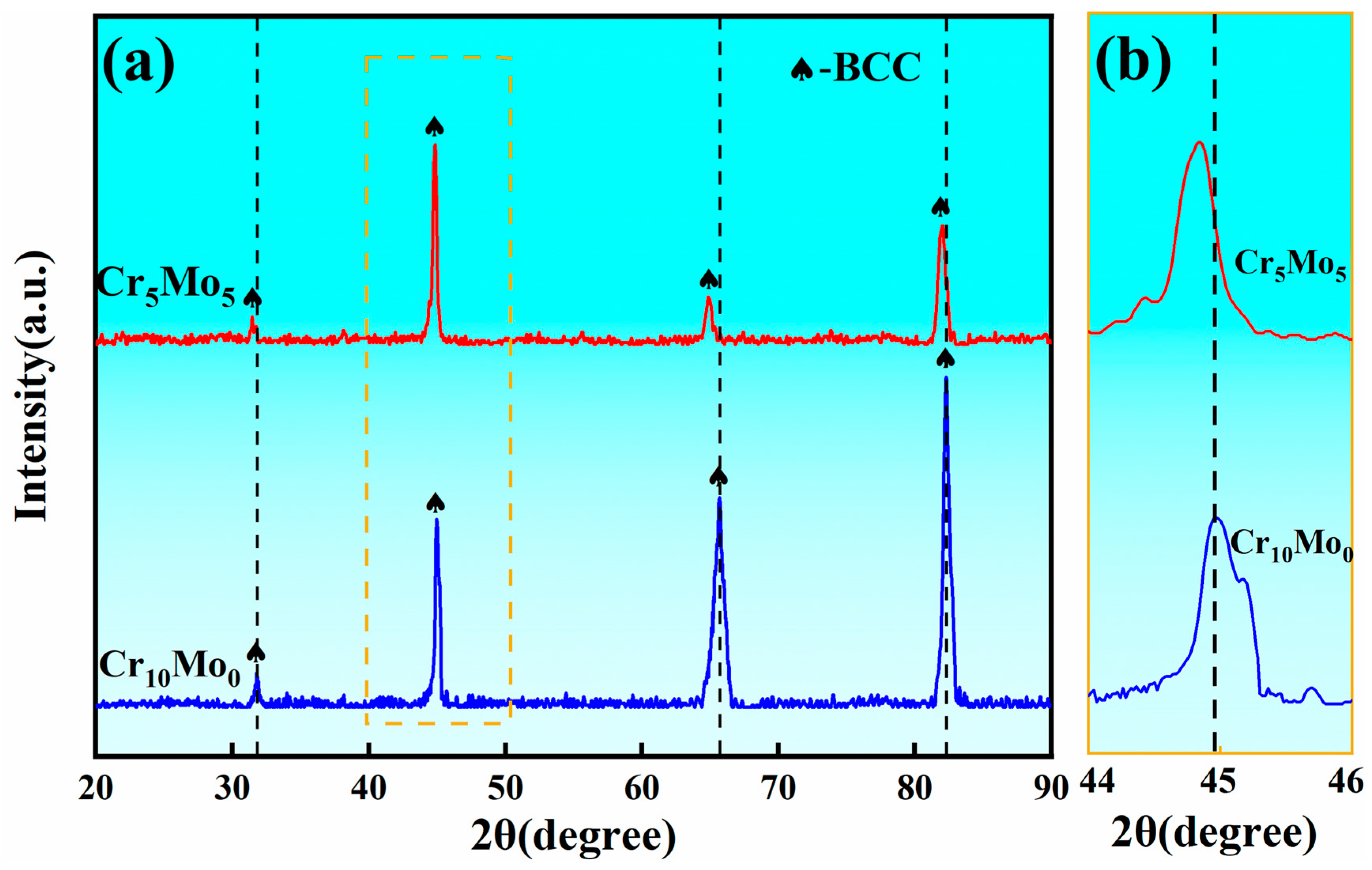
Figure 1 shows the XRD spectrum of the Ni35Al30(FeCo)25Cr10-xMox (x = 0, 5) HEAs. Only the BCC diffraction peak can be identified for both Cr10Mo0 and Cr5Mo5. With the addition of Mo, the peak positions of the four diffraction peaks at Cr5Mo5 all shift to lower angles than the four diffraction peaks at Cr10Mo0. According to the Bragg equation, the position of the diffraction peak is related to the interfacial spacing. The addition of Mo aggravated the lattice distortion of the alloy, and the interfacial spacing increased. Therefore, the θ angle decreased and the position of the diffraction peak shifted to the left.
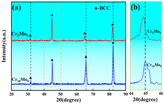
Figure 1.
(a) XRD pattern of Ni35Al30(FeCo)25Cr10-xMox (x = 0, 5) HEAs and (b) partially enlarged view.
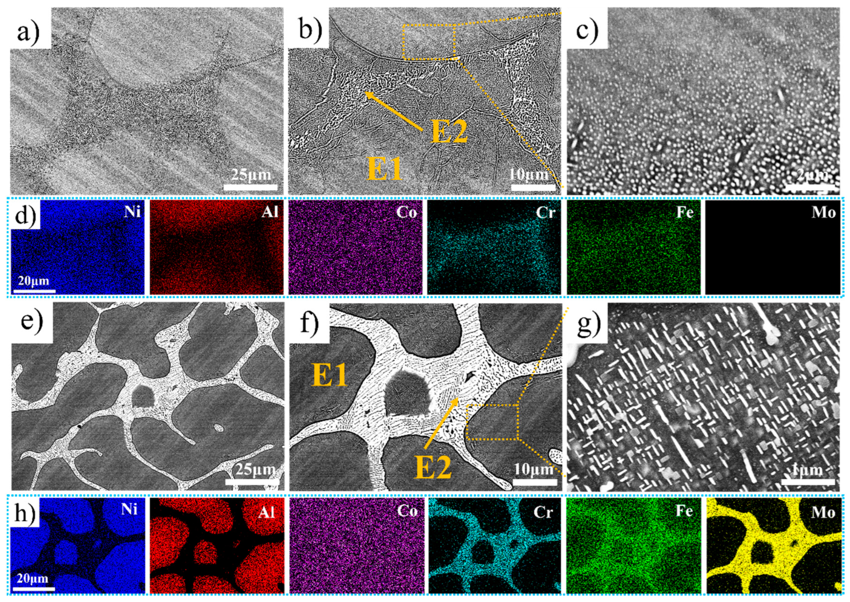
Figure 2 shows the backscattered SEM images and map scanning results of the Ni35Al30(FeCo)25Cr10-xMox (x = 0, 5) HEAs. For convenience of description, the black phase is labeled E1, and the white phase is labeled E2. Spherical nanoprecipitated phases are present in Cr10Mo0 at E1 and close to E2 (as shown in Figure 2b), and the smaller size of the spherical nanoprecipitated phases is closer to E2, the larger the size (as shown in Figure 2c). Cr5Mo5 has a hypoeutectic microstructure. Notably, there are acicular and plate-like nanoprecipitates at E1 and near E2 (as shown in Figure 2g). Figure 2d and Figure 2h show the element distributions in Cr10Mo0 and Cr5Mo5, respectively. Ni and Al are enriched mainly in E1; Co is evenly distributed in E1 and E2; and Cr, Fe, and Mo are enriched mainly in E2. To determine the elemental composition of each phase further, an EDS point scan was performed, and the relevant data are summarized in Table 2. The data in the table are the average values of at least three points. Compared with those of Cr10Mo0, in the E1 phase of Cr5Mo5, the Ni and Al contents increased, and the Cr and Fe contents decreased. Notably, the Mo content varies greatly in E1 and E2, the Mo content segregates in E2, and the Ni and Al contents in E2 are significantly lower than those in Cr10Mo0 in the E2. The addition of Mo inhibits the diffusion of Ni and Al into E2.

Figure 2.
SEM images and elemental distributions of Ni35Al30(FeCo)25Cr10-xMox (x = 0, 5) HEAs (a–d) Cr10Mo0, and (e–h) Cr5Mo5.
Table 2.
Elemental content of phases in Ni35Al30(FeCo)25Cr10-xMox (x = 0, 5) HEAs.
Owing to the existence of many acicular and plate-like precipitates in Cr5Mo5 (as shown in Figure 2g), the two precipitated phases were further identified via TEM. The results are shown in Figure 3. The figure shows the SAED pattern of the matrix phase in Figure 3b, revealing that the matrix of Cr5Mo5 has a BCC structure. The FFT shown in Figure 3e was performed on the HRTEM image at the interface between the matrix and the plate phase, and the results indicate that the plate phase has a BCC crystal structure. Figure 3g shows an HRTEM image of the matrix and acicular phase interface, which also has a BCC (as shown in Figure 3h). The above analyses reveal that only one crystal structure, BCC, is present in the microstructure of Cr5Mo5, which is consistent with the previous XRD results. Notably, only one set of diffraction spots was detected at the interface between the matrix and the acicular phase and the plate phase, indicating that there was a coherent interface between the matrix and the two precipitates [33,34]. Figure 3c, Figure 3f and Figure 3i show IFFT images of the matrix, plate phase, and acicular phase, and the lattice spacings are 0.2045 nm, 0.2094 nm, and 0.291 nm, respectively. Figure 3j shows the EDS surface scan images of the matrix and two precipitates. Combined with the previous results, the plate phase and the acicular phase are both Cr- and Mo-rich BCC phases. Table 3 shows that the Cr and Mo contents of the acicular phase are greater than those of the plate phase.
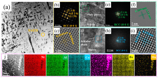
Figure 3.
TEM image, HRTEM image. and EDS surface scan of the Ni35Al30(FeCo)25Cr5Mo5 HEA: (a) bright-field image; (b) SAED image of the matrix; (c) IFFT image of the matrix; (d) HRTEM image of the interface between the matrix and the plate phase; (e) FFT image of the green region; (f) IFFT image of the plate phase; (g) HRTEM image of the interface between the matrix and the acicular phase; (h) FFT image of the blue region; (i) IFFT image of the acicular phase; (j) EDS surface scan.
Table 3.
Elemental content of precipitated phases of the Cr5Mo5.
3.2. Compressive Performance and Friction and Wear Performance of Alloys at Different Temperatures
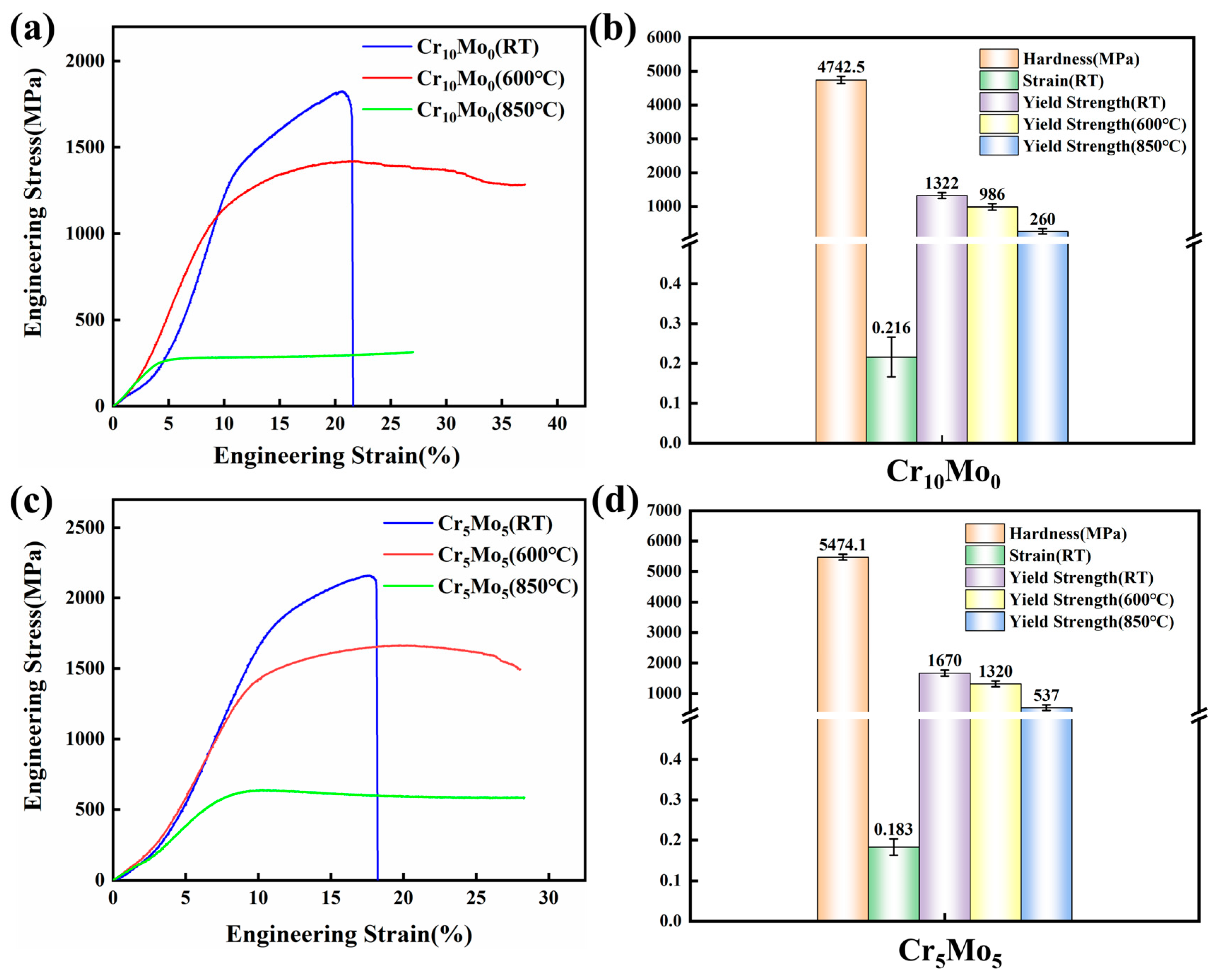
Figure 4a and Figure 4c show the engineering stress–strain curves of Cr10Mo0 and Cr5Mo5 at room temperature, 600 °C, and 800 °C, respectively. The relevant test results are shown in Figure 4b,d. Figure 4 shows that as the temperature increases, the yield strength of the two alloys decreases, whereas the strain increases. When the temperature increased from room temperature to 600 °C, the yield strength of Cr10Mo0 decreased from 1322 MPa to 986 MPa, and the yield strength of Cr5Mo5 decreased from 1670 MPa to 1320 MPa. As the temperature continues to increase to 850 °C, the yield strengths of the Cr10Mo0 and Cr5Mo5 alloys are 260 MPa and 537 MPa, respectively. When the temperature increases from 600 °C to 850 °C, the softening resistance of the two alloys decreases, whereas the plasticity increases. The addition of Mo has a significant effect on the high-temperature mechanical properties of the Ni35Al30(FeCo)25Cr10-xMox (x = 0, 5) alloy system. The Cr5Mo5 alloy exhibited excellent mechanical properties. The matrix and the precipitates were in a coherent relationship (as shown in Figure 3), so Cr5Mo5 had a perfect combination of high strength and ductility at room temperature. Compared with that of the Cr10Mo0 alloy, the yield strength of the Cr5Mo5 alloy increased by 33.87% and 106.5% at 600 °C and 850 °C, respectively. Figure 4b amd Figure 4d show that the average hardness values of Cr10Mo0 and Cr5Mo5 are 4742.5 MPa and 5474.1 MPa, respectively, and the addition of Mo significantly increases the hardness of the alloy. There is a positive correlation between yield strength and hardness [35].
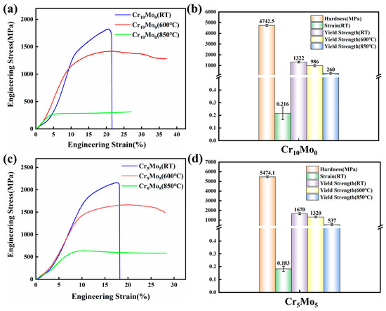
Figure 4.
Mechanical properties of Ni35Al30(FeCo)25Cr10-xMox (x = 0, 5) HEAs at room temperature and high temperature. (a,c) Engineering stress–strain curves and (b,d) corresponding mechanical property parameters.
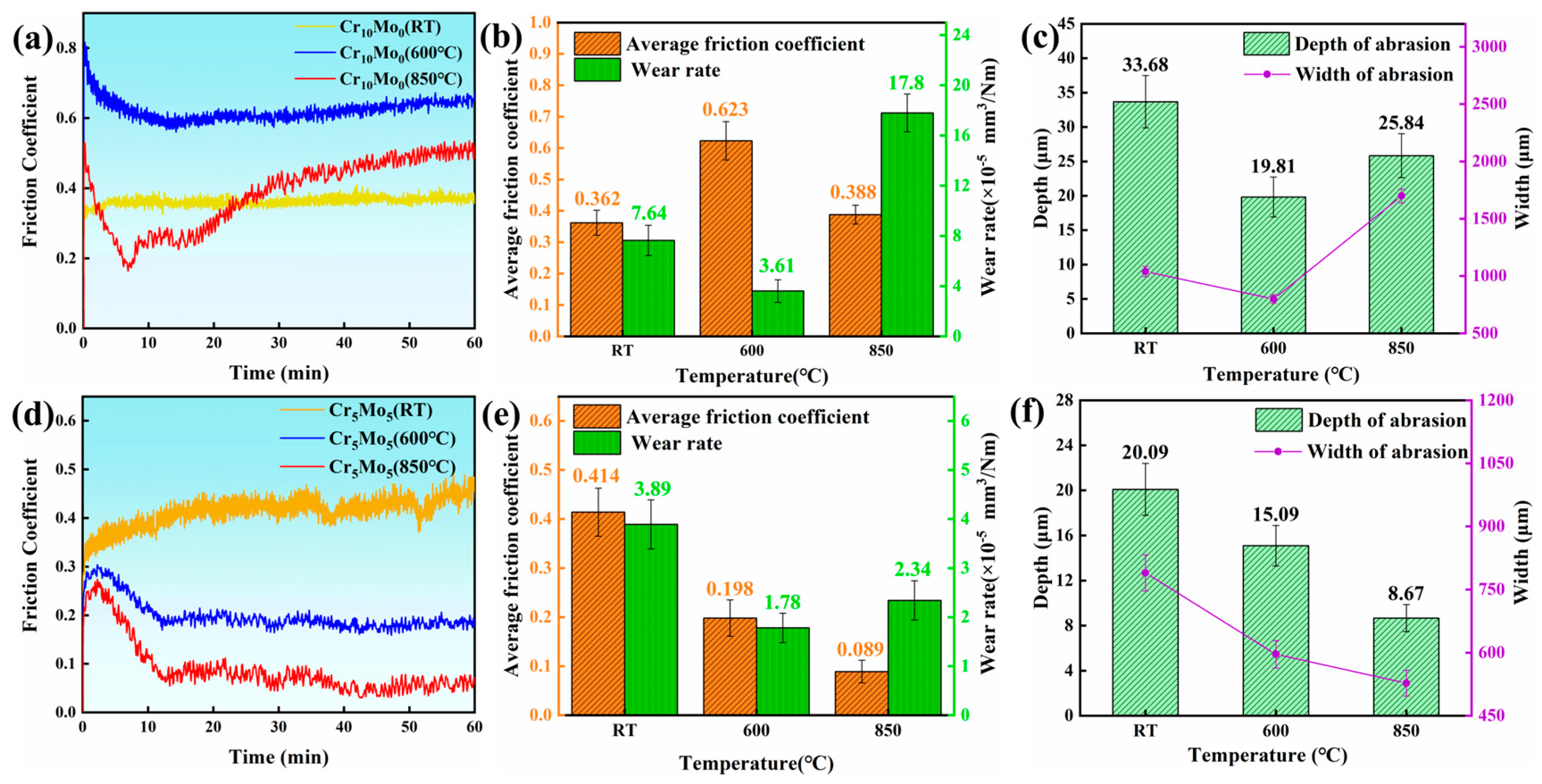
To explore the effect of temperature on the friction and wear performance of Ni35Al30(FeCo)25Cr10-xMox (x = 0, 5) HEAs, the wear morphology of the alloy after the wear test was subjected to SEM and EDS analysis. Figure 5 shows the wear resistance data of the Ni35Al30(FeCo)25Cr10-xMox (x = 0, 5) HEAs. Figure 5a and Figure 5c show the friction coefficient curves of Cr10Mo0 and Cr5Mo5 at different temperatures, respectively. The friction coefficient curve shows that the friction coefficient region curves of the two alloys at all three temperatures have two stages. First, in the running-in stage, owing to the cracking of the worn surfaces and the increase in the contact area between the friction pair and the alloy, the friction coefficient increases rapidly and dramatically [36]. A stable stage occurs when the friction coefficient becomes more stable and fluctuates within a narrow range. The adhesion layer plays an important role in the friction coefficient of a sample and prevents direct contact between the friction pair and the sample surface [37]. On the one hand, a higher temperature reduces the mechanical strength of Cr10Mo0, making it more prone to plastic deformation and increasing the actual contact area between the friction pair and the alloy, thus increasing the friction coefficient [38,39]. On the other hand, the Cr10Mo0 adhesion layer has poor stability at high temperatures and is prone to decomposition and peeling (as shown in Figure 6(a1–c1)). At high temperatures, the exfoliated oxide debris may cause the adhesive to slip, thus improving the friction coefficient. Therefore, as the temperature increased, the friction coefficient of Cr10Mo0 first increased but then decreased. The adhesion layer of Cr5Mo5 is very stable (as shown in Figure 6(d1–f1)) and does not peel off and decompose in a large area at high temperatures. Therefore, the friction coefficient of Cr5Mo5 decreased as the temperature increased. The adhesion layer is explained in detail below. Figure 5b,e show that as the temperature increases, the wear rates of the two alloys both decrease first and then increase. At the same temperature, the wear rate of Cr5Mo5 is lower than that of Cr10Mo0. Figure 5c,f summarize the width and depth of the wear track of the two alloys at different temperatures. Cr10Mo0 has the lowest wear rate at 600 °C, at 3.61 × 10⁻⁵ mm3/Nm. The track depth and width were 19.81 µm and 798.97 µm, respectively. Cr5Mo5 had the lowest wear rate at 600 °C, with a value of 1.78 × 10⁻⁵ mm3/Nm; the depth and width of the wear track were 15.09 µm and 596.2 µm, respectively. In summary, the results show that the addition of Mo significantly improves the wear resistance of NiAl-based HEAs.

Figure 5.
Data used to characterize the wear resistance. (a) Friction coefficient curves of Cr10Mo0 at different temperatures. (b) Wear rate and average friction coefficient of Cr10Mo0 at different temperatures. (c) Depth and width of the wear scars at different temperatures for Cr10Mo0. (d) Friction coefficient curves of Cr5Mo5 at different temperatures. (e) Wear rate and average friction coefficient of Cr5Mo5 at different temperatures. (f) Depth and width of the wear scars at different temperatures for Cr5Mo5.
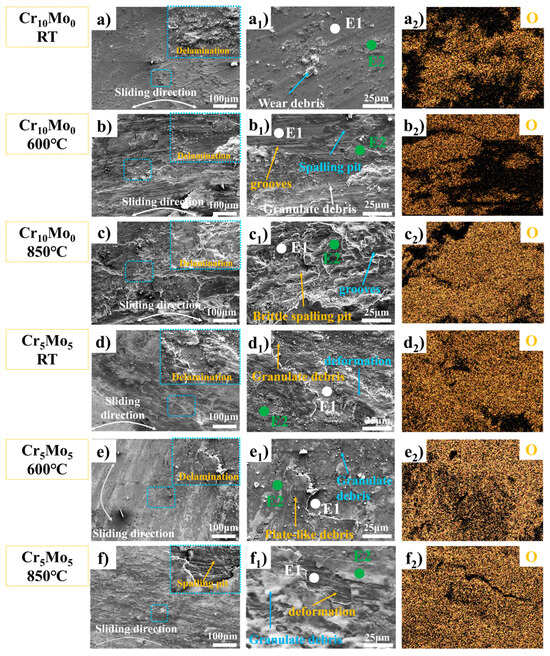
Figure 6.
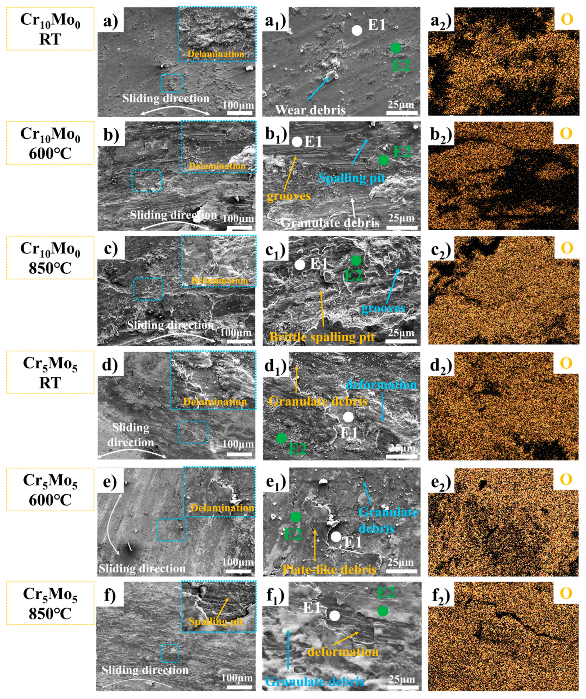
Characterization data of wear traces of Ni35Al30(FeCo)25Cr10-xMox (x = 0, 5) HEAs at different temperatures. SEM images of the worn surface (a–f), local magnification (a2–f2), and EDS energy spectrum analysis of the worn surface.
Figure 6 shows the microstructures of the worn surfaces of Cr10Mo0 and Cr5Mo5 at different temperatures, and the worn surfaces of the two alloys at different temperatures clearly delaminated. With increasing temperature, the stratification phenomenon tended to increase. SEM-EDS (summarized in Table 4) and oxygen (O) element distribution analyses were performed at different locations on the worn surface (as shown in Figure 6(a2–f2)). The results revealed that the oxygen content in the wear debris and bonding layer was much greater than that on the sample surface, indicating that the bonding layer was an oxide. At the same temperature, the compactness of the oxide of Cr5Mo5 is much greater than that of Cr10Mo0. During reciprocating friction between the friction pair and the surface of a sample, an instantaneous high temperature is generated at the contact point. The instantaneous high temperature will cause oxidation and softening of the sample surface and may also cause the wear debris to decompose or fall off [11]. During repeated loading and unloading cycles under the action of friction, these worn debris particles are repeatedly sintered and squeezed and adhere to the sample surface to form a debris layer. The formation of the debris layer is the reason why the alloy friction curve rises sharply after the start of the experiment. On the one hand, the debris layer increases the friction coefficient; on the other hand, it prevents direct contact between the friction pair and the alloy surface, thereby promoting the formation of an adhesion layer and reducing the alloy wear rate.
Table 4.
SEM-EDS point analysis of Ni35Al30(FeCo)25Cr10-xMox (x = 0, 5) HEAs wear traces in different locations.
After the two alloys were subjected to wear tests at room temperature, many grooves, wear particles, and spalling pits were observed on the worn surface (as shown in Figure 6(a1,d1)), indicating that the wear mechanism was mainly abrasion at room temperature. The deepening of the wear grooves on the surface of the wear marks, the distribution of large adhesive layers and the large number of wear particles at 600 °C (as shown in Figure 6(b1)) indicate that the wear mechanism of Cr10Mo0 at 600 °C is abrasive and adhesive wear. At 600 °C, a dark adhesion layer formed on the surface of Cr5Mo5; the adhesion layer increased significantly; a large number of wear particles were also observed; and the number of grooves was significantly lower than that at room temperature (as shown in Figure 6(d1)), indicating that the wear mechanism of Cr10Mo0 at 600 °C is abrasive wear and adhesive wear. At 850 °C, the number of wear particles on the Cr10Mo0 surface decreases significantly, many flaking pits appear, and the surface is very rough. These results indicate that the wear mechanism of Cr10Mo0 at 850 °C is adhesive wear. The same explanation explains the increase in the friction coefficient and wear rate of Cr10Mo0 at 850 °C. At 850 °C, the adhesion layer on the surface of Cr5Mo5 decreased slightly, the size of the wear particles decreased significantly compared with that at 600 °C, the number also decreased sharply, and the worn surface was smoother. These results indicate that the wear mechanism of Cr5Mo5 at 850 °C is adhesive wear. Owing to the combined action of thermal oxidation and friction, the two alloys formed adhesion layers in the wear track at high temperatures. This effectively isolates the friction pair from the sample and protects the underlying material from extra wear. The adhesion layer of Cr10Mo0 is unstable and prone to spalling and decomposition at high temperatures, resulting in an increase in the wear rate of the alloy. The addition of Mo makes the Cr5Mo5 adhesion layer more stable and effectively reduces the wear rate of NiAl-based HEAs at high temperatures.
3.3. Corrosion Performance
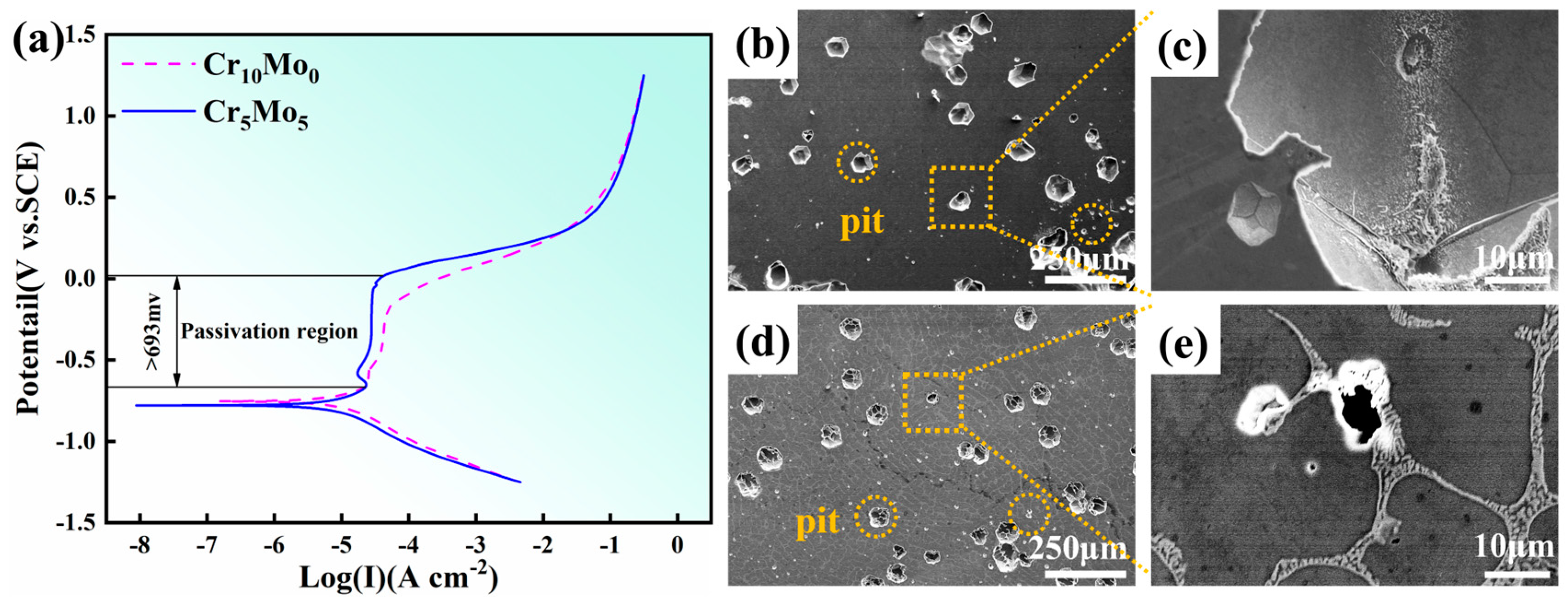
Figure 7a shows the results of the dynamic potential polarization test of the Cr10Mo0 and Cr5Mo5 HEAs after soaking in 3.5 wt% NaCl solution for 2 h. Both samples exhibited very obvious passivation regions. When the width of the passivation interval reaches 693 mV, the polarization curve transitions directly from the Tafel linear region to the passivation region, and no obvious activation–passivation transition process is observed. This phenomenon indicates that a passivation film with a protective effect has been spontaneously formed on the electrode surface at the OCP. The specific parameters of the polarization curve are self-corrosion potential (Ecorr), pitting corrosion potential (Epit), corrosion current density (Icorr) and passivation current density (Ipass), as shown in Table 5. The self-corrosion potential is the potential at which the electrode material corrodes under the OCP, and this parameter reflects the electrochemical stability of the material in a given medium. The self-corrosion potentials of the two alloys are almost the same. The corrosion current density was used to characterize the corrosion process of the alloy electrode during the reaction, and the Icorr of the alloy decreased with increasing Mo content. Therefore, the uniform corrosion resistance of the alloy improved. Epit was used to characterize the ability of alloys to resist localized corrosion and pitting corrosion. Epit increased with increasing Mo content. An increase in the critical point corrosion potential indicates increased resistance of the alloy to local corrosion. Ipass decreases with increasing Mo content, indicating that the passive film on the alloy surface becomes easier to form after the addition of Mo. Figure 7b–e shows the corrosion morphology of the Ni35Al30(FeCo)25Cr10-xMox (x = 0, 5) HEAs after electrochemical testing. The results show that pitting corrosion is the main form of corrosion of the two alloys and that pitting corrosion preferentially occurs at the grain boundaries. The average size of the pits on the surface of the Cr10Mo0 alloy was the largest. With the addition of Mo, the number and size of pits in the Cr5Mo5 alloy decreased.
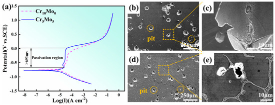
Figure 7.
Corrosion morphologies and potential dynamic polarization curves of Ni35Al30(FeCo)25Cr10-xMox (x = 0, 5) HEAs: (a) potential dynamic polarization curves; (b,c) Cr10Mo0; (d,e) Cr5Mo5.
Table 5.
Fitting parameters of the polarization curves of Ni35Al30(FeCo)25Cr10-xMox (x = 0, 5) HEAs.
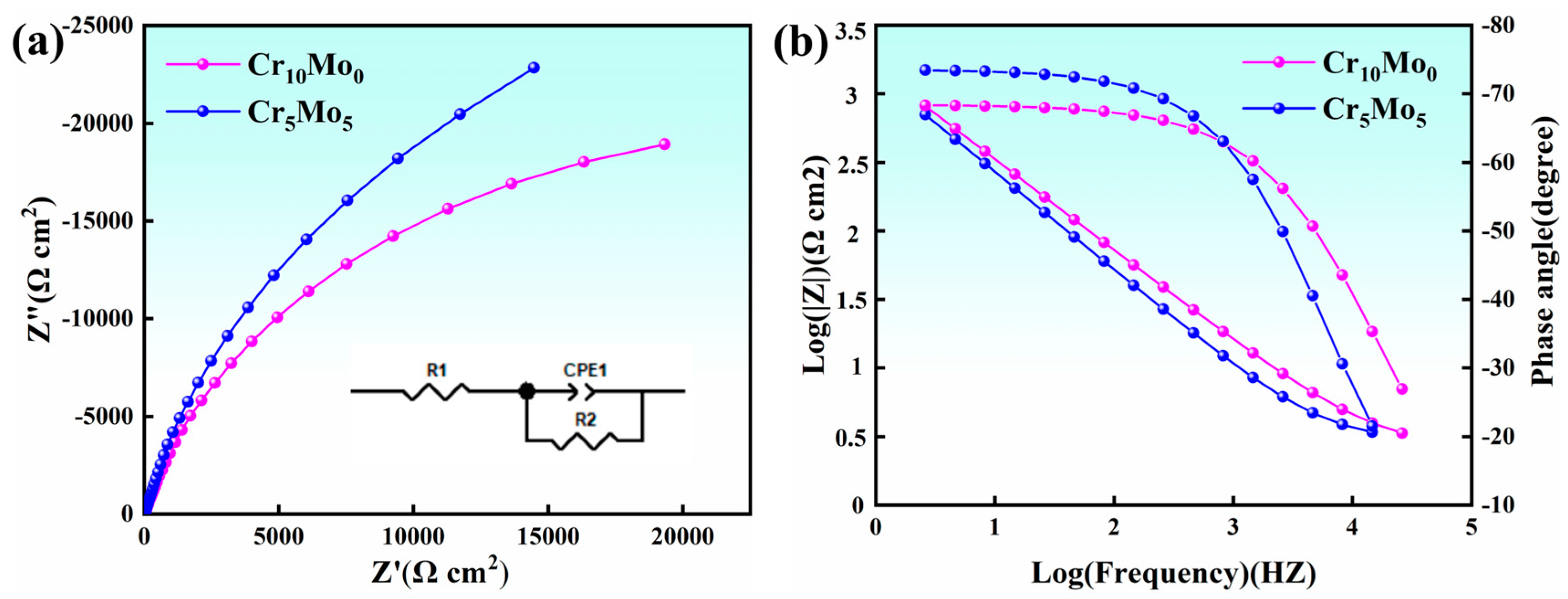
Figure 8 shows the results of electrochemical AC impedance spectroscopy of Ni35Al30(FeCo)25Cr10-xMox (x = 0, 5) HEAs. Figure 8a shows a Nyquist plot. The Nyquist plots of both Cr10Mo0 and Cr5Mo5 showed typical semicircular features, which confirmed the formation of a protective passivation layer on the surface of the materials. From the impedance spectral characteristics, the diameter size of the semicircle is directly related to the protective performance of the passivation film, with a larger diameter representing a higher impedance value of the film layer. The arc radius increased with increasing Mo content, indicating that the impedance of the passivation film continuously increased and that the protection of the passivation film improved. Figure 8b shows the Bode plots of Cr10Mo0 and Cr5Mo5. The curves of the two alloys in the intermediate frequency range (1 Hz–1000 Hz) both showed broadened arcs with phase angles greater than 67°, which is typical of the passivation characteristics of metals. The stability of the passivation film increases when the value of the phase angle increases and remains steady [40,41]. The equivalent circuit model (as shown in Figure 8a Inset) reveals that Rs represents the solution resistance, R2 represents the resistance element of the charge transfer resistance, and CPE1 represents the constant-phase angle element of the passivation film capacitance (which can be used to calculate the characteristics of the passivation film). Owing to the unevenness and deviation of the current distribution caused by the unevenness of the passivation film surface, the actual capacitive characteristics of the passivation film and the theoretical capacitance do not completely match. Therefore, the pure capacitance is replaced by a constant-phase angle element (CPE) [42]. The relevant parameters of the equivalent circuit are shown in Table 6. The fitted curve of the EIS experiment matched the experimental curve very well, indicating that the constructed equivalent circuit model was basically consistent with the actual electrode surface response.
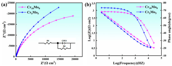
Figure 8.
Electrochemical AC impedance spectra of Ni35Al30(FeCo)25Cr10-xMox (x = 0, 5) HEAs; (a) Nyquist plot and equivalent circuit; (b) bode figure.
Table 6.
Impedance fitting parameters of Ni35Al30(FeCo)25Cr10-xMox (x = 0, 5) HEAs.
4. Conclusions
In this project, Ni35Al30(FeCo)25Cr10-xMox (x = 0, 5) HEAs were developed, and the effects of Mo on the microstructure, mechanical properties, wear performance, and corrosion performance of NiAl-based HEAs were investigated. The addition of Mo changed the morphology of the alloy precipitates from spherical to acicular and plate-like. On the one hand, the addition of Mo results in solid solution strengthening and precipitation strengthening; on the other hand, the precipitates maintain a coherent relationship with the matrix so that the alloy yield strength greatly increases without greatly weakening the plasticity. The addition of Mo greatly improved the stability of the alloy adhesion layer and made it denser. As the temperature increases, the wear mechanism changes from abrasive wear to adhesive wear. At 600 °C, Cr5Mo5 resulted in the lowest wear rate, at 1.78 × 10⁻⁵ mm3/N·m. The addition of Mo improved the performance of the alloy passivation film, increased the impedance of the alloy, reduced the corrosion current density of the alloy, and increased the pitting potential.
Author Contributions
Conceptualization, YS.; Methodology, Z.X.; Validation, A.L.; Resources, A.L.; Data curation, Y.S.; Writing—original draft, Z.X.; Writing—review & editing, X.W.; Supervision, X.W.; Project administration, T.M.; Funding acquisition, TM. All authors have read and agreed to the published version of the manuscript.
Funding
This work was supported by the National Natural Science Foundation of China [Grant number: 52301160].
Institutional Review Board Statement
Not applicable.
Informed Consent Statement
Not applicable.
Data Availability Statement
Data will be made available upon request.
Conflicts of Interest
The authors declare no conflict of interest.
References
- Du, X.H.; Gao, C.; Wu, B.L.; Zhao, Y.H.; Wang, J.J. Enhanced Compression Ductility of Stoichiometric NiAl at Room Temperature by Y and Cu c-Co-addition. Int. J. Miner. Metall. Mater. 2012, 19, 348–353. [Google Scholar] [CrossRef]
- Bochenek, K.; Basista, M. Advances in processing of NiAl intermetallic alloys and composites for high temperature aerospace applications. Prog. Aerosp. Sci. 2015, 79, 136–146. [Google Scholar] [CrossRef]
- Wang, L.; Gao, L.; Shen, J.; Zhang, Y.; Liu, G.; Zhao, P.; Zhang, G. Eutectic Composition Design, Microstructure, and Room Temperature Mechanical Property of NiAl-Cr-Ta Three-Phase Alloy. Metall. Mater. Trans. A 2022, 53, 1479–1485. [Google Scholar] [CrossRef]
- Wang, D.; Ning, H.; Wang, B.; Liu, G.; Yuan, S. Fabrication of a NiAl-Cr(Mo) Eutectic Alloy with Network Microstructure for High-Temperature Strengthening. Mater. Sci. Eng. A 2022, 835, 142628. [Google Scholar] [CrossRef]
- Wang, L.; Yao, C.; Shen, J.; Zhang, Y.; Wang, T.; Xu, H.; Gao, L.; Zhang, G. Microstructures and Compressive Properties of NiAl-Cr (Mo) and NiAl-Cr Eutectic Alloys with Different Fe Contents. Mater. Sci. Eng. A 2019, 744, 93–603. [Google Scholar] [CrossRef]
- Li, Z.; Pradeep, K.G.; Deng, Y.; Raabe, D.; Tasan, C.C. Metastable high-entropy dual-phase alloys overcome the strength-ductility trade-off. Nature 2016, 534, 227–230. [Google Scholar] [CrossRef]
- George, E.P.; Raabe, D.; Ritchie, R.O. High-entropy alloys. Nat. Rev. Mater. 2019, 4, 515–534. [Google Scholar] [CrossRef]
- Miracle, D.B.; Senkov, O.N. A critical review of high entropy alloys and related Concepts. Acta Mater. 2017, 122, 448–511. [Google Scholar] [CrossRef]
- Huo, W.; Zhou, H.; Fang, F.; Zhou, X.; Xie, Z.; Jiang, J. Microstructure and properties of novel CoCrFeNiTax eutectic high-entropy alloys. J. Alloys Compd. 2018, 735, 897–904. [Google Scholar] [CrossRef]
- Chen, B.; Li, Z.B.; Liu, J.R.; Zhang, G.H. Effect of molybdenum addition on microstructure and mechanical properties of 90% tungsten heavy alloys. Int. J. Refract. Met. Hard Mater. 2022, 106, 105868. [Google Scholar] [CrossRef]
- Chuang, M.H.; Tsai, M.H.; Wang, W.-R.; Lin, S.J.; Yeh, J.W. Microstructure and wear behavior of AlxCo1.5CrFeNi1.5Tiy high-entropy alloys. Acta Mater. 2011, 59, 6308–6317. [Google Scholar] [CrossRef]
- Addepalli, S.N.; Joladarashi, S.; Ramesh, M.R. Phase evolution and high-temperature wear behavior of non-equiatomic metastable CoCrNiTiMox HEA coatings fabricated by high-velocity oxy-fuel technique. Mater. Today Commun. 2023, 35, 106310. [Google Scholar] [CrossRef]
- Wang, J.; Zhang, Z.; Dai, H.; Fujiwara, H.; Chen, X.; Ameyama, K. Enhanced corrosion resistance of CoCrFeMnNi high entropy alloy using heterogeneous structure design. Corros. Sci. 2022, 209, 110761. [Google Scholar] [CrossRef]
- Han, F.; Li, C.Y.; Huang, J.Q.; Wang, J.C.; Xia, C.B.; Xue, L.; Wang, C.M. Effect of nitric acid concentration on corrosion behavior of CrFeCoNi high entropy alloy. Mater. Today Commun. 2024, 41, 110779. [Google Scholar] [CrossRef]
- Patnamsetty, M.; Ghosh, S.; Somani, M.C.; Peura, P. Dynamic softening kinetics of Al0.3CoCrFeNi high-entropy alloy during high temperature compression and its correlation with the evolving microstructure and micro-texture. Mater. Charact. 2023, 197, 112693. [Google Scholar] [CrossRef]
- Lu, Y.; Dong, Y.; Guo, S.; Jiang, L.; Kang, H.; Wang, T.; Wen, B.; Wang, Z.; Jie, J.; Cao, Z.; et al. A promising new class of high-temperature alloys: Eutectic high-entropy alloys. Sci. Rep. 2014, 4, 6200. [Google Scholar] [CrossRef]
- Wu, Y.D.; Cai, Y.H.; Chen, X.H.; Wang, T.; Si, J.J.; Wang, L.; Wang, Y.D.; Hui, X.D. Phase composition and solid solution strengthening effect in TiZrNbMoV high-entropy alloys. Mater. Des. 2015, 83, 651–660. [Google Scholar] [CrossRef]
- Zhang, X.; Li, R.; Huang, L.; Amar, A.; Wu, C.; Le, G.; Liu, X.; Guan, D.; Yang, G.; Li, J. Influence of in situ and ex situ precipitations on microstructure and mechanical properties of additive manufacturing CoCrFeMnNi high-entropy alloys. Vacuum 2021, 187, 110111. [Google Scholar] [CrossRef]
- Qin, G.; Chen, R.R.; Zheng, H.T.; Fang, H.Z.; Wang, L.; Su, Y.Q.; Guo, J.J.; Fu, H.Z. Strengthening FCC-CoCrFeMnNi high entropy alloys by Mo addition. J. Mater. Sci. Technol. 2019, 4, 578–583. [Google Scholar] [CrossRef]
- Wu, S.W.; Yang, T.; Cao, B.X.; Luan, J.H.; Jia, Y.F.; Xu, L.; Mu, Y.K.; Zhang, T.L.; Kong, H.J.; Tong, X.; et al. Multicomponent Ni-rich high-entropy alloy toughened with irregular-shaped precipitates and serrated grain boundaries. Scr. Mater. 2021, 204, 114066. [Google Scholar] [CrossRef]
- Liu, W.H.; Lu, Z.P.; He, J.Y.; Luan, J.H.; Wang, Z.J.; Liu, B.; Liu, Y.; Chen, M.W.; Liu, C.T. Ductile CoCrFeNiMox high entropy alloys strengthened by hard intermetallic phases. Acta Mater. 2016, 116, 332–342. [Google Scholar] [CrossRef]
- Zhuang, Y.X.; Zhang, X.L.; Gu, X.Y. Effect of molybdenum on phases microstructure and mechanical properties of Al0.5CoCrFeMoxNi high entropy alloys. J. Alloys Compd. 2018, 743, 514–522. [Google Scholar] [CrossRef]
- Miao, J.W.; Guo, T.M.; Ren, J.F.; Zhang, A.J.; Su, B.; Meng, J.H. Optimization of mechanical and tribological properties of FCC CrCoNi multi-principal element alloy with Mo addition. Vacuum 2018, 149, 324–330. [Google Scholar] [CrossRef]
- Wang, D.C.; Tao, X.P.; Zhang, S.; Wang, X.G.; Wu, C.L.; Zhang, C.H.; Chen, H.T.; Sun, X.F.; Zhou, Y.Z. Dependence of molybdenum content on the cavitation corrosion synergy and wear failure of laser cladded CoCrFeNiMnMo high entropy alloy coatings. Eng. Fail. Anal. 2024, 165, 108824. [Google Scholar] [CrossRef]
- Deng, G.Y.; Tieu, A.K.; Su, L.H.; Wang, P.; Wang, L.; Lan, X.D.; Cui, S.G.; Zhu, H.T. Investigation into reciprocating dry sliding friction and wear properties of bulk CoCrFeNiMo high entropy alloys fabricated by spark plasma sintering and subsequent cold rolling processes: Role of Mo element concentration. Wear 2020, 460–461, 203440. [Google Scholar] [CrossRef]
- Niu, Z.Z.; Wang, Y.Z.; Geng, C.; Xu, J.; Wang, Y. Microstructural evolution, mechanical and corrosion behaviors of as-annealed CoCrFeNiMox (x = 0, 0.2, 0.5, 0.8, 1) high entropy alloys. J. Alloys Compd. 2020, 820, 153273. [Google Scholar] [CrossRef]
- Chou, Y.L.; Yeh, J.W.; Shih, H.C. The effect of molybdenum on the corrosion behaviour of the high-entropy alloys Co1.5CrFeNi1.5Ti0.5Mox in aqueous environments. Corros. Sci. 2010, 52, 2571–2581. [Google Scholar] [CrossRef]
- Hsu, W.C.; Kao, W.P.; Yeh, J.W.; Tsai, C.W. Effect of Mo on the Mechanical and Corrosion Behaviors in Non-Equal Molar AlCrFeMnNi BCC High-Entropy Alloys. Materials 2022, 15, 751. [Google Scholar] [CrossRef]
- Wang, X.F.; Zhang, Y.; Qiao, Y.; Chen, G.L. Novel microstructure and properties of multicomponent CoCrCuFeNiTix alloys. Intermetallics 2007, 15, 357–362. [Google Scholar] [CrossRef]
- Guo, S.; Liu, C.T. Phase stability in high entropy alloys: Formation of solid-solution phase or amorphous phase. Prog. Nat. Sci. Mater. Int. 2011, 21, 433–446. [Google Scholar] [CrossRef]
- Chen, M.; Shi, X.H.; Yang, H.; Liaw, P.K.; Gao, M.C.; Hawk, J.A.; Qiao, J. Wear behavior of Al0.6CoCrFeNi high-entropy alloys: Effect of environments. J. Mater. Res. 2018, 33, 3310–3320. [Google Scholar] [CrossRef]
- Lan, L.W.; Yang, H.J.; Guo, R.P.; Wang, X.J.; Zhang, M.; Liaw, P.K.; Qiao, J.W. High-temperature sliding wear behavior of nitrided Ni45(CoCrFe)40(AlTi)15 high-entropy alloys. Mater. Chem. Phys. 2021, 270, 124800. [Google Scholar] [CrossRef]
- Li, Z.; Zhang, Z.; Liu, X.; Li, H.; Zhang, E.; Bai, G.; Xu, H.; Liu, X.; Zhang, X. Strength, plasticity and coercivity tradeoff in soft magnetic high-entropy alloys by multiple coherent interfaces. Acta Mater. 2023, 254, 118970. [Google Scholar] [CrossRef]
- Wang, L.; Wang, L.; Zhou, S.; Xiao, Q.; Xiao, Y.; Wang, X.; Cao, T.; Ren, Y.; Liang, Y.J.; Wang, L.; et al. Precipitation and micromechanical behavior of the coherent ordered nanoprecipitation strengthened Al-Cr-Fe-Ni-V high entropy alloy. Acta Mater. 2021, 216, 117121. [Google Scholar] [CrossRef]
- Chen, Z.X.; Ding, H.S.; Chen, R.R.; Guo, J.J.; Fu, H.Z. An innovation for microstructural modification and mechanical improvement of TiAl alloy via electric current application. Sci. Rep. 2019, 9, 5518. [Google Scholar] [CrossRef]
- Nguyen, C.; Tieu, A.K.; Deng, G.; Wexler, D.; Vo, T.D.; Wang, L.; Yang, J. Tribological performance of a cost-effective CrFeNiAl0.3Ti0.3 high entropy alloy based self-lubricating composite in a wide temperature range. Tribol. Int. 2022, 174, 107743. [Google Scholar] [CrossRef]
- Xiao, J.K.; Tan, H.; Wu, Y.Q.; Chen, J.; Zhang, C. Microstructure and wear behavior of FeCoNiCrMn high entropy alloy coating deposited by plasma spraying. Surf. Coat. Technol. 2020, 385, 125430. [Google Scholar] [CrossRef]
- Deng, G.; Dong, B.; Zhang, C.; Wang, R.; Yang, Z.; Nie, N.; Wang, P.; Wang, L.; Wang, H.; Tian, Y.; et al. Microstructure, microhardness and high-temperature tribological properties of CoCrFeNiMnTi0.3 high entropy alloy coating manufactured by powder-bed arc additive manufacturing. Surf. Coat. Technol. 2024, 485, 130918. [Google Scholar] [CrossRef]
- Liang, X.M.; Xing, Y.Z.; Li, L.T.; Yuan, W.K.; Wang, G.F. An experimental study on the relation between friction force and real contact area. Sci. Rep. 2021, 11, 20366. [Google Scholar] [CrossRef]
- Zhang, M.; Shi, X.; Li, Z.; Xu, H.; Li, G. Corrosion behaviors and mechanism of CrFeNi2 based high-entropy alloys. Corros. Sci. 2022, 207, 110562. [Google Scholar] [CrossRef]
- Gu, X.H.; Li, X.R.; Zhang, Q.H.; Wu, L.K.; Cao, F.H. Passive film and surface characterization of Alx(CoCrFeNi)100-x (x = 0, 5, 10, 15, 20) high entropy alloys. Intermetallics 2023, 162, 107994. [Google Scholar] [CrossRef]
- Wang, Y.; Jin, J.S.; Zhang, M.; Wang, X.Y.; Gong, P.; Zhang, J.C.; Liu, J.C. Effect of the grain size on the corrosion behavior of CoCrFeMnNi HEAs in a 0.5 M H2SO4 solution. J. Alloys Compd. 2021, 858, 157712. [Google Scholar] [CrossRef]

Disclaimer/Publisher’s Note: The statements, opinions and data contained in all publications are solely those of the individual author(s) and contributor(s) and not of MDPI and/or the editor(s). MDPI and/or the editor(s) disclaim responsibility for any injury to people or property resulting from any ideas, methods, instructions or products referred to in the content. |
© 2025 by the authors. Licensee MDPI, Basel, Switzerland. This article is an open access article distributed under the terms and conditions of the Creative Commons Attribution (CC BY) license (https://creativecommons.org/licenses/by/4.0/).