Article

Microstructure and Properties of Al-Cr-N Ternary Wear-Resistant Coatings on Cr12MoV Alloy Tool Steel by Multiarc Ion Plating

1
College of Marine Equipment and Mechanical Engineering, Jimei University, Xiamen 361021, China
2
College of Turbine Engineering, Jimei University, Xiamen 361021, China
*
Author to whom correspondence should be addressed.
Coatings 2025, 15(4), 487; https://doi.org/10.3390/coatings15040487
Submission received: 28 February 2025 / Revised: 16 April 2025 / Accepted: 17 April 2025 / Published: 19 April 2025

Abstract

:
Al-Cr-N ternary coatings were deposited on the surface of Cr12MoV alloy tool steel via multiarc ion plating technology. The microstructure and mechanical and tribological properties of these coatings were systematically characterized, analyzed, and compared with those of the uncoated substrate specimens. The results indicated that under optimal conditions, Al70Cr30 alloy was effectively ionized, leading to the formation of AlN and CrN phases between Al ions, Cr ions, and nitrogen atoms. These phases were uniformly distributed within the coating, forming an ordered lattice structure. At a bias voltage of −60 V, the deposited Al-Cr-N coating exhibited a uniform and smooth morphology. However, because of the inherent characteristics of arc deposition, droplets and craters were observed on the coating surface as a result of sputtering and back-sputtering effects. The average nanohardness of the Al-Cr-N ternary coating reached 23.8 ± 3.1 GPa, while the coefficient of friction stabilized at approximately 0.7 during the wear process, compared with around 0.8 for the uncoated Cr12MoV substrate. Compared with the uncoated Cr12MoV substrate, the Al-Cr-N coating demonstrated significantly enhanced hardness and wear resistance, thereby effectively improving the performance of Cr12MoV alloy tool steel.

1. Introduction

Cr12MoV is a high-carbon, chromium-rich alloy tool steel that contains Cr, Mo, and V. These alloying elements endow Cr12MoV with superior properties, including high hardness, excellent wear resistance, and notable corrosion resistance. After quenching and tempering heat treatment, the hardness of Cr12MoV typically reaches 60-62 HRC. Consequently, Cr12MoV is extensively utilized in the production of tools and molds, particularly those with large cross-sections and complex shapes. Under heavy workloads, these tools and molds are often subjected to significant impact, extrusion, and external friction, leading to potential failure modes such as wear and fatigue. Therefore, enhancing the mechanical properties and wear resistance of Cr12MoV alloy steel to extend its service life has become a focal point of current research [1,2].
With the increasing demands on material performance driven by modern manufacturing technology, traditional heat treatment processes have become inadequate. Advanced surface modification techniques, such as physical vapor deposition (PVD), laser surface treatment, and laser cladding, have been widely adopted to improve material surface properties [3,4,5,6]. PVD is a thin-film deposition technology where solid materials are vaporized using heating, ion bombardment, or glow discharge in a vacuum environment. The resulting atoms, ions, or molecules are deposited on the target substrate to form functional coatings with special characteristics, such as high wear resistance, corrosion resistance, and oxidation resistance [6,7,8]. Depositing hard coatings on Cr12MoV alloy steel via PVD technology is an effective approach to enhance its mechanical and wear-resistance properties.
Elements such as Cr and Ti, known for their high melting points and passivation properties in corrosive environments, are commonly used to improve the wear and corrosion resistance of various alloy steels. Their combination with nitrogen forms hard TiN and CrN coatings with NaCl-type structures. These coatings have gained widespread application in advanced machining and high-temperature environments due to their excellent mechanical and tribological properties and chemical stability [6,9]. Extensive research has been conducted on enhancing the properties of TiN and CrN coatings [10,11,12].
Despite their excellent properties, CrN and TiN do not always fully meet industrial requirements. Studies have shown that multicomponent or multilayer coatings, formed by adding new metallic or nonmetallic elements to binary or ternary nitrides, can further enhance coating performance [13,14,15,16]. For instance, Lei Shan et al. [17] added Si to CrN coatings, significantly reducing the friction coefficient and wear rate compared with CrN coatings, thereby improving wear and corrosion resistance. Jihui Chen et al. [18] prepared multilayer CrAlTiN coatings using multiarc ion plating, achieving a friction coefficient of 0.4 at −300 V bias voltage and nano-hardness of 26 GPa. M. Danek et al. [19] investigated TiAlCrN multilayer films and found that increasing Cr content greatly enhanced oxidation resistance.
Many metal elements, especially Al, Ti, Cr, Nb, and W, with similar atomic radii, readily form body-centered cubic (BCC) crystal structures when combined with nitrogen, resulting in nitride coatings, such as Al-Cr-N, with high bonding strength to the substrate, high hardness, and excellent wear resistance [20,21]. In addition to the influence of deposited elements, the properties of the coating are also significantly influenced by its compositional ratio. Despite numerous reports on Al-Cr-N coatings, many studies have overlooked the impact of specific compositional ratios on the microstructure and properties of the coating. In this study, an Al-Cr-N ternary PVD coating with an Al/Cr atomic ratio of 70/30 was deposited on a Cr12MoV alloy steel substrate via multiarc ion plating technology. The microstructural characteristics, mechanical properties, and wear behavior of the Al-Cr-N coating were systematically investigated. This research provides a theoretical foundation for elucidating the intrinsic relationship between coating composition and performance. It also offers guidance for coating compositional design to improve Cr12MoV alloy steel performance.

2. Experimental Processes

2.1. Material and Experimental Preparation

The monolayer Al70Cr30N coating was deposited onto a Cr12MoV alloy tool steel substrate using physical vapor deposition (PVD) technology. The primary chemical composition of the Cr12MoV alloy tool steel is presented in Table 1. The specimens were fabricated into square flakes measuring 20 mm × 20 mm × 5 mm. Prior to the deposition of the AlCrN film, the substrates underwent quenching at temperatures ranging from 1050 to 1100 °C, followed by two tempering processes at temperatures between 510 and 520 °C, resulting in a hardness of 62 HRC. After heat treatment, the surfaces of the specimens were ground and polished with sandpaper, then ultrasonically cleaned in a mixture of ethanol and acetone to eliminate impurities and oxides from the surfaces of the Cr12MoV substrates, ensuring that they remained flat and clean. A round block of cast Al70Cr30 alloy with a purity level exceeding 99.9% was selected as the target material for deposition. In this experiment, the target material Al70Cr30 was produced by casting. Pure aluminum (purity ≥ 99.9%) and chromium (purity ≥ 99.9%) were mixed in an atomic ratio of 70:30 and melted in a vacuum induction furnace with argon gas as the protective atmosphere to avoid metal oxidation. During the melting process, the metal aluminum was heated to a temperature of about 750 °C until it was completely dissolved, and then fine-grained chromium was gradually added and heated gradually to 1500~1600 °C to ensure the complete dissolution of the chromium. Then the liquid alloy was poured into a metal mold preheated to about 260 °C, followed by fast cooling to obtain the target casting.

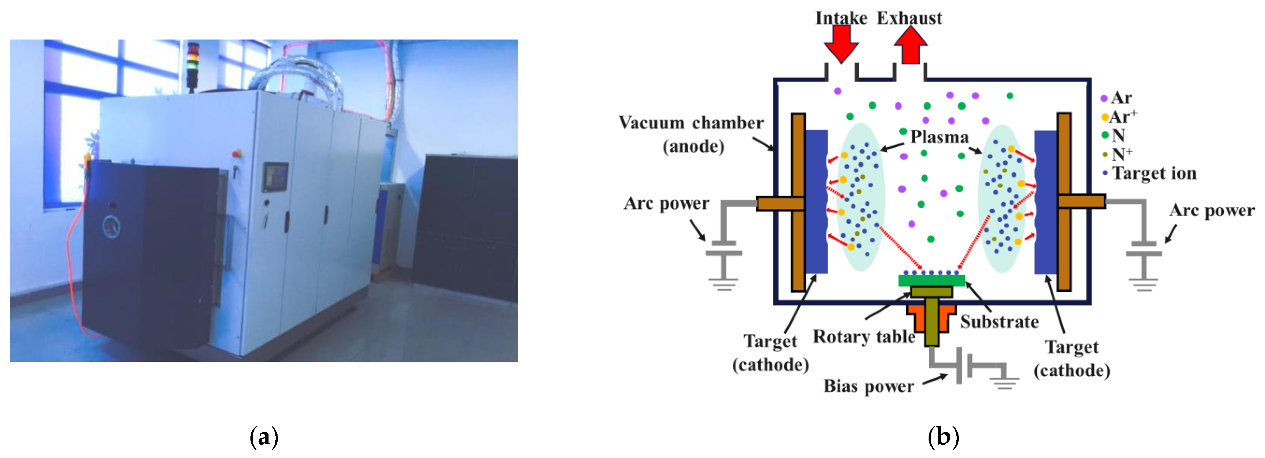
2.2. Coating Preparation Method

AlCrN coatings were fabricated using a physical vapor deposition (PVD) system (ICS-S800, Italy) through a multiarc ion coating process. To ensure uniform application of the coating material onto the substrate, the specimens were securely mounted on a rotary table and placed within a vacuum chamber; the Al70Cr30 alloy target was connected to the cathode, while the Cr12MoV substrate specimen was linked to the anode. The deposition equipment and a schematic representation of the process are illustrated in Figure 1.
The primary process parameters for the preparation of Al-Cr-N coatings were established following a series of preliminary experiments. The specific deposition processes and key parameters were as follows: (1) Ion etching of the substrate. The furnace chamber was evacuated to a vacuum level of 0.5 Pa, with a bias voltage set at −600 V and the substrate preheated to 150 °C. Subsequently, argon gas was introduced into the chamber at a flow rate of 200 mL/min and a pressure of 0.5 Pa. This was followed by ionization of argon under glow discharge conditions, during which Ar+ plasma etched the substrate to eliminate surface oxides. (2) Deposition of AlCrN coating. Argon gas was turned off, and nitrogen was introduced (with a nitrogen flow rate of 150 mL/min and gas pressure ranging from 0.5 to 3 Pa). The bias voltage was maintained at −60 V, with current levels between 50 A and 100 A, while the deposition temperature reached up to 420 °C. The temperature of the circulating cooling water was kept at approximately 13 °C.

2.3. Coating Performance Evaluation

2.3.1. Microstructural Characterization

The surface morphology and cross-sectional microstructure of the AlCrN coating were examined using a scanning electron microscope (SEM, Phenom-XL). The phase composition was analyzed via X-ray diffraction (XRD) with Cu-Kα radiation (wavelength ≈ 0.154 nm). The XRD measurements were conducted over a 2θ range from 0° to 90°, with a step size of 0.5° and a scan rate of 3° per minute.

2.3.2. Tribological Testing

The friction and wear behavior of the coatings and substrates under dry sliding conditions at room temperature (20 °C) was assessed using a tribometer (HT-600, Kaihua, Lanzhou, China). The test parameters included: a SiC ball with a diameter of 4 mm as the counterface material, a motor speed of 300 rpm, an applied load of 8 N, and a test duration of 1800 s. The friction test adopted the ball-on-plate method, in which the sample was mounted on a rotary driven plate. The friction rotation radius was 4 mm. To ensure the reliability of the results, multiple tests were conducted at different locations, and the average values were reported.

2.3.3. Mechanical Property Assessment

Hardness measurements were performed using a nanoindentation tester (NHT2, Anton Paar, Anton Paar, Graz, Austria). Considering the relatively thin thickness of the coating, the maximum indentation depth was controlled to approximately 10–15% of the coating thickness to minimize the influence of the substrate. The maximum load applied was 20 mN, with a holding time 10 s. Tests were conducted at least 3 times at different locations to ensure the accuracy and reliability of the data. Adhesion strength was evaluated through scratch testing using a scratch tester (WS-2005, Kaihua, Lanzhou, China). The scratch test parameters were a load range of 0–90 N, a loading rate of 45 N/min, a scratch length of 10 mm, and a scratch velocity of 5 mm/min. Postscratch failure analysis of the coating’s surface morphology was conducted using an optical microscope (Crossbeam 550, Zeiss, Oberkohen, Germany).

3. Results and Discussion

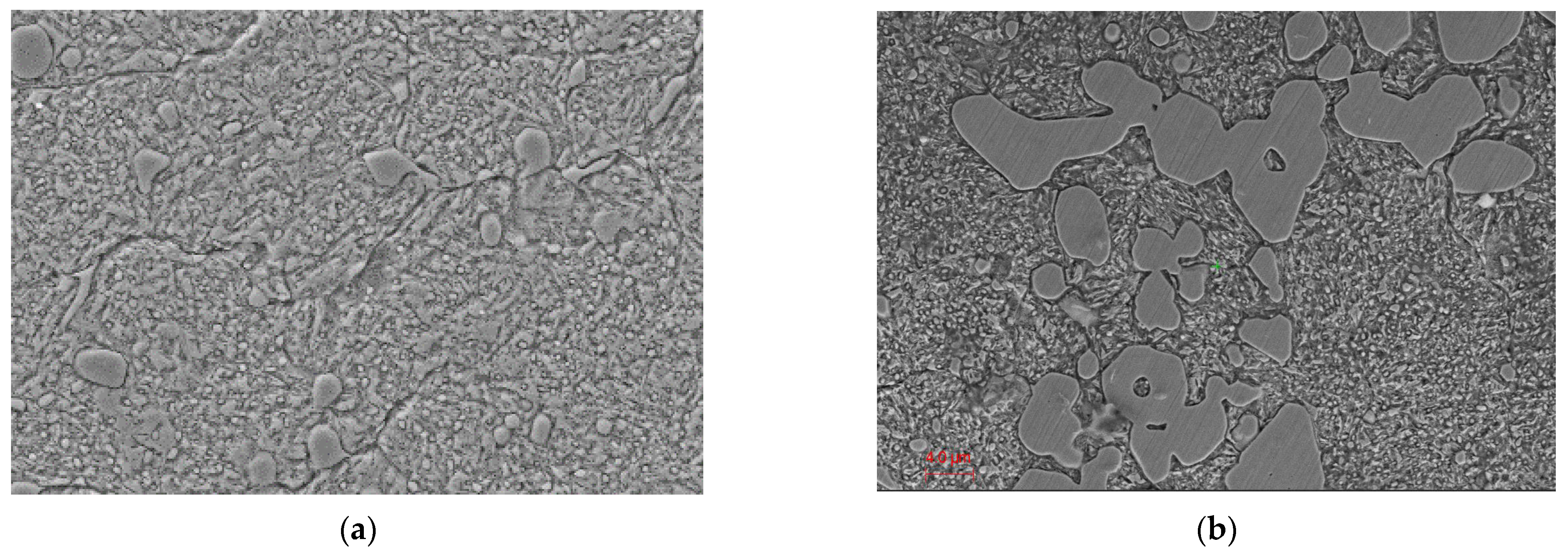
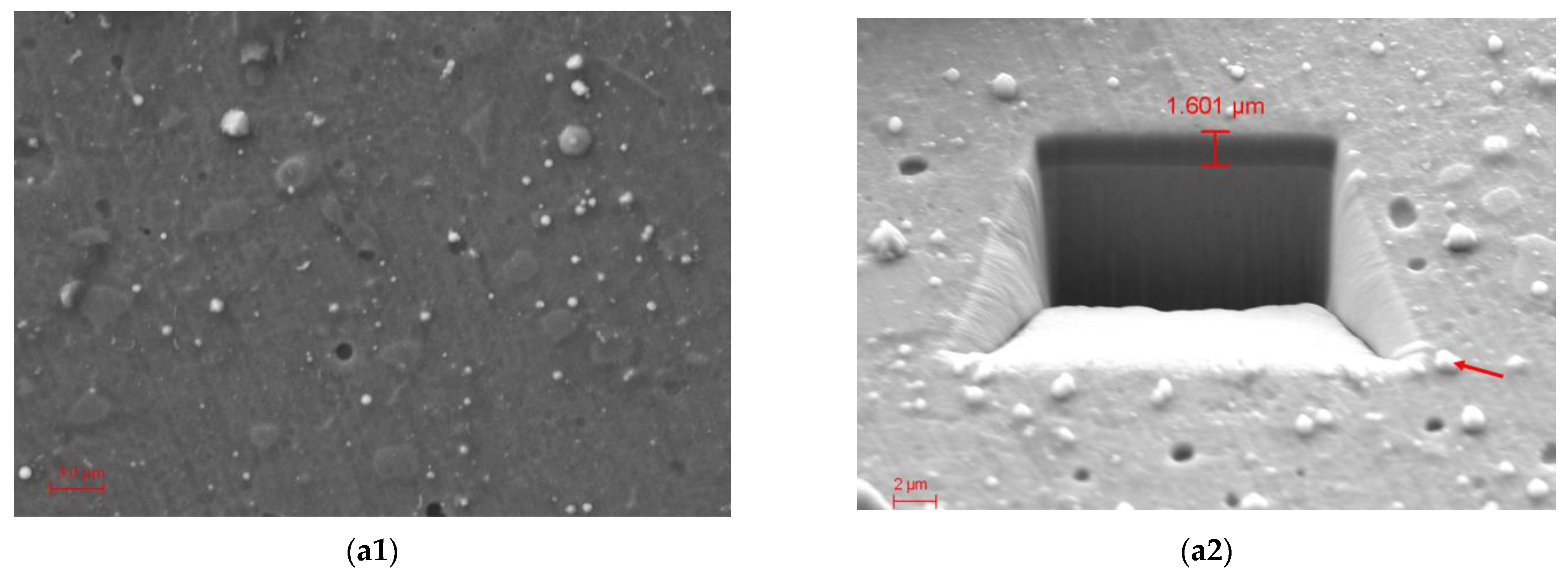
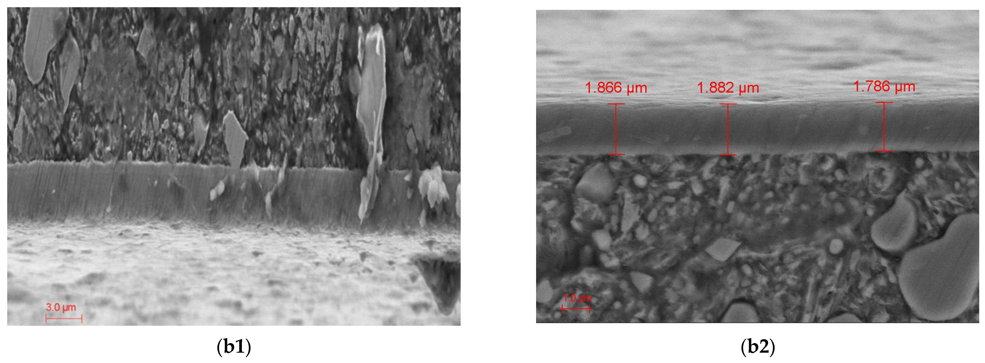
3.1. Coating Microstructure

Figure 2 and Figure 3 present the scanning electron microscopy (SEM) morphology of the uncoated Cr12MoV specimen and the AlCrN coated specimens, respectively. From the microstructure morphology of Cr12MoV in Figure 2, there were some white, massive eutectic carbides unevenly distributed within the tempered martensite matrix, and some granular secondary carbides were also found. The surface of the AlCrN coating on the specimen exhibited a relatively uniform and flat appearance, with no significant defects such as large pinholes, bubbles, or spalling. However, some small deposition particles of varying sizes were noted, along with a limited number of near-circular pits that were randomly and unevenly distributed across the coating surface, as characterized in Figure 3(a1,a2). These defect features (particle deposits and pits) can be primarily attributed to the principles underlying the multiarc ion plating process. Under arc current conditions, localized overheating of the target material occurs, resulting in a molten pool formation on its surface. Subsequently, melt droplets from this target are deposited onto the substrate during sputtering processes, leading to granular deposition. Additionally, collisions among atoms or ions during sputtering may result in aggregation into larger particles before reaching the coating surface; this phenomenon is typically correlated with arc current magnitude [22,23]. As bias voltage increases, droplet size decreases, and the microstructure becomes more uniform [18]. The formation of near-circular pits is attributed to antisputtering effects on the coating surface caused by ion bombardment during physical vapor deposition (PVD).
The morphology of a cross-sectioned coating is illustrated in Figure 3(b1,b2), where optical microscopy was employed to measure coating thickness. As shown in Figure 3(b2), the AlCrN coating was dense and uniform, with approximately uniform thickness. The interface between the coating and substrate was flat while exhibiting dense columnar structures along the thickness direction. Grain growth appeared directed upward and outward as well along the energetically favorable orientation, which led to a strong crystal texture of the material during physical deposition [22].

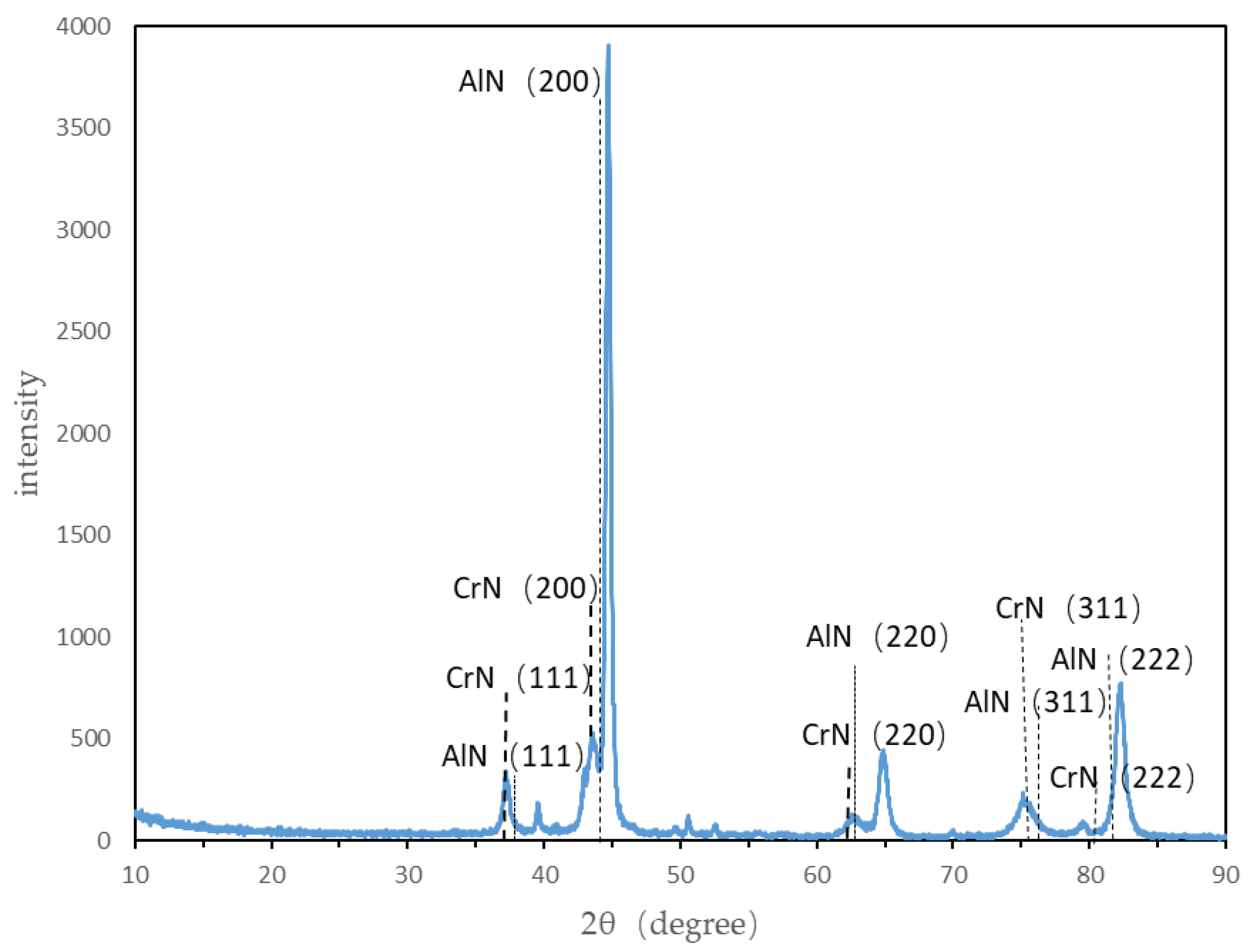
3.2. Physical Phase Composition

The X-ray diffraction (XRD) pattern of the AlCrN coating is presented in Figure 4. As illustrated in the figure, the Al70Cr30N coating primarily consisted of CrN and AlN hard phases, along with a matrix phase. The observed diffraction peaks corresponded to the (111), (200), (220), and (311) crystal planes of these phases and were consistent with those reported for AlCrN PVD coatings in the literature [22,24]. The presence of multiple crystal planes associated with both CrN and AlN phases indicates that the coating exhibited good crystallization. Notably, the intensity of the diffraction peaks was highest at the (200) crystal plane, suggesting that this particular plane had a significant degree of crystallization. Furthermore, this peak’s prominence implies some preferential orientation within the coating at this crystallographic plane. In comparison with A50Cr50N and Al60Cr40N coatings [22], the positions of diffraction peaks in the XRD pattern for Al70Cr30N shifted towards higher angles on the right side as well as increasing in width. This shift suggests that variations in aluminum content influenced the proportions of both the CrN and AlN phases as well as the grain size.

3.3. Coating Hardness

Figure 5 illustrates load–displacement curves obtained from nanoindentation tests conducted on uncoated Cr12MoV specimens and those coated with AlCrN. The average maximum nanoindentation depth recorded for the AlCrN coating was 238.5 nm under a load of 20 mN, while for uncoated Cr12MoV specimens it was measured at 214 nm under a load of 10 mN. When subjected to equivalent loads, it is evident that both average residual indentation depths after unloading were significantly smaller for coated specimens than for their uncoated counterparts. Specifically, when comparing identical loading conditions, indentations made on AlCrN-coated specimens exhibited shallower depths than those on uncoated Cr12MoV samples; moreover, postunloading residual indentation depths were markedly reduced relative to those seen in base materials like Cr12MoV. Based on the load–displacement curve, the nanohardness of the material was then determined by the Oliver–Pharr method [25]. A schematic illustration of the results is shown in Figure 6. In this method, the unloading curves are usually well approximated by the following power law relation:
P = α h h f m
where α and m are power law fitting constants, h f is the permanent depth of penetration after the indenter is fully unloaded, and the amount of sink-in of the indenter   h s is given by:
h s = ϵ P m a x S
where   P m a x is the maximum load; ϵ is a constant that depends on the geometry of the indenter, about 0.72 (for a conical punch), 0.75 (for a paraboloid of revolution), and 1.00 (for a flat punch); the contact stiffness, S , is defined as the slope of the upper portion of the unloading curve during the initial stages of unloading; and the contact depth that the indented with the tested material, h c , is
h c = h m a x h s       = h m a x ϵ P m a x S
A is the contact area that the indented with the tested material, which is a function of h c , described as follows:
A = F h c A = C 0 h c 2 + C 1 h c + C 2 h c 1 2 + C 3 h c 1 4 + C 4 h c 1 8 + C 5 h c 1 16
where C n (n = 0,1,2…) are constants determined by curve-fitting procedures [25].
Once A is determined, the indention hardness can be estimated by:
H = P m a x A  
According to the model and computational method above, the average nanohardness of the single-layer AlCrN coating was found to be 23.8 ± 3.1 GPa, which was consistent with the reported nanohardness values for AlCrN-based coatings in the literature [21] (approximately 22 GPa) but differed from the value of 36 ± 1.2 GPa in the literature [26] because of different Al/Cr composition. In contrast, the average nanohardness of the Cr12MoV substrate was measured at 11.97 GPa.

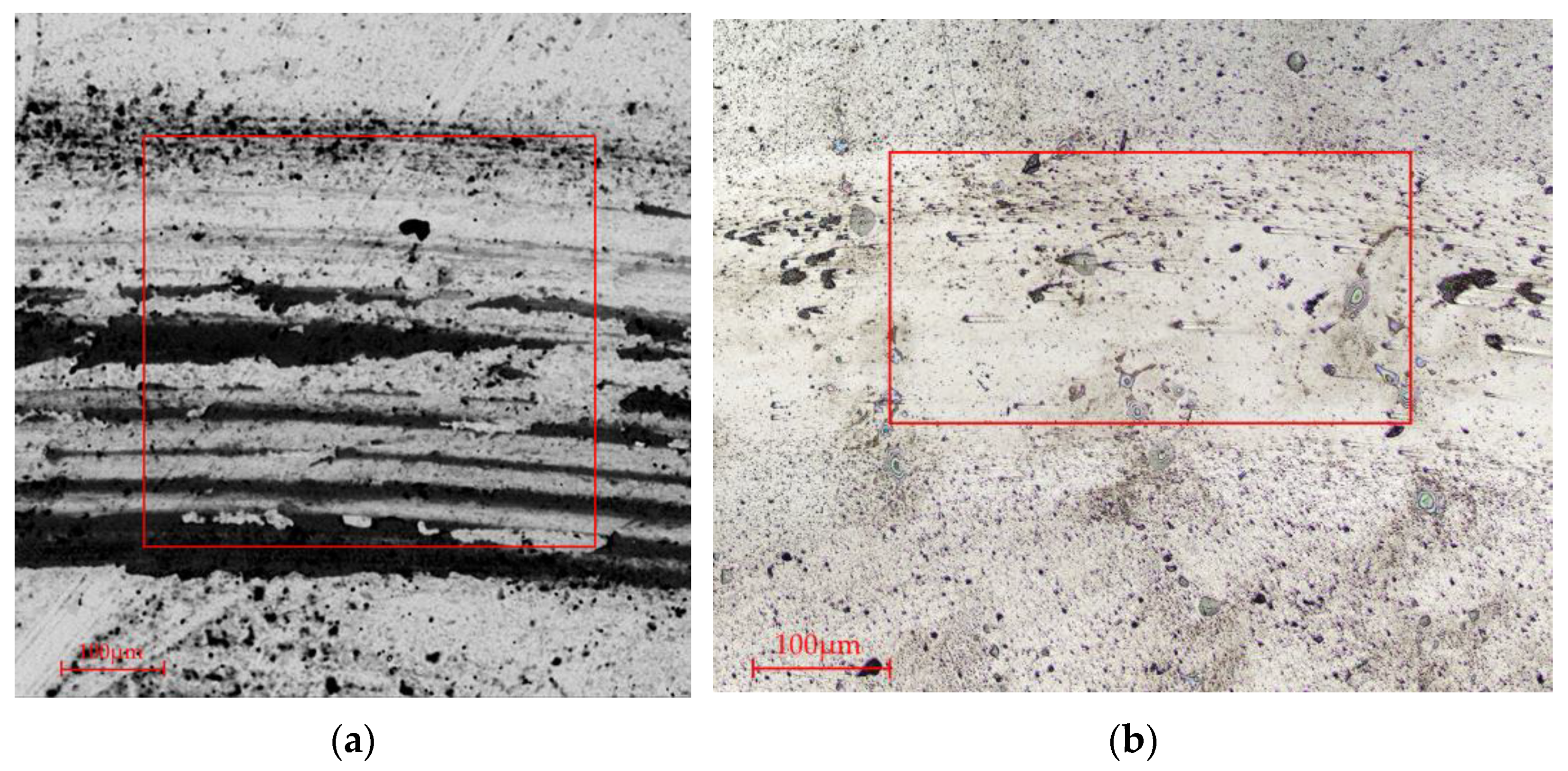
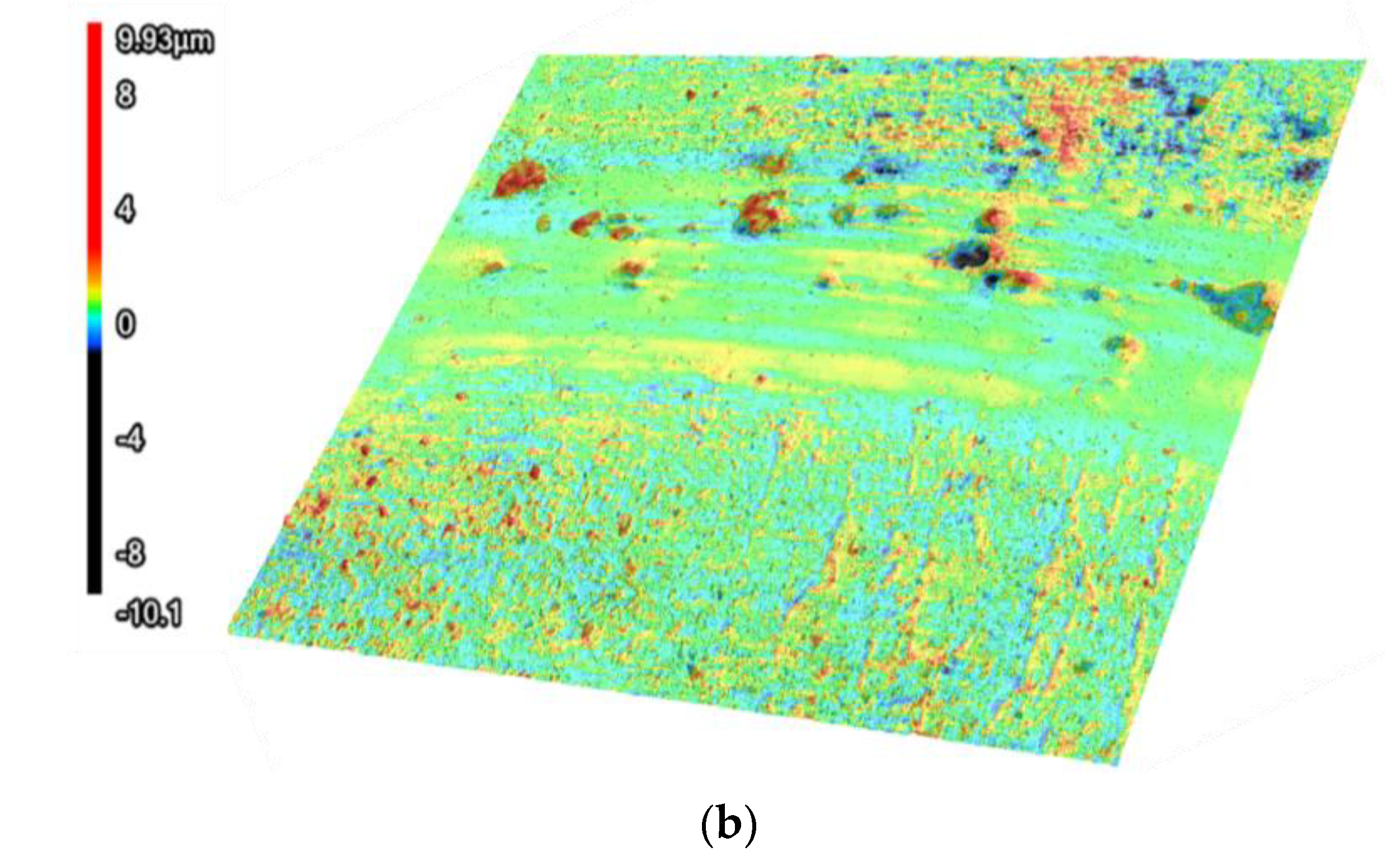
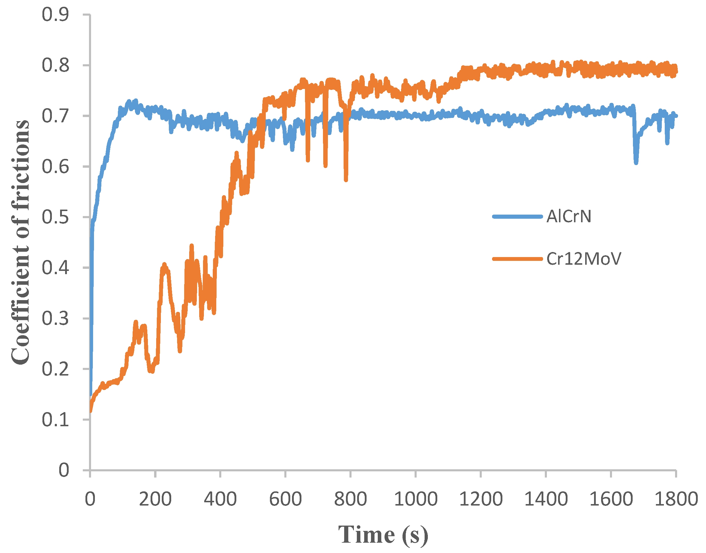
3.4. Wear Performance

Observing the wear track morphologies depicted in Figure 7, the surface of the uncoated Cr12MoV substrate exhibited pronounced gully wear marks caused by friction, with wider and deeper dimensions (Figure 7a). In contrast, the wear marks on the coated AlCrN sample were less prominent and exhibited narrower wear traces (Figure 7b). As shown in the 3D surface profiles of the samples after the wear test in Figure 8, it is evident that the surface of the coated sample remained relatively flat, with an average surface roughness of 0.26 μm. Conversely, the average surface roughness of the uncoated Cr12MoV substrate was measured at 0.81 μm.
In order to evaluate the tribological properties and analyze the tribological behavior of AlCrN coatings, this study obtained the coefficient of friction (COF) curves for both the substrate and coatings through friction and wear experiments, as illustrated in Figure 9. As shown in the figure, the friction process for both the uncoated substrate specimen and the coated specimen can be divided into an initial grinding period followed by a stabilization period of wear. During the initial stage of wear, the coating’s coefficient of friction exhibited a rapid increase from 0 to 100 s, reaching a value of 0.7. This was followed by a further increase between 100 and 150 s, peaking at a maximum value of 0.72 before experiencing a slight decrease; thereafter, fluctuations in COF were significant during the interval from 150 to 800 s, after which it stabilized around approximately 0.7. In [27], AlCrN coating exhibited a similar friction coefficient of 0.65. Similarly, during the first phase (0–150 s), there was an upward trend observed in the friction coefficient for the uncoated Cr12MoV substrate as well; during subsequent testing from 150 to 800 s, its COF values fluctuated but generally trended upwards, reaching about 0.75 before slightly decreasing again to maintain relative stability with values around approximately 0.8 during its stabilization period. The disparity between the coefficients of friction for coated specimens versus those for substrates was attributed to their conditions prior to conducting friction wear experiments. The uncoated Cr12MoV specimen underwent polishing that resulted in an exceptionally smooth surface; consequently, upon initiation of abrasion testing, this surface deteriorated rapidly, leading to substantial fluctuations in COF during early wear stages. In contrast, since no polishing was performed on AlCrN-coated specimens—coupled with sedimentary particles present on their surfaces—the initial wear experienced was significantly intense, resulting in a swift rise in COF within a short timeframe. At stable wear stages following these events, only minor changes were noted regarding fluctuations.
According to the energy spectrum analysis of the wear marks in Region A, as shown in Figure 10, the presence of oxygen and iron elements was detected, indicating that the coating was subject to both oxidative wear and abrasive wear. The detection of carbon (C) and silicon (Si) elements suggests the occurrence of adhesive wear. Additionally, the high content of aluminum (Al) and chromium (Cr) played a significant role in enhancing the wear resistance of the coating.

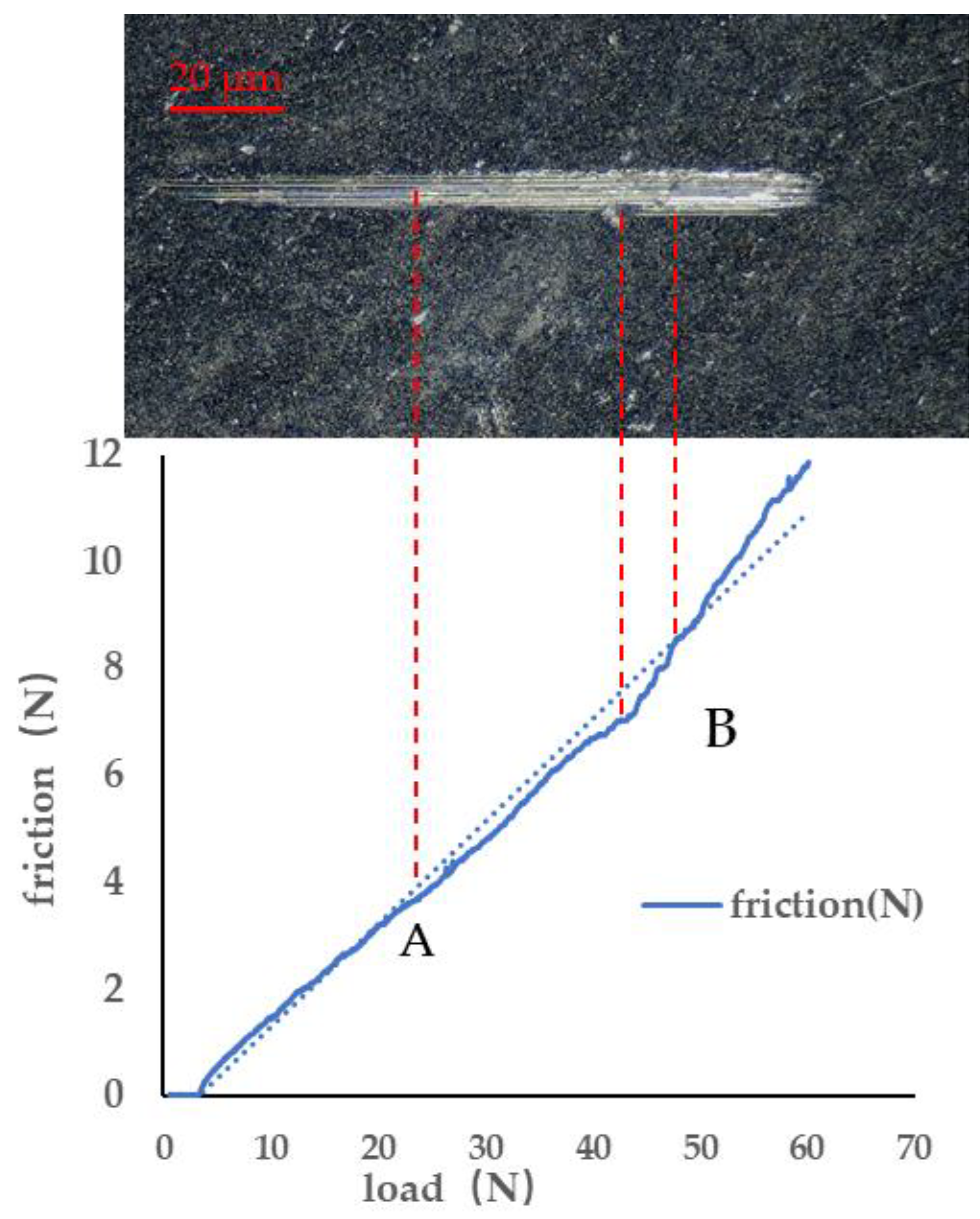
3.5. Coating Bonding Strength

The coating adhesion was evaluated and analyzed based on the dimensions of the scratches, including length, width, and depth, as well as the extent of coating delamination and cracking. The film–substrate adhesion was characterized by a critical load at which there was a sudden change in the friction force. Figure 11 and Figure 12 show the load–friction force curves of the AlCrN-coated specimens tested during the scratch experiments and the surface morphology after the scratch tests, respectively. As illustrated in Figure 12, as the probe indenter made contact with the film coating and moved forward, friction developed on the coating’s surface. Along the scratch path, the friction force increased with the applied load, while the scratch width and depth also progressively increased. Significant flaking occurred on both sides of the scratch until the coating eventually failed. Combined with the scratch morphology and the friction–load curve, it can be observed that at point A (as shown in Figure 11), cracking initiated at the scratch edge, indicating the onset of coating failure; at point B, the coating started to peel off, signifying complete failure. At this stage, the load reached the critical value, and the adhesion strength of the coating was about 48 N. The adhesion strength of the coating to the substrate was reported in [24] to be around 15 N when coated with different Al/(Al + Cr) ratios of 0.66, 0.47, and 0.46. In contrast, the adhesion strength of Al50Cr50 and Al60Cr40 coatings to SDSS steel substrate was reported in [22] to be approximately 90 N. This indicates that the adhesion strength between AlCrN coatings and the substrate is significantly influenced by both the characteristics of the substrate material and the deposition process used.
The process of coating failure caused by force was divided into four stages: (1) Elastic deformation of the coating occurred under positive load and friction. Although the coefficient of friction was small at this point, the frictional force increased linearly with increasing load. (2) The load continued to increase, and the frictional force increased at the same time. When the combined force exceeded the elastic limit of the coating, the coating was plastically deformed, the scratches continued to deepen, the slope of the friction curve became larger, the coefficient of friction continued to increase, and the friction curve appeared at the inflection point when the tip of the indenter needle scratched through the coating and contacted the substrate. (3) Load continued to increase, and the depth of the scratch continued to increase along with it. At this time, a large area of peeling appeared in the coating, the scratch width was significantly wider, the friction and plastic deformation suddenly increased, the friction curve fluctuated, and finally, the coating broke. (4) Friction occurred between the indenter and the substrate because the coating was completely broken and the indenter tip was in direct contact with the substrate. Scratches produced by the indenter on the substrate continued to deepen with increasing load. The friction curve lay above the linear fit line because of the higher coefficient of friction of the substrate.

4. Conclusions

In this study, Al-Cr-N ternary coatings were deposited on Cr12MoV alloy die steel via multiarc ion plating technology. The morphology and microstructure of the coatings were characterized by SEM and XRD, while their mechanical and tribological properties were evaluated through abrasion tests, nanoindentation tests, and scratch tests. The key findings are summarized as follows:
1. At a bias voltage of −60 V, the surface morphology of the Al70Cr30N coating on the Cr12MoV substrate exhibited relative uniformity and smoothness. However, because of phenomena inherent to the process of arc deposition, droplet formation and craters from back-sputtering were observed on the coating surface.
2. The Al70Cr30N coating primarily consisted of CrN and AlN hard cubic phases with well-defined crystallinity. These phases were present at the (111), (200), (220), and (311) crystal planes, with the highest diffraction intensity at the (200) plane, indicating preferential orientation along this plane. The aluminum content influenced the positions and widths of the diffraction peaks for CrN and AlN phases in the XRD patterns, suggesting that it affects the phase composition and grain size within the coating.
3. The average nanohardness of the single-layer Al70Cr30N ternary coating was 23.8 ± 3.1 GPa, compared with 11.97 GPa for the Cr12MoV substrate. Additionally, the friction coefficient of the Al-Cr-N coating stabilized at approximately 0.7, which was lower than the 0.8 observed for the Cr12MoV base material. Consequently, the AlCrN coating demonstrated superior hardness and wear resistance, and during the wear process, the coating experienced abrasive wear, adhesive wear, and oxidation wear. The adhesion test also demonstrated good coating adhesion to the substrate, so Al70Cr30N coating can significantly enhance the wear resistance of Cr12MoV alloy tool steel.

Author Contributions

Conceptualization, S.L.; methodology, R.L.; formal analysis, S.L.; investigation, Y.Z. and Q.H.; resources, R.L.; data curation, Q.H.; writing—original draft preparation, Y.Z.; writing—review and editing, Y.Z. All authors have read and agreed to the published version of the manuscript.

Funding

This research was funded by the Department of Education of Fujian Province of China (grant No. JAT210253).

Institutional Review Board Statement

Not applicable.

Informed Consent Statement

Not applicable.

Data Availability Statement

Data are contained within the article.

Conflicts of Interest

The authors declare no conflict of interest.

References

  1. Bao, C.; Yang, Y.; Xu, C. The wear analysis and life prediction of Cr12MoV alloy steel hammer dies during the radial forging process. CIRP J. Manuf. Sci. Technol. 2025, 57, 63–77. [Google Scholar] [CrossRef]
  2. Wang, R.; Song, Z.F.; Wei, D.Q.; Li, X.K.; Song, J.J.; Mo, Z.Z.; Weng, Y.T.; Yang, F.T. Unveiling the effect of electron beam shock on the microstructure and wear resistance of Cr12MoV steel. VACUUM 2024, 226, 113347. [Google Scholar] [CrossRef]
  3. Liu, Z.; Wang, C.; Mi, G.; Zhang, W.; Wang, J. Surface morphological evolution and microhardness change of Cr12MoV steel by pulsed laser polishing. Opt. Laser Technol. 2024, 171, 110419. [Google Scholar] [CrossRef]
  4. Wang, X.; Zhang, Z.; Men, Y.; Li, X.; Liang, Y.; Ren, L. Fabrication of nano-TiC functional gradient wear-resistant composite coating on 40Cr gear steel using laser cladding under starved lubrication conditions. Opt. Laser Technol. 2020, 126, 106136. [Google Scholar] [CrossRef]
  5. Shi, Y.; Li, Y.; Liu, J.; Yuan, Z. Investigation on the parameter optimization and performance of laser cladding a gradient composite coating by a mixed powder of Co50 and Ni/WC on 20CrMnTi low carbon alloy steel. Opt. Laser Technol. 2018, 99, 256–270. [Google Scholar] [CrossRef]
  6. Dobrzanski, L.A.; Polok, M.; Adamiak, M. Structure and properties of wear resistance PVD coatings deposited onto X37CrMoV5-1 type hot work steel. Mater. Process. Technol. 2005, 164–165, 843–849. [Google Scholar] [CrossRef]
  7. Vengesa, Y.; Fattah-alhosseini, A.; Elmkhah, H.; Imantalab, O.; Keshavarz, M.K. Investigation of corrosion and tribological characteristics of annealed CrN/CrAlN coatings deposited by CAE-PVD. Ceram. Int. 2023, 49, 3016–3029. [Google Scholar] [CrossRef]
  8. Fereshteh-Saniee, N.; Elmkhah, H.; Nouri, M.; Meghdari, M. An investigating of how mechanical properties impact the erosion resistance of CrN, CrTiN, and CrTiSiN PVD coatings. Results Surf. Interfaces 2025, 18, 100422. [Google Scholar] [CrossRef]
  9. Ezugwu, E.O.; Okeke, C.I. Tool life and wear mechanisms of TiN coated tools in an intermittent cutting operation. J. Mater. Process. Technol. 2001, 116, 10–15. [Google Scholar] [CrossRef]
  10. Chiadikobi, C.I.; Thornton, R.; Statharas, D.; Weston, D.P. The effects of deep cryogenic treatment on PVD-TiN coated AISI M2 high speed steel. Surf. Coat. Technol. 2024, 493, 131248. [Google Scholar] [CrossRef]
  11. Xi, Y.; Bai, Y.; Gao, K.; Pang, X.; Yang, H.; Yan, L.; Alex, A. Volinsky. Residual stress and microstructure effects on mechanical, tribological and electrical properties of TiN coatings on 304 stainless steel. Ceram. Int. 2018, 44, 15851–15858. [Google Scholar] [CrossRef]
  12. Liu, L.; Shao, L.; Li, W.; Shang, L.; Zhang, C.; Song, Q. Improving the tribological behavior of CrN film by PVD/HVOF design. Surf. Coat. Technol. 2023, 475, 130171. [Google Scholar] [CrossRef]
  13. Edis, R.; Sinmazcelik, T.; Erturk, A.T. Measuring applied force and energy consumption in deep drawing die Sets: An experimental and numerical analysis of CrN and CrTiN PVD coating effects. Measurement 2024, 224, 113841. [Google Scholar] [CrossRef]
  14. Xu, X.; Sun, J.; Xu, Z.; Li, Z.; Su, F. Microstructure, electrochemical and tribocorrosion behaviors of CrCN nanocomposite coating with various carbon content. Surf. Coat. Technol. 2021, 411, 126997. [Google Scholar] [CrossRef]
  15. Pei, F.; Liu, H.J.; Chen, L.; Xu, Y.X.; Du, Y. Improved properties of TiAlN coating by combined Si-addition and multilayer architecture. J. Alloys. Compd. 2019, 790, 909–916. [Google Scholar] [CrossRef]
  16. Alhafian, M.R.; Valle, N.; Chemin, J.B.; Bourgeois, L.; Penoy, M.; Useldinger, R.; Ghanbaja, J.; Mücklich, F.; Choquet, P. Choquet. Influence of Si addition on the phase structure and oxidation behavior of PVD AlTiN and AlTiCrN coatings using high-resolution characterization techniques. J. Alloys Compd. 2023, 968, 171800. [Google Scholar] [CrossRef]
  17. Shan, L.; Zhang, Y.-r.; Wang, Y.-x.; Li, J.-l.; Jiang, X.; Chen, J.-m. Corrosion and wear behaviors of PVD CrN and CrSiN coatings in seawater. Trans. Nonferrous Met. Soc. China 2016, 26, 175–184. [Google Scholar] [CrossRef]
  18. Chen, J.; Guo, Q.; Li, J.; Yang, Z.; Guo, Y.; Yang, W.; Xu, D.; Yang, B. Microstructure and tribological properties of CrAlTiN coating deposited via multi-arc ion plating. Mater. Today Commun. 2022, 30, 103136. [Google Scholar] [CrossRef]
  19. Danek, M.; Fernandes, F.; Cavaleiro, A.; Polcar, T. Influence of Cr additions on the structure and oxidation resistance of multilayered TiAlCrN films. Surf. Coat. Technol. 2017, 313, 158–167. [Google Scholar] [CrossRef]
  20. Ramírez-Reyna, F.O.; Rodríguez-Castro, G.A.; Figueroa-López, U.; Morón, R.C.; Arzate-Vázquez, I.; Meneses-Amador, A. Effect of nitriding pretreatment on adhesion and tribological properties of AlCrN coating. Mater. Lett. 2021, 284, 128931. [Google Scholar] [CrossRef]
  21. Li, X.; Meng, C.; Xu, X.; He, X.; Wang, C. Effect of Al content on high-temperature oxidation behavior and failure mechanism of CrAl-coated Zircaloy. Corros. Sci. 2021, 192, 109856. [Google Scholar] [CrossRef]
  22. He, Q.; DePaiva, J.M.; Martins, M.M.; Amorim, F.L.; Torres, R.D.; Arif, A.F.; Veldhuis, S.C. PVD coating strategies: Developing a combination of AlCrN and AlTiSiN for enhanced surface performance during threading of super duplex stainless steel. Int. J. Refract. Met. Hard Mater. 2024, 121, 106670. [Google Scholar] [CrossRef]
  23. Fan, Q.; Zhang, S.; Ma, D.; Wu, Z.; Cao, F.; Liu, Y.; Wang, T. Bias voltage optimization and cutting performance of AlCrN coatings deposited by a hybrid technology. Vacuum 2022, 204, 111348. [Google Scholar] [CrossRef]
  24. Neto, N.D.C.; Kloenne, Z.T.; Korenyi-Both, A.L.; Midson, S.P.; Kaufman, M.J. Influence of Al/(Al+Cr) ratio and doping effects on wear and molten aluminum attack resistance in AlCrN-based PVD coatings for lube-free aluminum die casting. J. Mater. Res. Technol. 2022, 20, 1057–1078. [Google Scholar] [CrossRef]
  25. Oliver, W.C.; Pharr, G.M. Measurement of hardness and elastic modulus by instrumented indentation: Advances in understanding and refinements to methodology. J. Mater. Res. 2004, 19, 3–20. [Google Scholar] [CrossRef]
  26. Beake, B.D.; Roberts, J.; Zhu, Y.; Liskiewicz, T.W. Simulating erosion tests with statistically distributed micro-scale impact: A study on PVD TiAlN and AlCrN coatings. Wear 2025, 205911. [Google Scholar] [CrossRef]
  27. Geng, D.; Li, H.; Chen, Z.; Xu, Y.X.; Wang, Q. Microstructure, oxidation behavior and tribological properties of AlCrN/Cu coatings deposited by a hybrid PVD technique. J. Mater. Sci. Technol. 2022, 100, 150–160. [Google Scholar] [CrossRef]
Figure 1. Schematic diagram of PVD coating process. (a) PVD deposition system; (b) schematic of multiarc ion coating process.
Coatings 15 00487 g001
Figure 2. Surface morphology of a Cr12MoV matrix specimen. (a) is the overall surface morphology; (b) is the magnified morphology.
Coatings 15 00487 g002
Figure 3. SEM morphology of AlCrN coated specimen. (a1) Surface morphology of AlCrN coating; (a2) coating morphology with a cut incision, which was made by tilting the table and cutting with an ion beam (Crossbeam 550, Germany); (b1,b2) cross-sectional micrographs of the coating.
Coatings 15 00487 g003aCoatings 15 00487 g003b
Figure 4. XRD pattern of AlCrN coating.
Coatings 15 00487 g004
Figure 5. Load–displacement graph for nanoindentation test.
Coatings 15 00487 g005
Figure 6. Schematic illustration of indentation P–h graph and correlation of parameters [25].
Coatings 15 00487 g006
Figure 7. SEM morphology of wear tracks of samples. (a) Cr12MoV substrate without coating; (b) with AlCrN coating (The morphology of the wear tracks is presented within the red rectangular box).
Coatings 15 00487 g007
Figure 8. Three-dimensional surface profiles of wear tracks. (a) Cr12MoV substrate without coating (Ra 0.81 μm); (b) with AlCrN coating (Ra 0.26 μm).
Coatings 15 00487 g008aCoatings 15 00487 g008b
Figure 9. Coefficient of friction curve between coating and substrate.
Coatings 15 00487 g009
Figure 10. Composition analysis of AlCrN coating in a highlighted wear region.
Coatings 15 00487 g010
Figure 11. Load–friction curves tested along the scratch path during the scratching experiments.
Coatings 15 00487 g011
Figure 12. Surface morphology of coating scratches. (a) Scratch surface morphology; (b) localized magnified view of the rectangular area shown in (a).
Coatings 15 00487 g012
Table 1. Main chemical composition of Cr12MoV alloy steel (w.t%).
ElementCSiMnCrMoV
Percentage of mass1.45~1.70≤0.40≤0.4011.0~12.5.00.40~0.600.15~0.30
Disclaimer/Publisher’s Note: The statements, opinions and data contained in all publications are solely those of the individual author(s) and contributor(s) and not of MDPI and/or the editor(s). MDPI and/or the editor(s) disclaim responsibility for any injury to people or property resulting from any ideas, methods, instructions or products referred to in the content.

