Article

Research on the Heating of Multi-Power Supply Units for Large-Area and Curved-Surface Transparent Electrothermal Films

1
School of Mechanical and Electronic Engineering, Jingdezhen Ceramic University, Jingdezhen 333403, China
2
Jingdezhen Fuyu Qinghua Linglong Ceramics Co., Ltd., Jingdezhen 333400, China
3
Academic Affairs Office, Vocational School of Jingdezhen Tao Xichuan, Jingdezhen 333000, China
*
Author to whom correspondence should be addressed.
Coatings 2025, 15(5), 524; https://doi.org/10.3390/coatings15050524 (registering DOI)
Submission received: 11 March 2025 / Revised: 1 April 2025 / Accepted: 7 April 2025 / Published: 28 April 2025
(This article belongs to the Special Issue Environmentally Friendly Energy Conversion Materials and Thin Films)

Abstract

:
Using multi-power supply units to power large-area electrothermal films can achieve high electrothermal power under low voltage. However, this method may result in poor contact between the electrodes and the electrothermal film, especially for films with large areas and curved surfaces, as well as for power supply units with small electrode spacing. This study found that the relative deviation between the measured value (RM) and the theoretical value (RP) of the parallel resistance, R M R P R P , exceeds 12.8% when powering a planar Indium Tin Oxide (ITO) electrothermal film with an area of 5 cm × 5 cm and electrode spacing of less than 0.5 cm using four or more power supply units. This deviation is significantly higher than that observed for power supply units with electrode spacing ≥0.8 cm, where R M R P R P is 1.4% and 0.3% for spacings of 0.8 cm and 1.1 cm, respectively. By using fine sand, springs, and airbags as power supply pedestals, close contact between the electrodes and the electrothermal film can be achieved for large-area and curved-surface films due to the deformation of the sand, springs, or airbags under the heater’s weight. When an airbag power supply pedestal with twelve power supply units is used to power the bottom of an electrothermal ceramic teacup with a 20 cm2 curved ITO transparent electrothermal film, the R M R P R P is 13.3% and the heating temperature reaches 83.1 °C.

1. Introduce

With technological advancements, there is an increasing demand for the miniaturization [1,2,3,4], flexibilization [5,6], and functional integration of electronic devices. For instance, integrating transparent heating functions with sensing and imaging capabilities holds promise for precision machining, health monitoring, and medical therapies [7,8]. Similarly, electrothermal ceramics that combine artistic and heating functions are gaining attention [9,10,11].
Currently, the primary electric heating materials include graphene, carbon fiber, and SiC. Few-layer graphene electrothermal films prepared via chemical vapor deposition exhibit transparency and durability but have high sheet resistance. For example, achieving a temperature of 102 °C requires applying 60 V to few-layer graphene [12], which does not meet the low-voltage requirements. Additionally, the high cost and low maturity of graphene preparation hinder its commercial development. Carbon fiber electrothermal films [13], which are graphene-coated carbon fiber/ceramic composites, offer low-cost industrial development and fast temperature response, making them ideal for electrothermal ceramics. However, their high resistance necessitates high-voltage heating, and their non-transparency limits their use in aesthetically appealing electrothermal ceramic products. SiC electrothermal films, used in ZrB2-SiC composites, exhibit stable electrical performance and high heating temperatures [14,15]. However, their high resistance and non-transparency also require high-voltage heating.
These materials typically have resistances ranging from hundreds to thousands of ohms, requiring high voltages (e.g., 220 V AC) to achieve effective heating. Such high voltages risk device breakdown, are unsafe, energy-inefficient, and inconvenient for portable applications. Consequently, developing transparent electrothermal films with low resistance and high efficiency has become a research focus [16,17,18]. For example, D. V. Pavlov et al. [19] recently reported a highly transparent and conductive CaSi2 semi-metallic mesh conductive material with excellent electrothermal efficiency. However, compared to continuous conductive thin films, the CaSi2 semi-metallic mesh lines are prone to fusing under prolonged continuous electrical heating conditions, leading to deteriorated conductivity or even complete failure. A silver nanowire-based transparent electrothermal film applied to a ceramic teacup achieved a heating temperature of 120 °C at 5 V [9,11]. Achieving high efficiency at such low voltages requires a sheet resistance of less than 10 Ω/sq. However, preparing films with such low resistance demands advanced techniques, such as a SnO2/AgNWs-TCF film with a sheet resistance of 6.2 Ω, which achieves 125 °C at 5 V [20]. Despite its performance, the complex and costly preparation process limits its commercial viability. Moreover, heating under 10 V is suitable only for small areas and low power outputs, making it unsuitable for high-power devices. Thus, using multi-power supply units is necessary to achieve high heating power for large-area films at low voltages (<10 V). However, this approach can lead to poor contact between the electrodes and the film, especially for curved surfaces.
Most studies on electrothermal films use a single pair of electrodes, yielding only a few watts of heating power [21,22,23]. Few reports explore multi-power supply units to enhance heating power. This study proposed using fine sand, springs, and airbags as power supply pedestals to ensure close contact between electrodes and large-area (20 cm2) curved electrothermal films. By deforming under the heater’s weight, these pedestals enable effective contact. Using twelve power supply units, a heating power of 5.2 W and a temperature of 85.9 °C were achieved at 5 V.

2. Materials and Methods

2.1. Materials

Isopropanol, ethanol, and acetone were purchased from Sinopharm Chemical Reagent Co. (Shanghai, China). An ITO target (In2O3:SnO2 = 10:90, 99.9% purity, 60 mm diameter, 3 mm height) was obtained from Nanchang Hanchen New Material Technology Co., Ltd. (Nanchang, China). Alumina ceramic sheets (5 cm × 5 cm) were purchased from Jingwei Special Ceramics Co., Ltd. (Taizhou, China), and ceramic teacups (5 cm bottom diameter) were sourced from Jingdezhen Fuyu Qinghua Linglong Ceramics Co., Ltd. (Jingdezhen, China).

2.2. Experimental Method

Alumina ceramic wafers and teacups were cleaned and dried using a semiconductor cleaning process. A magnetron sputtering method showing in Supplementary Material Section S1.1 was used to deposit ITO transparent conductive films on planar alumina sheets (1.81 μm thickness) and curved teacup bottoms, creating planar and curved electrothermal ceramics. The multi-power supply unit layout is shown in Supplementary Material Figure S1. Foam copper sheets prepared by a hole punch (2.5 mm diameter) were connected to electrodes and attached to the support using high-temperature-resistant adhesive. The electrothermal ceramics were placed on the electrodes and powered using a source meter.

2.3. Characterization

Resistance was measured using a Fluke 15B multimeter(Fluke Corporation, Everett, WA, USA). Equivalent resistance and output power were characterized using a PRECI-200 digital source meter (Wuhan Precise Instrument Co., Ltd., Wuhan, China). Temperature and uniformity were measured using a P120V infrared thermometer (Wuhan Guide Sensmart Tech Co., Ltd., Wuhan, China) and ThermoTools (version number: 4.1.67) software, respectively.

3. Results and Discussion

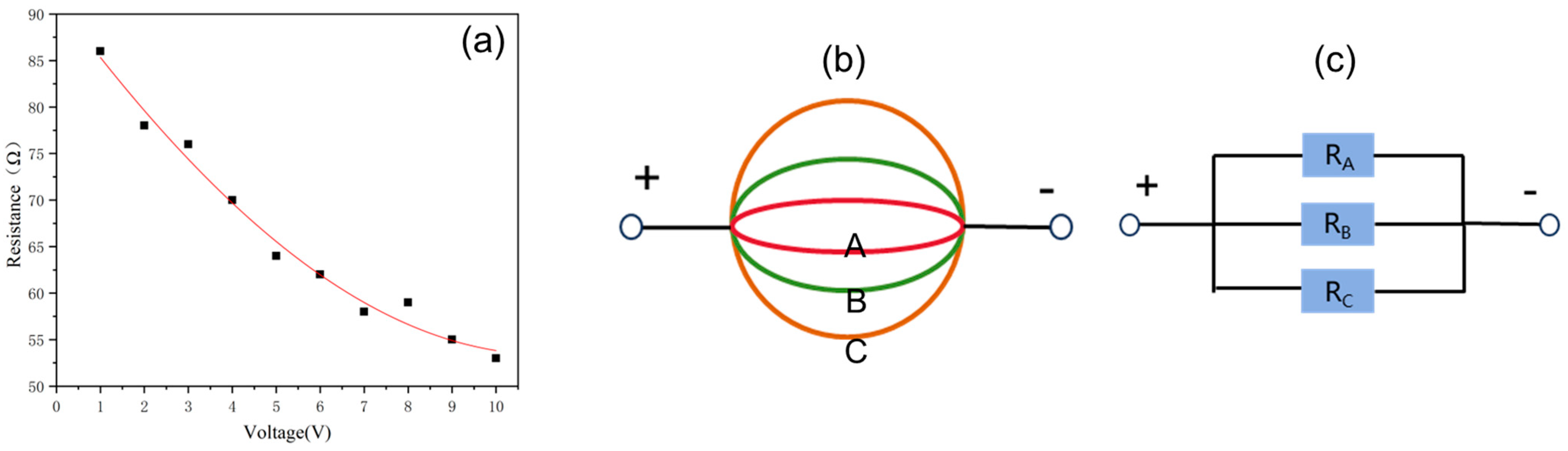
3.1. Equivalent Resistance Versus Voltage

Figure 1 shows the equivalent resistance versus voltage for a planar alumina electrothermal ceramic sheet with a sheet resistance of 27 Ω/sq. From Figure 1a, it can be seen that as the voltage increases, the equivalent resistance value becomes smaller, which is different from the conductivity of a metallic body. The reason for this phenomenon is that as the voltage increases, so does the electric field strength, and the film conductive area becomes larger. Figure 1b shows a schematic diagram of the conducting channel. It is assumed that the resistances of the conducting channels A, B, and C are RA, RB, and RC (RA < RB < RC), respectively, where the area enclosed by the red line, green line, and purple line are the conducting area of electrothermal films at low, medium, and high voltages, respectively. Figure 1c shows the equivalent circuit and the equivalent resistance of R is expressed by the equation of parallel resistance as:
1 R = 1 R A + 1 R B + 1 R C
According to Equation (1), In the case of one-power supply unit, a high supply voltage is required to obtain a low equivalent resistance, which indicated that high electrothermal power can be obtained only by using multi-power supply units at low voltages.

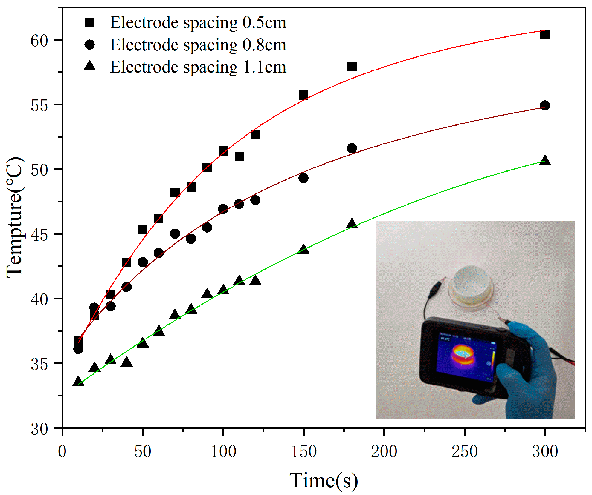
3.2. Influence of Electrode Spacing on Heating Efficiency

Figure 2 shows the electrothermal temperatures of the three-power supply units with electrode spacing of 0.5 cm, 0.8 cm, and 1.1 cm, respectively, with corresponding temperatures of 60.4 °C, 54.9 °C, and 50.6 °C after being supplied with 5 V for 300 s. The results show that the highest electrothermal efficiency can be obtained by powering the three-power supply units with the smallest electrode spacing, while the power supply unit with the largest electrode spacing has the smallest electrothermal efficiency. The reason is as follows: the resistance of R = ρ L t W for an electrothermal film, where ρ, L, t, and W represents the resistivity of an electrothermal film, the electrode spacing of the power supply unit, the thickness of electrothermal film, and the electrode width, respectively. Under a certain supply voltage, the smaller the R, the greater the power and, in turn, the higher the electrothermal efficiency.

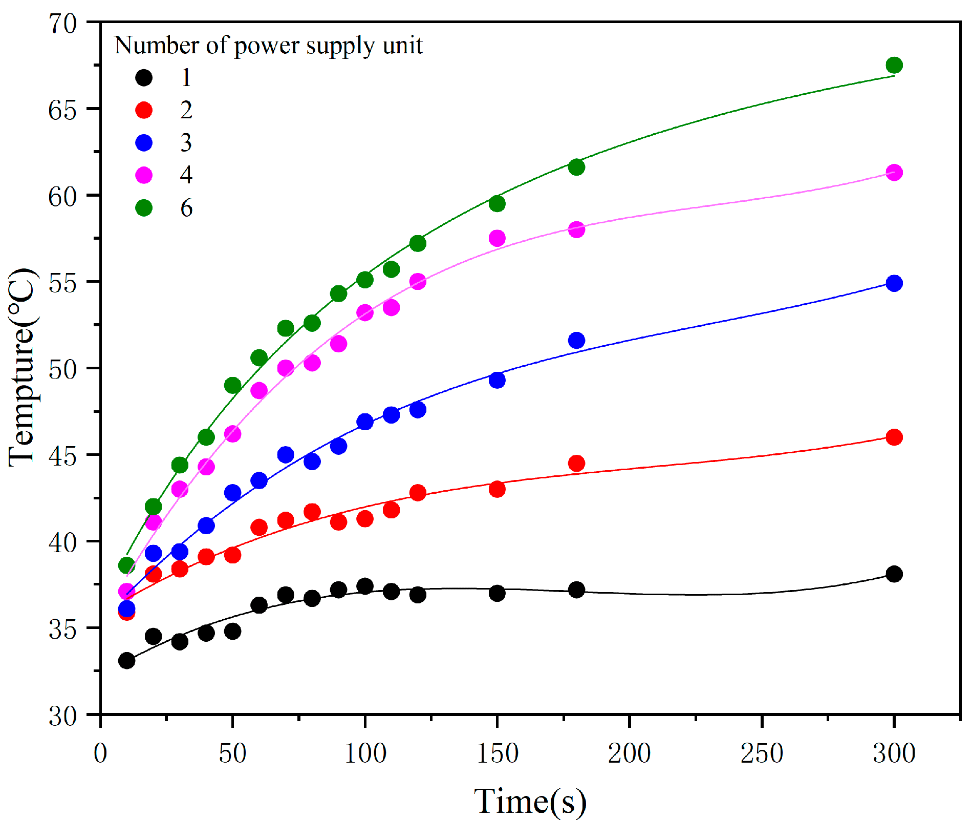
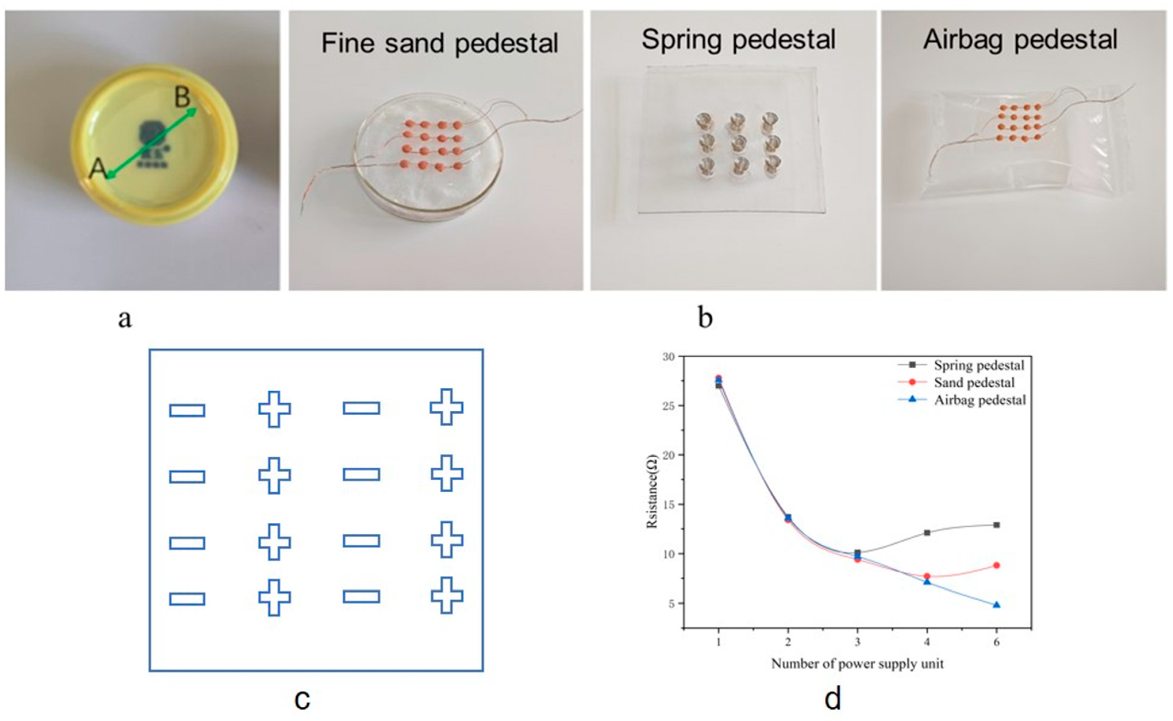
3.3. Relationship Between Power Supply Units and Heating Efficiency

Figure 3 shows the relationship between the number of power supply units and the electrothermal temperature with a supply voltage of 5 V and an electrode spacing of 0.8 cm. From Figure 3, it can be seen that the greater the number of power supply units, the higher the electrothermal efficiency. After 300 s of power, the number of power supply units are 1, 2, 3, 4, and 6, corresponding the electrothermal temperatures of 38.1 °C, 46 °C, 54.9 °C, 61.3 °C, and 67.5 °C, respectively. The relationship between the number of power supply units and the equivalent resistance and electrothermal power at different electrode spacing are summarized in Supplementary Material Table S1. Assuming that the input power, Pin, and resistance, R, of each power supply unit are the same, it can be seen from Table S1 that the output power, Pout, measured by the digital source meter is basically in direct proportion to the number of power supply units, n, which is basically consistent with the theoretical value of PS = n × Pin, where PS is the theoretical value of power. The equivalent resistance RM measured by the digital source meter is basically in inverse proportion to the number of power supply units, which is basically consistent with the theoretical value of Rp = R n , where Rp is the theoretical value of parallel resistance. Table S2 in Supplementary Material summarizes the P o u t P S P S of relative deviation between Pout and PS, and the R M R P R P of relative deviation between RM and Rp, respectively. As can be seen from Table S2, although the heating of electrothermal films using multi-power supply units with small electrode spacing has high electrothermal power, P o u t P S P S and R M R P R P increase as the number of multi-power supply units increases, with the numbers of multi-power supply units with the smallest electrode spacing of 0.5 cm being greater than that of three-power supply units. For example, when the numbers of multi-power supply units are six-power supply units, P o u t P S P S and R M R P R P is 21.6% and 21.7%, respectively. Although P o u t P S P S and R M R P R P of an electrothermal film, which was powered by multi-power supply units with the largest electrode spacing of 1.1 cm, has minimum values of 0.43% and 0.3%, respectively, the electrothermal efficiency is lower when multi-power supply units with a large electrode spacing is used to heat the electrothermal film under the same of the numbers of power supply units. With higher electrothermal power and lower P o u t P S P S , R M R P R P can be obtained by using multi-power supply units with a spacing of 0.8 cm to supply power electrothermal films.
The reasons why P o u t P S P S and R M R P R P are large when the electrothermal film was powered by numbers greater than three-power supply units and with smaller electrode space can be explained by the probability of poor contact. According to the analysis in Supplementary Material Section S3 the overall impact probability of poor contact between electrodes and electrothermal film is expressed as P(A) × p4, where P(A) is the probability that an electrode is too high and P is the probability of poor contact for each surrounding electrode with an electrothermal film. In the process of multi-power supply units participating in supplying power to the electrothermal film, if the electrode spacing of the multi-power supply unit is small, the probability P that one electrode is too high, resulting in poor contact for each surrounding electrode with the electrothermal film, is large. Assuming the probability P(A) that the electrode height is too high, the probability of poor contact for each surrounding electrode with the electrothermal film of multi-power supply units will also be high according to P(A) × p4, which results in a large deviation between the measured value of resistance and power and the theoretical value.

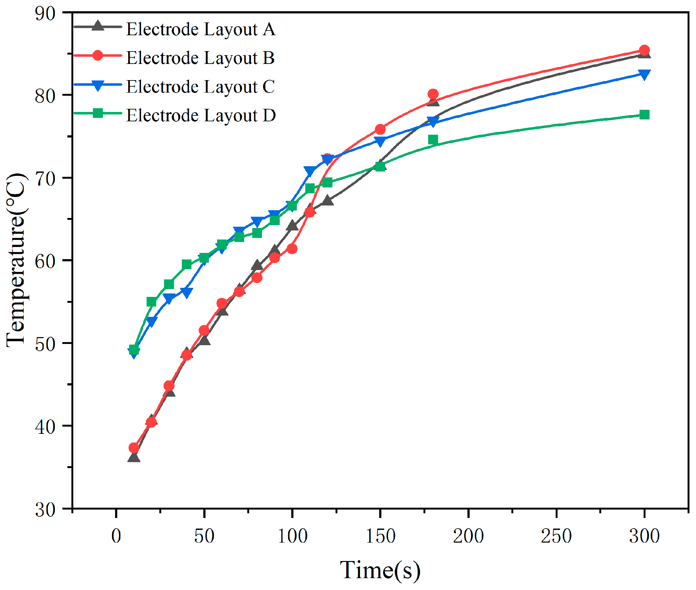
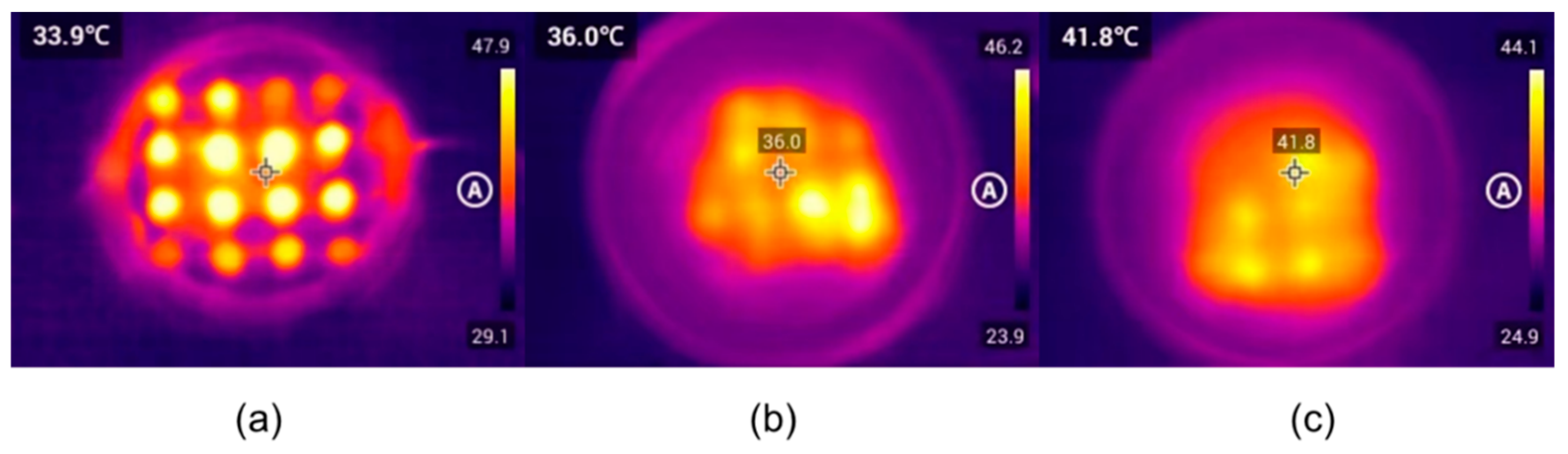
3.4. Influence of Multi-Power Supply Layout on Temperature Uniformity

Figure 4 shows the effect of a different layout of six-power supply units on temperature uniformity. The electrothermal films are powered according to A, B, C, and D electrode layout in Figure 4, and A1, B1, C1, and D1 correspond to the three-dimensional images of the temperature distribution on the surface of electrothermal films, respectively. The non-uniformity of temperature is defined as [24]:
T n o n - u n i f o r m i t y   = T M a x T m i n 2 T a v e   × 100 %
Tnon-uniformity refers to temperature uniformity, and Tmax, Tmin, and Tave represent the highest, lowest, and average temperatures, respectively. According to Equation (2), the temperature distribution inhomogeneities of the A, B, C, and D electrode layout are 15.7%, 16.8%, 29.5%, and 31.5%, respectively, which are also intuitively verified in Figure 4 A1, B1, C1, and D1. This result shows that the greater the number of branches of the circuit, the more uneven the temperature distribution caused by uneven currents. According to Kirchhoff’s current law (KCL), at any node in a circuit, at any given moment, the sum of the currents flowing into the node is equal to the sum of the currents flowing out of the node. With the electrode layout of mode A, the temperature distribution is the most uniform because the number of nodes of current inflow and outflow is equal. The number of nodes of inflowing current decreased in terms of B, C, and D, and the corresponding temperature inhomogeneity increased sequentially.
It is worth noting that the electrothermal efficiency will be different when the electrode layout of A, B, C, and D are used for power supply. As shown in Figure 5, after applying a continuous power supply to the electrothermal film for 30 s using A, B, C, and D layouts, the electrothermal temperatures are 84.9 °C, 85.4 °C, 82.0 °C, and 77.9 °C, respectively.
The reason for this phenomenon is that different electrode layouts of the multi-power supply units have different equivalent resistances. The equivalent resistances for the electrode layouts of A, B, C, and D are 5.5, 5.6, 6.6, and 8.1 Ω. For the electrothermal film, the equivalent resistance can be expressed as:
R = R s h L 2 S
where R, Rsh, L, and S represent the equivalent resistance, sheet resistance, electrode spacing, and area of electrothermal film, respectively. Assuming that the film areas between positive and negative electrodes of A, B, C, and D layout are SA, SB, SC, and SD, respectively, the corresponding equivalent resistances are RA, RB, RC, and RD, respectively. The area of A, B, C, and D layouts are expressed as SA > SB > SC > SD, as shown in Figure 4. RA < RB < RC < RD can be obtained according to Formula (3), similar to that of Rsh and L.

3.5. Heating Curved-Surface Electrothermal Ceramic Teacups

The bottom of a ceramic teacup generally has a curved surface due to the requirements of the firing process. After sputtering a layer of ITO film at its bottom, an electrothermal ceramic teacup with a curved surface electrothermal film is obtained, as shown in Figure 6a. The diameter of the electrothermal film is 5 cm, and the weight of the ceramic teacup is 45 g. The resistance measured along the diameters A and B, as shown in Figure 6a, is 42 Ω. In order to establish good contact between each electrode and the electrothermal film as much as possible when multi-power supply units are used to power the curved surface, power supply pedestals of fine sand, spring, and airbag are designed, respectively, as shown in Figure 6b. When each multi-power supply unit supplies power to the electrothermal film with a curved surface, the gravity of the ceramic teacup itself establishes good contact between the electrode and the electrothermal film through the deformation of fine sand, spring, and airbag, respectively. According to the above analysis of the influence of the multi-power supply unit layout on heating uniformity, the multi-power supply unit layout shown in Figure 6c is designed, which can not only ensure the uniformity of temperature, but also improve the electrothermal efficiency as much as possible.
Figure 6d shows the relationship between the number of power supply units with electrode spacing of 0.5 cm and the equivalent resistance of the electrothermal film when the electrothermal film is powered by a fine sand, spring, and airbag power supply pedestal, respectively. Curve C in Figure 6d shows that the equivalent resistance of the electrothermal film continues to decrease with the increase of the number of power supply units when the airbag power supply pedestal is used to supply power. Equivalent resistance conforms to the calculation of parallel resistance with an error of only ±0.5 Ω. For example, the equivalent resistance is 5.1 Ω for the six-power supply units, which is a 0.5 Ω difference from the theoretical value of 4.6 Ω calculated with a parallel resistance formula. It indicates that the contact between the electrode and the electrothermal film can still be well-established even under six-power supply units. For the number of power supply units ≤ 4, Curve D in Figure 6d shows that the equivalent resistance of the electrothermal film continues to decrease with the increase of the number of power supply units when the fine sand power supply pedestal is used to supply power. The equivalent resistance is basically in accordance with the calculation results of parallel resistance; however, when the number of power supply units is greater than 4, the equivalent resistance of the electrothermal film begins to rise. For the power supply pedestal with fine sand, Figure 6d indicates that each electrode can maintain good contact with the electrothermal film when the numbers of power supply units is less than 4. However, the surrounding electrodes will be in bad contact with the electrothermal film when the numbers of power supply units is greater than 4 such as six-power supply units due to one or more electrodes being too high. For the number of power supply units ≤ 3, Curve E in the figure shows that the equivalent resistance of the electrothermal film continues to decrease with the increase of the number of power supply units when the spring power supply pedestal is used to supply power. The equivalent resistance is basically in accordance with the calculation results of parallel resistance. However, when the number of power supply units is greater than 3, the equivalent resistance of the electrothermal film begins to rise. For the power supply pedestal with fine sand, Figure 6d indicates that each electrode can maintain good contact with the electrothermal film when the number of power supply units is less than 3. Based on the above analysis, and for the number of power supply units higher than 6, the electrode and the electrothermal film have the best contact when the airbag power supply pedestal is used to power the electrothermal film, while the electrode and the electrothermal film have the worst contact when the spring power pedestal is used to power the electrothermal film.
Figure 7a–c shows the thermographic images of the electrothermal film powered by airbag, fine sand, and spring power supply pedestals, respectively, after being energized for 10 s. As can be seen from Figure 7a, there are clearly 16 hotspots, which indicate that all 16 electrodes of airbag power supply pedestals are in good contact with the electrothermal film. It can be seen from Figure 7b,c that the electrodes have worse contact with the electrothermal film using fine sand and spring as the power supply pedestal instead of airbag.

4. Conclusions

In summary, for electrothermal films, the equivalent resistance decreases as the supply voltage increases. Meanwhile the equivalent resistance decreases as the electrode spacing decreases. The use of multi-power supply units for power supply can obtain high electrothermal power under a low voltage supply. However, the use of multi-power supply units for power supply results in poor contact between the electrodes and the electrothermal film, especially for electrothermal films with large areas, curved surfaces, and power supply units with small electrode spacing. When a few power supply units are used for power supply, the sand, spring, and airbag power supply pedestal can make the electrothermal film with a large area and curved surface come in close contact with the electrodes by deforming the sand, spring, or airbag due to the gravity of the heater. However, when a great number of power supply units are used, the airbag power supply pedestal is more effective than the sand or spring power supply pedestal in making contact between the electrothermal film and the electrode. Therefore, for a ceramic teacup with a curved-surface electrothermal film (20 cm2 area), the configuration employing 0.8 cm electrode spacing, 12 power supply units, and an airbag power supply pedestal achieves optimal electrothermal performance. Conversely, for planar electrothermal devices (5 cm × 5 cm), the combination of 0.5 cm electrode spacing, 16 power supply units, and a fine sand or spring power supply pedestal delivers satisfactory electrothermal efficiency while maintaining operational stability. The layout of multi-power supply units can affect the uniformity of the electrothermal temperature and the electrothermal efficiency; the larger the difference between the number of positive electrodes and the number of negative electrodes, the larger the non-uniformity of the electrothermal temperature and the smaller the electrothermal efficiency.

Supplementary Materials

The following supporting information can be downloaded at: https://www.mdpi.com/article/10.3390/coatings15050524/s1, Figure S1. Multi-power supply units. Figure S2. SEM image of ITO transparent conductive film. Table S1. The equivalent resistance and the electrothermal power for multi-power supply units with different electrode spacings. Table S2. The relative deviations of resistance and output power for multi-power supply units with different electrode spacings.

Author Contributions

Conceptualization, Y.D.; Methodology, Y.H. (Yefu Hu); Validation, X.X. and J.C.; Resources, H.L.; Data curation, Y.D., Y.H. (Yefu Hu), X.X., J.C. and Z.L.; Writing—original draft, Y.D.; Writing—review & editing, Y.H. (Yuehui Hu); Supervision, Y.H. (Yuehui Hu), H.L. and H.G.; Project administration, Y.H. (Yuehui Hu) and Y.C.; Funding acquisition, Y.H. (Yuehui Hu). All authors have read and agreed to the published version of the manuscript.

Funding

This work was funded by the Key R & D Program of Jiangxi Province, China (Grant No. 20232BBE50032), the Natural Science Foundation of Jiangxi Province, China (Grant Nos. 20202BAB202011, 2023BAB201035), the Education Bureau of Jiangxi Province, China (Grant Nos. GJJ2201003, GJJ211328, GJJ211319), and the National Natural Science Foundation of China (Grant Nos. 62041405, 12364014).

Institutional Review Board Statement

Not applicable.

Informed Consent Statement

Not applicable.

Data Availability Statement

Data are contained within the article and Supplementary Materials.

Conflicts of Interest

Author Yuehui Hu was employed by the company Jingdezhen Fuyu Qinghua Linglong Ceramics Co., Ltd. The remaining authors declare that the research was conducted in the absence of any commercial or financial relationships that could be construed as a potential conflict of interest.

References

  1. Xie, S.; Tu, L.; Han, Y.; Huang, L.; Kang, K.; Lao, K.U.; Poddar, P.; Park, C.; Muller, D.A.; DiStasio, R.A.; et al. Coherent, Atomically Thin Transition-Metal Dichalcogenide Superlattices with Engineered Strain. Science 2018, 359, 1131–1136. [Google Scholar] [CrossRef] [PubMed]
  2. Li, M.-Y.; Shi, Y.; Cheng, C.-C.; Lu, L.-S.; Lin, Y.-C.; Tang, H.-L.; Tsai, M.-L.; Chu, C.-W.; Wei, K.-H.; He, J.-H.; et al. Epitaxial Growth of a Monolayer WSe2-MoS2 Lateral p-n Junction with an Atomically Sharp Interface. Science 2015, 349, 524–528. [Google Scholar] [CrossRef] [PubMed]
  3. Duan, X.; Wang, C.; Shaw, J.C.; Cheng, R.; Chen, Y.; Li, H.; Wu, X.; Tang, Y.; Zhang, Q.; Pan, A.; et al. Lateral Epitaxial Growth of Two-Dimensional Layered Semiconductor Heterojunctions. Nat. Nanotechnol. 2014, 9, 1024–1030. [Google Scholar] [CrossRef] [PubMed]
  4. Liu, Y.; Duan, X.; Shin, H.-J.; Park, S.; Huang, Y.; Duan, X. Promises and Prospects of Two-Dimensional Transistors. Nature 2021, 591, 43–53. [Google Scholar] [CrossRef]
  5. Mehrali, M.; Bagherifard, S.; Akbari, M.; Thakur, A.; Mirani, B.; Mehrali, M.; Hasany, M.; Orive, G.; Das, P.; Emneus, J.; et al. Blending Electronics with the Human Body: A Pathway toward a Cybernetic Future. Adv. Sci. 2018, 5, 1700931. [Google Scholar] [CrossRef]
  6. Ling, Y.; An, T.; Yap, L.W.; Zhu, B.; Gong, S.; Cheng, W. Disruptive, Soft, Wearable Sensors. Adv. Mater. 2020, 32, 1904664. [Google Scholar] [CrossRef]
  7. Abiri, P.; Luo, Y.; Huang, Z.-Y.; Cui, Q.; Duarte-Vogel, S.; Roustaei, M.; Chang, C.-C.; Xiao, X.; Packard, R.; Cavallero, S.; et al. 3-Dimensional Electrical Impedance Spectroscopy for in Situ Endoluminal Mapping of Metabolically Active Plaques. Sens. Actuators B Chem. 2022, 354, 131152. [Google Scholar] [CrossRef]
  8. Wang, S.; Nie, Y.; Zhu, H.; Xu, Y.; Cao, S.; Zhang, J.; Li, Y.; Wang, J.; Ning, X.; Kong, D. Intrinsically Stretchable Electronics with Ultrahigh Deformability to Monitor Dynamically Moving Organs. Sci. Adv. 2022, 8, eabl5511. [Google Scholar] [CrossRef]
  9. Liu, W.; Hu, Y.; Chen, Y.; Hu, Z.; Zhou, K.; Min, Z.; Liu, H.; Zhan, L.; Dai, Y. Improvement of Electrical Properties of Silver Nanowires Transparent Conductive by Metal Oxide Nanoparticles Modification. Coatings 2022, 12, 1816. [Google Scholar] [CrossRef]
  10. Hu, Y.; Wu, W. Investigation of Silver Nanowire Transparent Heated Films Possessing the Application Scenarios for Electrothermal Ceramics. Coatings 2023, 13, 607. [Google Scholar] [CrossRef]
  11. Zhou, K.; Hu, Y.; Chen, Y.; Hu, Z.; Hu, Y.; Liu, W.; Min, Z. Surface Modification of Silver Nanowire Transparent Conductive Films by Metal Oxide Nanoparticles and the Application of Electric Ceramic Teacup. Ceram. Int. 2023, 49, 14530–14537. [Google Scholar] [CrossRef]
  12. Zhang, Y.; Yang, F.; Liu, H.; Zhang, Y.; Hu, Z.; Liu, J. Transparent Heaters Based on CVD Grown Few-Layer Graphene. J. Mater. Sci. Mater. Electron. 2022, 33, 3586–3594. [Google Scholar] [CrossRef]
  13. Zhao, Y.; Niu, M.; Yang, F.; Jia, Y.; Cheng, Y. Ultrafast electro-thermal responsive heating film fabricated from graphene modified conductive materials. Eng. Sci. 2019, 8, 33–38. [Google Scholar] [CrossRef]
  14. He, R.; Fang, D.; Wang, P.; Zhang, X.; Zhang, R. Electrical Properties of ZrB2–SiC Ceramics with Potential for Heating Element Applications. Ceram. Int. 2014, 40, 9549–9553. [Google Scholar] [CrossRef]
  15. Han, J.; Hu, P.; Zhang, X.; Meng, S.; Han, W. Oxidation-Resistant ZrB2–SiC Composites at 2200 °C. Compos. Sci. Technol. 2008, 68, 799–806. [Google Scholar] [CrossRef]
  16. Sui, D.; Huang, Y.; Huang, L.; Liang, J.; Ma, Y.; Chen, Y. Flexible and Transparent Electrothermal Film Heaters Based on Graphene Materials. Small 2011, 7, 3186–3192. [Google Scholar] [CrossRef]
  17. Ma, Z.; Kang, S.; Ma, J.; Shao, L.; Wei, A.; Liang, C.; Gu, J.; Yang, B.; Dong, D.; Wei, L.; et al. High-Performance and Rapid-Response Electrical Heaters Based on Ultraflexible, Heat-Resistant, and Mechanically Strong Aramid Nanofiber/Ag Nanowire Nanocomposite Papers. ACS Nano 2019, 13, 7578–7590. [Google Scholar] [CrossRef]
  18. Sannicolo, T.; Lagrange, M.; Cabos, A.; Celle, C.; Simonato, J.; Bellet, D. Metallic Nanowire-Based Transparent Electrodes for Next Generation Flexible Devices: A Review. Small 2016, 12, 6052–6075. [Google Scholar] [CrossRef]
  19. Pavlov, D.V.; Il’yaschenko, V.M.; Bozhok, A.V.; Banniy, D.E.; Kuchmizhak, A.A.; Shevlyagin, A.V. Transparent Microheater Enabled by Laser Perforation of the Thin CaSi2 Film. Bull. Russ. Acad. Sci. Phys. 2024, 88, S418–S422. [Google Scholar] [CrossRef]
  20. Yu, S.; Liu, X.; Dong, H.; Wang, X.; Li, L. Flexible High-Performance SnO2/AgNWs Bilayer Transparent Conductors for Flexible Transparent Heater Applications. Ceram. Int. 2021, 47, 20379–20386. [Google Scholar] [CrossRef]
  21. Zheng, B.; Zhu, Q.; Zhao, Y. Fabrication of High-Quality Silver Nanowire Conductive Film and Its Application for Transparent Film Heaters. J. Mater. Sci. Technol. 2021, 71, 221–227. [Google Scholar] [CrossRef]
  22. Wang, P.; Jian, M.; Wu, M.; Zhang, C.; Zhou, C.; Ling, X.; Zhang, J.; Yang, L. Highly Sandwich-Structured Silver Nanowire Hybrid Transparent Conductive Films for Flexible Transparent Heater Applications. Compos. Part A Appl. Sci. Manuf. 2022, 159, 106998. [Google Scholar] [CrossRef]
  23. Papanastasiou, D.T.; Schultheiss, A.; Muñoz-Rojas, D.; Celle, C.; Carella, A.; Simonato, J.; Bellet, D. Transparent Heaters: A Review. Adv. Funct. Mater. 2020, 30, 1910225. [Google Scholar] [CrossRef]
  24. Kim, A.-Y.; Kim, M.K.; Hudaya, C.; Park, J.H.; Byun, D.; Lim, J.C.; Lee, J.K. Oxidation-Resistant Hybrid Metal Oxides/Metal Nanodots/Silver Nanowires for High Performance Flexible Transparent Heaters. Nanoscale 2016, 8, 3307–3313. [Google Scholar] [CrossRef]
Figure 1. (a) The relationship between voltage and resistance of planar alumina electrothermal ceramic sheet. (b) Schematic diagram of the conducting channels. The area enclosed by the red line (A), green line (B), and purple line (C) are the conducting area of electrothermal films at low, medium, and high voltages, respectively. (c) Equivalent circuits of electrothermal films at high voltages.
Coatings 15 00524 g001
Figure 2. Electrothermal temperature for different electrode spacing.
Coatings 15 00524 g002
Figure 3. The relationship between electrothermal temperature and time for different multi-power supply units.
Coatings 15 00524 g003
Figure 4. Influence of multi-power supply unit layout on the uniformity of electrothermal temperature.
Coatings 15 00524 g004
Figure 5. Electrothermal temperatures of different electrode layouts.
Coatings 15 00524 g005
Figure 6. (a) Photograph of an electrothermal ceramic teacup; (b) photograph of the power supply pedestal of fine sand, spring and airbag; (c) schematic diagram of the electrode layout; (d) equivalent resistance of electrothermal film for powering with different power supply pedestals.
Coatings 15 00524 g006
Figure 7. Thermographic imaging of electrothermal film powering with an airbag, fine sand, and spring power pedestal. (a) Thermographic imaging of powering with an airbag pedestal, (b) thermographic imaging of powering with fine sand pedestal, and (c) thermographic imaging of powering with spring pedestal.
Coatings 15 00524 g007
Disclaimer/Publisher’s Note: The statements, opinions and data contained in all publications are solely those of the individual author(s) and contributor(s) and not of MDPI and/or the editor(s). MDPI and/or the editor(s) disclaim responsibility for any injury to people or property resulting from any ideas, methods, instructions or products referred to in the content.

