Abstract
The coupled factors of high temperature, high humidity, and high salinity in tropical marine atmospheres severely threaten the long-term service performance of power transmission and transformation infrastructure. This paper establishes an accelerated cyclic testing protocol (salt spray → drying → damp heat → drying) to evaluate performance and elucidate the dynamic corrosion failure mechanisms of the organic Zn14Al1.4 composite coating. By integrating multiphysical characterization techniques (SEM, EDS, XPS) with electrochemical analysis, this study for the first time elucidates the dynamic transformation of corrosion products: initially dominated by Zn(OH)2, progressing to complex passive phases such as Zn5(OH)8Cl2·H2O, Zn5(OH)6(CO3)2, and Zn6Al2(OH)16CO3 in the mid-term, and ultimately dominated by Fe-based products (FeO, Fe2O3, Fe3O4, FeOOH) that drive interfacial failure. And a four-stage corrosion evolution model was defined: incubation period, accelerated degradation phase, substrate nucleation stage, and catastrophic failure phase. The investigation reveals a shift in the coating/substrate interface failure mechanism from purely physical barrier effects to electrochemical synergy, providing a theoretical framework for the optimized design and service-life prediction of anticorrosive coatings for transmission and transformation equipment in tropical environments.
1. Introduction
Power transmission and transformation equipment, as a critical component of the electrical grid, plays a vital role in ensuring the stable delivery of electricity. However, when operating in tropical marine atmospheres characterized by high temperature, high humidity, heavy rainfall, and elevated salinity, severe corrosion challenges arise for the metallic substrates and protective coatings of transmission and transformation equipment [1,2,3]. Under these extreme conditions, protective coatings on metal structures are prone to premature failure, resulting in localized corrosion [4,5], pitting [6,7], and even stress corrosion cracking [8,9] of the substrate, thereby jeopardizing both the safe operation and long-term service life of transmission and transformation assets. Therefore, conducting effective corrosion protection research is essential for enhancing the reliability and durability of power transmission and transformation equipment.
To mitigate metal corrosion, organic–metal composite coatings, such as epoxy zinc-rich primers, have been widely employed in engineering applications [10,11,12]. Among these, Zn-Al epoxy coatings synergistically combine multiple protective mechanisms: (1) the sacrificial anode protection provided by zinc, which preferentially corrodes to protect the underlying substrate cathodically; (2) the enhanced self-healing capacity from aluminum, which facilitates the formation of a passive oxide film; and (3) the robust physical barrier afforded by the dense epoxy resin matrix, effectively blocking the ingress of corrosive species [13,14,15]. Optimizing the metal phase morphology and composition significantly improves performance. Zhang et al. [16] demonstrated that substituting pure zinc with flake Zn-Al alloy particles prolonged the sacrificial protection duration. This flake morphology also induces a beneficial “maze effect”, substantially extending the diffusion pathways for corrosive ions. Furthermore, Ding et al. [17] found that increasing the aluminum content promotes the formation of layered double hydroxides (LDH) incorporating Zn2+ and Al3+, compounds known to enhance the coating’s corrosion resistance further. The specific phase structure of the Zn-Al alloy plays a critical role in LDH formation and corrosion behavior. Kirsten et al. [18] observed that the β-ZnAl15 phase consistently developed a uniform, protective LDH layer during salt spray testing. In contrast, the α-η-ZnAl15 phase exhibited heterogeneous corrosion under identical conditions. Significantly, the LDH layer serves as an effective secondary barrier, inhibiting the penetration of corrosive media into the coating interior and suppressing the oxygen reduction reaction rate [19], thereby demonstrating superior protection for metallic components [20,21,22].
Although considerable research has been conducted on the corrosion behavior of Zn-Al epoxy coatings, most studies have focused on single environmental factors (e.g., salt spray [16,23,24], damp heat [25,26], or solution immersion [27,28,29,30]), lacking a systematic analysis of the synergistic effects in tropical marine atmospheres. In fact, high-temperature and high-humidity conditions can break the chemical bonds of the organic molecular chains in the epoxy coating, causing water uptake, swelling, relaxation and rupture of the cross-linked network, and increased porosity [31,32,33]; meanwhile, chloride ions concentrate at the coating–metal interface via capillary action during wet–dry cycles, disrupting the passive film and exacerbating electrochemical corrosion of the metal substrate [34,35,36].
This study, set against the backdrop of power transmission and transformation equipment (such as transmission and substation towers, large transformer casings, etc.) in tropical marine atmospheres, investigates the complex multi-factor-coupled corrosion mechanisms of an organic Zn14Al1.4 composite coating. To achieve this goal, an innovative indoor acceleration testing system was adopted, specifically designed to collaboratively replicate key environmental pressure factors encountered in these areas, such as high temperature, humidity, and salt spray. By examining macroscopic coating morphology, monitoring fundamental property changes, analyzing electrochemical behavior, and characterizing corrosion products and layer structures, the research revealed the characteristic corrosion failure process (comprising four distinct stages) of the Zn14Al1.4 organic composite coating under synergistic stress conditions representative of tropical marine environments. The findings provide valuable data for applying this coating in highly corrosive tropical power grids.
2. Materials and Methods
2.1. Materials
The organic Zn14Al1.4 composite coating used in this study was supplied by the State Grid Corporation of China (Beijing, China).
The coating consists of the following components by mass fraction: 65.85% organic components, 14.14% flake-shaped zinc powder, 1.41% flake-shaped aluminum powder, 3.89% other additives, and 14.71% solvent.
After thoroughly mixing the aforementioned components, the mixture is stirred and dispersed in a high-shear disperser at 450 rpm for 2–4 h to form a homogeneous organic zinc–aluminum alloy coating solution. Subsequently, the coating solution is sprayed onto the surface of a Q235B carbon steel plate (see Table 1 for specific composition details). Initial surface-dried curing is performed at 150 °C for 30 min, followed by temperature elevation to 260 °C for final curing lasting 15–20 min.

Table 1.
Chemical composition of Q235B carbon steel.
To effectively prevent atypical corrosion morphologies (edge effect) induced by specimen corners during corrosion testing, all specimens underwent rigorous “edge-sealing” treatment with 3M vinyl electrical tape (3M China, Shanghai, China) on the back surface, edges, and peripheral areas of the front surface prior to testing. To eliminate intrusion of moisture and contaminant ions through gaps between the sealing tape and specimen, K9119 foundry adhesive (Kafuter, Guangzhou, China) was meticulously applied to seal all tape–specimen interfaces.
2.2. Simulated Tropical Marine Atmospheric Corrosion Test
The accelerated corrosion test was designed to simulate tropical marine atmospheric conditions, comprising ten cycles of “salt spray → drying → damp heat → drying,” as illustrated in Figure 1. The conditions for the salt spray, damp heat, and drying tests are specified as follows:
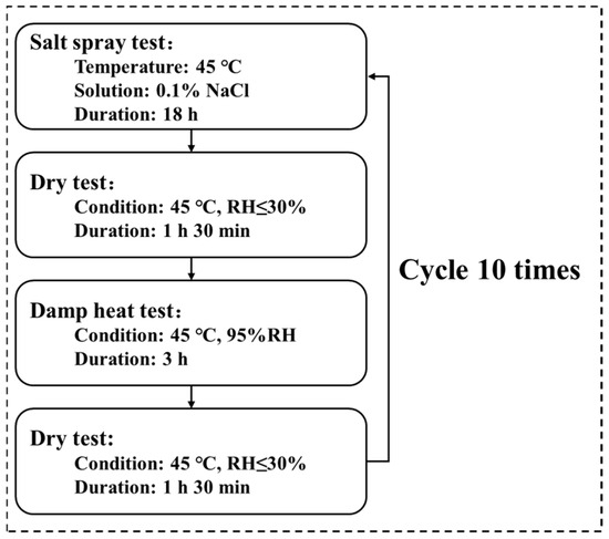
Figure 1.
Flowchart of the simulated tropical marine atmospheric corrosion test.
- Salt spray test: conducted at 45 °C using a 0.1 wt.% NaCl (Aladdin, Shanghai, China) solution (pH 6.0) for 18 h.
- Damp heat test: performed at 45 °C and 95% relative humidity for 3 h.
- Drying test: added after the salt spray and damp heat phases to better replicate natural wet–dry alternation of the organic Zn14Al1.4 composite coating; conducted at 45 °C and <30% relative humidity for 1 h 30 min.
2.3. Fundamental Performance Testing of the Coating
- (1)
- Thickness: The thickness of samples was measured using a QNIX4500 (QNix, Cologne, Germany) coating thickness gauge, and the initial thickness values were recorded. Thereafter, samples were re-measured at the end of each test cycle to assess coating thickness changes over successive cycles. During thickness testing, measurements were taken at the one-quarter, one-half, and three-quarter positions of each specimen. The three measurements were averaged to obtain the mean thickness for each sample.
- (2)
- Color Difference: A spectrophotometer (3nh, Guangzhou, China) was used to measure the initial tristimulus values (L, a, b) of all specimens, and the results were recorded. Subsequently, tristimulus values (L*, a*, b*) were re-measured after each test cycle, and the color difference (ΔE) over cycles was calculated using Formula (1) [37]. Tristimulus measurements were taken at the one-quarter, one-half, and three-quarter positions of each specimen. The three readings were averaged to yield the mean tristimulus values for each sample.
- (3)
- Adhesion: Adhesion strength before testing (F0, MPa) and after each corrosion cycle (Fc, MPa) was measured with a Positest AT-A 20 automated pull-off adhesion tester (DeFelsko, New York, NY, USA), and macroscopic surface morphology was documented with a Nikon D7000 digital camera (Nikon, Tokyo, Japan). The percentage loss of adhesion (ΔF, %) was calculated using Formula (2) to evaluate adhesion changes over corrosion cycles.
2.4. Corrosion Morphology
After each cycle of the simulated tropical marine corrosion test, the macroscopic corrosion morphology of the sample surfaces was captured with a Nikon D7000 camera. A color-threshold binary segmentation approach was then applied: images were converted from BGR to HSV color space to isolate the reddish-brown hue and quantitatively assess the corroded area.
A FEI Quanta250 scanning electron microscope (SEM) (ThermoFisher, Waltham, MA, USA) was used to examine the surface and cross-sectional micro-morphology of the corrosion layers, and energy-dispersive spectroscopy (EDS) was employed for elemental analysis of the corrosion products.
2.5. Electrochemical Performance
Electrochemical tests were performed with a PARSTAT 4000A workstation (Princeton Applied Research, Princeton, NJ, USA) on a 0.785 cm2 exposed area of each sample. Open-circuit potential (OCP) was recorded for 1800 s to ensure system stabilization; electrochemical impedance spectroscopy (EIS) was conducted over the frequency range of 0.01 Hz to 100 kHz with an AC amplitude of 10 mV.
2.6. Corrosion Products Composition
X-ray photoelectron spectroscopy (XPS) analysis of the organic Zn14Al1.4 composite coating surface and corrosion products were conducted using an ESCALAB Xi+ spectrometer (ThermoFisher, Waltham, MA, USA). The X-ray source was monochromatic Al Kα radiation with a 650 µm spot size. High-resolution spectra were acquired for Zn, Fe, Al, O, and Cl regions and analyzed using Avantage 5.9921 software. The binding energy scale was calibrated using the C1s peak at 284.8 eV.
3. Results and Discussion
3.1. Macroscopic Corrosion Morphology
Figure 2 illustrates the evolution of the macroscopic corrosion morphology of the organic Zn14Al1.4 composite coatings at different cycles of the simulated tropical marine atmospheric corrosion test. To quantify the extent of surface corrosion, a color-threshold binary segmentation method was applied to the macroscopic images (Figure 3), where black regions denote uncorroded areas and white regions indicate surfaces covered by reddish-brown corrosion products. Quantitative analysis of the corroded area fraction (Table 2) shows that the coverage of corrosion products on the organic Zn14Al1.4 composite coatings surface increase markedly with the number of test cycles.
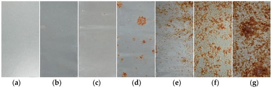
Figure 2.
Macroscopic morphology of the organic Zn14Al1.4 composite coatings in the simulated tropical marine atmospheric corrosion test: (a) untested, (b) cycle 1, (c) cycle 2, (d) cycle 3, (e) cycle 4, (f) cycle 5, and (g) cycle 6.
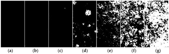
Figure 3.
Binary segmentation results of the macroscopic morphology of the organic Zn14Al1.4 composite coatings in the simulated tropical marine atmospheric corrosion test: (a) untested, (b) cycle 1, (c) cycle 2, (d) cycle 3, (e) cycle 4, (f) cycle 5, and (g) cycle 6.
Table 2.
Proportion of corroded area calculated by binary segmentation.
The progression can be divided into distinct stages: during the initial stage (cycles 1 and 2), the coating shows no discernible corrosion (corroded area fraction < 0.05%), indicating that its dense physical barrier effectively blocks Cl−, H2O, and other corrosive species, preventing significant corrosion of the carbon steel substrate. In the coating damage stage (cycle 3), multiple localized pits appear and the corroded area fraction rises to 5.0%, indicating that micro-pores or defects in the coating have lost their protective function due to prolonged ingress of corrosive media, exposing the substrate to electrochemical corrosion and causing reddish-brown corrosion products (e.g., iron oxides) to accumulate at weak spots. During the corrosion acceleration stage (cycles 4 and 5), the corroded area fraction sharply increases to 12.92% (cycle 4) and 37.24% (cycle 5), accompanied by the formation of bulges on the coating surface. These observations indicate that continued corrosion of the carbon steel substrate leads to accumulation of corrosion products at the coating–substrate interface, whose volumetric expansion generates internal stresses [38] that weaken the coating’s adhesion and ultimately cause blistering and localized delamination. At this point, the coating’s physical barrier function has become partially compromised. In the full failure stage (cycle 6), the coating’s integrity is completely lost (corroded area fraction reaches 69.65%), with extensive delamination visible on the surface, indicating a significant acceleration of localized electrochemical corrosion. At this stage, the synergistic effect of localized corrosion propagation (e.g., pit coalescence) and expansion stress from accumulated corrosion products causes the coating to detach from the substrate, resulting in complete loss of protective function.
3.2. Fundamental Properties
Figure 4 illustrates the thickness evolution of the organic Zn14Al1.4 composite coatings after each cycle of the simulated tropical marine atmospheric corrosion test. The results indicate that the coating thickness exhibits a three-stage growth characteristic of “latent accumulation, accelerated expansion, unstable detachment”, and its evolution law is closely related to the substrate corrosion process and product accumulation effect.
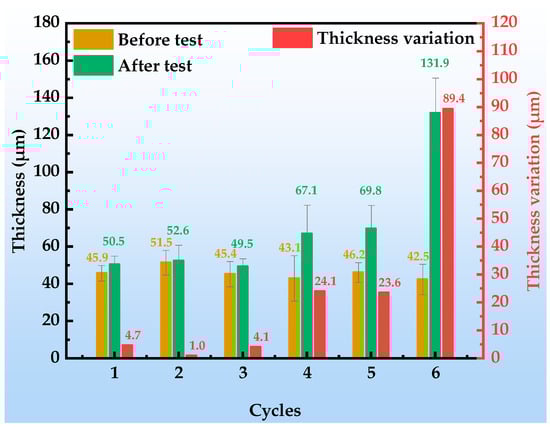
Figure 4.
Thickness of and variation in the organic Zn14Al1.4 composite coatings during the simulated tropical marine atmospheric corrosion test.
In the initial stage (cycles 1~3), the increase in coating thickness is slight (cumulative increase < 5 μm), and the observed thickness variations are mainly attributed to the inherent non-uniformity of the coating itself. During this stage, no significant corrosion products form on the coating surface (area fraction < 5%), indicating that the coating still maintains a dense physical barrier; the corrosion reactions occur only at localized weak points (e.g., pores, crack tips) and remain at a metastable nucleation phase, without inducing any notable volumetric effects. In the middle stage (cycles 4~5), the thickness increment increases markedly to 23.6~24.1 μm, a phenomenon closely associated with the activation of corrosion reactions at the substrate/coating interface; at this point, the volumetric expansion of underfilm corrosion products dominates the thickness evolution, as the oxidized products generated beneath the coating exert an outward expansion owing to their volume increase [39,40], causing a rapid macroscopic thickening of the coating. Notably, the thickness increment during this stage shows a positive correlation with the corrosion area fraction (12.92~37.24%), confirming the coupling mechanism of product accumulation and coating expansion. In the late stage (cycle 6), the coating thickness surges to 89.4 μm, during which underfilm corrosion products accumulate exponentially (corroded area fraction reaches 62%); their porous, loose structure provides rapid pathways for Cl−, O2, and H2O penetration, accelerating interfacial ion migration and exacerbating electrolyte permeation and ion exchange at the interface. The resulting thickness expansion induces stresses that exceed the organic resin’s adhesive strength, ultimately causing delamination at the coating/substrate interface.
As shown in Figure 5, with the progression of the simulated tropical marine atmospheric corrosion test cycles, the color difference (ΔE) of the organic Zn14Al1.4 composite coatings exhibits pronounced stage-specific evolution characteristics. In cycle 1, the change in color difference is minimal (ΔE < 5), and no obvious corrosion products or substrate erosion are observed on the coating surface, indicating that the coating still maintains an intact physical barrier function and effectively prevents penetration of corrosive media. In cycles 2~3, the ΔE value increases into the range of 10~15, and corrosion morphology observations reveal the onset of localized reddish-brown corrosion products (Fe-based oxides) on the surface, concurrent with a trend of cumulative coating thickness growth. During this stage, the ΔE variation is strongly correlated with micro-morphological evolution: the localized distribution and altered optical properties of the corrosion products directly shift the surface reflection spectrum, while the non-uniform growth in coating thickness further intensifies light-scattering effects, jointly driving the color difference into a phase of moderate increase. In cycles 4~6, the ΔE surges to values greater than 20, and macroscopic morphology shows blistering and spalling of the coating as well as extensive accumulation of corrosion products, particularly with a thickness increment reaching 89.4 μm in cycle 6. The dramatic increase in ΔE at this stage arises from two synergistic factors: first, the accumulation of reddish-brown iron-based products significantly alters the surface color characteristics; and second, physical defects in the coating, such as cracks and peeling, form a “self-catalytic effect” [41,42], leading to intensified corrosion reactions and nonlinear changes in optical reflection characteristics.
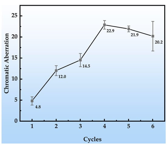
Figure 5.
Color difference changes in the organic Zn14Al1.4 composite coatings during the simulated tropical marine atmospheric corrosion test.
Figure 6 presents the dynamic decay behavior of the bond strength of the organic Zn14Al1.4 composite coatings during the simulated tropical marine atmospheric corrosion test. Figure 7 shows the macroscopic underfilm morphology and spallation appearance of the coating after adhesion testing. The coating’s initial adhesion strength reaches 5.34 MPa, demonstrating excellent interfacial bonding performance. After the first cycle, the adhesion strength drops sharply to 2.88 MPa (a decrease of approximately 45.2%); although no corrosion products are visible in the underfilm macroscopic morphology (Figure 7a,b), the strength reduction indicates that corrosive media have penetrated through micropores or interfacial defects, initiating early weakening of the organic resin/metal interface. In the second cycle, the adhesion strength further declines to 0.75 MPa and remains unstable, corresponding to the appearance of diffusely distributed shallow corrosion products beneath the film (Figure 7c). At this stage, Cl− and H2O concentrate at the interface via permeation pathways, inducing preferential corrosion of the Zn/Al components and the formation of products such as Zn(OH)2 and Al2O3. Their volumetric expansion effect leads to stress concentration at the interface, accelerating bond failure. During cycles 3~6, the adhesion strength stabilizes at a low level of around 1.0 MPa (a decrease exceeding 75.0%), and the underfilm corrosion products evolve into dark reddish-brown Fe-based oxides (Figure 7d–g). This phenomenon reveals that the corrosion process has breached the protective coating layer, causing anodic dissolution of the substrate Fe (Fe → Fe2+ + 2e−); the resulting Fe-based products, due to molar volume differences (the volumetric expansion ratio of corrosion products is from 2.71 to 3.97 [43]), generate internal stress fields at the interface, ultimately leading to blistering, delamination, and macroscopic spallation of the coating. Consequently, the properties of the corrosion product layer itself and the interfacial bonding strength at the coating interface progressively become the dominant factors controlling peel strength. The separation resistance provided by these fracture surfaces remains relatively stable and exhibits low sensitivity to accumulated damage from subsequent cyclic corrosion (at least within the six test cycles), resulting in fluctuating adhesion data.
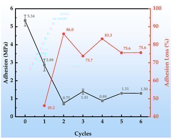
Figure 6.
Adhesion changes in the organic Zn14Al1.4 composite coatings during the simulated tropical marine atmospheric corrosion test.
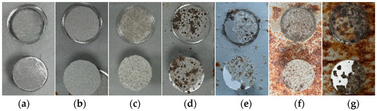
Figure 7.
Macroscopic underfilm morphology and spallation appearance of the organic Zn14Al1.4 composite coatings after adhesion testing: (a) untested, (b) cycle 1, (c) cycle 2, (d) cycle 3, (e) cycle 4, (f) cycle 5, and (g) cycle 6.
The above evolution indicates that the essence of coating failure is a chain reaction process of “penetration → corrosion product accumulation → interfacial stress destabilization,” and the decay of adhesion strength can serve as a quantitative indicator of the chemo-mechanical co-degradation at the interface.
3.3. Microscopic Corrosion Morphology
Figure 8 illustrates the evolution of the surface micro-morphology of the organic Zn14Al1.4 composite coatings at different cycles during the simulated tropical marine atmospheric corrosion test, and combined with the quantitative EDS elemental analysis in Table 3, reveals the staged characteristics of the corrosion process.
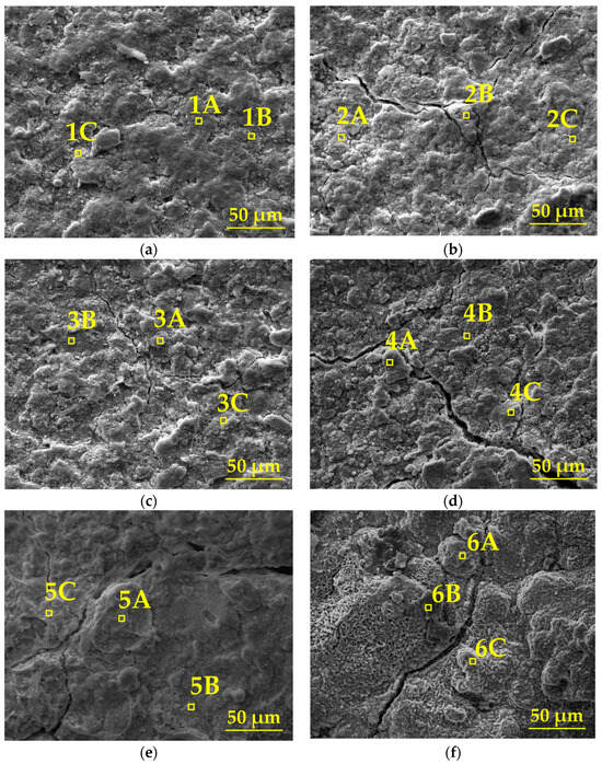
Figure 8.
SEM morphology of the organic Zn14Al1.4 composite coatings in the simulated tropical marine atmospheric corrosion test: (a) cycle 1, (b) cycle 2, (c) cycle 3, (d) cycle 4, (e) cycle 5, and (f) cycle 6.
Table 3.
EDS results at different positions and cycles of the organic Zn14Al1.4 composite coatings in the simulated tropical marine atmospheric corrosion test.
In the first cycle, SEM images show a dense and defect-free surface (Figure 8a), and EDS analysis indicates that the coating mainly consists of Zn (39.6%~76.1%) and Al (5.3%~14.4%), with the presence of O (16.7%~44.0%) and trace amounts of Fe (≤0.9%) and Cl (≤2.0%), confirming the coating’s excellent physical barrier and electrochemical protection capabilities in its initial state. In cycles 2~3, the surface morphology deteriorates significantly: a network of cracks and spot-like corrosion products begins to emerge (Figure 8b,c), and EDS detects a local increase in Fe (0%~1.6%) and Cl (0.5%~7.2%) content, indicating that Cl− has infiltrated the interface through microcracks, initiating the preferential dissolution of Zn (Zn → Zn2+ + 2e−) and the onset of Fe substrate corrosion (Fe → Fe2+ + 2e−). In cycles 4~5, cracks expand to 10~20 μm, accompanied by the formation of bulky protrusions (Figure 8d,e). The Zn and Al content drops sharply to 24.7%~42.4% and 3.9%~9.9%, while Fe (9.7%~37.7%) and O (34.1%~60.3%) are significantly enriched, confirming that the corrosion reaction has penetrated the coating/substrate interface. The formation of Fe(OH)2/FeOOH and other products induces interfacial stress due to volumetric expansion, accelerating coating delamination. In the sixth cycle, the surface exhibits a porous, honeycomb-like structure (Figure 8f), with Zn/Al signals nearly disappearing (Zn: 0.6%~6.5%; Al: 0%~0.7%). Fe content surges to 69.2%~76.4%, while the distribution of O (20.2%~28.1%) and Cl (0%~4.1%) indicates that corrosion has entered the occluded cell stage, where the enrichment of Fe3+/Cl− induces acidification, ultimately resulting in complete loss of the coating’s protective function.
The interface corrosion evolution mechanism of the organic Zn14Al1.4 composite coatings in a simulated tropical marine atmospheric environment is elucidated by SEM cross-section morphology and EDS elemental mapping (Figure 9). The cross-section reveals a distinct multilayer structure: an upper organic fixation layer (not part of the coating), a middle organic Zn14Al1.4 composite coating, and a lower carbon steel substrate.
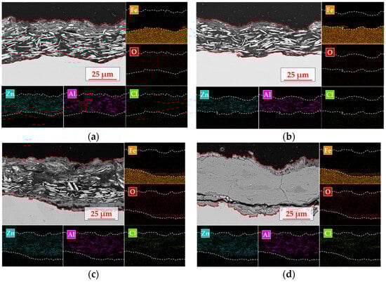
Figure 9.
Cross-sectional morphology and elemental distribution of the organic Zn14Al1.4 composite coatings in the simulated tropical marine atmospheric corrosion test: (a) cycle 1; (b) cycle 2; (c) cycle 4; and (d) cycle 6.
The organic Zn14Al1.4 composite coating itself exhibits the characteristic morphology of a lamellar zinc structure (plate-like Zn phase) compounded with the aluminum phase. In the initial corrosion stage (cycle 1, Figure 9a), EDS surface mapping shows a pronounced enrichment of oxygen on the sample surface, along with localized Cl accumulation in the top layer. At this point, the Zn phase preferentially undergoes anodic dissolution, while the Al phase exhibits typical passivation behavior; the formation of a dense Al2O3 passive film on the Al component retards further corrosion, establishing a “sacrificial anode and passivation synergistic” protection mode. As the test progresses into cycle 2 (Figure 9b), selective corrosion of the Zn phase not only generates microporous structures on the coating surface but also creates diffusion pathways for Cl− to penetrate deeper into the coating, causing the corrosion reaction to extend toward the coating/substrate interface. Cross-sectional analysis indicates that corrosion at the interface region remains dominated by preferential dissolution of the Zn phase, while the Al phase maintains its passivated protective state. Notably, Cl− has migrated along surface defects into the coating interior and formed a secondary enrichment peak at the interface, presaging the onset of corrosion medium-induced degradation of the interfacial bonding strength. By cycle 4 (Figure 9c), interface corrosion of the coating system intensifies markedly; EDS elemental mapping shows Cl enrichment in the mid-layer of the coating and the formation of penetration channels along Zn lamellae gaps, which induce accelerated Zn dissolution. Cl forms a continuous enrichment band in the middle layer of the coating, while macroscopic cracks and coating spallation appear at the interface region, indicating irreversible degradation of interfacial bonding strength, microcrack initiation at the interface, and consequent reduction in coating/substrate adhesion. At cycle 6 (Figure 9d), SEM cross-sectional morphology reveals structural failure of the coating system; EDS analysis shows a pronounced attenuation of Zn and Al signals, with the interface region completely overlaid by Fe-based oxides. At this stage, volumetric expansion stresses from accumulated corrosion products cause widespread coating spallation, exposing the substrate directly to the corrosive environment and marking the complete failure of the protective system. This corrosion evolution process reveals that, in a tropical marine atmospheric environment, the failure of the organic Zn14Al1.4 composite coating primarily follows a progressive mechanism of “preferential Zn dissolution → formation of Cl− diffusion channels → interfacial bonding strength decay → bulk coating spallation,” in which the migration and enrichment of Cl− within the coating are the critical factors accelerating interfacial failure.
3.4. Corrosion Products
The XPS analysis results of the organic Zn14Al1.4 composite coating after the second cycle of the simulated tropical marine atmospheric corrosion test, as shown in Figure 10, reveal the chemical composition evolution characteristics in the early stage of corrosion. The high-resolution Zn 2p spectrum (Figure 10a) shows a doublet at 1021.9 eV and 1022.71 eV, corresponding to the spin–orbit split Zn2+ 2p3/2 levels, while the characteristic peak at 1045.3 eV is assigned to the Zn2+ 2p1/2 level; the binding energy data indicate that ZnO and Zn(OH)2 are the predominant species on the coating surface. The Al 2p spectrum (Figure 10b) exhibits peaks at 71.3 eV and 73.8 eV, corresponding to the Al3+ chemical states in Al2O3 and Al(OH)3, respectively, confirming that the aluminum component has formed a composite oxide/hydroxide protective layer via passivation reactions. The O 1s spectrum (Figure 10c) is deconvoluted into peaks at 531.0 eV (lattice oxygen O2−) and 532.2 eV (hydroxyl OH−), indicating that the hydrolysis of metal oxides (ZnO + H2O → Zn(OH)2) dominates the surface chemical evolution. In the Cl 2p spectrum (Figure 10d), the doublet at 199.4 eV (2p3/2) and 200.79 eV (2p1/2) confirms that Cl− is chemically adsorbed and enriched on the coating surface; the observed binding energy shifts suggest the formation of coordination compounds between Cl− and Zn2+/Al3+. The C 1s spectrum (Figure 10e) is resolved into peaks at 284.8 eV (C-C), 286.5 eV (C-O/C-N), and 288.4 eV (CO32−), indicating that environmental CO2 participates in the formation of corrosion products via interfacial reactions (CO2 + 2OH− → CO32− + H2O).
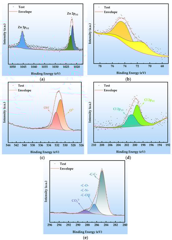
Figure 10.
XPS spectra at cycle 2 after the simulated tropical marine atmospheric corrosion test: (a) Zn 2p; (b) Al 2p; (c) O 1s; (d) Cl 2p; and (e) C 1s.
Comprehensive XPS analysis indicates that, in cycle 2, the corrosion products predominantly comprise zinc-based compounds (ZnO as a shielding phase, Zn(OH)2 as a transition phase, and the Cl−-intercalated layered double hydroxide Zn5(OH)8Cl2), aluminum-based passivation products (a dense Al2O3 passive film and Al(OH)3 hydrolysis product), and a composite layered double hydroxide structure containing CO32−/OH− (Zn6Al2(OH)16CO3). The synergistic formation of these species indicates that, in the early stage of corrosion, sacrificial anode protection by Zn and passivation by Al act in concert, while Cl− chemisorption and CO2 ingress lay the groundwork for subsequent coating failure.
The XPS analysis presented in Figure 11 reveals the chemical composition of the surface corrosion products and the failure mechanism of the organic Zn14Al1.4 composite coating after cycle 6. The corrosion layer is composed primarily of Zn, Al, O, Cl, and Fe, with the chemical states of Zn, Al, O, and Cl remaining consistent with those observed in cycle 2 (Figure 10): the Zn 2p spectrum (Figure 11a) is still dominated by Zn2+ 2p3/2 (1022.1 eV) and 2p1/2 (1045.5 eV) peaks, and the Al 2p spectrum (Figure 11b) shows Al in its oxidized state (71.5 eV, Al2O3), indicating that the fundamental corrosion pathways of Zn and Al have not changed. The C 1s spectrum (Figure 11e) exhibits a significant change: the characteristic peak at 286.5 eV (C-O/C-N) disappears entirely. This confirms that the organic resin matrix has undergone chemical chain scission (hydrolysis of C-O bonds) and physical delamination due to prolonged corrosion, resulting in the complete disintegration of the organic–metal composite structure. Deconvolution of the Fe 2p high-resolution spectrum (Figure 11f) further elucidates substrate corrosion: the main peaks at 709.15 eV and 722.8 eV correspond to Fe 2p3/2 and 2p1/2 orbitals, respectively, while the satellite peaks at 712.0 eV and 725.6 eV clearly indicate the presence of mixed-valence Fe2+/Fe3+ oxides. Binding energy matching indicates that the corrosion products include FeO, Fe2O3, Fe3O4, and FeOOH.
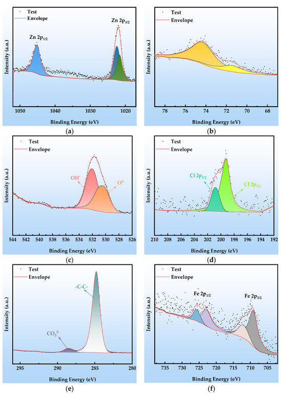
Figure 11.
XPS spectra at cycle 6 after the simulated tropical marine atmospheric corrosion test: (a) Zn 2p; (b) Al 2p; (c) O 1s; (d) Cl 2p; (e) C 1s; and (f) Fe 2p.
3.5. Electrochemical Properties
Figure 12 shows the Nyquist plots of the EIS of the organic Zn14Al1.4 composite coating at various exposure cycles in the simulated tropical marine atmospheric corrosion environment. Figure 13 presents the Bode plots of the EIS. Figure 14 illustrates the equivalent circuit models used to fit the EIS: pre-corrosion spectra are fitted with Figure 14a, cycle 1 with Figure 14b, cycles 2 and 4 with Figure 14c, and cycles 3, 5, and 6 with Figure 14d. The experimental data are displayed as discrete points, while the fitted equivalent circuit results are represented by continuous lines. Notably, the region labeled “Enlarge Area 1” in Figure 14a is shown in greater detail in Figure 14b; the “Enlarge Area 2” region in Figure 14b is further magnified in Figure 14c; and the “Enlarge Area 3” in Figure 14c is subsequently enlarged in Figure 14d.
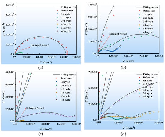
Figure 12.
Nyquist plots of the organic Zn14Al1.4 composite coatings in the simulated tropical marine atmospheric corrosion test: (a) general; (b) enlarged area 1; (c) enlarged area 2; and (d) enlarged area 3.
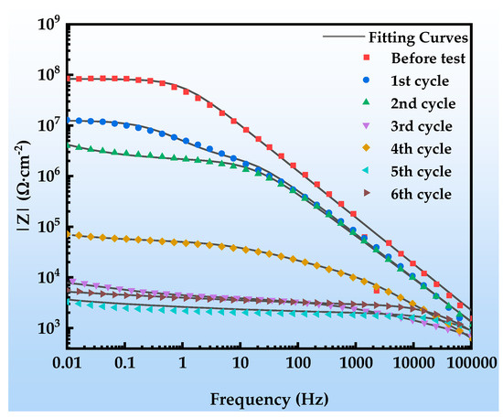
Figure 13.
Bode plot of the organic Zn14Al1.4 composite coatings in the simulated tropical marine atmospheric corrosion test.
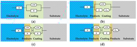
Figure 14.
Equivalent circuit model used for EIS fitting of the organic Zn14Al1.4 composite coatings in the simulated tropical marine atmospheric corrosion test. (a) used for untested; (b) used for 1 cycle; (c) used for 2 and 4 cycles; and (d) used for 3, 5, and 6 cycles.
The Nyquist spectra in Figure 12 reveal the electrochemical behavior of the organic Zn14Al1.4 composite coating under the simulated tropical marine atmospheric corrosion environment. Prior to corrosion testing, the sample exhibits a single time constant. As the corrosion test progresses, the radius of the capacitive arc gradually decreases, which is attributed to Cl−/H2O penetrating the coating through micro-defects, causing swelling or chemical degradation of the coating. In the low-frequency region of cycle 1, a Warburg impedance appears, indicating accumulation of Zn2+ corrosion products at the interface, the formation of a diffusion layer, and a shift to diffusion-controlled corrosion [44]. From cycle 2 onward, a new capacitive arc emerges in the low-frequency region, corresponding to the formation of an Al2O3 passive film on the Al substrate; the film’s parallel resistance and capacitance structure indicates its inhibitory effect on short-term corrosion. Overall, the coating undergoes a chain failure pathway of “sacrificial anode protection → passivation film formation → substrate corrosion,” with its protective performance progressively diminishing over the corrosion cycles.
Figure 13 depicts the evolution of the Bode spectra of the organic Zn14Al1.4 composite coating at different exposure cycles in the simulated tropical marine atmospheric corrosion environment. The low-frequency impedance modulus (|Z|0.01Hz) decreases monotonically during the first two corrosion cycles; despite early coating degradation, it still provides effective substrate protection. The anomalous impedance drops in cycle 3 may be related to rapid diffusion channels formed by corrosive ions (Cl−, H2O, etc.) penetrating defects in the coating. The impedance recovery observed in cycle 4 is associated with the accumulation of interfacial corrosion products (primarily FeOOH, Zn5(OH)8Cl2·H2O, AlOOH, etc.), whose passive layer can temporarily impede charge transfer. Although similar fluctuations occur in subsequent cycles, the overall impedance remains below 105 Ω·cm−2, confirming that the coating has completely lost its long-term protective capability.
Table 4 lists the fitted parameters of the EIS equivalent circuits. In the initial exposure stage (cycles 0~4), the coating capacitance (Yc) increases significantly, attributed to swelling induced by water ingress and hydration of hydrophilic groups in the organic resin matrix during corrosion testing [45]. Concurrently, the CPE exponent n1 decreases, indicating reduced interfacial homogeneity, primarily due to the heterogeneous nucleation of initial corrosion products on the metal substrate. In the mid-corrosion stage (cycles 4~6), Yc shows an anomalous decrease while n1 rises, revealing an interfacial repair mechanism whereby corrosion products progressively fill coating pores to form a dense corrosion-product layer. However, the coating resistance (Rc) continues to decrease during this stage, confirming that Cl− infiltration forms conductive pathways in the coating [46], accelerating the coating’s aging and corrosion process.
Table 4.
Parameters of the equivalent circuit fitting for the organic Zn14Al1.4 composite coatings in the simulated tropical marine atmospheric corrosion test.
The evolution of the double-layer parameters shows that Ydl increases by two orders of magnitude between cycles 2~6, accompanied by a decrease in n2 and a significant reduction in charge-transfer resistance (Rct). This indicates that corrosive media diffuse to the substrate, initiating anodic dissolution, which increases defect density at the corrosion product/substrate interface, intensifies local micro-cell effects, and increases interface roughness. Notably, coating spallation occurs during cycles 5~6, and SEM-EDS and XPS confirm the accumulation of Fe-based corrosion products at the interface.
Analysis of the evolving equivalent circuits of the EIS data indicates that, during exposure to the tropical marine atmosphere, the coating/metal interface undergoes three distinct stages: an intact coating–substrate interface structure; a three-phase interface formed by the coating, corrosion nuclei, and substrate, induced by nucleation of corrosion products; and a composite interface of the coating, corrosion layer, and substrate resulting from corrosion product accumulation. This evolution process aligns with the coating’s chain failure pathway and the observed variations in the fitted equivalent circuit parameters.
4. Corrosion Mechanism of the Organic Zn14Al1.4 Composite Coating
Figure 15 is a schematic diagram of the corrosion mechanism of the organic Zn14Al1.4 composite coating. The evolution of the corrosion mechanism of the organic Zn14Al1.4 composite coating in a simulated marine environment can be divided into four stages: (1) the incubation accumulation period (cycle 1), during which corrosion is limited by initial Zn anodic dissolution, passive film protection, and oxygen diffusion kinetic barriers, proceeding slowly as localized micro-cell corrosion; (2) the accelerated expansion period (cycle 2), when passive film rupture induces Cl−/H2O penetration to the interface and complex Zn-Al corrosion products evolve; (3) the substrate corrosion nucleation period (cycles 3~4), in which corrosive media diffuse to the metal substrate that serves as the anode, leading to Fe2+ oxidation and hydrolysis to form corrosion products whose volumetric expansion stresses cause blistering and delamination of the coating; and (4) the unstable corrosion outbreak period (cycles 5~6), when accumulation of corrosion products forms ion-selective channels, triggering interfacial acidification and local occluded-cell corrosion [41,47], with substrate iron directly participating and entering a thermodynamically irreversible unstable stage.
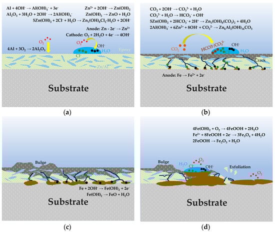
Figure 15.
Schematic illustration of the corrosion mechanism of the organic Zn14Al1.4 composite coating in the simulated tropical marine atmospheric test. (a) incubation accumulation stage; (b) accelerated expansion period; (c) substrate corrosion nucleation period; and (d) unstable corrosion outbreak period.
In the incubation accumulation stage, as shown in Figure 15a, localized electrochemical corrosion appears on the coating surface, reflecting the Zn-dominated sacrificial anode protection mechanism assisted by an Al-rich passive film inhibition effect. The Zn-rich phase, acting as the anode, is attacked first, undergoing Zn anodic dissolution (Formula (3)) to generate Zn2+. Correspondingly, dissolved oxygen in the coating surface electrolyte is reduced at cathodic sites (Formula (4)), producing OH− [48]. Additionally, the Al-rich phase within the coating oxidizes to form a dense Al2O3 passive film (Formula (5)), providing a degree of passivation protection. With the accumulation of Zn2+ and OH−, Zn(OH)2 precipitates on the coating surface (Formula (6)); this Zn(OH)2 layer both fills local depressions to slow electrolyte ingress and, due to its porous structure, gradually provides ion transport pathways for subsequent corrosion reactions [13]. Chloride ions (Cl−) migrate to anodic sites, partially dissolving and reorganizing Zn(OH)2 to form Zn5(OH)8Cl2·H2O corrosion products (Formula (7)) [49], commonly observed in marine corrosion systems and capable of temporarily covering the coating surface.
Anode: Zn → Zn2+ + 2e−
Cathode: O2 + 2H2O + 4e− → 4OH−
4Al + 3O2 → 2Al2O3
Zn2+ +2OH− → Zn(OH)2
5Zn(OH)2 + 2Cl− + H2O → Zn5(OH)8Cl2·H2O + 2OH−
As corrosion continues, it enters the accelerated expansion period, as shown in Figure 15b, where corrosion products accumulate on the coating surface and undergo complex transformations. Environmental CO2 participates in these transformations (Formulas (8) and (9)), introducing carbonate ions that produce Zn5(OH)6(CO3)2 corrosion products (Formula (10)), thereby promoting the evolution of Zn corrosion products into carbonate compounds [49]. These coating layers have a degree of passivation and self-healing effect, slowing further Zn dissolution. However, the Al passive film loses stability at higher pH and may dissolve from the oxide layer, making Al dissolution possible (Formulas (11) and (12)) [50]. Dissolved Al(OH)4− combines with Zn2+ and OH− to form a LDH structure (Formula (13)) [50]. The resulting Zn-Al LDH corrosion product layer typically has a layered structure [13] that can further seal the surface and improve the coating’s corrosion resistance.
CO2 + 2OH− → CO32− + H2O
CO32− + H2O → HCO3− + OH−
5Zn(OH)2 + 2HCO3− + 2H+ → Zn5(OH)6(CO3)2 + 4H2O
Al + 4OH− → Al(OH)4− + 3e−
Al2O3 + 3H2O + 2OH− → 2Al(OH)4−
2Al(OH)4− + 6Zn2+ + 8OH− + CO32− → Zn6Al2(OH)16CO3
In the substrate corrosion nucleation period, as shown in Figure 15c, the coating’s barrier effect weakens, and after further penetration of corrosive media, the steel substrate begins to participate in corrosion reactions. Iron, acting as the anode, dissolves (Formula (14)) to produce Fe2+, which rapidly hydrolyzes to form Fe(OH)2 (Formula (15)) [51]. The significant volumetric expansion of these iron corrosion products generates internal stresses [52], causing blistering and delamination at the coating/substrate interface, breaking adhesion and accelerating corrosion-induced failure. Subsequently, in the presence of oxygen, Fe(OH)2 is oxidized to form FeOOH and magnetite Fe3O4 (Formulas (16) and (17)) [53].
Anode: Fe → Fe2+ + 2e−
Fe + 2OH− → Fe(OH)2 + 2e−
4Fe(OH)2 + O2 → 4FeOOH + 2H2O
Fe2+ + 8FeOOH + 2e− → 3Fe3O4 + 4H2O
In the unstable corrosion outbreak period (cycle 6), as shown in Figure 15d, the corrosion product layer thickens further and forms porous channels, creating ion-selective transport pathways; continuous Fe2+ release fills layer voids with acidic FeCl2 solution [41,47], markedly intensifying local corrosion. Under highly acidic conditions, the existing Fe(OH)2 corrosion product undergoes further dehydration decomposition to form FeO and Fe2O3 (Formulas (18) and (19)) [54]. In this stage, the occluded cell effect intensifies significantly, driving the corrosion reaction into a thermodynamically irreversible unstable state and causing complete loss of the coating’s protective function.
Fe(OH)2 → FeO + H2O
2FeOOH → Fe2O3 + H2O
5. Conclusions
- (1)
- In the simulated marine environment, the organic Zn14Al1.4 composite coating’s early corrosion products are dominated by Zn(OH)2: in the mid-stage, Zn5(OH)8Cl2·H2O, Zn5(OH)6(CO3)2, and other Zn-hydroxide derivatives form alongside Al2O3/Al(OH)3 passive phases and Zn6Al2(OH)16CO3; and in the late stage, Fe-based products such as FeO, Fe2O3, Fe3O4, and FeOOH predominate, resulting in a complex, multilayered interface.
- (2)
- The coating is dense and intact initially, but by cycle 6 exhibits a porous, honeycomb-like structure with Cl and O enrichment in cracks and pores, increasing the porosity of the product layer.
- (3)
- The corrosion mechanism evolution of the organic Zn14Al1.4 composite coating in the simulated marine environment occurs in four stages: incubation accumulation, accelerated expansion, substrate corrosion nucleation, and unstable corrosion outbreak.
- (4)
- The failure of the organic Zn14Al1.4 composite coating is driven by a combination of anodic metal dissolution, volumetric effects of corrosion products, electrochemical micro-cell action, and interfacial physicochemical instability, providing a comprehensive kinetic framework for coating life assessment and failure prediction.
Author Contributions
Conceptualization, H.Z. and K.X.; Methodology, H.Z. and H.Y.; Validation, H.Z. and H.Y.; Formal Analysis, H.Y.; Investigation, C.L., Y.H., H.W. and P.Y.; Resources, K.X. and J.G.; Data Curation, H.Z. and H.Y.; Writing—Original Draft Preparation, H.Z.; Writing—Review and Editing, K.X. and H.Y.; Visualization, H.Z.; Supervision, K.X.; Project Administration, K.X.; Funding Acquisition, K.X. All authors have read and agreed to the published version of the manuscript.
Funding
This work was supported by the Science and Technology project of the State Grid Corporation of China (Research on Corrosion Resistance Enhancement and Environmental Performance Evaluation Technology for Steel Structural Supports in Substations, 5200-202355145A-1-1-ZN).
Institutional Review Board Statement
Not applicable.
Informed Consent Statement
Not applicable.
Data Availability Statement
Data are contained within the article.
Conflicts of Interest
Author Chang Liu was employed by the Sate Grid Beijing Electric Power Company. Author Yesheng Huang and Haoyu Wu were employed by the Beijing Electric Power Economic Research Institute Co., Ltd. Author Pan Yi was employed by the China Electric Power Research Institute. The remaining authors declare that the research was conducted in the absence of any commercial or financial relationships that could be construed as a potential conflict of interest.
References
- Hu, Q.; Yang, S.; Zhang, W.; Da, G.; Xu, X.; Wang, X. Corrosion failure analysis of engineering structural steels in tropical marine atmospheres: A comparative study of ordinary and new weathering steels. Eng. Fail. Anal. 2024, 156, 107830. [Google Scholar] [CrossRef]
- Li, X.; Zhang, D.; Liu, Z.; Li, Z.; Du, C.; Dong, C. Materials science: Share corrosion data. Nature 2015, 527, 441–442. [Google Scholar] [CrossRef] [PubMed]
- Chen, J.H.; Song, J.L.; Hu, W.; Zhu, T.Y.; Gao, J.; Xiao, K. Corrosion Behaviour of Polyurethane Coating Containing Flurocarbon on Carbon Steel in Tropical Marine Atmospheric Environment. Int. J. Electrochem. Sci. 2022, 17, 221160. [Google Scholar] [CrossRef]
- Jiang, Z.; Chen, T.; Che, Z.; Liu, C.; Yan, Y.; Huang, F.; Cheng, X.; Li, X. Effect of Ca-Mg microalloying on corrosion behavior and corrosion resistance of low alloy steel in the marine atmospheric environment. Corros. Sci. 2024, 234, 112134. [Google Scholar] [CrossRef]
- Dong, B.; Liu, W.; Zhang, T.; Chen, L.; Fan, Y.; Zhao, Y.; Li, H.; Yang, W.; Sun, Y. Clarifying the effect of a small amount of Cr content on the corrosion of Ni-Mo steel in tropical marine atmospheric environment. Corros. Sci. 2023, 210, 110813. [Google Scholar] [CrossRef]
- Dong, B.; Liu, W.; Chen, L.; Zhang, T.; Fan, Y.; Zhao, Y.; Li, H.; Yang, W.; Sun, Y. Unraveling the effect of chloride ion on the corrosion product film of Cr-Ni- containing steel in tropical marine atmospheric environment. Corros. Sci. 2022, 209, 110741. [Google Scholar] [CrossRef]
- Zhu, Q.; Zhang, B.; Zheng, M.; Zhao, X.; Xu, J. Corrosion Behaviors of S355 Steel under Simulated Tropical Marine Atmosphere Conditions. J. Mater. Eng. Perform. 2022, 31, 10054–10062. [Google Scholar] [CrossRef]
- Luo, L.; Wang, B.; Zhou, J.; Liu, J.; Wang, X. Effect of Cyclic Stress on Corrosion Behavior of 7A09 Aluminum Alloy in Tropical Coastal Atmosphere. Int. J. Electrochem. Sci. 2022, 17, 221215. [Google Scholar] [CrossRef]
- Sun, Y.; Liu, W.; Chen, L.; Li, H.; Zhang, B.; Wang, F.; Hou, B. Establishing chloride concentration range for protective rust formation on weathering steel in simulated tropical marine atmospheres. Corros. Eng. Sci. Technol. 2024. [Google Scholar] [CrossRef]
- Lin, H.; Wang, Y. An organic phosphonic acid doped polyaniline/zirconia/epoxy composite coating for metal protection in the marine environment. Prog. Org. Coat. 2023, 182, 107671. [Google Scholar] [CrossRef]
- Huang, H.; Hou, L.; Du, H.; Wei, H.; Liu, X.; Wang, Q.; Wei, Y. Efficient dual defense: PDA-Cu coating for simultaneous corrosion resistance and antibacterial protection of Mg alloys. Corros. Sci. 2024, 233, 112103. [Google Scholar] [CrossRef]
- Yang, Y.; Sun, Y.; Su, L.; Deng, P.; Zhang, Y.; Liu, J.; Fang, X. Structure and Properties of ZnAl-ER Composite Coating Prepared by Spraying. J. Chin. Soc. Rare Earths 2024, 42, 528–536. [Google Scholar]
- Zhang, J.; Zhu, Q.; Wang, Z.; Wang, X.; Yan, J. Flake-like ZnAl alloy powder modified waterborne epoxy coatings with enhanced corrosion resistance. Prog. Org. Coat. 2023, 175, 107367. [Google Scholar] [CrossRef]
- Yang, Y.; Chen, Y.; Jiang, N.; Wang, Y.; Yang, L.; Fang, X.; Liu, J. Preparation and Properties of ZnAl-EP Coating for Bonded NdFeB with High Corrosion Resistance. J. Chin. Soc. Rare Earths 2023, 41, 748–756. [Google Scholar]
- Zubielewicz, M.; Langer, E.; Królikowska, A.; Komorowski, L.; Wanner, M.; Krawczyk, K.; Aktas, L.; Hilt, M. Concepts of steel protection by coatings with a reduced content of zinc pigments. Prog. Org. Coat. 2021, 161, 106471. [Google Scholar] [CrossRef]
- Zhang, J.; Luo, L.; Zhu, Q.; wang, Z. The unique flake ZnAl alloy and OIT anti-corrosion and anti-mildew waterborne epoxy coatings. Inorg. Chem. Commun. 2023, 156, 111120. [Google Scholar] [CrossRef]
- Ding, Y.; Zhang, F.; Zhou, H.; Cheng, S.; Xu, K.; Wang, Z.; Xie, S.; Tian, J. Effect of Al Content on the Long-Term Corrosion Behavior of Arc-Sprayed ZnAl Alloy Coatings. Coatings 2023, 13, 1720. [Google Scholar] [CrossRef]
- Bobzin, K.; Öte, M.; Knoch, M.A. Designing the corrosion products of ZnAl15: A new approach to smart corrosion protection coatings? Corros. Sci. 2019, 155, 217–229. [Google Scholar] [CrossRef]
- Yuan, Z.Y.; Wang, Y.B.; Zou, R.; Yang, Y.C.; Toyohisa, F.; Wei, Y.Z. Effect of LDHs on Corrosion Behavior of 6061Al Alloy in NaCl Solution with Different Dissolved Oxygen Contents. Rare Met. Mater. Eng. 2022, 51, 1589–1596. [Google Scholar]
- Amanian, S.; Naderi, R.; Mahdavian, M. The Role of an In-Situ Grown Zn-Al Layered Double Hydroxide Conversion Coating in the Protective Properties of Epoxy Coating on Galvanized Steel. J. Electrochem. Soc. 2022, 169, 031511. [Google Scholar] [CrossRef]
- Huang, Q.; Wang, Y.; Zhou, B.; Wei, Y.; Gao, F.; Fujita, T. The effect of ZnAl-LDHs-CO3 on the corrosion behaviour of Zn-5Al alloys in 3.5wt.% NaCl solution. Corros. Sci. 2021, 179, 109165. [Google Scholar] [CrossRef]
- Holzner, T.; Luckeneder, G.; Strauß, B.; Valtiner, M. Environmentally Friendly Layered Double Hydroxide Conversion Layers: Formation Kinetics on Zn–Al–Mg-Coated Steel. ACS Appl. Mater. Interfaces 2022, 14, 6109–6119. [Google Scholar] [CrossRef] [PubMed]
- Yang, Y.; Jiang, N.; Sun, Y.; Yang, L.; Guan, C.; Zhang, E.; Fang, X.; Liu, J. Structure and Corrosion Resistance Characteristics of ZnAl/EP Coating on Bonded NdFeB Magnet. J. Mater. Eng. Perform. 2023, 32, 5475–5482. [Google Scholar] [CrossRef]
- Zhang, H.; Sun, W.; Wang, L.; Feng, Y.; Ma, S.; Zhao, L.; Liu, G. Nano-structure and hydrophobicity co-determined barrier properties of corrosion protective ZnAl-LDH film in atmospheric environment. Corros. Sci. 2024, 232, 112052. [Google Scholar] [CrossRef]
- Liu, Q.L.; Wang, X.D.; Wang, X.K.; Yan, X.W.; Ma, X.J. Study of high emittance chemical conversion coatings for magnesium alloys. Surf. Eng. 2014, 30, 48–52. [Google Scholar] [CrossRef]
- De Rosa, L.; Mitton, D.B.; Monetta, T.; Bellucci, F.; Springer, J. Degradation of zinc oxide thin films in aqueous environment:. Part II—Coated Films. Mater. Corros. 2001, 52, 931–935. [Google Scholar] [CrossRef]
- Liu, Z.; Yan, D.; Dong, Y.; Yang, Y.; Chu, Z.; Zhang, Z. The effect of modified epoxy sealing on the electrochemical corrosion behaviour of reactive plasma-sprayed TiN coatings. Corros. Sci. 2013, 75, 220–227. [Google Scholar] [CrossRef]
- Zhicheng, L.; Dejun, K. Microstructure, corrosive–wear and immersion corrosion performances of laser cladded FeCoNiCr–Mo (Al, Ti) high–entropy alloy coatings. Corros. Sci. 2024, 227, 111766. [Google Scholar] [CrossRef]
- Zhang, Y.; Sun, Y.; Fan, X.; Liao, B.; Deng, C.; Li, S.; Wang, C.; Xv, Y.; Li, K.; Lv, Y. Corrosion behavior of WC-NiMoCrFeCo coating in seawater environment: Positive corrosion inhibition of a novel dynamic reaction product. Chem. Eng. J. 2025, 507, 160568. [Google Scholar] [CrossRef]
- Yao, W.; Wu, L.; Jiang, B.; Pan, F. Slippery liquid-infused porous surface by ZnAl-layered double hydroxide on AZ31 Mg alloys. J. Taiwan Inst. Chem. Eng. 2023, 150, 105017. [Google Scholar] [CrossRef]
- Wang, J.; Wang, Z.; Yan, N.; Han, Z.; Chang, Y.; Wang, J.; Li, Q. Clarifying the chemical reactions of the weakening of adhesion between epoxy resin and aluminum by molecular dynamic simulation and experiment. Front. Mater. 2022, 9, 985758. [Google Scholar] [CrossRef]
- Moosburger-Will, J.; Greisel, M.; Horn, S. Physical aging of partially crosslinked RTM6 epoxy resin. J. Appl. Polym. Sci. 2014, 131, 41121. [Google Scholar] [CrossRef]
- Gibhardt, D.; Buggisch, C.; Meyer, D.; Fiedler, B. Hygrothermal Aging History of Amine-Epoxy Resins: Effects on Thermo-Mechanical Properties. Front. Mater. 2022, 9, 826076. [Google Scholar] [CrossRef]
- Zhao, M.; Wu, S.; An, P.; Luo, J. Study on the deterioration process of a chromium-free conversion coating on AZ91D magnesium alloy in NaCl solution. Appl. Surf. Sci. 2006, 253, 468–475. [Google Scholar] [CrossRef]
- Li, M.C.; Jiang, L.L.; Zhang, W.Q.; Qian, Y.H.; Luo, S.Z.; Shen, J.N. Electrochemical corrosion behavior of nanocrystalline zinc coatings in 3.5% NaCl solutions. J. Solid State Electrochem. 2007, 11, 1319–1325. [Google Scholar] [CrossRef]
- Persson, D.; Thierry, D.; LeBozec, N. Corrosion product formation on Zn55Al coated steel upon exposure in a marine atmosphere. Corros. Sci. 2011, 53, 720–726. [Google Scholar] [CrossRef]
- Wang, Y.; Reng, X.; Wang, D.; Liu, H.; Wu, Y. Minimizing Color Difference in AAO-Based Coatings for Urban Camouflage. Nanomaterials 2025, 15, 890. [Google Scholar] [CrossRef]
- Hayden, S.C.; Chisholm, C.; Eichmann, S.L.; Grudt, R.; Frankel, G.S.; Hanna, B.; Headrick, T.; Jungjohann, K.L. Genesis of Nanogalvanic Corrosion Revealed in Pearlitic Steel. Nano Lett. 2022, 22, 7087–7093. [Google Scholar] [CrossRef]
- Laleh, M.; Jurak, T.; Gusieva, K.; Williams, J.; Renshaw, W.; Correnti, S.; Hodges, J.; Gazder, A.A. New insights into corrosion initiation and propagation in a hot-dip Al-Zn-Mg-Si alloy coating via multiscale analytical microscopy. Corros. Sci. 2025, 245, 112695. [Google Scholar] [CrossRef]
- Behera, P.K.; Misra, S.; Mondal, K. Corrosion of Strained Plain Rebar in Chloride-Contaminated Mortar and Novel Approach to Estimate the Corrosion Amount from Rust Characterization. J. Mater. Civ. Eng. 2021, 33, 04021283. [Google Scholar] [CrossRef]
- Luo, Z.; Zuo, J.; Jiang, H.; Geng, W.; Zhou, Y.; Lian, Z.; Wei, W. Inhibition Effect of Fluoride Ion on Corrosion of 304 Stainless Steel in Occluded Cell Corrosion Stage in the Presence of Chloride Ion. Metals 2021, 11, 350. [Google Scholar] [CrossRef]
- Sun, B.-W.; Yang, J.-Y.; Dai, J.-W.; Zhao, Y.-B.; Zhang, L.; Huang, Z.-J.; Bai, J.; Xue, F.; Chu, P.K.; Chu, C.-L. Effects of PHB and PLA coatings on the corrosion behavior of ultrathin Mg sheets in artificial blood plasma containing BSA. Rare Met. 2025, 44, 5656–5671. [Google Scholar] [CrossRef]
- Fang, G.; Ding, W.; Liu, Y.; Zhang, J.; Xing, F.; Dong, B. Identification of corrosion products and 3D distribution in reinforced concrete using X-ray micro computed tomography. Constr. Build. Mater. 2019, 207, 304–315. [Google Scholar] [CrossRef]
- Deyab, M.A.; Mohamed, N.H.; Moustafa, Y.M. Corrosion protection of petroleum pipelines in NaCl solution by microcrystalline waxes from waste materials: Electrochemical studies. Corros. Sci. 2017, 122, 74–79. [Google Scholar] [CrossRef]
- Beraldo, C.H.M.; Spinelli, A.; Scharnagl, N.; da Conceição, T.F. New relations between modification degree, swelling and impedance in anticorrosion chitosan-derivative coatings on magnesium alloy AZ31. Carbohydr. Polym. 2022, 292, 119617. [Google Scholar] [CrossRef] [PubMed]
- Abdikheibari, S.; Parvizi, R.; Moayed, M.H.; Zebarjad, S.M.; Sajjadi, S.A. Beeswax-Colophony Blend: A Novel Green Organic Coating for Protection of Steel Drinking Water Storage Tanks. Metals 2015, 5, 1645–1664. [Google Scholar] [CrossRef]
- Kaji, T.; Sekiai, T.; Muto, I.; Sugawara, Y.; Hara, N. Visualization of pH and pCl Distributions: Initiation and Propagation Criteria for Crevice Corrosion of Stainless Steel. J. Electrochem. Soc. 2012, 159, C289. [Google Scholar] [CrossRef]
- Yang, Y.; Wang, Y.; Huang, Q.; Zhao, J.; Gao, F.; Wei, Y. Effect of ZnAl-LDH on corrosion resistance of Zn–55Al alloy in NaCl solution. Mater. Corros. 2023, 74, 1439–1455. [Google Scholar] [CrossRef]
- Mouanga, M.; Berçot, P.; Rauch, J.Y. Comparison of corrosion behaviour of zinc in NaCl and in NaOH solutions. Part I: Corrosion layer characterization. Corros. Sci. 2010, 52, 3984–3992. [Google Scholar] [CrossRef]
- Salgueiro Azevedo, M.; Allély, C.; Ogle, K.; Volovitch, P. Corrosion mechanisms of Zn(Mg, Al) coated steel in accelerated tests and natural exposure: 1. The role of electrolyte composition in the nature of corrosion products and relative corrosion rate. Corros. Sci. 2015, 90, 472–481. [Google Scholar] [CrossRef]
- Zhang, X.; Xiao, K.; Dong, C.; Wu, J.; Li, X.; Huang, Y. In situ Raman spectroscopy study of corrosion products on the surface of carbon steel in solution containing Cl− and SO42. Eng. Fail. Anal. 2011, 18, 1981–1989. [Google Scholar] [CrossRef]
- Zubielewicz, M.; Królikowska, A. The influence of ageing of epoxy coatings on adhesion of polyurethane topcoats and protective properties of coating systems. Prog. Org. Coat. 2009, 66, 129–136. [Google Scholar] [CrossRef]
- Su, G.; Yu, C.; Zheng, H.; Gao, X.; Xie, H.; Huo, M.; Wu, H.; Xu, J.; Du, L.; Jiang, Z. The Wet–Dry Cycling Corrosion Behavior of Low-Carbon Medium Manganese Steel Exposed to a 3.5% NaCl Solution Environment. J. Mater. Eng. Perform. 2022, 31, 7856–7869. [Google Scholar] [CrossRef]
- Xiao, K.; Dong, C.-f.; Li, X.-g.; Wang, F.-m. Corrosion products and formation mechanism during initial stage of atmospheric corrosion of carbon steel. J. Iron Steel Res. Int. 2008, 15, 42–48. [Google Scholar] [CrossRef]


Disclaimer/Publisher’s Note: The statements, opinions and data contained in all publications are solely those of the individual author(s) and contributor(s) and not of MDPI and/or the editor(s). MDPI and/or the editor(s) disclaim responsibility for any injury to people or property resulting from any ideas, methods, instructions or products referred to in the content. |
© 2025 by the authors. Licensee MDPI, Basel, Switzerland. This article is an open access article distributed under the terms and conditions of the Creative Commons Attribution (CC BY) license (https://creativecommons.org/licenses/by/4.0/).