The Influence of Interface Characteristics on the Adhesion/Cohesion of Plasma Sprayed Tungsten Coatings

Abstract
:1. Introduction
- Ability to coat large-area components, including non-planar shapes, with significant thickness
- A single-step manufacturing technology, without the need for further joining
- Possibility of in-situ repair of damaged parts
- Easy formation of graded composites
- Moderate heat input to the coated parts
- High strain tolerance
2. Experimental Section

| Notation | Surface treatment | Interlayer | Roughness Ra (μm) |
|---|---|---|---|
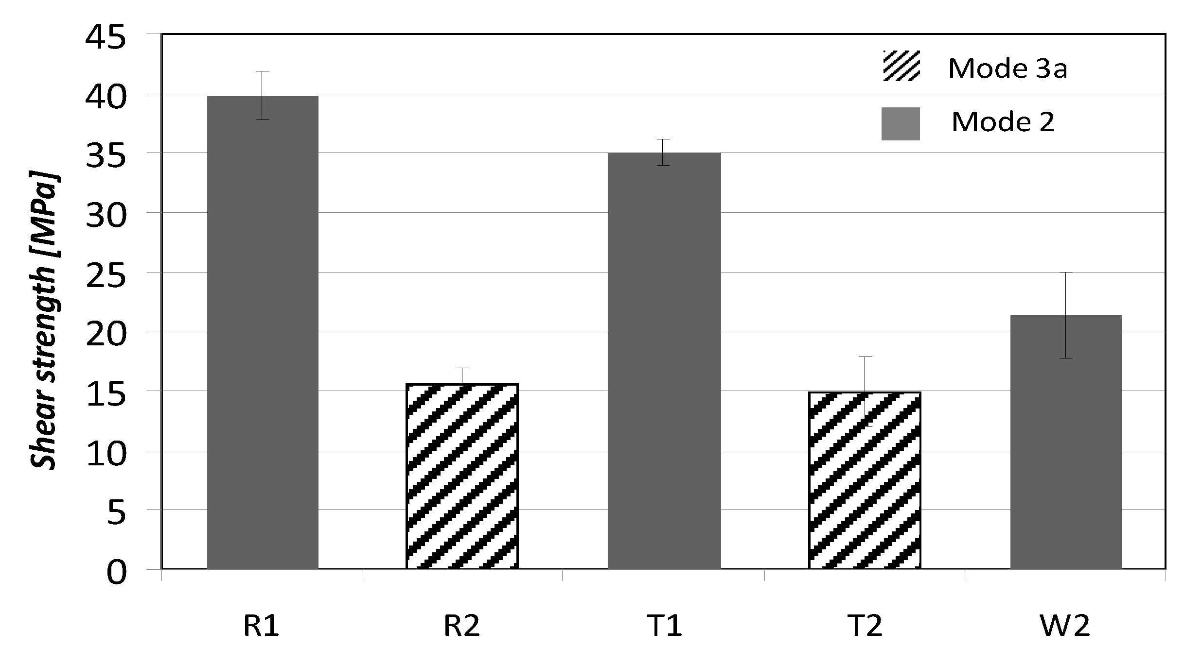
| R1 | grit-blasted, coarse | - | 7.8 ± 0.4 |
| R2 | grit-blasted, fine | - | 5.4 ± 0.2 |
| T1 | as-machined | Ti | 1.7 ± 0.2 |
| T2 | grit-blasted, fine | Ti | 6.0 ± 0.6 |
| W1 | as-machined | W | 1.6 ± 0.1 |
| W2 | grit-blasted, fine | W | 5.6 ± 0.6 |
| Parameter | Ti | W |
|---|---|---|
| Chamber preheat (°C) | 400 | 250 |
| Process pressure (mbar) | 2 × 10⁻³ | 2 × 10⁻³ |
| Deposition time (h) | 3 | 3 |
| Ar flow rate (sccm) | 95 | 90 |
| Cathode power (kW) | 2 × 4 | 1 × 4 |
| Bias (V) | 75 | 85 |
| UBM coils current (A) | 3 | 4 |
| Coating thickness (μm) | 2 | 1.5 |
3. Results and Discussion
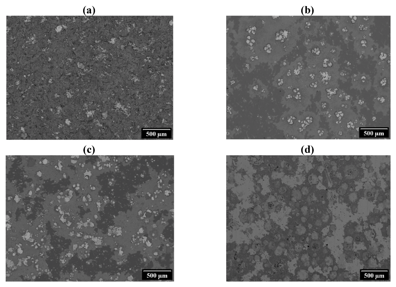
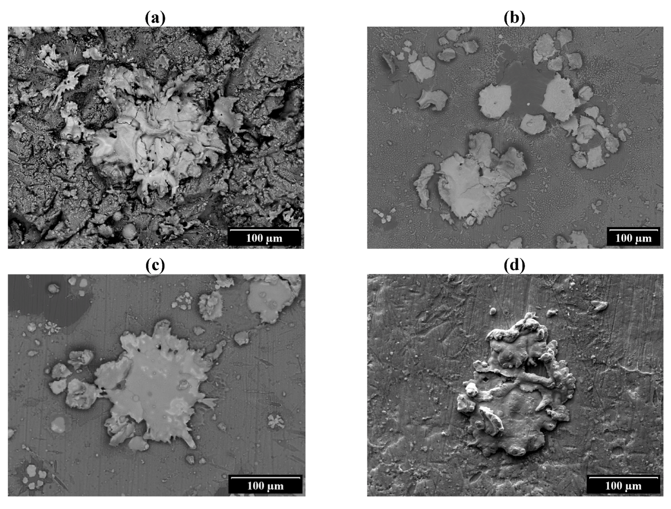
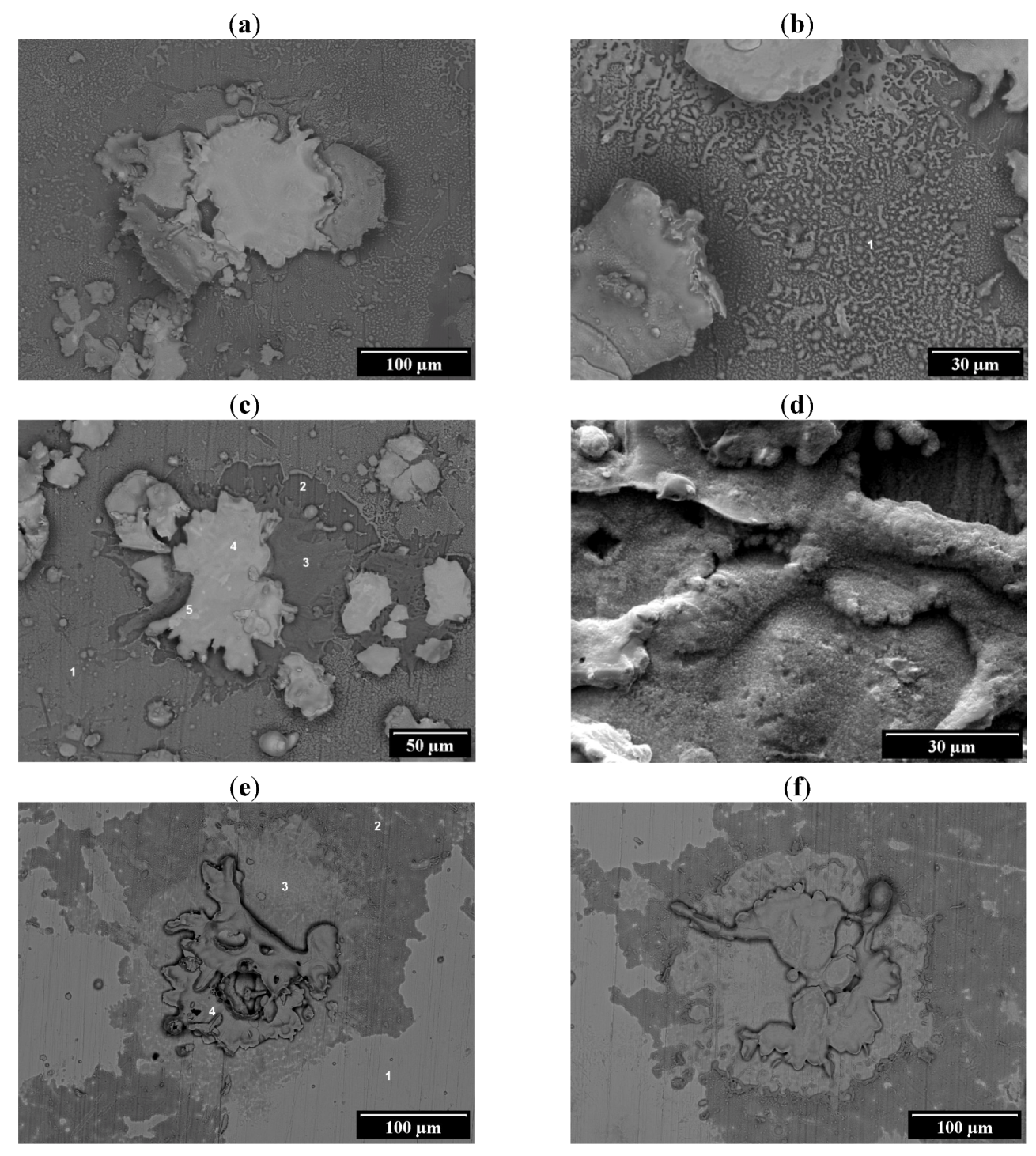
3.1. Observations of Single Splats


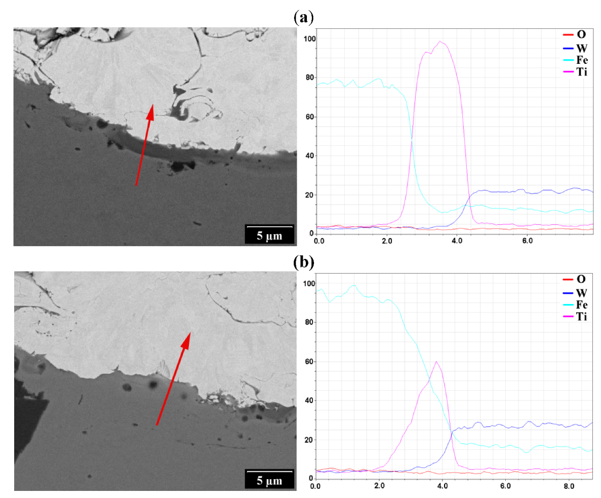
| Location | Feature | O | Ti | Fe | W |
|---|---|---|---|---|---|
| Ti-coated polished steel | |||||
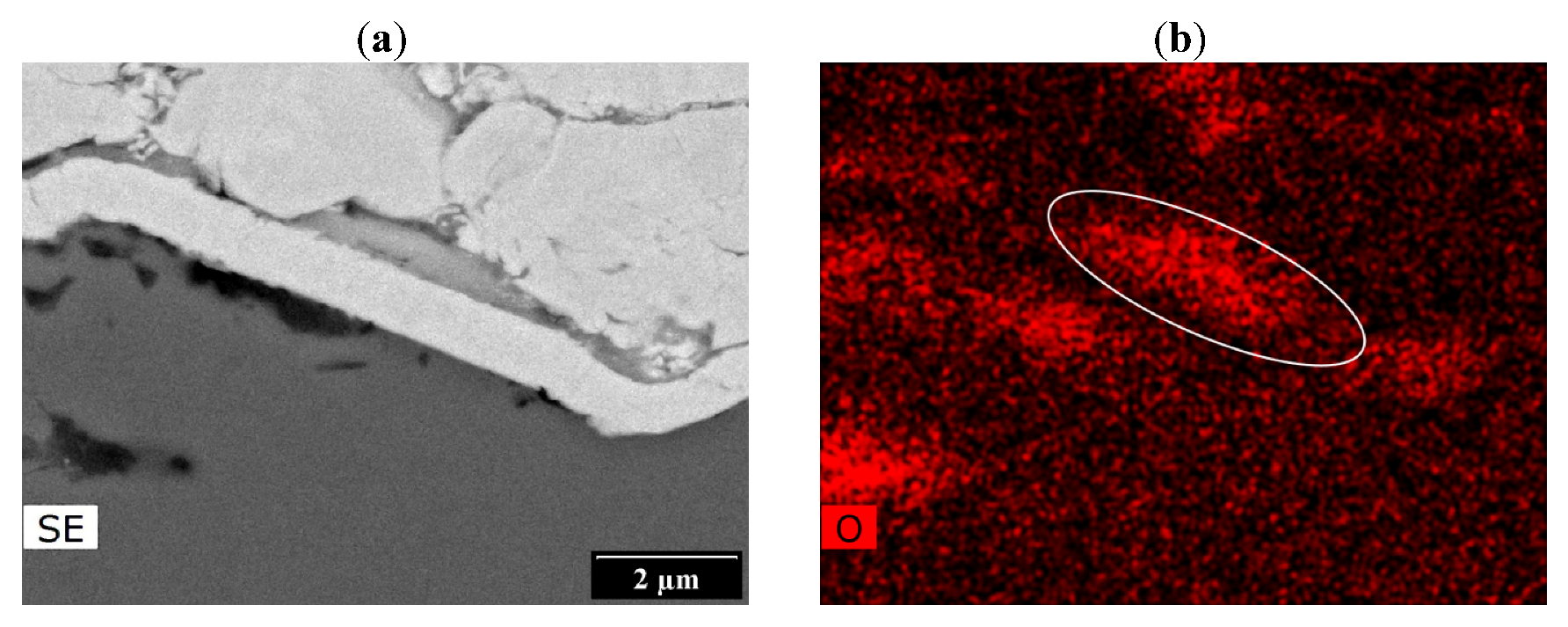
| Figure 3c-1 | substrate with WO3 deposit near splat | 24.9 | 43.8 | 2.2 | 29.1 |
| Figure 3c-2 | substrate near recoiled splat | 20.5 | 67.4 | 2.0 | 10.1 |
| Figure 3c-3 | jetted substrate near splat | 8.4 | 5.0 | 75.1 | 11.5 |
| Figure 3c-4 | splat top | 15.3 | 2.4 | 0.5 | 81.9 |
| Figure 3c-5 | splat top (brighter spot) | 9.7 | 1.4 | 0.4 | 88.6 |
| substrate away from splat | 2.1 | 95.5 | 1.7 | 0.7 | |
| W-coated polished steel | |||||
| Figure 3e-1 | substrate away from splat | 2.0 | 1.3 | 96.6 | |
| Figure 3e-2 | substrate with WO3 deposit near splat | 14.9 | 1.2 | 83.9 | |
| Figure 3e-3 | substrate near recoiled splat | 9.1 | 0.9 | 90.0 | |
| Figure 3e-4 | splat top | 5.8 | 0.1 | 94.2 | |
| Bare polished steel | |||||
| substrate away from splat | 9.0 | 90.6 | 0.4 | ||
| W impact mark | 18.2 | 49.5 | 32.3 | ||
| Figure 3b-1 | substrate with WO3 deposit near splat | 12.5 | 52.0 | 35.5 | |
| splat top (brighter spot) | 11.1 | 1.9 | 87.0 | ||
| splat top | 15.6 | 4.2 | 80.2 | ||
| jetted substrate near splat | 7.2 | 80.2 | 12.6 | ||
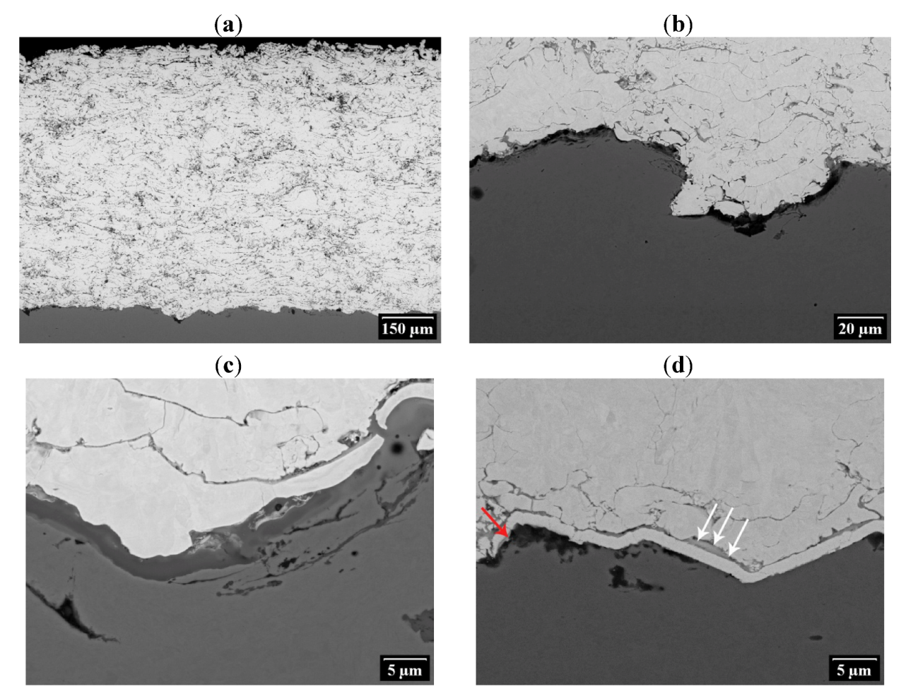
3.2. Observations of Coating and Interface Cross-Sections

3.3. Shear Adhesion Testing


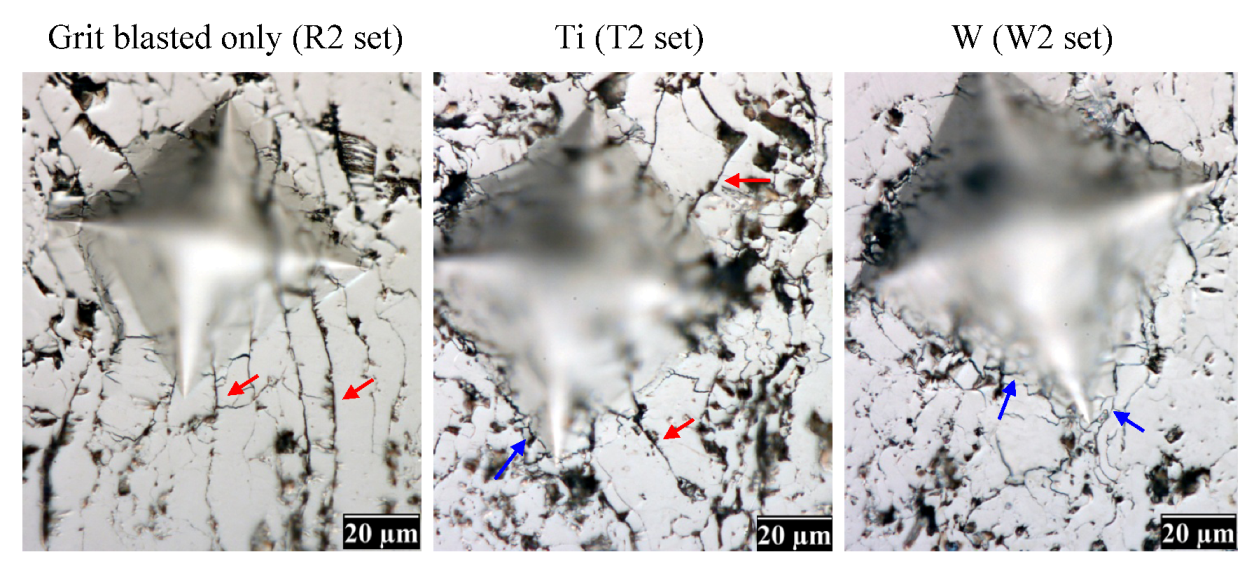
3.4. Observations of Fracture Surfaces and Interfaces


4. Conclusions
Acknowledgments
References
- Romanelli, F.; Barabaschi, P.; Borba, D.; Federici, G.; Horton, L.; Neu, R.; Stork, D.; Zohm, H. Fusion Electricity—A Roadmap to the Realisation of Fusion Energy; European Fusion Development Agreement: Garching, Germany, 2012. [Google Scholar]
- Bolt, H.; Barabash, V.; Krauss, W.; Linke, J.; Neu, R.; Suzuki, S.; Yoshida, N. Materials for the Plasma-Facing Components of Fusion Reactors. J. Nucl. Mater. 2004, 329, 66–73. [Google Scholar]
- Davis, J.W.; Barabash, V.R.; Makhankov, A.; Plochl, L.; Slattery, K.T. Assessment of Tungsten for Use in the ITER Plasma Facing Components. J. Nucl. Mater. 1998, 263, 308–312. [Google Scholar]
- Smid, I.; Akiba, M.; Vieider, G.; Plöchl, L. Development of Tungsten Armor and Bonding to Copper for Plasma- Interactive Components. J. Nucl. Mater. 1998, 263, 160–172. [Google Scholar]
- Pintsuk, G. Tungsten as a Plasma-Facing Material. In Comprehensive Nuclear Materials; Konings, R.J.M., Ed.; Elsevier: Amsterdam, The Netherland, 2012; pp. 551–581. [Google Scholar]
- Maier, H.; Neu, R.; Greuner, H.; Böswirth, B.; Balden, M.; Lindig, S.; Matthews, G.F.; Rasinski, M.; Wienhold, P.; Wiltner, A. Qualification of Tungsten Coatings on Plasma-Facing Components for JET. Phys. Scr. 2009, T138, 014031. [Google Scholar] [CrossRef]
- Matějíček, J.; Chráska, P.; Linke, J. Thermal Spray Coatings for Fusion Applications—Review. J. Thermal Spray Technol. 2007, 16, 64–83. [Google Scholar] [CrossRef]
- Matějíček, J.; Koza, Y.; Weinzettl, V. Plasma Sprayed Tungsten-based Coatings and their Performance under Fusion Relevant Conditions. Fusion Eng. Des. 2005, 75–79, 395–399. [Google Scholar] [CrossRef]
- Weiss, H. Adhesion of Advanced Overlay Coatings—Mechanisms and Quantitative Assessment. Surf. Coat. Technol. 1995, 71, 201–207. [Google Scholar] [CrossRef]
- Sobolev, V.V.; Guilemany, J.M.; Nutting, J.; Miquel, J.R. Development of Substrate-Coating Adhesion in Thermal Spraying. Int. Mater. Rev. 1997, 42, 117–136. [Google Scholar] [CrossRef]
- Mellali, M.; Fauchais, P.; Grimaud, A. Influence of Substrate Roughness and Temperature on the Adhesion/Cohesion of Alumina Coatings. Surf. Coat. Technol. 1996, 81, 275–286. [Google Scholar] [CrossRef]
- Staia, M.H.; Ramos, E.; Carrasquero, A.; Roman, A.; Lesage, J.; Chicot, D.; Mesmacque, G. Effect of Substrate Roughness Induced by Grit Blasting Upon Adhesion of WC-17% Co Thermal Sprayed Coatings. Thin Solid Films 2000, 377, 657–664. [Google Scholar]
- Vilémová, M.; Siegl, J.; Matějíček, J.; Mušálek, R. Effect of the Grit Blasting Exposure Time on the Adhesion of Al2O3 and 316L Coatings. In Thermal Spray 2011: Proceedings of the International Thermal Spray Conference (DVS-ASM), Hamburg, Germany, 2011; pp. 979–984.
- Wang, Y.Y.; Li, C.J.; Ohmori, A. Influence of Substrate Roughness on the Bonding Mechanisms of High Velocity Oxy-Fuel Sprayed Coatings. Thin Solid Films 2005, 485, 141–147. [Google Scholar] [CrossRef]
- Paredes, R.S.C.; Amico, S.C.; d'Oliveira, A.S.C.M. The Effect of Roughness and Pre-Heating of the Substrate on the Morphology of Aluminium Coatings Deposited by Thermal Spraying. Surf. Coat. Technol. 2006, 200, 3049–3055. [Google Scholar] [CrossRef]
- Dallaire, S. Influence of Temperature on the Bonding Mechanism of Plasma-Sprayed Coatings. Thin Solid Films 1982, 95, 237–244. [Google Scholar]
- Fukumoto, M.; Huang, Y. Flattening Mechanism in Thermal Sprayed Nickel Particle Impinging on Flat Substrate Surface. J. Thermal Spray Technol. 1999, 8, 427–432. [Google Scholar] [CrossRef]
- Jiang, X.Y.; Wan, Y.P.; Herman, H.; Sampath, S. Role of Condensates and Adsorbates on Substrate Surface on Fragmentation of Impinging Molten Droplets During Thermal Spray. Thin Solid Films 2001, 385, 132–141. [Google Scholar] [CrossRef]
- Qu, M.; Gouldstone, A. On the Role of Bubbles in Metallic Splat Nanopores and Adhesion. J. Thermal Spray Technol. 2008, 17, 486–494. [Google Scholar] [CrossRef]
- Tran, A.T.T.; Hyland, M.M.; Shinoda, K.; Sampath, S. Influence of Substrate Surface Conditions on the Deposition and Spreading of Molten Droplets. Thin Solid Films 2011, 519, 2445–2456. [Google Scholar] [CrossRef]
- McDonald, A.; Moreau, C.; Chandra, S. Thermal Contact Resistance between Plasma-Sprayed Particles and Flat Surfaces. Int. J. Heat Mass Transfer 2007, 50, 1737–1749. [Google Scholar] [CrossRef]
- Brossard, S.; Munroe, P.R.; Tran, A.T.T.; Hyland, M.M. Study of the Effects of Surface Chemistry on Splat Formation for Plasma Sprayed NiCr onto Stainless Steel Substrates. Surf. Coat. Technol. 2010, 204, 1599–1607. [Google Scholar] [CrossRef]
- Sabiruddin, K.; Bandyopadhyay, P.P.; Bolelli, G.; Lusvarghi, L. Variation of Splat Shape With Processing Conditions in Plasma Sprayed Alumina Coatings. J. Mater. Process. Technol. 2011, 211, 450–462. [Google Scholar] [CrossRef]
- Li, C.J.; Yang, G.J.; Li, C.X. Development of Particle Interface Bonding in Thermal Spray Coatings: A Review. J. Thermal Spray Technol. 2013, 22, 192–206. [Google Scholar] [CrossRef]
- Cho, G.S.; Choe, K.H. Characterization of Plasma-Sprayed Tungsten Coating on Graphite with Intermediate Layers. Surf. Coat. Technol. 2012, 209, 131–136. [Google Scholar] [CrossRef]
- Chong, F.L. Optimization of Plasma-Sprayed Tungsten Coating on Copper with the Heterogeneous Compliant Layer for Fusion Application. J. Thermal Spray Technol. 2013, 22, 57–60. [Google Scholar] [CrossRef]
- Matějíček, J.; Mušálek, R. Processing and Properties of Plasma Sprayed W+Cu Composites. In Thermal Spray 2008: Crossing Borders (DVS-ASM), Maastricht, The Netherland, 2008; pp. 1400–1405.
- Matějíček, J.; Boldyryeva, H. Processing and Temperature-Dependent Properties of Plasma Sprayed Tungsten-Stainless Steel Composites. Phys. Scr. 2009, T138, 014041. [Google Scholar] [CrossRef]
- Niu, Y.R.; Hu, D.Y.; Ji, H.; Huang, L.P.; Zheng, X.B. Effect of Bond Coatings on Properties of Vacuum Plasma Sprayed Tungsten Coatings on Copper Alloy Substrate. Fusion Eng. Des. 2011, 86, 307–311. [Google Scholar] [CrossRef]
- Weber, T.; Stüber, M.; Ulrich, S.; Vassen, R.; Basuki, V.; Lohmiller, J.; Sittel, W.; Aktaa, J. Functionally Graded Vacuum Plasma Sprayed and Magnetron Sputtered Tungsten/EUROFER97 Interlayers for Joints in Helium-Cooled Divertor Components. J. Nucl. Mater. 2013, in press.. [Google Scholar]
- Jung, Y.-I.; Park, J.-Y.; Choi, B.-K.; Lee, D.-W.; Cho, S. Interfacial Microstructures of HIP Joined W and Ferritic-Martensitic Steel with Ti Interlayers. Fusion Eng. Des. 2013, in press. [Google Scholar]
- Matějíček, J.; Neufuss, K.; Kolman, D.; Chumak, O.; Brožek, V. Development and Properties of Tungsten-Based Coatings Sprayed by WSP(R). In International Thermal Spray Conference, Basel, Switzerland, 2005; pp. 634–640.
- EN15340: Thermal spraying—Determination of Shear Load Resistance of Thermally Sprayed Coatings; European Committee for Standardization: Brussels, Belgium, 2007.
- Mušálek, R.; Pejchal, V.; Vilémová, M.; Matějíček, J. Multiple-Approach Evaluation of WSP Coatings Adhesion/Cohesion Strength. J. Thermal Spray Technol. 2013, 22, 221–232. [Google Scholar] [CrossRef]
- Matějíček, J.; Kavka, T.; Bertolissi, G.; Ctibor, P.; Vilémová, M.; Mušálek, R.; Nevrlá, B. The Role of Spraying Parameters and Inert Gas Shrouding in Hybrid Water-Argon Plasma Spraying of Tungsten and Copper for Nuclear Fusion Applications. J. Thermal Spray Technol. 2013, 22, 744–755. [Google Scholar]
- Kavka, T.; Matějíček, J.; Ctibor, P.; Hrabovský, M. Spraying of Metallic Powders by Hybrid Gas/Water Torch and the Effects of Inert Gas Shrouding. J. Thermal Spray Technol. 2012, 21, 695–705. [Google Scholar] [CrossRef]
- Web Elements. Available online: http://www.webelements.com (accessed on 15 April 2013).
- Zhou, G.J.; Zeng, D.C.; Liu, Z.W. Phase Equilibria in the Fe-Ti-Zr System at 1023 K. J. Alloys Compd. 2010, 490, 463–467. [Google Scholar] [CrossRef]
- Calculated Ti-W phase diagram. Available online: http://resource.npl.co.uk/mtdata/phdiagrams/tiw.htm (accessed on 15 April 2013).
- Niu, Y.R.; Zheng, X.B.; Ji, H.; Qi, L.J.; Ding, C.X.; Chen, J.L.; Luo, G.N. Microstructure and Thermal Property of Tungsten Coatings Prepared by Vacuum Plasma Spraying Technology. Fusion Eng. Des. 2010, 85, 1521–1526. [Google Scholar] [CrossRef]
- Tran, A.T.T.; Hyland, M.M. Bubble Formation in NiCr Splat on Aluminum Substrate during Plasma Spray: Surface Chemistry Effect. IOP Conf. Ser. Mater. Sci. Eng. 2009, 012007. [Google Scholar] [CrossRef]
© 2013 by the authors; licensee MDPI, Basel, Switzerland. This article is an open access article distributed under the terms and conditions of the Creative Commons Attribution license (http://creativecommons.org/licenses/by/3.0/).
Share and Cite
Matějíček, J.; Vilémová, M.; Mušálek, R.; Sachr, P.; Horník, J. The Influence of Interface Characteristics on the Adhesion/Cohesion of Plasma Sprayed Tungsten Coatings. Coatings 2013, 3, 108-125. https://doi.org/10.3390/coatings3020108
Matějíček J, Vilémová M, Mušálek R, Sachr P, Horník J. The Influence of Interface Characteristics on the Adhesion/Cohesion of Plasma Sprayed Tungsten Coatings. Coatings. 2013; 3(2):108-125. https://doi.org/10.3390/coatings3020108
Chicago/Turabian StyleMatějíček, Jiří, Monika Vilémová, Radek Mušálek, Pavel Sachr, and Jakub Horník. 2013. "The Influence of Interface Characteristics on the Adhesion/Cohesion of Plasma Sprayed Tungsten Coatings" Coatings 3, no. 2: 108-125. https://doi.org/10.3390/coatings3020108