Article

Broadband Solar Energy Absorption in Plasmonic Thin-Film Amorphous Silicon Solar Cell

1
Department of Electrical Engineering, Sarhad University of Science & Information Technology, Peshawar 25000, Pakistan
2
US–Pakistan Center for Advanced Studies in Energy, University of Engineering & Technology, Peshawar 25000, Pakistan
3
Department of Computer System Engineering, University of Engineering & Technology, Peshawar 25000, Pakistan
4
Department of Electrical Engineering, University of Engineering & Technology, Mardan 23200, Pakistan
*
Author to whom correspondence should be addressed.
Coatings 2019, 9(10), 638; https://doi.org/10.3390/coatings9100638
Submission received: 29 August 2019 / Revised: 19 September 2019 / Accepted: 24 September 2019 / Published: 3 October 2019

Abstract

:
Improving the light absorption in thin-film solar cell is essential for enhancing efficiency and reducing cost. Here, we propose an ultra-broadband amorphous silicon solar cell based on a periodic array of titanium ring-shaped metasurfaces, which achieves more than 90% absorptance in the visible range of the solar spectrum. The surface plasmon resonance supported by the nanoparticles together with the resonance induced by the metal–insulator–metal Fabry–Perot cavity leads to this broadband absorption. The impact of various materials of functional layers and the geometric structure of the nanoparticle on absorption performance is discussed in detail, and super broadband resonance is achieved after optimization. Moreover, the optimized solar cell is tested for different solar incidence angles and it is found that the structure exhibits high absorption efficiency even at large angles. Thus, the proposed solar cell design may be beneficial for most of the photovoltaic applications.

1. Introduction

Solar photovoltaics are mainly dominated by mono- and multi-crystalline silicon solar cells due to their reliability and stability in terms of power efficiency. However, the cost is comparatively high as silicon-based solar cells require a thick silicon wafer to trap the maximum amount of incident light. To overcome this problem, thin-film-based solar cells are being extensively used now a days [1,2]. The only problem with thin-film-based solar cells is the output efficiency, which is relatively less than that of the conventional silicon-based solar cells [3,4]. Henceforth, the main challenge with thin-film technology is to improve the output efficiency in order to take full advantage of low engineering cost. The thin-film technology suffers enormously from optical losses due to a thin absorber layer, which makes it difficult to trap all the incident photons. The usual solution to this problem is aggressive texturing of the interfaces, which basically improves the trapping ability of photons [3,4,5]. However, such excessively textured interfaces will lead to some defects, which may give rise to significant recombination losses and ultimately reduce the overall efficiency [6]. Therefore, a highly efficient light trapping technique is needed that can trap the maximum number of photons inside a thin absorbing layer. These light trapping techniques include: anti-reflection coating [7], photonic crystals [8], and metallic nanoparticles [9,10,11] that reduce the reflection losses at the top surface and decrease the transmission of photons at the rear surface.
Rufangura et al. suggested an optical structure for solar cells, where they used gold and GaAs patches on the top surface and obtained dual narrow absorption modes with 99% absorption level [12]. Wang et al. designed an optical structure for a-Si:H thin-film solar cells, where an array of silver nanoparticles at the bottom surface is used and approximately 60% light absorption efficiency is achieved with a spectral width of 200 nm [13]. Lou et al. proposed a new light trapping structure by using gold nanoparticles at the back surface and attained 60% optical absorption efficiency with a bandwidth of 250 nm [14]. Recently, Chen et al. proposed a new design of amorphous silicon (a-Si) thin-film cell where they used a bilayer Al–Ag grating in combination with a SiO2 layer on the top surface, and an Ag mirror at the bottom surface. They managed to achieve 78% optical absorption efficiency in the wavelength range of 370–580 nm [15].
In this work, we studied the optical properties of a novel a-Si solar cell, which is based on titanium (Ti) ring-shaped nanoparticles that exhibit broadband absorption resonance in the visible region. This broadband response appears due to the interaction of localized surface plasmons of the nanoring and the metal–insulator–metal cavity modes. By optimizing geometric properties, the average absorption in the active layer can reach 96.03%. Furthermore, the solar cell exhibits better absorption efficiency even for higher incidence angles, which suggests that the proposed design can effectively contribute in solving the issue of high power conversion efficiency.

2. Structure Design and Methods

Figure 1a shows the schematic of an ultra-thin a-Si solar cell, which consists of five operational layers; (i) An array of circular metal nanorings made of Ti are deposited at the top surface, which is responsible for minimizing the reflection of incident light and guiding the incoming light into the absorber medium, (ii) a bi-layer antireflection coating (ARC) made of SiO2 and Si3N4 materials is placed below the Ti nanorings, which will further reduce the reflection of light from the top surface with the help of the destructive interference phenomenon, (iii) an active layer, made of a-Si material, which is responsible for trapping photons and converting them into electron–hole pairs, (iv) a back-surface reflector, made of Ti metal film, which will prevent the transmission of low-energetic photons because such photons usually escape from the cell, and (v) an additional glass layer made of quartz is also used on the top of nanorings for protection. This layer is extremely thermally shock resistant, highly transparent for light from the ultraviolet to infrared region, best for chemical resistance, and an excellent electrical insulator [16]. The period of unit cell along x and y shown in Figure 1b is px = p = py = 400 nm; the widths of the circular nanorings are: wr1 = 40 nm, wr2 = 40 nm; the gap between two rings, wgap = 40 nm; size of ring1, Ca = 180 nm; and ring2, Cb = 100 nm; the thickness of both nanorings is, tt = 20 nm; thickness of ARC layer 1, tarc1 = 20 nm; thickness of ARC layer 2, tarc2 = 30 nm; thickness of absorbing layer, tabs = 110 nm; thickness of back-surface reflector, tbsf = 40 nm; and thickness of glass, tg = 20 nm, respectively. The complex dielectric function of Ti and a-Si is obtained using the Johnson and Christy model and the data are taken from [17]. The dielectric constants of SiO2 and Si3N4 are chosen as 3.9 [18] and 7.4 [19], respectively. The periodic conditions are applied for the duplication of unit cells in the x and y directions. The simulation environment is selected as air and all simulations are performed in the COMSOL Multiphysics software v5.3 [20].

3. Results and Discussion

To understand the underlying physics and to achieve high broadband optical absorption efficiency, we divided the proposed model into various sections as shown in Figure 2. Here, Figure 2a is considered to be a reference section (S1), which contains only the absorber and back reflector layers. Figure 2b shows a second section (S2), which contains a single layer ARC made of SiO2 along with the absorber and Ti metal layers. Figure 2c represents a third section (S3), where the ARC is replaced by a single Ti resonator. Figure 2d denotes section S4, where bimetallic resonators are deposited on top of the absorber layer. In section S5, a single ARC layer is used along with Ti nanorings as shown in Figure 2e, and Figure 2f represents a complete structure of the proposed model (S6), where a glass layer is also used at the top surface of the cell for protection.
The absorption characteristics of all the sections are measured and compared with each other as shown in Figure 3a. The absorption spectra of S1 is approximately 50% for few wavelengths due to high reflection losses from the top surface. However, adding the ARC layer (S2) improves the absorbance up to 62% because the ARC has minimized some of the reflection losses as indicated by the blue curve. The absorption efficiency of S3 is further improved, i.e., 66.62%, compared to the reference structure because surface plasmons are greatly excited by nanoparticles, which scattered the incoming photons into the a-Si absorber layer [21]. Now, by using a double-layered resonator (S4), the light absorption efficiency is remarkably enhanced up to 75.3%. Again, the surface plasmons supported by the two nanoparticles strongly couple and increase the scattering of photons in the absorber layer. Furthermore, by inserting an ARC between the resonators and the absorber layer (S5), the efficiency is increased more than 80% as indicated by the sky-blue curve. To achieve complete optical absorption, another ARC layer of Si3N4 material is added along with glass layer at the top surface (S6), which dramatically enhanced the efficiency above 90% as indicated by the pink curve. Here, the absorption spectra are improved by 40% from 300 to 700 nm compared to the reference cell with an average absorbance rate of more than 96.03%. The highest resonance peak reached up to 99.96% at 647 nm. For further details, we also calculated the absorption versus reflection and transmission spectra of S6 structure for the visible region as shown in Figure 3b. Here, the transmission losses are nearly zero, while the reflection losses are less than 1% for the entire wavelength range.

3.1. Influence of Resonator on Absorption Spectra

As discussed above, metallic nanoparticles exhibit surface plasmon resonances (SPRs) when hit by the incident electromagnetic wave. Such SPRs boost the strength of photons, which essentially absorbs in the active layer [22]. It is to be noted that the optical absorption properties are strongly dependent on geometric parameters of the nanoparticles [23]. So, in this way, by changing the parameters of the nanorings, the absorption efficiency of the whole structure can be effectively modified [24]. Figure 4a represents the absorption characteristics of the solar cell by varying the thickness of the resonator from 10 to 70 nm. It appears that as the thickness increases, the level of absorption improves for both short and long wavelengths. This means that a lower value of the thickness is not adequate for efficient coupling with the incoming photons; therefore, it does not generate a high broadband absorption mode in the visible region.
The width parameter of the nanorings also contributes well in modifying the absorption properties of thin-film solar cells. Here, first we varied the width of the outer nanoring, wr1, by a step of 10 nm from 10 to 80 nm and keeping all other parameters fixed, as shown in Figure 4b. It is observed that the absorption spectrum is improved at short wavelength and drops at long wavelength when the width value decreases, i.e., below 40 nm and vice versa as indicated in the inset. This is because the structures with lesser width are more transparent to high-frequency photons compared to low-frequency photons. Similarly, the width of the inner nanoring, wr2, is also varied from 10 to 80 nm as shown in Figure 4c. It appears that in this case, the absorption characteristics are almost independent of wr2.
The influence of period, p, over the absorption efficiency is also examined as shown in Figure 4d. It is observed that the absorption at long wavelength becomes slightly weaker as the period increases. This is because a large period means a large gap between the two unit cells, resulting in a weaker interaction of the surface plasmons. So, in order to attain a high broadband optical efficiency, the period of the unit cell should be small. The light absorption behavior and flexibility of the suggested structure on material selection for the top nanorings is also studied as shown in Figure 4e. Here for comparison, we tested gold (Au), silver (Ag), copper (Cu), nickel (Ni), and aluminum (Al), respectively. It was found that Ti-based nanoparticles possess high broadband absorption resonances among others in the whole optical spectrum due to the metal’s intrinsic dispersion property.

3.2. Influence of Absorbing Layer

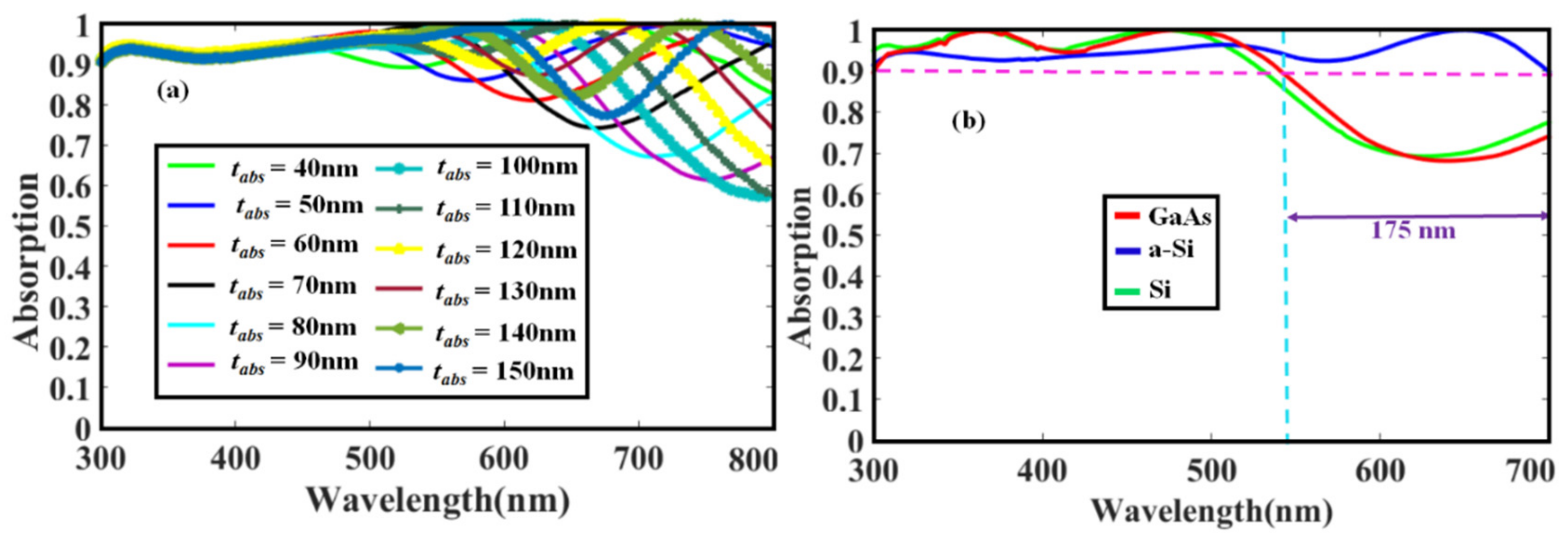
The active region of the solar cell plays a critical role because the absorption of incoming photons and carrier production take place in this regime [25,26]. To optimize this region, we first varied the thickness from 40 to 150 nm as shown in Figure 5a. It is observed as the thickness increases from 40 to 110 nm, the trapping density of incoming photons also increases and covers the entire visible region of the solar spectrum. This is due to the fact that large thickness of the active layer will trap the maximum amount of photons, which will be converted into electron–hole pairs. Moreover, if we keep the thickness of the active layer small, it is possible that low-energetic light passes through the active layer without being absorbed. However, if we keep increasing the thickness further, i.e., from 110 to 150 nm, the absorption efficiency at long wavelength starts contributing to optical losses because absorption efficiency starts fading gradually. This is because a thicker absorber layer will minimize the refractive index, which will highly increase the transmission and reflection losses in solar cells and result in the suppression of optical absorption efficiency [27]. So, in this case, the optimized thickness is 110 nm, because it covers the whole visible region i.e., from 300 to 700 nm with more than 90% absorption level.
Next we investigated different materials for the absorber layer as shown in Figure 5b. Here we replaced a-Si by crystalline Si and GaAs and compared their results. It can be observed that a-Si possesses higher broadband optical absorption than other materials as indicated by blue curve. Therefore, a-Si is advantageous in thin-film solar cell because it is highly sensitive to the visible spectrum i.e., it has more ability to collect photons in a lower light situation, is lighter in weight, more durable, highly flexible, has low sensitivity to high temperature, and is cheaper in cost [28].

3.3. Effect of the Back Reflector

As discussed, the optimization of the front surface and active layer is necessary because some incident light reflects due to the high refractive index of the absorber material. Similarly, optimization of the back surface is also important because a part of the low-energetic light passes through the cell without being absorbed. For undertaking this issue, we investigated different materials for the back surface such as Ag, Al, Au, Cu, Ni, and Ti as shown in Figure 6. It was observed that all the materials except Ti exhibit comparatively poor performance in the long-wavelength region. Therefore, in our proposed structure, the preferable material for this layer is Ti.

3.4. Electric Field Distribution Profile

To explicitly show the electric field distributions inside the active layer of the optimized structure, we plotted the field profile as revealed in Figure 7. It is found that most of the high energy photons are enhanced by an enhancement factor of five in the active layer, which improves the light absorption in greater amounts.

3.5. Effect of Different Incident Angles

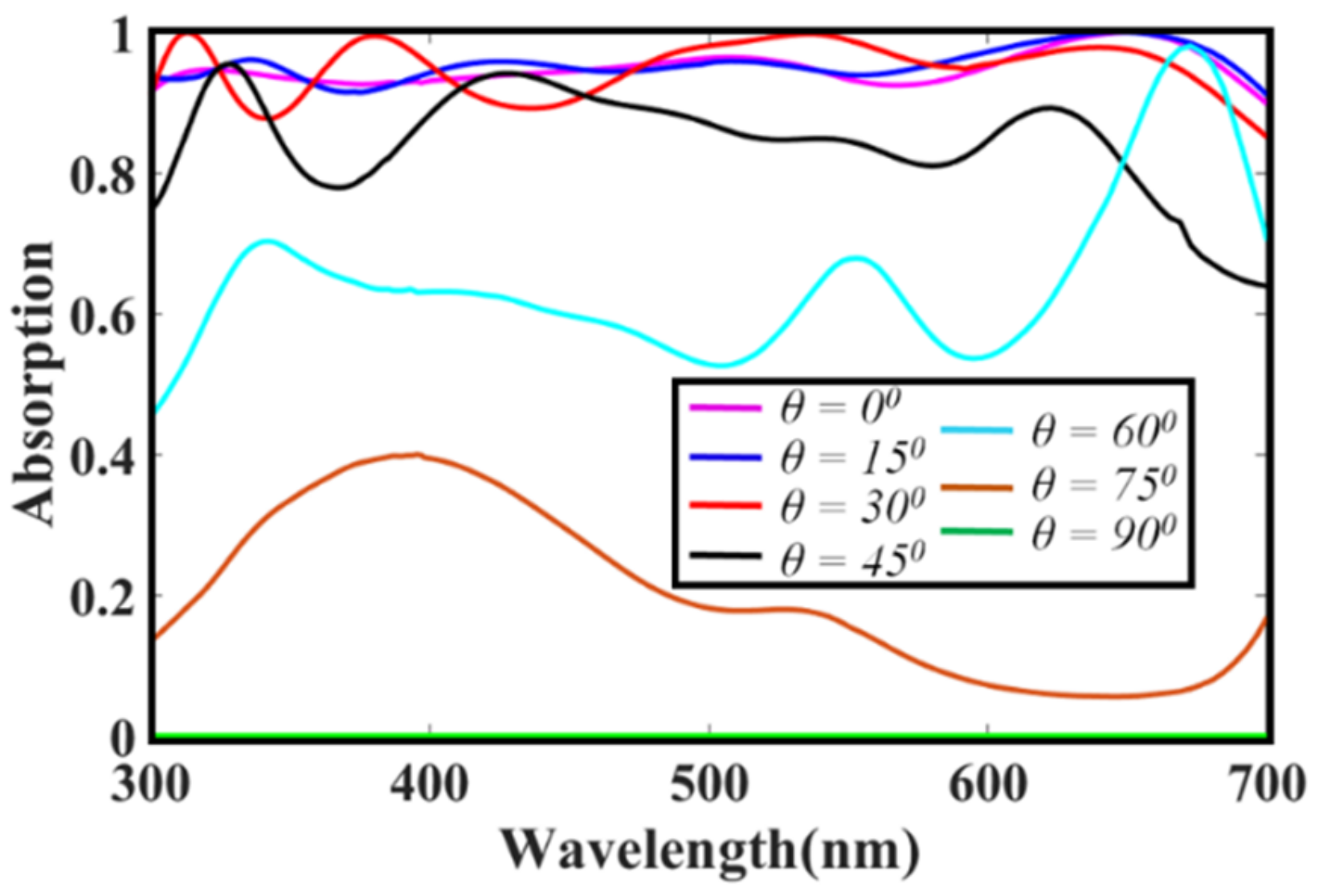
It is well known that the solar incidence angle plays a vital role on the performance of solar cells. Throughout the day, the sun angle falling on the solar cell changes from morning to afternoon and significantly affects the trapping of photons inside the solar cell, hence disturbing the efficiency. Therefore, the impact of the solar incidence angle, θ, which is the angle between the incoming photons and the normal on the solar cell surface, on the absorption efficiency is shown in Figure 8. It can be seen that for θ = 0°–45°, the absorption spectra of the proposed structure is weakly affected, this is due to the presence of nanoparticles and the ARC layer because they guide the solar cell to essentially capture more incident photons into the active layer [29]. However, above 45°, the absorption spectra suffer from high optical losses because the light does not efficiently couple to the structure, thus, the performance reduces.

4. Conclusions

We have demonstrated a simple design of a-Si solar cell based on ring-shaped Ti nanoparticles that enables ultra-broadband absorption over the energy-rich portion of the solar spectrum. The materials of functional layers and the geometric parameters of the nanorings are optimized to get broadband absorption from 300 to 700 nm with an average absorption rate of more than 96% in the active region. Furthermore, the absorption efficiency of the solar cell is evaluated for different incident angles and it is found that the cell shows good performance even in the worst conditions. Thus, we believe that the proposed cell, relatively simple but effective, may be suitable to design highly efficient and low-cost photovoltaics of the next generation.

Author Contributions

Conceptualization, A.D.K. and Q.R.; methodology, A.D.K.; software, F.E.S.; validation, M.N., A.D.K. and S.A.; formal analysis, S.A.; investigation, A.D.K. and Q.R; resources, H.A.K.; data curation, H.A.K.; writing—original draft preparation, A.D.K.; writing—review and editing, M.N.; visualization, S.A.; supervision, A.D.K.; project administration, A.D.K.; funding acquisition, H.A.K.

Funding

This research did not receive any specific grant from funding agencies in the public, commercial, or not-for-profit sectors.

Conflicts of Interest

The authors declare no conflict of interest.

References

  1. Green, M.A.; Emery, K.; Hishikawa, Y.; Warta, W. Solar cell efficiency tables (version 37). Prog. Photovolt. Res. Appl. 2011, 19, 84–92. [Google Scholar] [CrossRef]
  2. Meier, J.; Spitznagel, J.; Kroll, U.; Bucher, C.; Fay, S.; Moriarty, T.; Shah, A. Potential of amorphous and microcrystalline silicon solar cells. Thin Solid Film. 2004, 451, 518–524. [Google Scholar] [CrossRef]
  3. Wang, Y.; Sun, T.; Paudel, T.; Zhang, Y.; Ren, Z.; Kempa, K. Metamaterial-plasmonic absorber structure for high efficiency amorphous silicon solar cells. Nano Lett. 2011, 12, 440–445. [Google Scholar] [CrossRef] [PubMed]
  4. Khan, A.D.; Iqbal, J.; ur Rehman, S. Polarization-sensitive perfect plasmonic absorber for thin-film solar cell application. Appl. Phys. A 2018, 124, 610. [Google Scholar] [CrossRef]
  5. Patel, S.K.; Charola, S.; Parmar, J.; Ladumor, M. Broadband metasurface solar absorber in the visible and near-infrared region. Mater. Res. Express 2019, 6, 086213. [Google Scholar] [CrossRef]
  6. Ferry, V.E.; Verschuuren, M.A.; Li, H.B.; Verhagen, E.; Walters, R.J.; Schropp, R.E.; Atwater, H.A.; Polman, A. Light trapping in ultrathin plasmonic solar cells. Opt. Express 2010, 18, A237–A245. [Google Scholar] [CrossRef] [PubMed] [Green Version]
  7. Lee, Y.J.; Ruby, D.S.; Peters, D.W.; McKenzie, B.B.; Hsu, J.W. ZnO nanostructures as efficient antireflection layers in solar cells. Nano Lett. 2008, 8, 1501–1505. [Google Scholar] [CrossRef]
  8. Bermel, P.; Luo, C.; Zeng, L.; Kimerling, L.C.; Joannopoulos, J.D. Improving thin-film crystalline silicon solar cell efficiencies with photonic crystals. Opt. Express 2007, 15, 16986–17000. [Google Scholar] [CrossRef]
  9. Atwater, H.A.; Polman, A. Plasmonics for improved photovoltaic devices. Nat. Mater. 2010, 9, 205. [Google Scholar] [CrossRef]
  10. Khan, A.D.; Khan, A.D.; Khan, S.D.; Noman, M. Light absorption enhancement in tri-layered composite metasurface absorber for solar cell applications. Opt. Mater. 2018, 84, 195–198. [Google Scholar] [CrossRef]
  11. Katrodiya, D.; Jani, C.; Sorathiya, V.; Patel, S.K. Metasurface based broadband solar absorber. Opt. Mater. 2019, 89, 34–41. [Google Scholar] [CrossRef]
  12. Rufangura, P.; Sabah, C. Design and characterization of a dual-band perfect metamaterial absorber for solar cell applications. J. Alloy. Compd. 2016, 671, 43–50. [Google Scholar] [CrossRef]
  13. Wang, P.; Theuring, M.; Vehse, M.; Steenhoff, V.; Agert, C.; Brolo, A. Light trapping in a-Si:H thin film solar cells using silver nanostructures. AIP Adv. 2017, 7, 015019. [Google Scholar] [CrossRef]
  14. Luo, Q.; Zhang, C.; Deng, X.; Zhu, H.; Li, Z.; Wang, Z.; Chen, X.; Huang, S. Plasmonic effects of metallic nanoparticles on enhancing performance of perovskite solar cells. ACS Appl. Mater. Interfaces 2017, 9, 34821–34832. [Google Scholar] [CrossRef] [PubMed]
  15. Chen, Y.; Wen, L.; Hu, X.; Xu, R.; Chen, Q. Discrete optical field manipulation by Ag–Al bilayer gratings for broadband absorption enhancement in thin-film solar cells. Plasmonics 2018, 13, 1603–1613. [Google Scholar] [CrossRef]
  16. Katagiri, H.; Jimbo, K.; Maw, W.S.; Oishi, K.; Yamazaki, M.; Araki, H.; Takeuchi, A. Development of CZTS-based thin film solar cells. Thin Solid Film. 2009, 517, 2455–2460. [Google Scholar] [CrossRef]
  17. Ni, X.; Liu, Z.; Kildishev, A.V. PhotonicsDB: Optical Constants; Network for Computational Nanotechnology: West Lafayette, IN, USA, 2007. [Google Scholar]
  18. Gospodinova-Daltcheva, M.; Arnaudov, R.; Philippov, P. Energy propagation properties of Al-lossy lines in high-speed circuits on silicon substrate. In Proceedings of the 1999 Symposium on High Performance Electron Devices for Microwave and Optoelectronic Applications, London, UK, 23 November 1999; pp. 295–300. [Google Scholar]
  19. Kitamura, K.; Takebayashi, H.; Hattori, T. Rolling Bearing Having Rolling Elements Whose Major Component Is Zirconia. U.S. Patent 6,174,089, 16 January 2001. [Google Scholar]
  20. Zimmerman, W.B. Multiphysics Modeling with Finite Element Methods; World Scientific Publishing Company: Singapore, 2006. [Google Scholar]
  21. Homola, J.; Yee, S.S.; Gauglitz, G. Surface plasmon resonance sensors. Sens. Actuators B Chem. 1999, 54, 3–15. [Google Scholar] [CrossRef]
  22. Khan, A.D.; Amin, M. Tunable salisbury screen absorber using square lattice of plasmonic nanodisk. Plasmonics 2017, 12, 257–262. [Google Scholar] [CrossRef]
  23. Schuller, J.A.; Barnard, E.S.; Cai, W.; Jun, Y.C.; White, J.S.; Brongersma, M.L. Plasmonics for extreme light concentration and manipulation. Nat. Mater. 2010, 9, 193. [Google Scholar] [CrossRef]
  24. Kelly, K.L.; Coronado, E.; Zhao, L.L.; Schatz, G.C. The Optical Properties of Metal Nanoparticles: The Influence of Size, Shape, and Dielectric Environment; ACS Publications: Washington, DC, USA, 2003. [Google Scholar]
  25. Khan, A.D.; Khan, A.D. Optimization of highly efficient GaAs–Silicon hybrid solar cell. Appl. Phys. A 2018, 124, 851. [Google Scholar] [CrossRef]
  26. Woo, K.; Kim, Y.; Moon, J. A non-toxic, solution-processed, earth abundant absorbing layer for thin-film solar cells. Energy Environ. Sci. 2012, 5, 5340–5345. [Google Scholar] [CrossRef]
  27. Moulé, A.J.; Bonekamp, J.B.; Meerholz, K. The effect of active layer thickness and composition on the performance of bulk-heterojunction solar cells. J. Appl. Phys. 2006, 100, 094503. [Google Scholar] [CrossRef]
  28. Carlson, D.E.; Wronski, C.R. Amorphous silicon solar cell. Appl. Phys. Lett. 1976, 28, 671–673. [Google Scholar] [CrossRef]
  29. Yang, M.; Fu, Z.; Lin, F.; Zhu, X. Incident angle dependence of absorption enhancement in plasmonic solar cells. Opt. Express 2011, 19, A763–A771. [Google Scholar] [CrossRef] [PubMed]
Figure 1. (a) Schematic view of the proposed structure, (b) view of the single unit cell, and (c) dual metallic ring resonator.
Coatings 09 00638 g001
Figure 2. Schematic structure of (a) reference solar cell (S1), (b) solar cell with single antireflection coating (ARC) layer (S2), (c) solar cell with single nanoring (S3), (d) solar cell with double nanorings (S4), (e) solar cell with double nanorings and ARC layer (S5), and (f) a complete solar cell (S6).
Coatings 09 00638 g002
Figure 3. (a) Comparison of absorption spectra of S1, S2, S3, S4, S5, and S6 structures and (b) reflection, transmission, and absorption spectra of S6 solar cell.
Coatings 09 00638 g003
Figure 4. Impact of optical absorption efficiency on (a) thickness of nanorings, and (b) width of the outer nanoring, wr1, (c) width of the inner ring, wr2, (d) period of unit cell, and (e) different materials for the top nanorings.
Coatings 09 00638 g004
Figure 5. Influence of (a) thickness of the absorbing layer and (b) different materials on absorption efficiency.
Coatings 09 00638 g005
Figure 6. Influence of optical absorption efficiency on different materials for the back-surface reflector.
Coatings 09 00638 g006
Figure 7. Map of electric field distribution inside the absorber layer versus the wavelength.
Coatings 09 00638 g007
Figure 8. Absorption spectra for different incidence angles.
Coatings 09 00638 g008