1. Introduction
Graphenaceous (i.e., graphene/graphene oxide-containing) materials (GM) are widely sought after to be employed as reinforcements in metal, polymer, and ceramic matrix composites to enhance their mechanical, thermal, electrical, tribological, and other functional properties [
1,
2,
3,
4,
5]. Although graphene research has witnessed remarkable breakthroughs and its supremely attractive combination of properties, mentioned above, are well recognized, realizing graphene’s commercially relevant application relies on the development of scalable processing techniques for its synthesis as well as its subsequent utilization.
Thermal spraying is a mature technology that is already industrially adopted for the deposition of large-area protective coatings. Although the conventional practice is to predominantly use powders as the starting materials, the idea of utilizing liquid feedstock (e.g., suspensions and solution precursors), either by itself or in combination with a powder, has recently attracted attention and has been successfully demonstrated by the authors [
6,
7,
8]. Previously published but practically unrealistic, curiosity-driven conventional plasma spraying processes have used ball milling to pre-mix graphene nano-platelets with the matrix powder [
5], which leaves the feedstock prone to segregation in flight due to the vast density differences. In contrast, the proposed suspension plasma spraying (SPS) approach is considered far more promising to spray GM-containing coatings by virtue of the flexibility it offers, apart from the more intimate mixing of constituents that is possible in the starting suspension.
Utilizing suspensions for thermal spraying allows the spraying of high-temperature/heat-sensitive materials since the suspended material is “shielded” by a liquid droplet during the early stages of flight. Moreover, SPS has been shown to be a versatile thermal spray variant, capable of spraying a wide range of ceramic materials for different applications, including thermal barriers, tribology, corrosion, solid oxide fuel cells, etc. [
9]. The dispersion of GM in a suitable liquid medium like an ethanol/water mixture [
10] has already been reported. However, only one prior thermal spray study has reported the use of a GM-containing suspension and, that too, was by high-velocity oxy-fuel (HVOF) spraying [
11], a process that is not as versatile as plasma spraying and has limitations in depositing materials such as zirconia.
It is important to point out that, if one would only consider graphene incorporation, lower-temperature processes like HVOF and high-velocity air fuel (HVAF) are prima facie more conducive than SPS, from a graphene retention point of view. However, the flexibility of SPS in enabling the incorporation of graphene into a ceramic matrix, such as a zirconia coating, is clearly more promising. Additionally, as reported in the literature [
9,
12,
13], a wide process window for depositing coatings via the SPS route is a distinct advantage; it expands the range of materials that can be sprayed, incorporating the highly temperature-sensitive materials like GM that are attempted in this work.
The present work is motivated by an interest in harnessing the SPS route to conveniently deposit large-area graphenaceous composite coatings that can spur a new generation of graphene-based applications. As proof of the concept’s effort, this study considers one of the most common materials deposited by SPS, i.e., yttria-stabilized-zirconia (YSZ), as the matrix material to be reinforced with graphene oxide (GO) for potential improvements in its functional properties [
6]. A microstructural analysis by scanning electron microscopy (SEM) and a phase analysis by Raman spectroscopy were carried out on the graphenaceous (GO-8YSZ) composite coatings to confirm the retention of few-layered graphene (FLG) in the deposited coatings. The results suggest that SPS could provide an exciting approach for recognizing the potential of the large-scale deposition of coatings incorporating graphenaceous materials for various applications.
2. Experimental Work
An 8YSZ-GO mixed suspension was first prepared by simply mixing a commercially available 4 wt.% solid-loaded, water-based GO suspension (2D fab AB, Sundsvall, Sweden) [
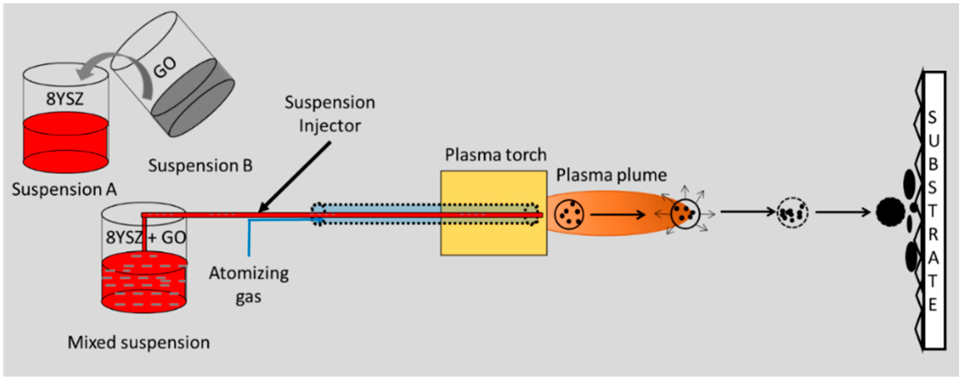
14] with an 8YSZ suspension (Innovnano, Coimbra, Portugal). The 8YSZ suspension contained particles with a median size of 400 nm and a 25 wt.% solid load in a 50:50 (wt.%) water-ethanol solvent. It must be pointed out that, since the overarching objective was to only demonstrate the incorporation of graphenaceous material in a 8YSZ matrix as proof of the concept, an 8YSZ water-ethanol suspension readily available in the authors’ laboratory was used for this study. It was further deemed that, if graphenaceous material could be retained while spraying such a suspension, it would subsequently be even easier to do so with an ethanol-based YSZ suspension that would demand relatively lower power levels for the deposition. The above mixed 8YSZ-GO suspension was then sprayed (
Figure 1) on steel coupons (φ25 mm × 6 mm) using an Axial III plasma torch (Northwest Mettech Corp., Surrey, BC, Canada). Prior to the coating deposition, the substrates were grit-blasted using Alumina grit, resulting in surface roughness of
Ra 3–4 μm. The process parameters used in this work, based on extensive prior experimentation conducted by our group in depositing 8YSZ coatings for TBC (Thermal Barrier Coating) applications using SPS [
6,
15], are tabulated in
Table 1. It is important to point out that the Mettech Axial III plasma torch consists of three electrodes. Therefore, the actual power reported in
Table 1, which is recorded from the Axial III controller, is the cumulative power from all three electrodes.
The morphology of 8YSZ and GO present in the mixed suspension, as well as on the top surface of the coatings, and the microstructures of the fractured and polished cross-sections were analyzed using scanning electron microscopy (SEM) (TM3000 (HITACHI, Tokyo, Japan) and Leo1550 Gemini (Zeiss, Oberkochen, Germany). The Raman spectra were recorded in the spectral region of 200–3500 cm−1 in the air using an Nd-YAG laser (wavelength = 532 nm) operated at 40 mW of power in the back-scattering geometry. A CRM spectrometer equipped with a confocal microscope (Model Alpha 300, WiTec, Ulm, Germany) was used to identify the phases in the coatings.
3. Results and Discussion
As shown in
Figure 2, the micrographs of a sample of the mixed suspension reveal GO (marked by the white solid arrows) distributed throughout, along with the predominant 8YSZ. Post-spraying, as observed from
Figure 2, it is not possible to clearly establish, merely based on the surface morphology of the coatings, that all of the three spray conditions led to the retention of GM. The exact identification of the phases and any confirmation of whether the noted GM is GO or a few-layered graphene (FLG) is, however, possible from Raman spectroscopy, as shown later in the work. Coating A, sprayed at the lowest plasma power conditions, exhibited the highest GM presence on the coating surface. The amount of GM visually seen on the surface was found to decrease with an increasing plasma power, with Coating C showing the least amount of GM. It is plausible that the very high thermal energy in the plasma plume, as in the case of Coating C, may have converted the majority of the GM into CO
2 during the spraying.
The direct consequence of varying the plasma power during the spraying is also evident in the cross-sectional micrographs of the coatings (
Figure 2). Coating C shows a typically dense, vertically-cracked structure, as previously reported at a high plasma power [
6]. On the other hand, Coating A reveals a negligible coating thickness due to the very low power that was perhaps insufficient to adequately melt the 8YSZ particles, resulting in them impacting the substrate in a largely unmolten condition and not depositing on the substrate. However, the polished cross-section of the coating deposited at a power level intermediate between the two extremes (Coating B) shows a reasonable coating build-up and, as previously seen from the coatings’ surface morphology, it also shows the presence of GM throughout the coating’s surface. It should be pointed out that two distinct zones are noticeable in Coating B, which are marked as Zone I and Zone II (
Figure 2). Of these, the dense Zone I region results from well-formed splats of molten particles arriving at the substrate, while the relatively porous Zone II is a consequence of partially molten or un-molten 8YSZ particles impacting the substrate.
Based on the surface morphologies and cross-sections of the coatings observed in
Figure 2, it can be concluded that the use of an appropriate power level, that ensures both a satisfactory deposition of the matrix phase (in the present case, 8YSZ) as well as the retention of GM, is best suited for spraying such graphenaceous composite coatings. To better visualize the through-thickness of the GM incorporation, the fractured cross-section of Coating B was further analyzed (
Figure 2). It was observed that the GM existence among the ceramic grains and through the thickness of the composite coating was visible at numerous locations, thereby supporting the above observation. Although the relatively more intimate mixing that is possible in a mixed suspension, compared to a dry powder form, is expected to suppress the material segregation in the coating, there is no evidence to confirm this based on this preliminary study which is primarily intended to demonstrate the convenient incorporation of GM via the SPS route. However, more careful further experimentation and process validation to substantiate the above hypothesis and assess the performance benefits are clearly motivated by these results.
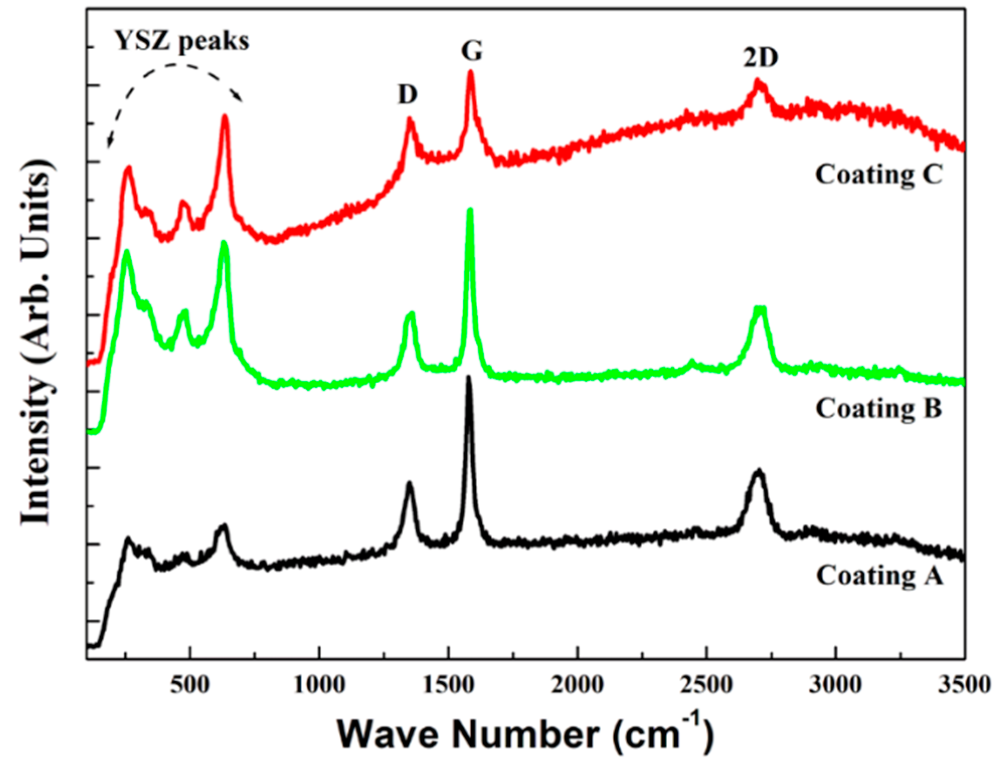
Figure 3 shows the appearance of the characteristic Raman bands, namely the disorder-induced D band, the graphitic G band, and the 2D band, confirming that all of the coatings contained GM. The higher intensity of the G band in comparison to that of the D band in Coating A and Coating B indicates the presence of good-quality regular carbon hexagons [
16]. The prominent appearance of the 2D band is the first indication of GM in all three coatings.
IG/
I2D is observed to be >1, corresponding to FLG in all of the coatings [
16]. The 2D band, in the case of Coating A and Coating B obtained from FLG, has a good center of symmetry at around ~2700 cm
−1, which further confirms the presence of only FLG [
16].
The above results from the Raman spectroscopy provide conclusive evidence that the GM could be successfully retained (in this study, in the form of FLG) during plasma spraying if it is introduced via the suspension route. This has important implications in the large-area deposition of graphenaceous coatings. Although an 8YSZ-graphene mixed suspension was axially sprayed for the purpose of the present proof-of-concept study, several variants of this approach are also possible. For example, the graphenaceous suspension can be: (i) Introduced radially to keep it cooler; (ii) mixed with a solution precursor instead of a suspension; or (iii) sprayed along with a conventional spray-grade powder, utilizing a powder-liquid hybrid feedstock approach that has been previously described elsewhere [
7]. These provide ample motivation to explore this route further.

 ,
, 


