Article

Influence of an MgTiTaON Inserted Layer on Magnetic Properties and Microstructure of FePtAgC Films

Department of Materials Science and Engineering, National Chung Hsing University, Taichung 40227, Taiwan
*
Author to whom correspondence should be addressed.
Coatings 2019, 9(4), 238; https://doi.org/10.3390/coatings9040238
Submission received: 15 March 2019 / Revised: 2 April 2019 / Accepted: 5 April 2019 / Published: 8 April 2019
(This article belongs to the Special Issue Surface and Thin Film Magnetism)

Abstract

:
The FePt film above 10 nm critical lattice relaxation thickness was prepared and the ultrathin MgTiTaON layer was interleaved in between FePt film and the multilayer stack is FePt(6 nm)/[MgTiTaON(1 nm)/FePt(4 nm)]2. Next, the FePt films were co-sputtered with (Ag, C) segregants during deposition and the layer stacks is FePt(6 nm)(Ag, C)(x vol %)/[MgTiTaON (1 nm)/FePt(4 nm)(Ag, C) (x vol %)]2 (x = 0, 10, 20, 30, 40). After high temperature deposition at 470 °C, the granular FePt(Ag, C, MgTiTaON) film illustrated perpendicular magnetization and the out-of-plane coercivity (Hc) was increased with (Ag, C) segregants and the highest Hc is 18.3 kOe when x = 40. From cross-section images, the FePt layer are more continuous with 0 and 10 vol % (Ag, C) segregants and changed to an island structure when the (Ag, C) segregants increase to 20–40 vol %. The FePt grains were grown in separated islands in 20, 30 vol % (Ag, C) and changed to dense columnar-like morphology in 40 vol %. The second nucleated grains which contribute the in-plane magnetization are found in FePt (Ag, C) (40 vol %) film. The FePt islands are reached by inserting the ultrathin MgTiTaON layer and the island heights of FePt(Ag, C) (30, 40 vol %) are around 31–38 nm and the aspect ratios are 0.6–0.8.

1. Introduction

Due to the success of energy, assisted writing technologies including heat-assisted magnetic recording (HAMR) and microwave-assisted magnetic recording (MAMR), the new technologies of hard disk drive (HDD) are close to commercialization. The writ ability issue of trilemma effect in perpendicular magnetic recording (PMR) is overcome and the high magnetocrystalline anisotropy material, for example, the (001) textured L10 FePt film (Ku = 5 × 10⁷ erg/cm3) is suitable for next generation HAMR media which is expected to increase the areal density in hard disk drives beyond 2 Tbit/in2 [1,2,3,4,5].
To approach this area density, the FePt media for HAMR need to have specific microstructure and magnetic properties. First, the highly ordered L10 FePt grains with c-axis orientation was necessary to promote highly perpendicular magnetic anisotropy. Second, the granular structure with well grain separation and small grain to grain variation of magnetic properties was also required. For segregants, the carbon is necessary to decouple the FePt grains laterally, but the strong phase separation also interrupted the FePt columnar grain growth [6]. The composite FePt film with columnar grain was achieved by multiple segregants, for example, carbon with Ag, transition metal-oxide, nitride or carbide [7,8,9,10,11,12]. However, there still is some challenge for high media noise during reading/writing due to large grain to grain variation of δTc and the degradation of grains Ku [13]. Further control of the FePt grains nucleation process and in-depth microstructure analysis were suggested [13].
Fundamentally, we fabricate the [FePt(Ag, C)/MgTiTaON] multilayer stack to explore the interface effect and microstructure in this study. Artificial ferromagnetic multilayers displaying perpendicular magnetic anisotropy (PMA) are of great interest for spintronics and memory applications [14,15]. Based on the phenomenological useful approach Kefft = Kvt + 2 Ks, the effective magnetic anisotropy (Keff) of thin films or multilayers was considered to be the contribution of volume Kv and surface/interface Ks. When the volume anisotropy was dominated by magnetocrystalline (i.e., the case for chemically ordered L10 FePt with prefer orientation) [14,15]. When the surface/interface anisotropy contribution overcomes the shape anisotropy, the (Co/Pt) multilayer shows PMA by suitable post annealing. The original PMA in a multilayer is related to interface roughness; microstructure and strain state [14,15].
In this work, we prepared the series of FePt(Ag, C)/[MgTiTaON/FePt(Ag, C)]2 multilayer stack at high sputtering temperature. The volume Kv from magnetocrystalline of L10 FePt film plays more roles for PMA but we still try to understand the surface/interface Ks by inserting thin MgTiTaON in-between FePt layers. The reason is that the enhanced PMA has been reported for chemically mixed interfaces with the formation of ordered CoPt in the Co/Pt multilayer system [14,15]. The L10 FePt and MgTiTaON have a lattice misfit of 11.6% which is favored for the orientation and ordering control in the FePt layer. After sputtering, the L10 FePt and MgTiTaON interface was mixed due to high deposition temperature and segregants (Ag, C). However, we obtain the anomalous microstructure; the taller FePt islands (31–38 nm) were far separated with columnar-like morphology.

2. Materials and Methods

Thin FePt and FePt(Ag, C) films interleaved with MgTiTaON thin layer were deposited by magnetron sputtering. The sputtering system was designed for high vacuum with base pressure of 1 × 10⁻⁷ Torr and the load-lock system was used to transfer the substrate via a pre-chamber. The multiple sputtering sources (A320, AJA INTERNATIONAL INC, Scituate, MA, USA; MAK 2, US Technologies West, Morgan Hill, CA, USA) with 2-inch diameters were set up on main chamber and the substrate was heated by halogen lamp (1000W, OSRAM GmbH, Munich, Germany) with maximum heating temperature of 800 °C. The glass substrate (Eagle 2000, Corning Display Technologies, Taipei, Taiwan) with the dimension of 1 cm2 was cleaned via de-ionized water, Acetone and Ethyl Alcohol solvents step by step and each round was 30 min by ultrasonic vibration. After cleaning, the substrate was dry under nitrogen atmosphere.
The 130 nm thick CrRu seed layer with (002) texture was deposited on the glass substrate at 325 °C and the 30 nm thick MgTiON intermediate layer with (002) texture was deposited subsequently on the CrRu seed layer. The (002) MgTiON/CrRu underlayer favors the heteroepitaxial growth of (001) L10-FePt films [16,17,18]. The FePt film was interleaved with MgTiTaON and formed the FePt(t nm)/[MgTiTaON (1 nm)/FePt(4 nm)]2 (t = 0, 2, 4, 6, 8, 10) multilayer (sample series (I)) which were deposited on (002) textured MgTiON/CrRu underlayer. The total thickness of FePt layer ranged from 8 to 18 nm. The 14-nm thick FePt film (t = 6 nm) was selected and the FePt films were co-sputtered with the [Ag(7 vol %),C(93 vol %)] segregants during deposition and finally the layer stacks in sample series (II) was FePt(6 nm)(Ag, C)(x vol %)/[MgTiTaON(1 nm)/FePt(4 nm)(Ag, C)(x vol %)]2 (x = 0, 10, 20, 30, 40). All the layers were in-situ deposited at 470 °C to favor the formation of the L10-FePt phase and the diffusion of the segregant materials (Ag, C, MgTiTaON) in the FePt layer. Another reference sample FePt(14 nm)/MgTiON/CrRu continuous film was also deposited under the same experimental conditions to investigate the segregant materials effects. The targets compositions of seed- and intermediate-layer and magnetic layer are Cr83Ru17, (Mg0.5Ti0.5)(O0.9N0.1), (Mg0.5Ti0.4Ta0.1)(O0.9N0.1), Fe52Pt48, respectively. The deposition rate (v) and Ar working pressure (PAr) of each layers were set to: 0.165 nm/s (60W-DC) (MDX500, Advanced Energy, Fort Collins, CO, USA), PAr = 3 mTorr for CrRu; 0.045 nm/s (100W-RF) (PFG 300 RF, Huettinger Elektronik, Freiburg, Germany), PAr = 10 mTorr for MgTiON; 0.038 nm/s (100W-RF) (PFG 300 RF, Huettinger Elektronik, Freiburg, Germany), PAr = 10 mTorr for MgTiTaON; 0.088 nm/s (30W-DC), PAr = 3 mTorr for FePt and 0.035 nm/s(27W-DC) (MDX500, Advanced Energy, Fort Collins, CO, USA) for (Ag,C) 40 vol %.
The crystallographic structure was investigated by X-ray diffraction (XRD) (D8 Discover, Bruker, Billerica, MA, USA), collecting θ/2θ diffraction patterns using a standard X-ray diffractometer (D8 Discover, Bruker, Billerica, MA, USA). In-plane and out-of-plane magnetic hysteresis loops were measured at room temperature by using a superconducting quantum interference device (SQUID) magnetometer (MPMS-XL, Quantum design, San Diago, CA, USA). The film microstructure and the surface roughness were investigated by using transmission electron microscopy (TEM, JEOL JEM-2010, Tokyo, Japan) and atomic force microscopy (AFM, Veeco DI-3100, Plainview, NY, USA), respectively. For plane view TEM sample preparation, the glass substrate (backside of film) was plane- and fine- grinding and then polishing by mechanical sample preparation system. After that, the small sample was fixed on Cu ring by epoxy and the sample was further thinning by ion milling [precision ion polishing system (PIPS, Gatan Model 691)]. The ion energy is in-between 2–6 keV and the incident ion gun angle is ±10°. For cross-sectional TEM, the sample was prepared by focused ion beam (FIB, JEOL JIB-4601F, Tokyo, Japan). The Ga+ ion gun source with acceleration voltage of 1–30 kV and under the protective deposition gas C2H2 was focused by electrostatic lens to cut the sample cross-sectional area precisely. After cutting, the sample was picking up via electrostatic force to the Cu grid under the optical microscopy observation.

3. Results and Discussion

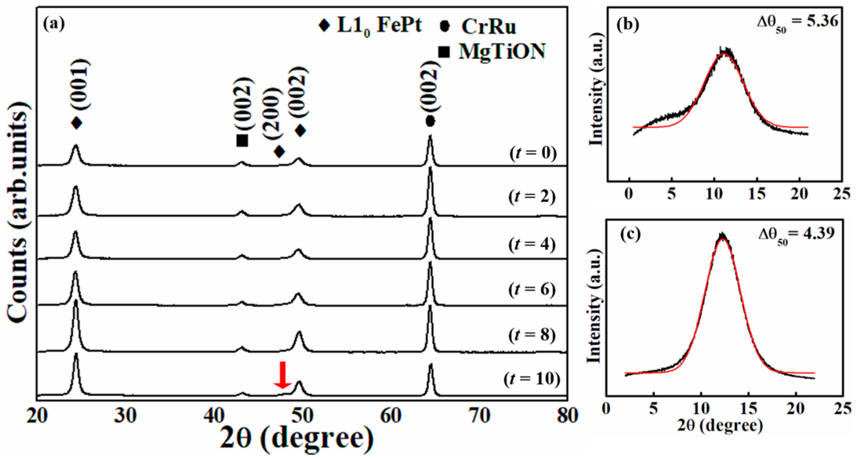
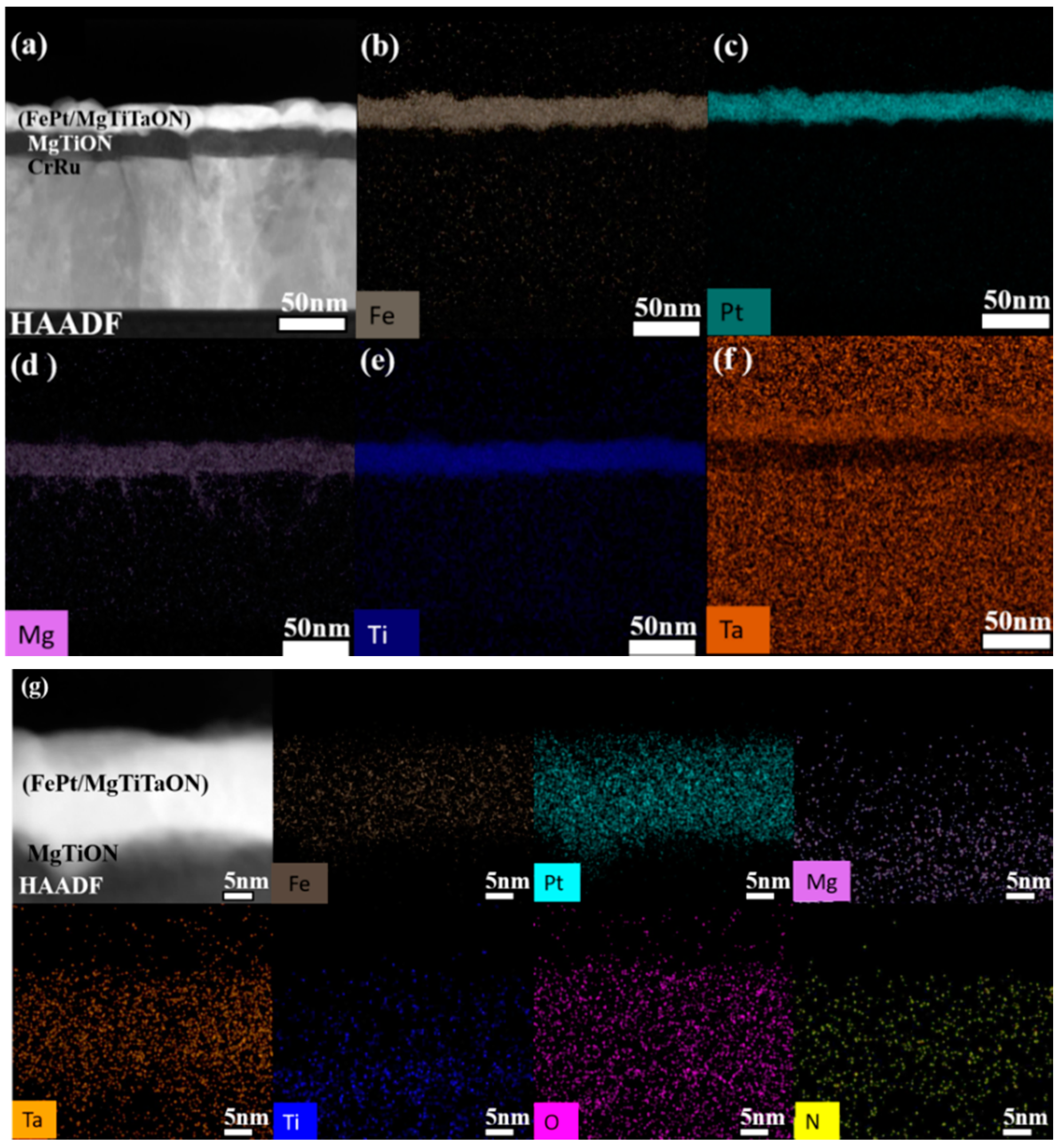
3.1. FePt(t nm)/[MgTiTaON(1 nm)/FePt(4 nm)]2/MgTiON/CrRu (t = 0, 2, 4, 6, 8, 10) Films

Figure 1 shows the XRD pattern of the FePt(t nm)/[MgTiTaON(1 nm)/FePt(4 nm)]2/MgTiON/CrRu (t = 0, 2, 4, 6, 8, 10) films. The (002) reflection peaks of the CrRu seed-layer and MgTiON intermediate-layer are presented and the (001) superlattice and (002) fundamental reflection peaks of L10 FePt phase are indexed. The (002) textured seed/intermediate-layers were confirmed to promote the formation of FePt phase with a (001) crystallographic orientation. The degree of preferential growth along the c-axis of FePt layer was estimated by measuring the full width at half maximum (FWHM) of the rocking curve of the FePt (001) peak in Figure 1a. The rocking width (Δθ50) for sample t = 0, 6, and 10 nm are 5.36°, 4.55° in Figure 3b, 4.39°, respectively. The interleved MgTiTaON layers were also suggested to mantain the FePt (001) texture up to a total thickness of 18 nm and the c-axis of the FePt layer was almost oriented perpendicular to the film surface. Figure 2a illustrates the variation of saturation magnetization (Ms), out-of-plane coercivity (Hc) and nucleation filed (Hn) with total FePt thickness for series (I) samples. The FePt films show perpendicular magnetization with small in-plane hysteresis contribution. In Table 1, increasing the FePt thickness (t = 0 to 2, 4, 6, 8, 10) leads to the decrease of the out-of-plane coercivity Hc from 12.4 to 8.6, 8.6, 9.0, 5.8, and 6.7 kOe, respectively, and the FePt film with a total thickness 14 nm (t = 6) shows a lower decrease. The smaller out-of-plane coercivity values measured in series (I), (t = 2–10 nm) with respect to reference sample (Hc, 12.4 kOe for t = 0 nm) could be attributed to a lower ordering degree and larger grains size. The variation of nucleation fields with total FePt thickness also show a similar trend but different at t = 6–10 in Figure 2a. For t = 0 nm, the FePt film shows much lower saturation magnetization and t = 2–10 nm, the Ms in FePt films decrease with thickness which were attributed to the compositional interface (MgTiTaON) during high temperature deposition and uncertain interface dead layers. The FePt chemical ordering degree was estimated by measuring the [I(001)/I(002)]1/2 ratio [19,20], where I(001) and I(002) are the integrated intensities of the FePt (001) and (002) diffraction peaks. Increasing the FePt thickness (t = 0 to 2, 4, 6, 8) leads to a slight decrease of I(001)/I(002) shown in Figure 2b from 2.02 to 1.86, 1.92, 1.92, 1.90 thus indicating that the FePt ordering degree slightly decreases with the FePt total thickness. For t = 10, the FePt ordering degree increases (I(001)/I(002)~2.2) but also shows the variant (200) ordered or disordered FePt peak in Figure 1a. The diffraction peak around 49.06° in Figure 1 (t = 10) is the convolution of the Bragg peaks of the (200) fcc (at 47.75°) and (002) L10 (at 49.27°) phases, and the in-plane anisotropy was due to the contribution of disordered soft magnetic fcc phase [21]. As a result, the FePt film (t = 10) has a larger in-plane magnetization area (more misalign FePt grains) in Figure 2d as compared to the FePt film in Figure 2c (t = 0). In Figure 2b, the variation of lattice constant c estimated by FePt (001) peak also illustrates a similar trend regarding thickness.
When the growth of FePt film reaches the critical thickness, lattice relaxation was occurred via the formation of dislocations at the interface [22]. The lattice relaxation was caused the misalighment of FePt c-axis, increased the in-plane magnetization and deteriorated the perpendicular magnetic anisotropy [21]. In this study, the interleaved MgTiTaON layer was evidenced to maintain the FePt (001) orientation. However, the lattice relaxation phenomena still occurred when the thickness of FePt increased. The varient (200) tiny peak appeared to misalign the c-axis of FePt grains away from out-of-plane, and the ordering degree was also decreased with the FePt thickness. As results, the in-plane magnetization was increased and the perpendicular magnetic anisotropy was deteriorated. The out-of-plane Hc and nucleation field (Hn) were lower than the reference sample (t = 0 nm). The out-of-plane Hc was not high enough because of the reorientation of the perpendicular magnetic anisotropy of [FePt/MgTiTaON] film towards the in-plane direction due to the decrease of chemical ordering parameter evidenced in Figure 1 [21]. The hard/soft (fct/fcc) FePt composite film was exchange-coupled and lower the out-of-plane coercivity [21]. The sample (t = 6 nm, reference in series II) shows higher Hc, Hn and lower Ms in Table 1 in addition to sample (t = 0 nm). The Hc and Hn were influenced by FePt grains morphology and uniformity and lower Ms may due to a less disordered FePt phase.

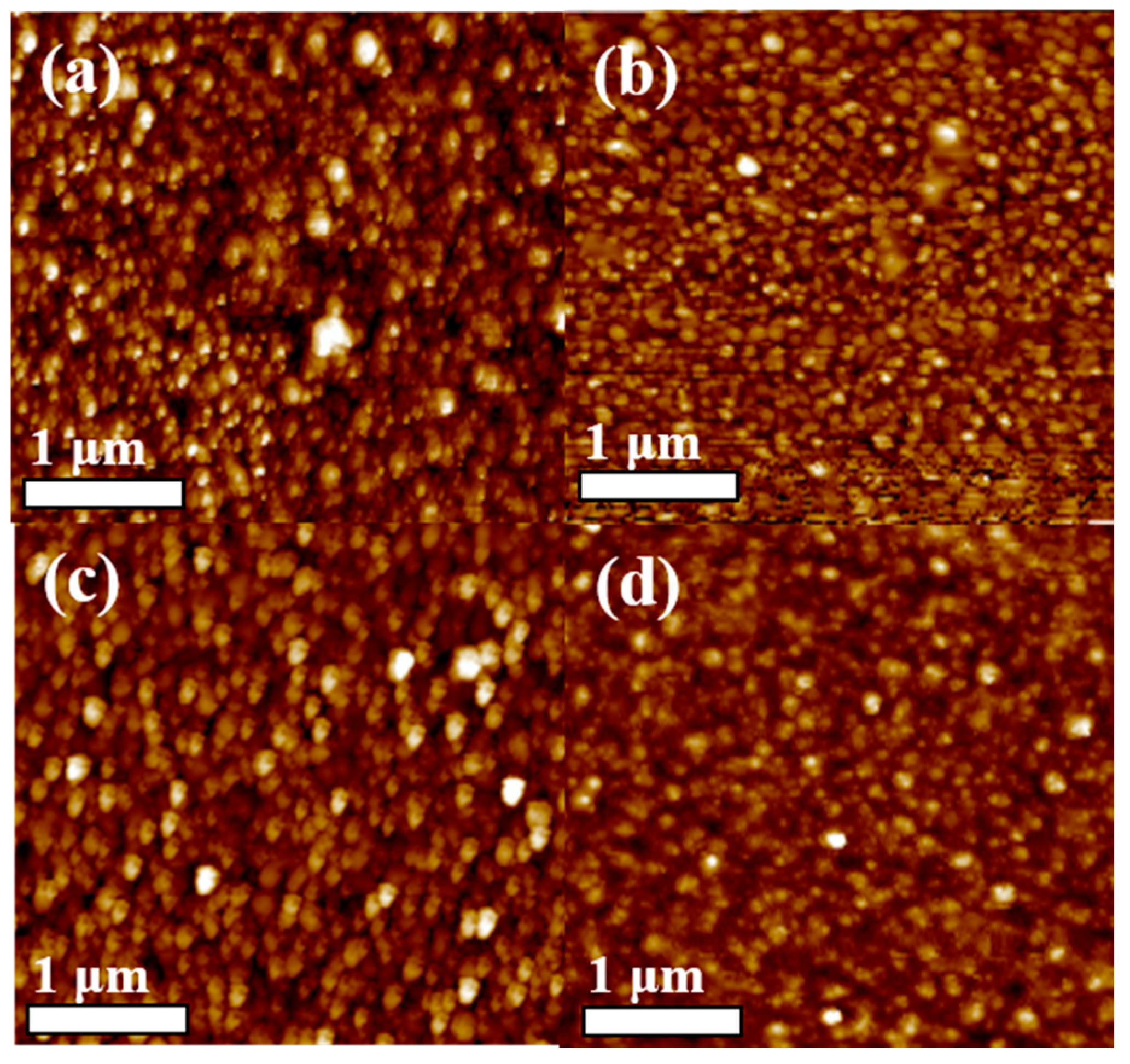
3.2. FePt(6 nm)(Ag,C)(x vol %)/[MgTiTaON(1 nm)/FePt(4 nm)(Ag,C)(x vol %)]2 (x = 0, 10, 20, 30, 40)

The 14-nm thick FePt film (t = 6 nm) was selected from series (I) and the (Ag, C) segregants were co-sputtered with FePt during deposition and the layer stacks in series (II) were FePt(6 nm)(Ag,C)(x vol %)/[MgTiTaON(1 nm)/FePt(4 nm)(Ag, C)(x vol %)]2 (x = 0, 10, 20, 30, 40) and the XRD spectra and represented rocking curves of series (II) are reported in Figure 3a. In addition to the (002) reflection peaks of the CrRu seed-layer and the MgTiON intermediate-layer, the (001) superlattice diffraction peak and the (002) fundamental reflection of the L10 FePt are present suggesting that the L10 FePt film has maintained a (001) preferred orientation with (Ag, C) segregants. The degree of preferential growth along the c-axis of the FePt layer was estimated by measuring the Full width at half maximum (FWHM) of the rocking curve of the FePt (001) peak in Figure 3. As compared to the 14-nm thick FePt single layer, the MgTiTaON inserted layer was slightly deteriorated the FePt ordering degree and perpendicular magnetic anisotropy. In Table 2, the sample (x = 0, t = 6 nm) presents lower ordering degree [I(001)/I(002) =1.95 < 2.14], out-of-plane Hc (9.0 <11.0 kOe), and nucleation field Hn (−2.94 < −3.21 kOe). The FePt grains were more separated and ordered after doping of (Ag, C) segregants and the Hc was increased with segregant concentrations.
Experimental values of 4.55° (Figure 3b), 5.83°, 6.68°, 4.84°, 4.62° (Figure 3c), 6.01° were measured, respectively. The FePt(Ag, C)(x = 20, 30 vol %) grains’ easy-axes are more or less misaligned as compared to the reference (FePt 14 nm) and x = 0 samples, respectively. The MgTiTaON layer slightly deteriorated the orientation which was improved by the suitable (Ag, C) segregants. The corresponding FePt chemical ordering degree was proportional to the I(001)/I(002) ratio, where I(001) and I(002) are the integrated intensities of the FePt (001) and (002) diffraction peaks. Increasing the content of (Ag, C) segregants leads to a gradual increase of I(001)/I(002) from 1.92 to 2.54, thus, indicating that the FePt ordering degree increases with the increase of (Ag, C) segregants volume concentration. Figure 4 reports on the out-of-plane and in-plane field-dependent magnetic hysteresis loops of representative samples of series (II) measured at room temperature. In Figure 4a, the out-of-plane coercivity of reference sample FePt(14 nm)/MgTiON/CrRu is 10.3 kOe. Increasing the (Ag, C) volume concentration to (20, 30, 40 vol %) leads to the increase of the out-of-plane coercivity Hc from 9.00 kOe (Figure 4b) to 13.6, 14.6 and 18.3 kOe in Figure 4d,f, respectively. However, the misaligned FePt grains (in-plane magnetization hysteresis contribution) also increases with segregants concentrations. The larger out-of-plane coercivity values measured in series (II), (Ag, C, (20–40 vol %) with respect to samples series (II) (0 vol %) could be attributed to a higher ordering degree, and more separated FePt grains. Figure 5 shows the plan-view, cross-section TEM images and surface roughness of reference sample, FePt(14 nm)/MgTiON/CrRu.
In Figure 5a, the FePt film is a continuous-like layer from a cross-sectional image and (b) is the selected area diffraction (SAD) pattern. The in-plane FePt grains are connected in the worm-like structure evidenced in-plane view TEM image illustrated in Figure 5c. The average surface roughness measured by AFM is 1.99 nm as shown in Figure 5d. Figure 6 shows the plan-view and cross-section TEM images of representative samples from series (II). In Figure 6a, the FePt grains are connected in the worm-like structure. The FePt grains are coalescence in island-like structure with 10 vol % (Ag, C) segregants shown in Figure 6b. The FePt gains are aggromolated and formed the large separated island which containes many FePt grains isolated by (Ag, C) in Figure 6c,d. In our previous work [16,17,18], the FePt film deposited on the MoC layer always forms the big trapezoidal islands due to the excess carbon diffused up to separate part of the FePt grains and each island contains many interacted FePt grains observed in Figure 7c,d in reference [17]. During deposition at high temperature, the FePt grains were separated laterally by (Ag, C) due to high phase separation ability of carbon and MgTiTaON interlayer was used to maintain the epitaxial growth. As a result, the FePt grain was grown perpendicular to the film plane and limited in the lateral direction and tall square-like FePt island (31–38 nm in height) were obtained. The average FePt island height was larger than twice of original deposition thickness (14 nm). In Figure 6e, the FePt islands are separated uniformly in dense columnar-like morphology with the increase of (Ag, C) (40 vol %) segregant. The in-plane grains in Figure 6f,g are separated and the grains size decreasing from 10.5 ± 2.31 nm to 6.47 ± 3.39 nm with the increase in the segregant volume concentration.
High-angle annular dark field (HAADF) analysis, which provides an atomic number (Z)-dependent contrast, was used to map the distribution of the different elements within the stack of FePt(6 nm)/[MgTiTaON(1 nm)/FePt(4 nm)]2/MgTiON layers and all the elements are visible in Figure 7a–f. From the magnified HAADF images in Figure 7g, the Ta, Mg, O, N in MgTiTaON interlayer were diffused into all the FePt magnetic layer during high temperature deposition. This result clearly explained the lower ordering degree and out-of-plane coercivity for FePt film with an MgTiTaON interlayer (Hc 9.00 kOe) as compared to the reference sample (14 nm FePt, Hc 10.3 kOe). Based on references [6,7], the second nucleated FePt layer occurred in FePtC film when the thickness was higher than 6 nm and a thin MgTiTaON interlayer was truly promoting the formation of highly FePt square- and columnar-like structure with island tall in the range of 31–38 nm. The different morphology observed in series (II), also reflects in a different surface roughness, as determined from the AFM images (Figure 8), which is overall larger for samples of series (II) (2.38 nm, 4.16 nm, 5.28 nm and 3.25 for (Ag, C), 10, 20, 30, 40 vol %, respectively) with respect to the reference sample from Figure 5d (1.99 nm).

4. Conclusions

The [FePt(Ag, C)/MgTiTaON] multilayer was translated to the FePt(Ag, C, MgTiTaON) granular structure after a high deposition temperature. The FePt grains were separated by (Ag, C) segregants and grew upward by an MgTiTaON thin layer. Finally, anomalous taller FePt islands (31–38 nm) with the square- and columnar-like morphology were obtained. The MgTiTaON interlayer with suitable lattice misfit favors the c-axis orientation and maintain the Ku of FePt film. The fabrication method to have microstructure with taller and separated FePt islands was provided in this study.

Author Contributions

J.-L.T. was designed the experiments, analyzed the data and paper writing; C.D. and S.-M.W. were performed the sample preparation experiments; T.-W.H., J.-y.C. and L.-C.H. were performed the microstructure and surface investigation.

Funding

This research was funded by Ministry of Science and Technology, Taiwan, the grant number [MOST 107-2221-E-005-011.], Solar Applied Materials Technology Corp., Taiwan, the grant number [107D520].

Acknowledgments

The authors would like to thank for Solar Applied Materials Technology Corp. for sputtering targets support.

Conflicts of Interest

The authors declare no conflict of interest. The founding sponsors had no role in the design of the study; in the collection, analyses, or interpretation of data; in the writing of the manuscript, and in the decision to publish the results.

References

  1. Hono, K.; Takahashi, Y.K. L10 FePt Granular Films for Heat-Assisted Magnetic Recording Media. In Ultrahigh Density Magnetic Recording; Varvaro, G., Casoli, F., Eds.; Pan Stanford Publishing: Singapore, 2016; pp. 246–277. [Google Scholar]
  2. Weller, D.; Parker, G.; Mosendz, O.; Lyberatos, A.; Mitin, D.; Safonova, N.Y.; Albrecht, M. Review Article: FePt heat assisted magnetic recording media. J. Vac. Sci. Technol. B 2016, 34, 060801. [Google Scholar] [CrossRef]
  3. Weller, D.; Mosendz, O.; Parker, G.; Pisana, S.; Santos, T.S. L10 FePtX–Y media for heat-assisted magnetic recording. Phys. Status Solidi A 2013, 210, 1245–1260. [Google Scholar] [CrossRef]
  4. Ju, G.P.; Peng, Y.G.; Chang, E.K.C.; Ding, Y.; Wu, A.Q.; Zhu, X.; Kubota, Y.; Klemmer, T.J.; Amini, H.; Gao, L.; et al. High density heat-assisted magnetic recording media and advanced characterization—Progress and challenges. IEEE. Trans. Magn. 2015, 51, 3201709. [Google Scholar] [CrossRef]
  5. Futamoto, M.; Ohtake, M. Development of media nanostructure for perpendicular magnetic recording. J. Magn. Soc. Jpn. 2017, 41, 108–126. [Google Scholar] [CrossRef]
  6. Zhang, L.; Takahashi, Y.K.; Perumal, A.; Hono, K. L10-orderedhighcoercivity(FePt)Ag–C granular thin films for perpendicular recording. J. Magn. Magn. Mater. 2010, 322, 2658–2664. [Google Scholar] [CrossRef]
  7. Shiroyama, T.; Varaprasad, B.S.D.C.S.; Takahashi, Y.K.; Hono, K. Microstructure and magnetic properties of FePt–Cr2O3 films. IEEE. Trans. Magn. 2014, 50, 3202404. [Google Scholar] [CrossRef]
  8. Deng, J.Y.; Dong, K.F.; Peng, Y.G.; Ju, G.P.; Hu, J.F.; Chow, G.M.; Chen, J.S. Effect of TiON-MgO intermediate layer on microstructure and magnetic properties of L10 FePt-C-SiO2 films. J. Magn. Magn. Mater. 2016, 417, 203–207. [Google Scholar] [CrossRef]
  9. Li, H.H.; Dong, K.F.; Peng, Y.G.; Ju, G.P.; Chow, G.M.; Chen, J.S. Microstructures and magnetic properties of FePt thin films on TiON intermediate layer. IEEE. Trans. Magn. 2014, 50, 3201007. [Google Scholar] [CrossRef]
  10. Yang, E.; Ho, H.; Laughlin, D.E.; Zhu, J.G. Columnar grain growth of FePt(L10) thin films. J. Appl. Phys. 2012, 111, 07B720. [Google Scholar] [CrossRef]
  11. Hellwig, O.; Mosendz, O.; Weller, D. Layered Segregant Heat Assisted (52) Magnetic Recording (HAMR) Media. U.S. Patent 20160099017 A1, 7 April 2016. [Google Scholar]
  12. Dong, K.F.; Li, H.H.; Peng, Y.G.; Ju, G.P.; Chow, G.M.; Chen, J.S. NanocompositeL10 FePt–SiNx and FePt–SiNx–C films with large coercivity and small grain size on aTiN intermediate layer. J. Magn. Magn. Mater. 2012, 324, 2637–2644. [Google Scholar] [CrossRef]
  13. Zhang, Y.; Kalitsov, A.; Ciston, J.; Mryasov, O.; Ozdol, B.; Zhu, J.; Jain, S.; Zhang, B.; Livshitz, B.; Chernyshov, A.; et al. Microstructure and magnetic properties of ultrathin FePt granular films. AIP Adv. 2018, 8, 125018. [Google Scholar] [CrossRef]
  14. Rizal, C.; Fullerton, E.E. Perpendicular magnetic anisotropy and microstructure properties of nanoscale Co/Au multilayers. J. Phys. D Appl. Phys. 2017, 50, 355002. [Google Scholar] [CrossRef]
  15. Bersweiler, M.; Dumesnil, K.; Lacour, D.; Hehn, M. Impact of buffer layer and Pt thickness on the interface structure and magnetic properties in (Co/Pt) multilayers. J. Phys. Condens. Matter 2016, 28, 336005. [Google Scholar] [CrossRef] [PubMed]
  16. Tsai, J.L.; Tseng, Y.T.; Li, C.R.; Fu, S.C. Magnetization reversal process in Fe/FePt films. Appl. Phys. Lett. 2010, 96, 032505. [Google Scholar] [CrossRef]
  17. Tsai, J.L.; Tzeng, J.L.; Hu, K.C.; Li, H.K.; Pan, Z.Y.; Chang, Y.S.; Liao, C.C. Microstructure and magnetic properties of FePt film with combined MoC/(Mg–X)O (X = Cu, Ni,Co) intermediate layers. J. Magn. Magn. Mater. 2017, 422, 262–270. [Google Scholar] [CrossRef]
  18. Tsai, J.L.; Li, H.K.; Pan, Z.Y.; Chang, Y.S.; Chen, Y.R.; Pi, C.; Wu, Y.T.; Chang, C.W. Magnetic Properties and Microstructure of FePt Films With MgTiON Intermediate Layer. IEEE Trans. Magn. 2017, 53, 8108404. [Google Scholar] [CrossRef]
  19. Yang, E.; Laughlin, D.E.; Zhu, J.G. Correction of order parameter calculations for FePt perpendicular thin films. IEEE Trans. Magn. 2012, 48, 7–12. [Google Scholar] [CrossRef]
  20. Granz, S.D.; Kryder, M.H. Granular L10 FePt (001) thin films for heat assisted magnetic recording. J. Magn. Magn. Mater. 2012, 324, 287–294. [Google Scholar] [CrossRef]
  21. Kaidatzis, A.; Psycharis, V.; Giannopoulos, G.; Garcia-Martin, J.M.; Niarchos, D. Magnetic anisotropy axis reorientation at ultrathin FePt films. Phys. Status Solidi RRL 2016, 11, 1600386. [Google Scholar] [CrossRef]
  22. Li, H.H.; Dong, K.F.; Hu, J.F.; Zhou, T.J.; Chow, G.M.; Chen, J.S. Lattice relaxation and its impact on magnetic properties of FePt thin film. J. Phys. D Appl. Phys. 2013, 46, 015002. [Google Scholar] [CrossRef]
Figure 1. XRD of the FePt(t nm)/[MgTiTaON(1nm)/FePt(4nm)]2/MgTiON/CrRu, (a) t = 2–10 nm, Rocking curves of (b) t = 0 nm, and (c) t = 10 nm.
Coatings 09 00238 g001
Figure 2. The variation of (a) saturation magnetization (Ms), out-of-plane coercivity (Hc) and nucleation field (Hn); (b) I(001)/I(002) and lattice constant c with total FePt thickness for series (I) samples. Out-of-plane (- • -) and in-plane (- o -) field-dependent magnetization loops of FePt(t nm)/[MgTiTaON(1 nm)/FePt(4 nm)]2/MgTiON/CrRu, (c) t = 0 and (d) t = 10 films measured at room temperature.
Coatings 09 00238 g002
Figure 3. (a) XRD patterns of sample series (II), FePt(6 nm)(Ag, C)(x vol %)/[MgTiTaON (1 nm)/FePt(4 nm)(Ag, C)(x vol %)]2 (x = 0, 10, 20, 30, 40). Rocking curves of (b) reference sample (ref), and (c) x = 30.
Coatings 09 00238 g003
Figure 4. The out-of-plane (- • -) and in-plane (- o -) and in-plane field-dependent magnetic hysteresis loops of (a) reference sample FePt (14 nm), and sample series (II) FePt (6 nm)(Ag, C)(x vol %)/[MgTiTaON (1 nm)/FePt(4 nm)(Ag, C)(x vol %)]2; (b) x = 0; (c) x = 10; (d) x = 20; (e) x = 30; (f) x = 40.
Coatings 09 00238 g004
Figure 5. (a) cross-sectional TEM images; (b) SAD of (a); (c) plan-view; TEM images and (d) surface roughness of reference sample, FePt(14 nm)/MgTiON/CrRu film.
Coatings 09 00238 g005
Figure 6. Cross-section TEM images of representative samples from series (II), (a) x = 0; (b) x = 10; (c) x = 20; (d) x = 30; (e) x = 40; plan-view iamges of samples (f) x = 20; (g) x = 40.
Coatings 09 00238 g006
Figure 7. Element mapping of FePt(6 nm)/[MgTiTaON(1 nm)/FePt(4 nm)]2/MgTiON film, (a) Dark field image; (b–f) mapping image of (b) Fe; (c) Pt; (d) Mg; (e) Ti and (f) Ta; (g) magnified images of FePt/MgTiTaON layers.
Coatings 09 00238 g007
Figure 8. The surface roughness of samples series (II), FePt(6 nm)(Ag, C)(x vol %)/[MgTiTaON(1 nm)/FePt(4 nm)(Ag, C)(x vol %)]2 films, (a) 2.38 nm; (b) 4.16 nm; (c) 5.28 nm and (d) 3.25 for (Ag, C), x = 10, 20, 30, 40 vol %, respectively.
Coatings 09 00238 g008
Table 1. Out of plane Hc, nucleation field (Hn), saturation magnetization (Ms), Integrated intensity ratio (I(001)/I(002)), surface roughness (Ra) of FePt(t nm)/[MgTiTaON(1 nm)/FePt(4 nm)]2/MgTiON/CrRu films.
FePtHc⊥ (kOe)Hn (kOe)Ms (emu/cm3)I(001)/I(002)Ra (nm)
t = 0 nm12−7.4587.02.015.31
t = 2 nm8.7−1.213461.86
t = 4 nm8.6−0.911371.91
t = 6 nm9.0−2.4872.01.952.83
t = 8 nm5.8−2.810271.90
t = 10 nm6.7−1.510562.12
Table 2. Out-of-plane Hc, nucleation field (Hn), saturation magnetization (Ms), Integrated intensity ratio (I(001)/I(002)), surface roughness (Ra) of reference sample FePt (14 nm), and sample series (II) FePt(6 nm)(Ag,C)(x vol %)/[MgTiTaON (1 nm)/FePt(4 nm)(Ag,C)(x vol %)]2; (b) x = 0; (c) x = 10; (d) x = 20; (e) x = 30; (f) x = 40.
FePt (Ag, C)Hc (kOe)Hn (kOe)Ms (emu/cm3)I(001)/I(002)Ra (nm)
FePt (14 nm)11.03.218242.143.43
x = 0 (t = 6 nm)9.002.948721.952.83
x = 108.700.836422.503.08
x = 2014.07.068662.305.32
x = 3014.65.919532.307.41
x = 4018.34.697022.505.77

