Article

Microstructure and Properties of M3B2-Type Boride-Based Cermet Coatings Prepared by Laser Cladding Synthesis

Merchant Marine College, Shanghai Maritime University, Shanghai 201306, China
*
Authors to whom correspondence should be addressed.
Coatings 2019, 9(8), 476; https://doi.org/10.3390/coatings9080476
Submission received: 2 July 2019 / Revised: 25 July 2019 / Accepted: 25 July 2019 / Published: 28 July 2019

Abstract

:
Although Q235 steel materials are widely used in offshore engineering, the service life is severely shortened by its inferior resistance to wear and corrosion in harsh marine working environments. Boride-based cermet composites could be a good surface-protective coating to enhance surface hardness, wear resistance, and corrosion resistance. M3B2 (M: Mo, Ni, Fe, Cr) boride-based cermet coatings composed of hard ceramics of M3B2-type complex borides and an {Fe, Ni} metal matrix was fabricated on Q235 steels with mixed Mo, Cr, B, and Ni60 powders using a laser cladding synthesis technique. The influences of laser cladding parameters on the microstructure, phase composition, microhardness, and corrosion resistance of the coatings were comprehensively investigated. Results showed that the microstructures of the coatings mainly consisted of three layers, which were, from the top to bottom layer, a metal layer with fewer ceramic phases, a ceramic layer with fewer metal phases, and another metal layer with fewer ceramic phases. The ceramic phases were mainly M3B2-type borides, and the metal phases were mainly {Fe, Ni} alloys. The appearance of Fe-enriching metal phases was due to the supply of Fe elements from Q235 substrates. With squash pretreatment and without a remelting aftertreatment, ceramics uniformly dispersed in the cermet coatings, and their sizes decreased. The results of microhardness showed that the microhardness of the coating first increased and then decreased from the top layer to the bottom layer, and maximum microhardness was obtained in the layer of ceramics with less metal phases. An electrochemical corrosion test showed that the cermet coatings (jcorr = 6.35 μA/cm2) could improve the corrosion resistance of Q235 steels (j = 43.76 μA/cm2) by one order of magnitude.

1. Introduction

Because of its superior properties, such as high strength, plasticity, and weldability, Q235 steel materials are widely used in the fields of offshore engineering and offshore facilities [1]. However, in harsh marine working conditions, such as high humidity, wear, scour, and corrosion, the service life of Q235 steels is severely shortened because of its inferior resistance to wear and corrosion [2]. To maintain the effective service life of Q235 steels, surface-protective coatings need to be prepared on Q235 steels to enhance the surface hardness, wear resistance, and corrosion resistance.
Boride-based cermet composite coatings consist of a transition metal base matrix with dispersed hard phases, such as TiB2, Mo2FeB2, and Mo2NiB2, and they possess high hardness, high melting point, good wear and corrosion resistance, and good optical and thermal properties [3,4,5,6,7,8]. These cermet coatings have already been applied to wear- and corrosion-resistant applications such as injection molding machine parts, bearings for sea water pumps, and offshore engineering parts [9]. In particular, as emerging and promising materials with superior strength, hardness, and wear and corrosion resistance, M3B2-type boride-based cermet coatings such as Mo2FeB2, Mo2NiB2, and W2NiB2 as hard phases, are qualified candidates for applications in wear and corrosion resistance [10,11]. Takagi et al. [12] found that M3B2 (Mo2FeB2 and Mo2NiB2)-based cermet coatings possessed excellent hardness and bonding properties, wear resistance, and corrosion resistance. Yuan et al. [13] prepared Mo2NiB2 cermets and found that the maximum bending strength and hardness of Mo2NiB2 cermets reached 1.85 ± 0.04 GPa and 85.7 ± 0.1 HRA, respectively. The addition of Cr powders enhanced the hardness, transverse rupture strength (TRS), and elastic modulus of Mo2NiB2-based cermets [14]. Yu et al. [15] fabricated Mo2FeB2-based cermets and found the cermets with the highest TRS, hardness, and fracture toughness. Yu et al. [16] found that preparation temperatures could optimize the microstructure, consequently enhancing the mechanical property of the coating. Thus, M3B2-based cermet coatings can excellently fulfill resistant roles to the wear and corrosion of Q235 steels, consequently widening the applications of Q235 steels.
With respect to the fabrication techniques of M3B2 cermet coatings, several surface modification methods can be taken advantage of, such as high-velocity oxy-fuel (HVOF), detonation gun spraying, electrospark deposition, flame spraying, vacuum powder sintering, plasma spraying, and laser surface cladding [17,18,19,20,21,22,23]. These methods can provide a lot of energy for the reactive synthesis of M3B2 cermet coatings. Nonetheless, each method has its own characteristics (merits and drawbacks) so that the prepared coatings can have a diverse microstructure and properties. Among these fabrication methods, the laser surface cladding technique possesses some advantages over other methods, such as its convenience, high efficiency, high energy, cost effectiveness, and the fact that it is environmentally friendly [24]. Furthermore, laser surface cladding can contribute to the establishment of a metastable phase induced by high cooling rates (103 to 108 K/s), novel properties that conventional methods cannot produce, artificial controllability of properties by varying the process variables, and metallurgical bonding strength between coatings and substrate [25]. Thus, the laser surface cladding technique has been utilized to prepare M3B2 cermet coatings. Wu et al. [26] found that continuous, dense, and adherent M3B2 cermet coatings could be obtained by a laser surface cladding technique. Also, the laser-clad M3B2 cermet coatings exhibited high hardness and good wear and corrosion resistance. However, related research about the preparation and characterization of M3B2 by laser surface cladding is quite scant. Lots of work should be carried out to investigate the laser cladding process and characterization of the microstructure and properties of M3B2 cermet coatings, which are complex but very important and meaningful for the preparation and application of M3B2 cermet coatings.
In the present paper, M3B2 cermet coatings were prepared on Q235 using a laser cladding synthesis technique. The influence of the laser cladding process, including pretreatments and aftertreatments on the microstructure and phase composition of M3B2 cermet coatings, was investigated. The microhardness distribution along the depth of coatings and the corrosion resistance of coatings were also evaluated. The microhardness of the coating was measured by a Vickers hardness tester. The corrosion resistance of coatings was evaluated by an electrochemical workstation (Autolab PGSTAT302N). Corrosion potential and corrosion current were obtained by the Tafel extrapolation method. Electrochemical impedance spectra (EIS) made up of Nyquist and Bode plots were measured. The maximum mean microhardness was 1700 HV. The lowest corrosion current of coatings was 6.35 μA.

2. Materials and Methods

2.1. Preparation of M3B2-Based Cermet Coatings

M3B2-based cermet coatings were prepared with Mo, Ni60, Cr, and B mixed powders by the laser cladding technique. The average size of all powders was 45 μm. The composition of mixed powders is listed in Table 1. The substrate materials were Q235 steels (C 0.14–0.22%, Mn 0.3–0.65%, Si ≤ 0.3%, S ≤ 0.05%, and P ≤ 0.045%) with a size of 80 mm × 100 mm × 8 mm.
Before the laser cladding process, Q235 substrates were sandblasted for 10 min to remove rust oil, then they were cleaned with alcohol. Mo, Ni60, Cr, and B powders were mixed and ball milled for 2 h. During the laser cladding process, a Laserline 4000–100 laser was used for the laser source, and the wavelength of the laser was 1080 nm with a laser spot diameter of 5 mm. Two different powder pretreatment methods, including polyvinyl butyral (PVB) binder presetting and squash presetting, and two different aftertreatment methods, including remelting and no remelting, were used to investigate their influences on M3B2-based cermet coatings in this experiment. Detailed laser cladding parameters are given in Table 2, and the production process of M3B2-based cermet coatings is exhibited in Figure 1. After preparation, the coated specimens were cut into small specimens of 10 mm × 10 mm for further characterization.

2.2. Characterization of M3B2-Based Cermet Coatings

The microstructure and composition distribution of the M3B2-based cermet coatings were characterized by scanning electron microscopy (SEM, Hitachi TM3030, Tokyo, Japan) and energy-dispersive X-ray spectroscopy (EDS, Oxford Swift 3000, Oxford, UK). The phase composition of specimens was analyzed by X-ray diffraction (XRD, Rigaku Ultima IV, Tokyo, Japan) with Cu-Kα radiation (λ = 1.54 A) operated at 40 kV and 20 mA. The 2θ angle was detected from 20° to 100°.
The square cross-sections were rubbed by finer and finer sandpaper, then they were polished with a polishing cloth. Microhardness of the boride-based composite coating was measured by a Vickers hardness tester (HXD-1000TMC/LCD, Shanghai TaiMing, Shanghai, China) with a load of 100 gf for a dwell time of 15 s.
The corrosion resistance of the M3B2-based cermet coatings was evaluated by an electrochemical workstation (Autolab PGSTAT302N) in 3.5 wt % NaCl solution at 25 °C. A standard three-electrode system was used. The reference electrode was a silver chloride electrode (Ag/AgCl), the counter electrode was platinum, and the working electrode coated specimens with a surface area of 1 cm2. The open circuit potential (OCP) was measured for 1 h. Potentiodynamic polarization experiments were scanned at 1 mV/s in the range of OCP ± 0.8 V, and corrosion potential (Ecorr) and corrosion current (Icorr) were obtained by the Tafel extrapolation method. The electrochemical impedance spectra (EIS) made up of Nyquist and Bode plots were measured at OCP with a potential amplitude of 5 mV and a frequency of 0.01 to 100,000 Hz. Prior to each corrosion experiment, the coatings were immersed in 3.5 wt % NaCl solution for 1.5 h.

3. Results

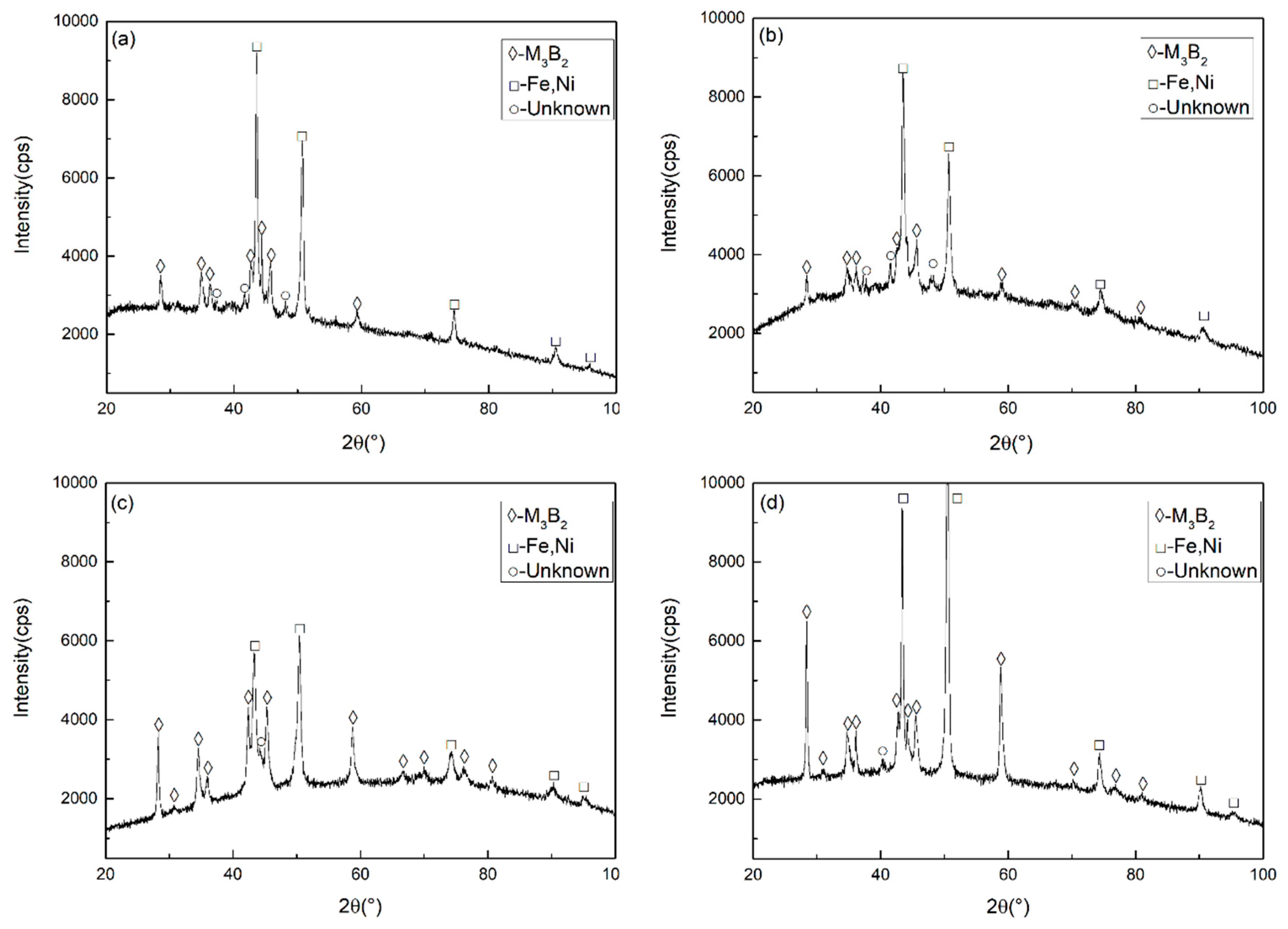
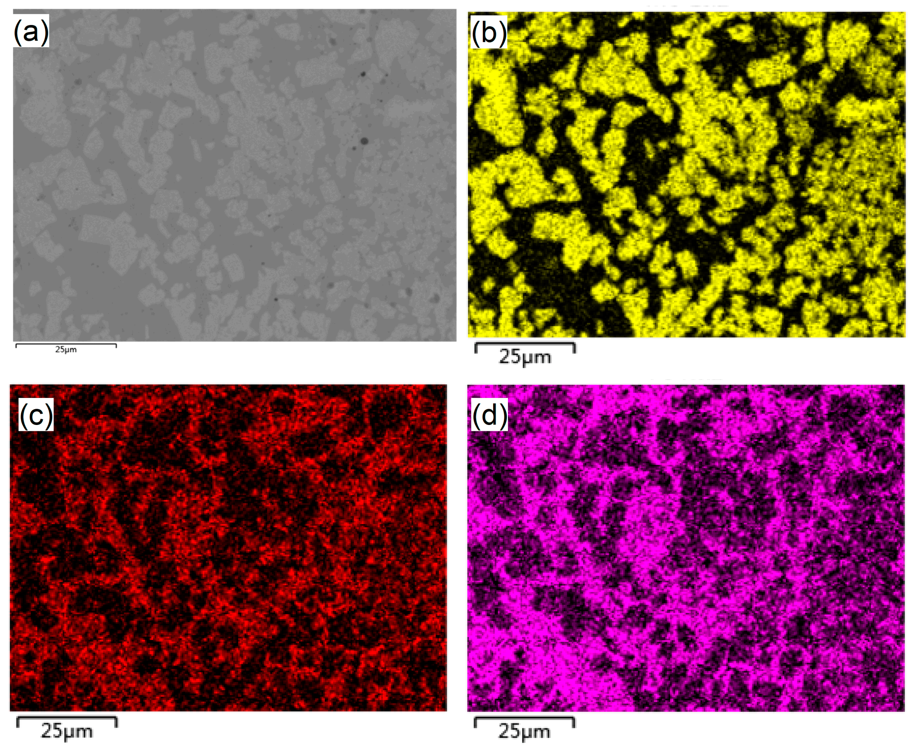
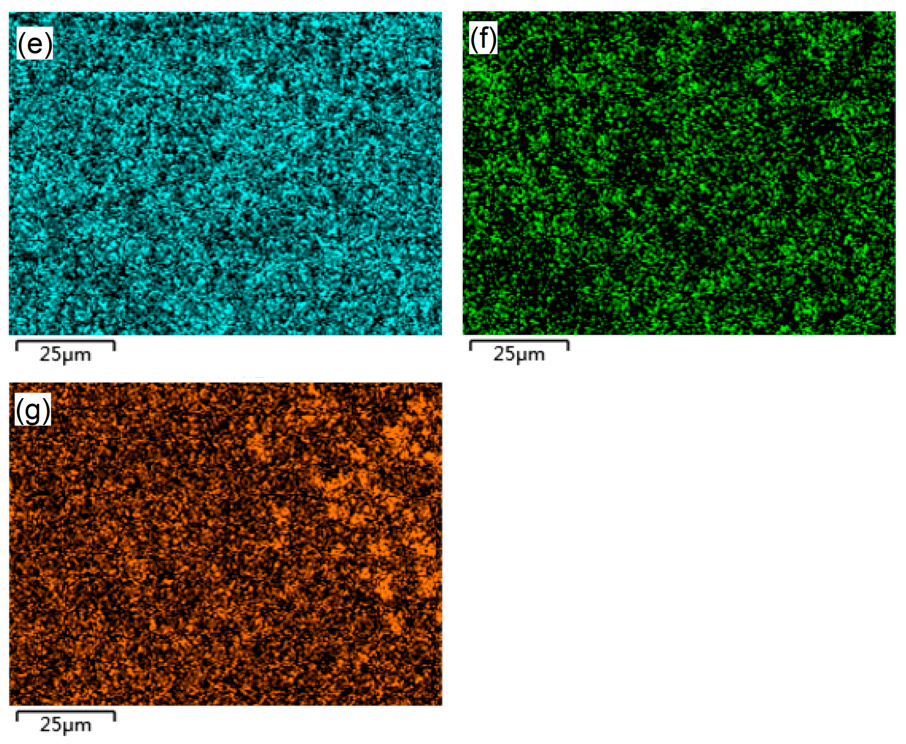
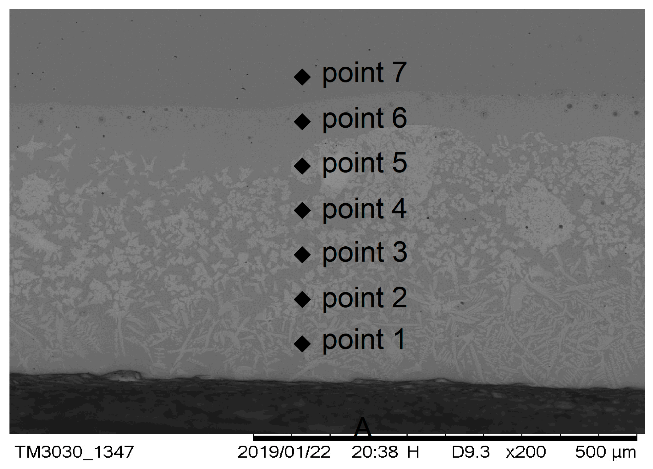
3.1. Microstructure and Composition of M3B2-Based Cermet Coatings
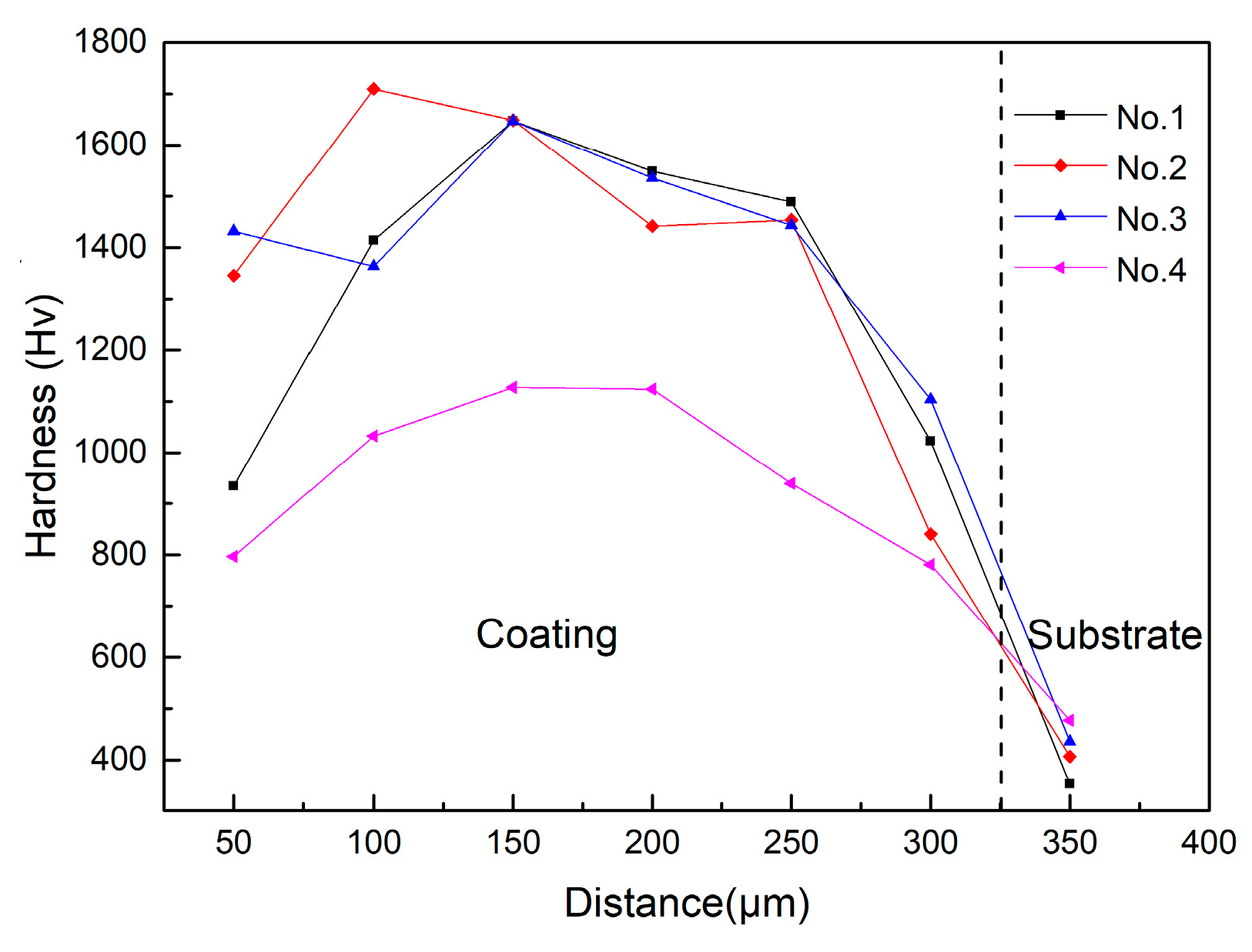
The XRD patterns of M3B2-based cermet coatings are shown in Figure 2. Results indicate that all samples consisted of the (M2M)3B2 (M: Mo, Ni, Cr, Fe) complex boride phase and the {Fe, Ni} phase. The boride phase, M3B2, was synthesized by laser cladding.
The diffraction peak intensity of the {Fe, Ni} phase was very strong, as shown in Figure 2d, and this gradually decreased in Samples 1 and 3. The diffraction peak intensity of the M3B2 phase showed no obvious differences between Samples 1 and 2, but it was stronger in Samples 3 and 4, as shown in Figure 2c,d compared to Figure 2a,b. The distribution of the phase in the four samples was different according to the SEM image in Figure 3, which was the major cause of the difference in intensity in the XRD patterns of the samples. The 10 mm × 10 mm surface of the coating was scanned by a Rigaku diffractometer. Two phases were found in the top layer of the three-layer coating, and the proportion of the phases were different, as shown in Figure 4. The {Fe, Ni} phase was richer in Sample 4, and the M3B2 phase was richer in Sample 3.
Microstructures of the samples are shown in Figure 3. White, light gray, and dark gray colored phases were found in all samples. The dark gray phase is the substrate Q235 steel. The other two phases were found in the coating, which was consistent with the XRD results. The cross-section in the coating, shown in Figure 3, took on a visible structure of stratification, with a large amount of the light-gray phase but less of the white phase in the top layer of the coating, more white phase and less light-gray phase in the middle layer of the coating, and more light-gray phase in the bottom layer of the coating. The white phase was dendritic in the top layer, and it was flocculent in the middle layer, shown in Figure 3a, which used a PVB binder presetting method. The flocculent white phase in the middle of the coating diffused to the surface and the binder interface, and the thickness became thicker after being remelted, as shown in Figure 3b. The thickness of the coating was much thicker when the squash presetting method was used, according to previous experiments which used the PVB binder presetting method with a maximum coating thickness of 0.8 mm. The stratification shown in Figure 3c,d is not obvious, as it is also shown in Figure 3a,b. The top and bottom layers were smaller than those present in coatings using the PVB binder presetting method. The microstructure of the coating using the squash presetting method was very uniform and fine. The white structure of the coating changed from square- to needle-shaped after it was remelted, the thickness increased, and the structure became very uniform.
The elemental map in Figure 5 shows the spatial distribution of elements in the coating by SEM with EDS. The elemental distribution of the white phase was composed of a large amount of Mo and less Fe, Ni, and B, whereas the light-gray phase contained large amounts of Fe and Ni. It is considered that the white phase was M3B2 and the light-gray phase was the {Fe, Ni} phase, which agrees with the XRD analysis.

3.2. Hardness

The micro Vickers hardness test point positions of the boride-based composite coatings are shown in Figure 6. Seven points were tested on the cross-section, and three group points of each sample were tested.
The average hardness data of three groups are shown in Figure 7. The results show that the trend of cross-section hardness in the four samples was identical. The hardness increased from the top layer of the coating to the middle layer of the coating, then it decreased towards the substrate. The presetting method and process parameters influenced hardness, although the same variation trend regarding hardness was observed in all samples. The mean hardness of Sample 1 was 1343 HV, and the maximum value reached was 1647 HV (in the middle layer). The mean hardness of Sample 3 was 1421 HV, and the maximum value reached 1647 HV in the middle layer. The squash method resulted in a harder coating compared to the PVB binder method. Remelting process technology was used in Samples 2 and 4. The hardness curves show that the hardness of Sample 2 was higher than that of Sample 1, whereas the hardness of Sample 4 was lower than that of Sample 3, indicating that the remelting process had a large effect on the hardness.

3.3. Corrosion tests

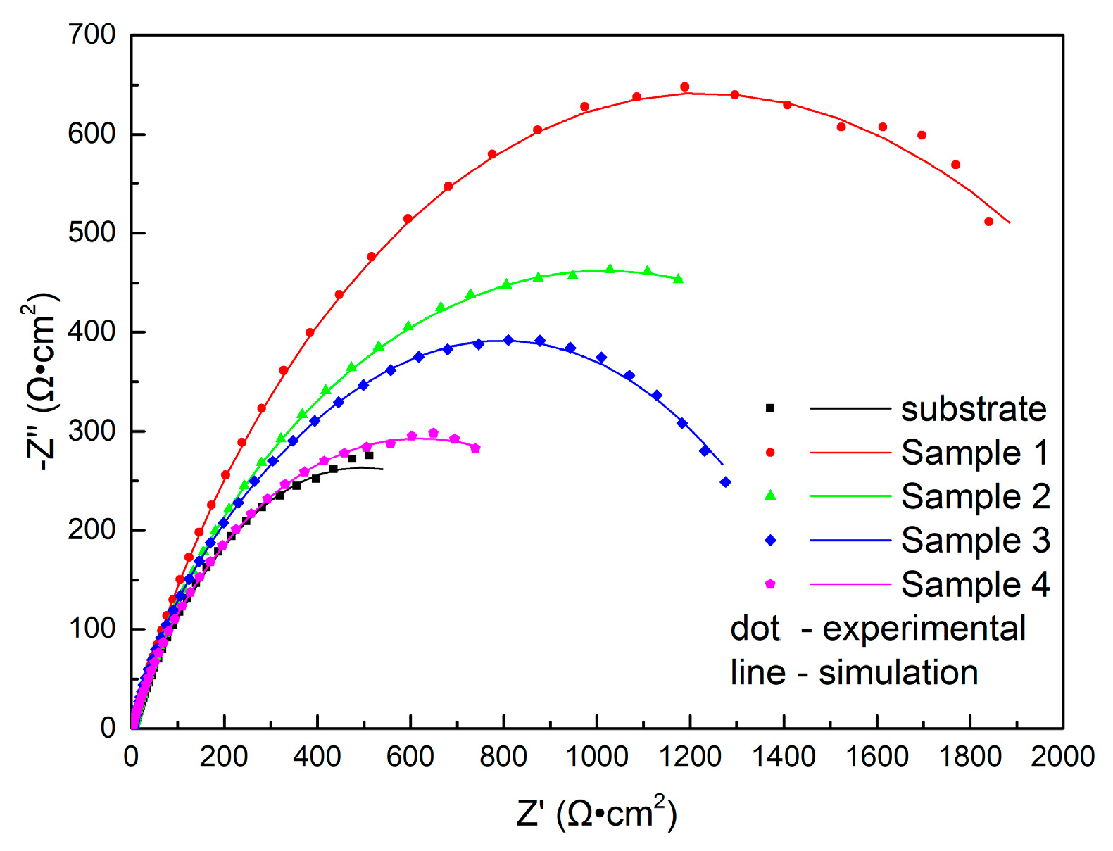
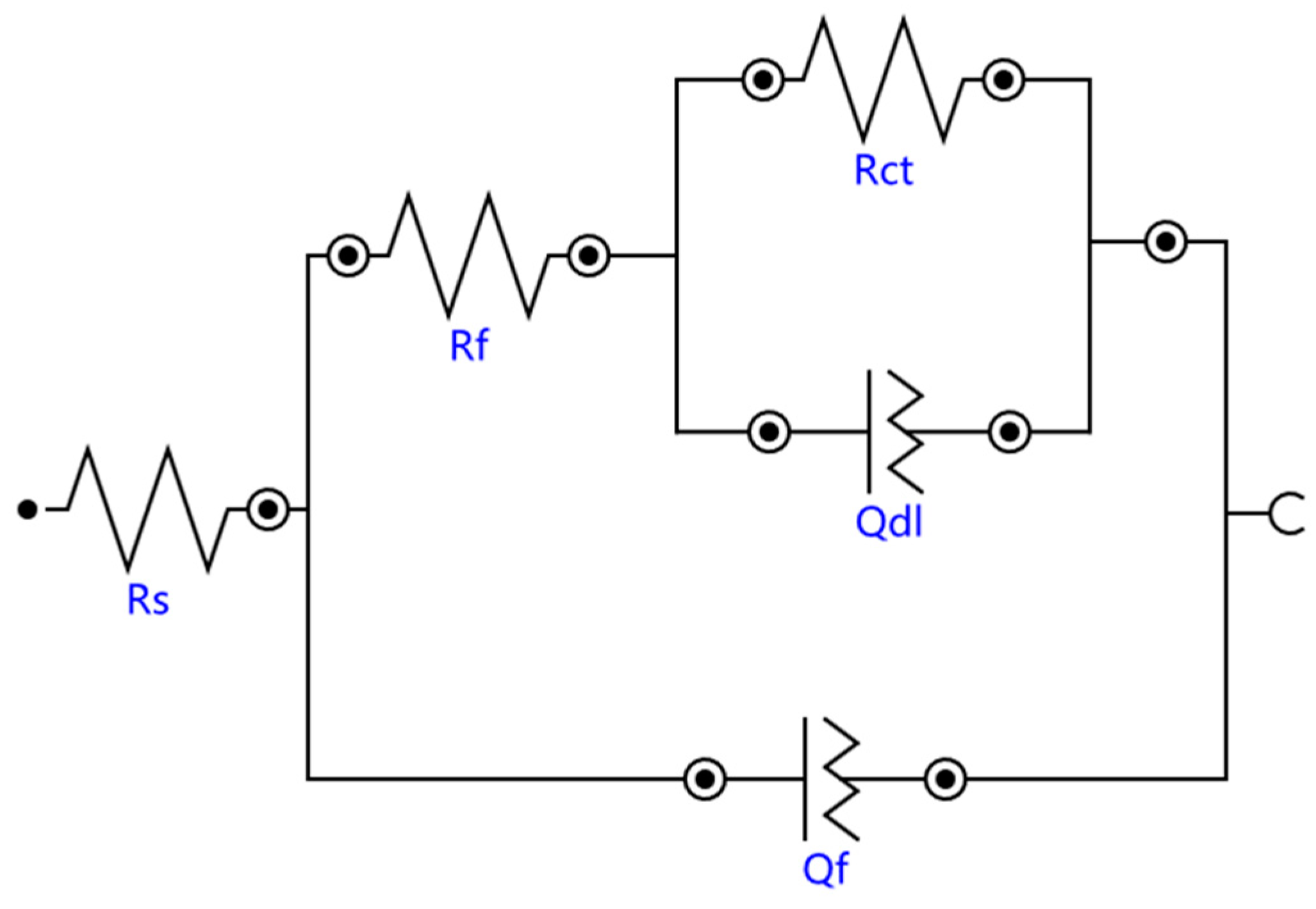
3.3.1. Electrochemical Impedance Spectroscopy

The EIS analyses of the substrate and the coatings of all samples are shown in Figure 8 and Figure 9. It can be seen that the Nyquist plots of samples formed a single capacitive reactance arc. The diameter of the capacitive reactance arc reflects the rate of the electrochemical reaction [27]. As the Nyquist plots in Figure 8 show, the diameter of the arc increased from substrate to the coating of Sample 1. This indicates that the corrosion resistance was improved by the coating, and the diameter arc was at its maximum when the PVB binder presetting was used without remelting.
The frequency-phase Bode plots of all samples are shown in Figure 9. They exhibited the same features as the Nyquist plots. The Z value was lowest for the substrate and highest in Sample 1 at the lowest frequency, which indicates that Sample 1 had the best corrosion resistance.
The equivalent circuit model shown in Figure 10 was used to fit the EIS data [28,29]; Rs is the solution resistance from the reference electrode to the working electrode, Rf is the surface layer resistance, and Rct is the constant phase elements of the charge transfer resistance. The impedance of the regular phase-angle element Q is related to the angular frequency (w) by the following relation: ZCPE = Y0−1(jw)n, where Y0 is a proportionality factor and n is the deviation parameter, which reflects the roughness of the surface; Qf is the constant phase angle element (CPE) between the solution and the surface, and Qdl is the CPE of the interface double layer between the solution and the matrix.
The fitting results of the EIS data of samples immersed in 3.5% NaCl solution with different processing parameters are listed in Table 3. It shows that Rs changed from 1.17 to 4.51 Ω·cm2, indicating that the environmental conductivity was relatively stable. Rf changed from 2.32 to 710 Ω·cm2, and Rct changed from 980 to 2460 Ω·cm2. The polarization resistance Rp (Rp = Rf + Rct) is used to evaluate the corrosion resistance of materials [30]: the greater the Rp value, the better the corrosion resistance. The Rp value of Sample 1 indicated that it had the best corrosion resistance of all the samples. The results are consistent with the previous analysis of the Nyquist and Bode plots.

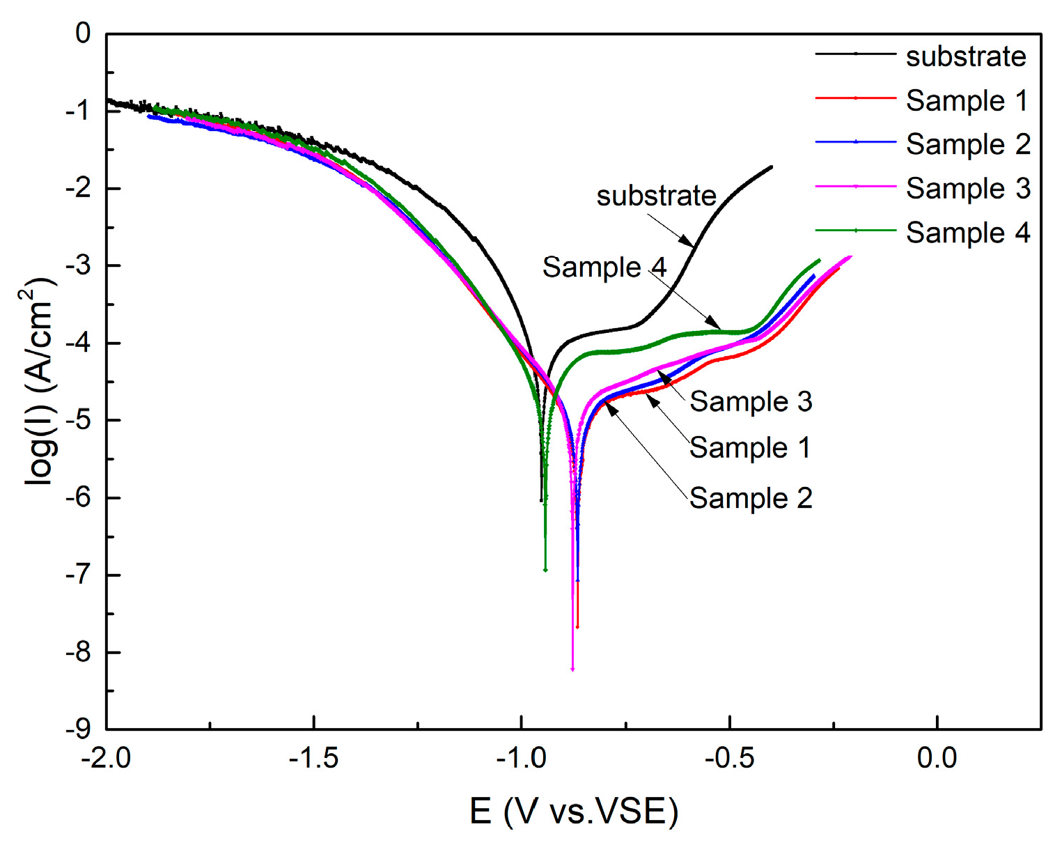
3.3.2. Polarization Curves

The polarization curves of the substrate and coating samples immersed in experimental solutions are shown in Figure 11. It clearly shows that the activated state shifted to a passivated state in the substrate and all samples. A stable passivation film formed on the surfaces of the substrate and coatings. The transition-passivated state of the substrate and Sample 4 are more clearly shown in Figure 11. It shifted from a passivated state to an over-passivated state quickly, and the passivation film located on the substrate surface dissolved. The coatings’ passivated curve interval increased similarly to that of the substrate. The passivation film was quickly formed on Sample 1–3, and the time it took for the film to dissolve was much longer in all samples compared to the substrate. The polarization curve shifted to the right, which indicates that the corrosion rate decreased. The corrosion potential of the substrate was the lowest, and that of Sample 1 was the highest in Figure 11. The curves show that the coatings had good corrosion resistance, and Sample 1 had the best corrosion resistance.
The electrochemical parameters related to polarization curves are shown in Table 4. OCP is open circuit potential, Ecorr is the corrosion potential, icorr is the corrosion current, and jcorr is the corrosion current density. The corrosion potential Ecorr of coatings increased compared to the substrate, and the corrosion current icorr decreased. The corrosion current of Sample 1 was the lowest, and the corrosion rate was the slowest, indicating that it had the best corrosion resistance. Sample 2 also had good corrosion resistance, which was superior to that of Sample 3. The corrosion of Sample 4 was the highest of all coating samples. The analysis is consistent with the EIS results.

4. Discussion

The microstructural XRD and EDS analyses showed that the M3B2-type boride-based cermet coating was successfully fabricated by laser cladding synthesis. The property tests show that the hardness and corrosion resistance greatly improved. The influences of the laser cladding process, including pretreatments and aftertreatments on the microstructure and phase composition of M3B2 cermet coatings and properties, were investigated. The diffraction peak intensity of the M3B2 phase was stronger in coatings using the squash presetting method than the PVB binder presetting method. The intensity of the M3B2 phase of Sample 1 increased after remelting treatment, whereas it decreased when Sample 3 was remelted. The intensity of the {Fe, Ni} phase of Sample 1 decreased after remelting, whereas it increased when Sample 3 was remelted. The same phenomenon was found in the microstructure analysis.
Polyvinyl butyral powder was dissolved in alcohol, then the saturated solution was mixed with raw powder after being milled. The pasty mass was brushed onto the substrate, but uniformity of the application could not be ensured. The lack of uniformity and poor fluidity caused a difference in the quantity of powder that could react. The non-uniform distribution of the M3B2 phase in the coating is shown in the SEM (Figure 3), which caused a three-layer arrangement to form in the coating. The powder was pressed onto the substrate after being milled, the thickness of the layer was even, and the spherical powder automatically filled the gaps under the press. The microstructure was distributed uniformly in the coating, but the three-layer arrangement was not clear in SEM. Because of the high density of the presetting layer, a thicker coating was formed by the squash presetting method. Partially unreacted elements would react after remelting, which caused the M3B2 phase intensity to increase, and a large amount of the M3B2 phase formed in Sample 2. The Fe element of the substrate would dissolve in the coating while all the elements reacted, which caused the {Fe, Ni} phase intensity and dilution rate to increase in Sample 4. The powders melted rapidly after laser scanning, and the powders reacted and released lots of heat; a molten pool was formed by the heat of the reaction and the laser. Parts of the substrate were melted, generating large amounts of heat; the molten pool cooled rapidly after laser scanning, and the bottom layer consisted of the gray phase, formed because of substrate dilution. The thickness of the coating using the squash presetting method resulted in less and less energy being conducted to the substrate, and the bottom layer was thinner, which meant low dilution of the coating.
A harder coating was obtained by the squash presetting method, according to hardness analysis. A large amount of the M3B2 phase formed uniformly in Sample 3, according to XRD and microstructure analyses. Reacting M3B2 with elements accelerated the nucleation, and the hardness increased under dispersion strengthening. On one hand, remelting will reduce the defects of coating, such as holes and cracks, promoting the reaction; on the other hand, remelting will increase the dilution rate for the substrate element dissolved in the coating. This is why the hardness of Sample 2 increased and the hardness of Sample 4 decreased.
The coating resulted in a good protective substrate under all process parameters. The corrosion current of cermet coating using the PVB binder presetting method was 6.35 μA, and it was 10.05 μA when the squash presetting method was used. The diameter of the capacitive reactance arc of Sample 1 was larger, and the polarization resistance Rp was also larger in the fitting results (Rp Sample 1 = 2534 Ω·cm2, Rp Sample 3 = 1551 Ω·cm2). All these showed that the corrosion resistance of the coating using the PVB binder method was better. The corrosion current increased, and arc diameter and polarization resistance decreased, when the samples were remelted. The boride cermet phase was surrounded by a metal phase in the coating; the cermet is a cathode, whereas the metal phase is an anode in the corrosion system. Because massive corrosion cells formed, the M3B2 phase promoted the corrosion of metal matrix anodes. Thus, the presence of a large amount of M3B2 phase in the top layer of Sample 3 could accelerate the surface corrosion and worsen the corrosion resistance of the coatings formed using the squash presetting method. In addition, a large amount of the cermet phase formed in Sample 2 after remelting, and the cermet phase diffused to the top layer of the coating, which led to an inferior corrosion resistance of Sample 2 compared to Sample 1. In a similar way, the elements in the substrate dissolved to the top coating in Sample 4, and consequently, the metal matrix corroded in an accelerated manner.
Formation of a passivation film on the surface of cermet coatings could improve the corrosion resistance of the coatings [31]. In the corrosion cells, anodic dissolution of the metal and the cathodic consumption of the soluble O2 could favor formation of the passivation film. The procedure of the electrochemical reaction and the formation of passivation films during the experiments are as follows:
Anodic reaction:
M = M n + + n e
Cathodic reaction:
n 2 H 2 O + n 4 O 2 + n e = n OH
The corrosion reaction is as follows:
M n + + n OH = M ( OH ) n
where M is the metal elements in a layer (according to the XRD and SEM analyses, M is Fe and Ni), and n+ is the valence of elements. Formation of the passivation film can reduce the surface portion of the anodic dissolution process, consequently reducing the average velocity of the anodic dissolution process and improving the corrosion resistance of the cermet coatings. Passive films formed anodically on carbon steel have been characterized by electrochemical impedance spectroscopy in the work of Hamadou et al. [32]. This indicates that a stable passive state formed, and the number of defects decreased with increasing film thickness. The corrosion behavior of austenitic stainless steels was investigated in NaCl solution at room temperature by Toor [33]. This and similar studies showed that stabilizing the passive film increased the corrosion resistance.
The three-layer-type coating has good properties, and it has an especially dense M3B2 phase in the middle layer and a smaller amount of M3B2 phase in the top layer. The combination property of the substrate can be greatly improved, whereas the coating is fabricated on the substrate in the three-layer-type above. The control of the rate of formation of M3B2 in coating using the squash presetting method and the improvement of the uniformity using the PVB binder presetting method will be investigated in the future. Friction and wear properties will also be researched.

5. Conclusions

M3B2 boride complex coatings were developed by laser cladding synthesis. Four processing parameters were used in the experiments, which influenced the microstructure and properties of the coatings. X-ray diffraction, SEM, and EDS analyses showed a white M3B2 phase and a light-gray {Fe, Ni} phase distributed in the coating. The thickness of the coatings increased after remelting. A thicker coating could be made when the squash presetting method was used. The structure in the coating using the PVB binder presetting method had more obvious stratification than the structure formed using the squash presetting method. The microstructure in the coating using the squash presetting method was highly uniform and fine. The hardness increased, and the maximum value achieved in the middle layer of the coating then decreased from the surface of the coating to the substrate in all samples. The average hardness was higher using the squash presetting method, and remelting technology had a big effect on the hardness. The corrosion resistance of all coatings improved compared to the substrate.
The complex coatings possess good properties, and they can be used for remanufacturing key aspects of moving parts and in additive manufacturing of small complex structure parts applied in marine environments. This new, laser-induced method helps to synthesize a ternary boride complex coating directly on the substrate.

Author Contributions

Data curation, Z.H.; Formal analysis, Z.H.; Investigation, Z.H.; Writing–original draft preparation, Z.H.; Funding acquisition, W.L.; Project administration, W.L.; Supervision, W.L.; Methodology, Y.Z.; Writing–review & editing, Y.Z.

Funding

This research was funded by National Natural Science Foundation of China, grant number 51572168.

Acknowledgments

The authors acknowledge Shanghai Lin Shi Laser Technology Co., Ltd., for experiment support. Professor Chunwang Liu from Shanghai Maritime University is acknowledged for help.

Conflicts of Interest

The authors declare no conflict of interest regarding the publication of this article.

References

  1. Liu, F.G.; Du, M.; Zhang, J.; Qiu, M. Electrochemical behavior of Q235 steel in saltwater saturated with carbon dioxide based on new imidazoline derivative inhibitor. Corros. Sci. 2009, 51, 102–109. [Google Scholar] [CrossRef]
  2. Han, E.; Chen, J.; Su, Y.; Liu, M. Corrosion protection techniques of marine engineering structure and ship equipment- current status and future trend. Mater. Chin. 2014, 33, 65–76. [Google Scholar] [CrossRef]
  3. Wang, H.Q.; Sun, J.S.; Li, C.N.; Geng, S.N.; Sun, H.G.; Wang, G.L. Microstructure and mechanical properties of molybdenum–iron–boron–chromium cladding using argon arc welding. Mater. Sci. Technol. 2016, 32, 1694–1701. [Google Scholar] [CrossRef]
  4. Zhang, T.; Yin, H.; Zhang, C.; Zhang, R.; Xue, J.; Zheng, Q.; Qu, X. First-principles study on the mechanical properties and electronic structure of V doped WCoB and W2CoB2 ternary borides. Materials 2019, 12, 967. [Google Scholar] [CrossRef] [PubMed]
  5. Li, Q.; Zhou, D.; Zheng, W.; Ma, Y.; Chen, C. Global structural optimization of tungsten borides. Phys. Rev. Lett. 2013, 110, 136403. [Google Scholar] [CrossRef]
  6. Bahrami-Karkevandi, M.; Ebrahimi-Kahrizsangi, R.; Nasiri-Tabrizi, B. Formation and stability of tungsten boride nanocomposites in WO3–B2O3–Mg ternary system: Mechanochemical effects. Int. J. Refract. Met. Hard Mater 2014, 46, 117–124. [Google Scholar] [CrossRef]
  7. Kadri, M.T.; Heciri, D.; Derradji, N.; Belfarhi, B.; Belkhir, H. Effects of Na, Mg and Al substitution in hypothetical superconducting Be2B. Phys. Status Solidi B 2008, 245, 2779–2785. [Google Scholar] [CrossRef]
  8. Togano, K.; Badica, P.; Nakamori, Y.; Orimo, S.; Takeya, H.; Hirata, K. Superconductivity in metal rich Li-Pd-B ternary boride. Phys. Rev. Lett. 2004, 93, 247004. [Google Scholar] [CrossRef]
  9. Prakash, S.; Karacor, M.; Banerjee, S. Surface modification in microsystems and nanosystems. Surf. Sci. Rep. 2009, 64, 233–254. [Google Scholar] [CrossRef]
  10. Kayhan, M.; Hildebrandt, E.; Frotscher, M.; Senyshyn, A.; Hofmann, K.; Alff, L.; Albert, B. Neutron diffraction and observation of superconductivity for tungsten borides, WB and W2B4. Solid State Sci. 2012, 14, 1656–1659. [Google Scholar] [CrossRef]
  11. Moraes, V.; Riedl, H.; Fuger, C.; Polcik, P.; Bolvardi, H.; Holec, D.; Mayrhofer, P. Ab initio inspired design of ternary boride thin films. Sci. Rep. 2018, 8, 1–9. [Google Scholar] [CrossRef]
  12. Takagi, K.-I. Development and application of high strength ternary boride base cermets. J. Solid State Chem. 2006, 179, 2809–2818. [Google Scholar] [CrossRef]
  13. Yuan, B.; Zhang, G.-J.; Kan, Y.-M.; Wang, P.-L. Reactive synthesis and mechanical properties of Mo2NiB2 based hard alloy. Int. J. Refract. Met. Hard Mater. 2010, 28, 291–296. [Google Scholar] [CrossRef]
  14. Takagi, K.-I.; Koike, W.; Momozawa, A.; Fujima, T. Effects of Cr on the properties of Mo2NiB2 ternary boride. Solid State Sci. 2012, 12, 1643–1647. [Google Scholar] [CrossRef]
  15. Yu, H.; Zheng, Y.; Liu, W.; Zheng, J.; Xiong, W. Effect of V content on the microstructure and mechanical properties of Mo2FeB2 based cermets. Mater. Des. 2010, 31, 2680–2683. [Google Scholar] [CrossRef]
  16. Haizhou, Y.; Wenjun, L.; Ping, F.; Yong, Z. Synthesis and microstructure evolution during vacuum sintering of Mo2FeB2 based cermets. Int. J. Refract. Met. Hard Mater. 2014, 45, 48–52. [Google Scholar] [CrossRef]
  17. Magnani, M.; Suegama, P.; Espallargas, N.; Fugivara, C.S.; Dosta, S.; Guilemany, J.; Benedetti, A.V. Corrosion and wear studies of Cr3C2NiCr-HVOF coatings sprayed on AA7050 T7 under cooling. J. Therm. Spray Technol. 2009, 18, 353–363. [Google Scholar] [CrossRef]
  18. Keränen, J.; Stenberg, T.; Mäntylä, T.; Lepistö, T. Micro structural characterization of detonation gun-sprayed boride-based cermet coatings. Surf. Coat Technol. 1996, 82, 29–37. [Google Scholar] [CrossRef]
  19. Wei, X.; Chen, Z.; Zhong, J.; Xiang, Y. Feasibility of preparing Mo2FeB2- based cermet coating by electrospark deposition on high speed steel. Surf. Coat. Technol. 2016, 296, 58–64. [Google Scholar] [CrossRef]
  20. Zhou, X.P.; Hu, X.B.; Xu, Y.S. The microstructure and properties of coating from Mo2FeB2 cermet on surface of H13 steel by reactive flame spraying. Adv. Mater. Res. 2010, 97–101, 1321–1327. [Google Scholar] [CrossRef]
  21. Zhuang, M.; Wei, W.; Zou, J.-F.; Dong, S.-Z.; Zhang, L.-Y.; Li, Z.-C. Preparation and properties of flame-sprayed Mo-FeB-Fe cermet coatings. Trans. Nonferrous Met. Soc. Chin. 2011, 21, 1314–1321. [Google Scholar] [CrossRef]
  22. Vencl, A.; Mrdak, M.; Banjac, M. Correlation of microstructures and tribological properties of ferrous coatings deposited by atmospheric plasma spraying on Al–Si cast alloy substrate. Metall. Mater. Trans. A 2009, 40, 398–405. [Google Scholar] [CrossRef]
  23. Manna, I.; Majumdar, J.D.; Chandra, B.R.; Nayak, S.; Dahotre, N.B. Laser surface cladding of Fe–B–C, Fe–B–Si and Fe–BC–Si–Al–C on plain carbon steel. Surf. Coat. Technol. 2006, 201, 434–440. [Google Scholar] [CrossRef]
  24. Sexton, L.; Lavin, S.; Byrne, G.; Kennedy, A. Laser cladding of aerospace materials. J. Mater. Process. Technol. 2002, 122, 63–68. [Google Scholar] [CrossRef]
  25. Agarwal, A.; Dahotre, N.B. Laser surface engineering of steel for hard refractory ceramic composite coating. Int. J. Refract. Met. Hard Mater 1999, 17, 283–293. [Google Scholar] [CrossRef]
  26. Wu, Q.; Li, W.; Zhong, N.; Wang, G. Microstructure and properties laser-clad Mo2NiB2 cermet coating on steel substrate. Steel Res. Int. 2014, 85, 1–9. [Google Scholar] [CrossRef]
  27. Wang, Y.; Cheng, G.; Wu, W.; Qiao, Q.; Li, Y.; Li, X. Effect of pH and chloride on the micro-mechanism of pitting corrosion for high strength pipeline steel in aerated NaCl solutions. Appl. Surf. Sci. 2015, 349, 746–756. [Google Scholar] [CrossRef]
  28. Quej-Aké, L.; Contreras, A.; Aburto, J. Electrochemical study on corrosion inhibition of X52 steel by non-ionic surfactant in substitute ocean water. Int. J. Electrochem. Sci. 2018, 12, 7416–7431. [Google Scholar] [CrossRef]
  29. Xie, F.; Guo, Z.; Wang, D.; Li, R.; Wu, M.; Zong, Y.; Wang, Y. Synergistic effect between chloride and sulfate reducing bacteria in corrosion inhibition of X100 pipeline steel in marine environment. Int. J. Electrochem. Sci. 2019, 14, 2693–2704. [Google Scholar] [CrossRef]
  30. Brytan, Z.; Niagaj, J. Corrosion studies using potentiodynamic and EIS electrochemical techniques of welded lean duplex stainless steel UNS S82441. Appl. Surf. Sci. 2016, 388, 160–168. [Google Scholar] [CrossRef]
  31. Barsoukov, E.; Macdonald, J.R. Impedance Spectroscopy: Theory, Experiment, and Applications; John Wiley & Sons: Hoboken, NJ, USA, 2018; pp. 365–381. ISBN 0-471-64749-7. [Google Scholar]
  32. Hamadou, L.; Kadri, A.; Benbrahim, N. Characterisation of passive films formed on low carbon steel in borate buffer solution(pH 9.2) by electrochemical impedance spectroscopy. Appl. Surf. Sci. 2005, 252, 1510–1519. [Google Scholar] [CrossRef]
  33. Toor, I.-U.-H. Effect of Mn content and solution annealing temperature on the corrosion resistance of stainless steel alloys. J. Chem. 2014, 388, 1–18. [Google Scholar] [CrossRef]
Figure 1. Preparation flow chart of M3B2-based cermet coatings on Q235 steels.
Coatings 09 00476 g001
Figure 2. X-ray diffraction patterns of coatings: (a) Sample 1; (b) Sample 2; (c) Sample 3; and (d) Sample 4.
Coatings 09 00476 g002
Figure 3. The microstructure scanning electron microscopy (SEM) images of coatings: (a) Sample 1; (b) Sample 2; (c) Sample 3; and (d) Sample 4.
Coatings 09 00476 g003
Figure 4. Energy-dispersive X-ray spectroscopy (EDS) line scan of the cross-section of coatings: above is the scan position, below is the distribution of elements.
Coatings 09 00476 g004
Figure 5. Elemental map of coating by EDS: (a) SEM morphology; (b) Mo; (c) Ni; (d) Fe; (e) Cr; (f) B; and (g) W.
Coatings 09 00476 g005aCoatings 09 00476 g005b
Figure 6. Positions of hardness test points.
Coatings 09 00476 g006
Figure 7. Vickers hardness of boride-based composite coatings.
Coatings 09 00476 g007
Figure 8. Nyquist diagrams for substrate and coatings immersed in 3.5% NaCl solution.
Coatings 09 00476 g008
Figure 9. Bode diagrams for substrate and coatings immersed in 3.5% NaCl solution.
Coatings 09 00476 g009
Figure 10. Equivalent circuit model of samples immersed in 3.5% NaCl solution.
Coatings 09 00476 g010
Figure 11. Polarization curves of substrate and coating samples immersed in 3.5% NaCl solution.
Coatings 09 00476 g011
Table 1. Composition of powder.
ElementMoNiBCrFeSiWC
wt %61.7218.886.955.064.871.30.970.26
Table 2. Laser cladding parameters.
Sample No.Presetting MethodLaser Power (W)Scanning Speed (mm/s)Lapping Rate (%)Remelting Power (W)Remelting Speed (mm/s)
1Polyvinyl butyral (PVB) binder800330NONO
2PVB binder80033010004
3Squash800330NONO
4Squash80033010004
Table 3. Fitted values of the equivalent circuit of the electrochemical impedance spectra (EIS) diagram.
Sample No.Rs (Ω·cm2)Rf (Ω·cm2)Qf, Y0
(m·Ω−1·cm−2·sn)
Rct (Ω·cm2)Qdl, Y0
(m·Ω−1·cm−2·sn)
Substrate3.636.251.549801.72
14.861740.3124600.34
24.517100.9614201.61
33.424510.4111000.94
41.172.321.1613600.77
Table 4. Electrochemical parameters obtained from polarization curves of samples.
Sample No.Open Circuit Potential (OCP) (V)Ecorr (V)icorr (μA)jcorr (μA/cm2)
Substrate−0.59−0.9543.7643.76
1−0.52 −0.886.356.35
2−0.55 −0.878.308.30
3−0.50 −0.8910.0510.05
4−0.53 −0.9514.4214.42

