
Multi-Scale Toughening of UHPC: Synergistic Effects of Carbon Microfibers and Nanotubes


Abstract
Highlights
- Ultra-High Performance Concrete (UHPC) was reinforced at multiple scales using carbon microfibers and carbon nanotubes without compromising workability.
- This hybrid reinforcement increased compressive strength by 39%, tensile strength by 313%, and reduced macroporosity by 42%.
- The multi-scale reinforcement improves UHPC durability and fracture resistance.
- The carbon-based reinforcement offers a corrosion-free alternative for offshore and marine structures.
Abstract
1. Introduction
2. Materials and Methods
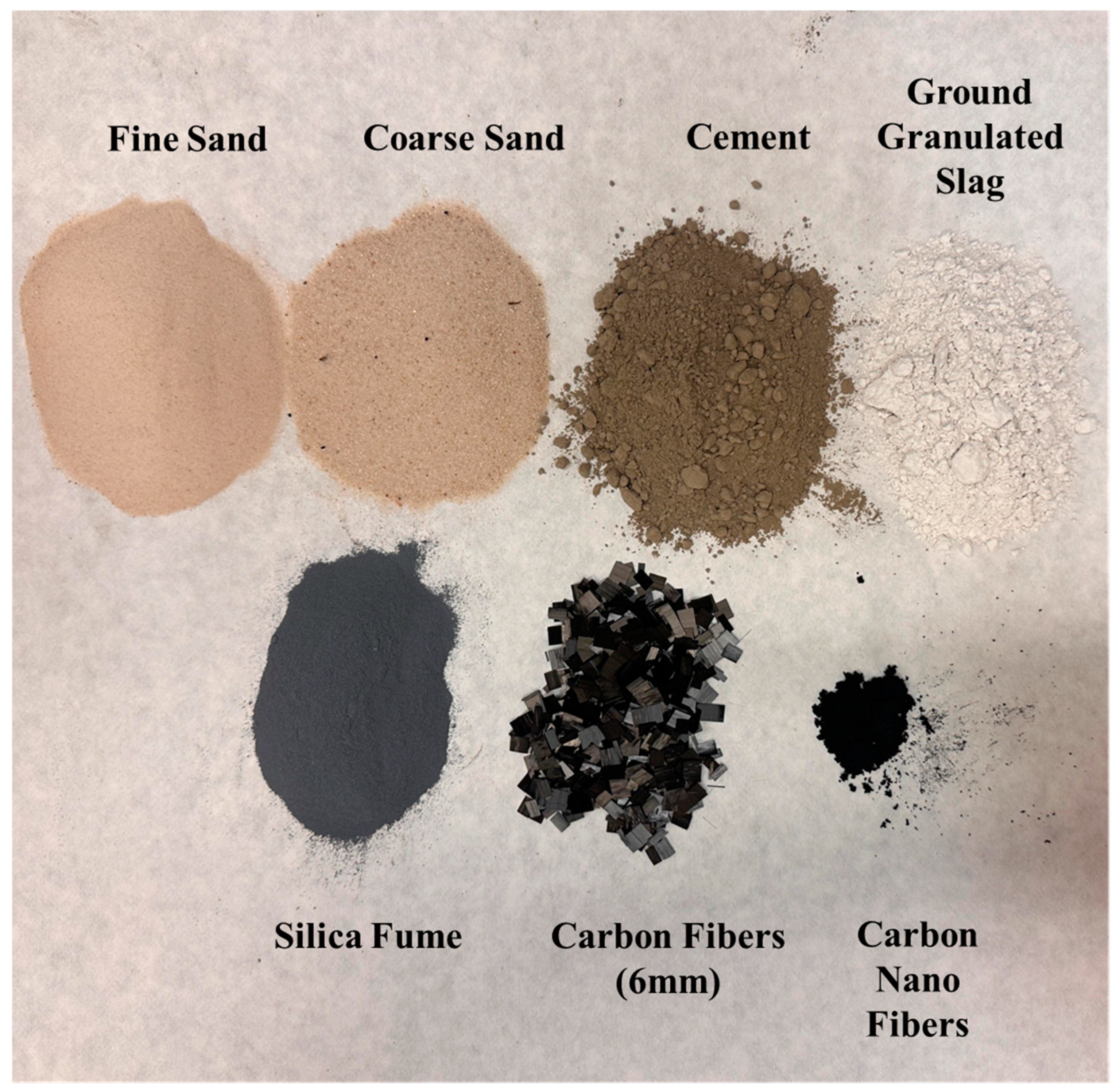
2.1. Materials
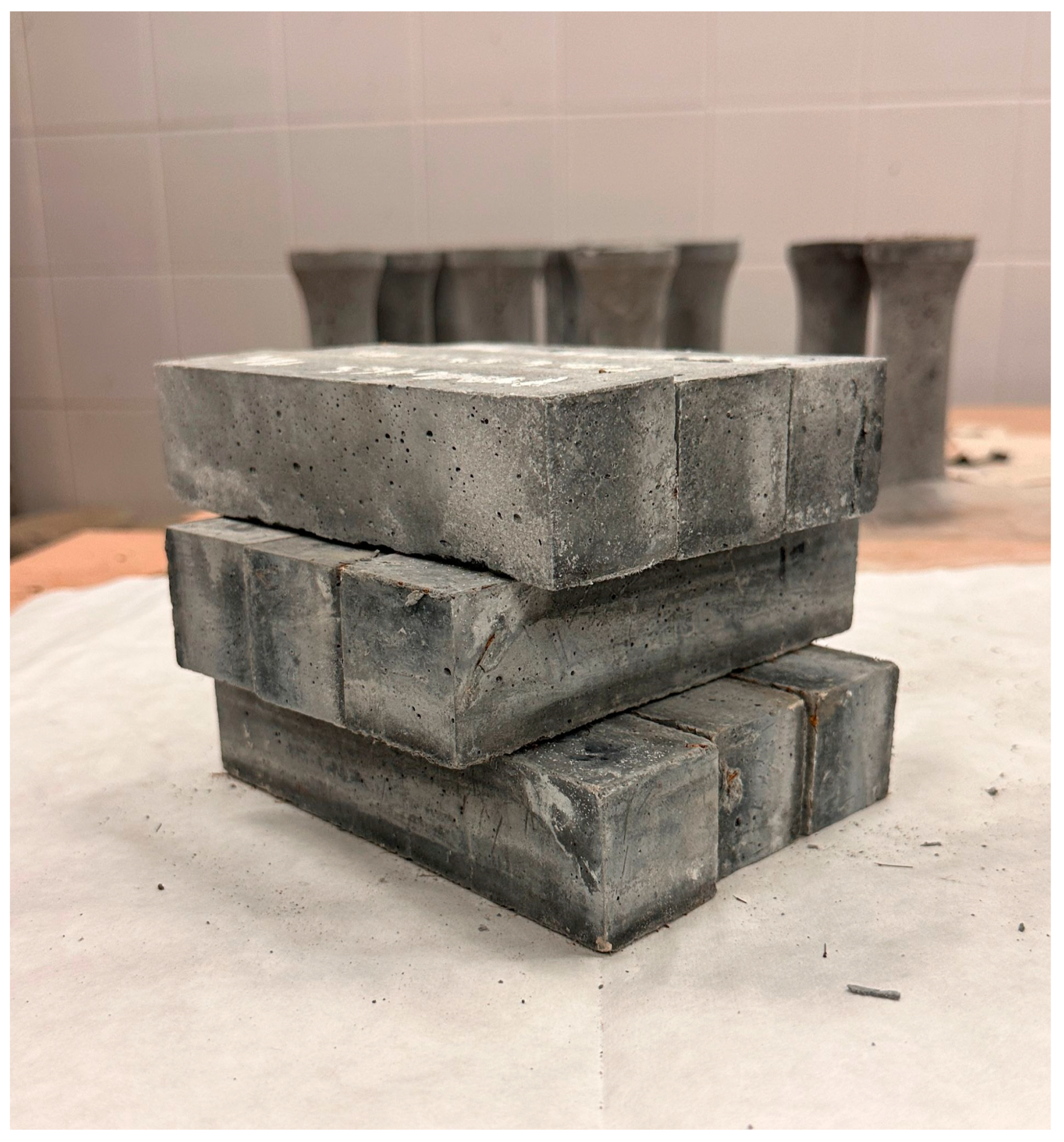
2.2. Mix Proportions and Specimen Preparation
2.3. Experimental Program
2.3.1. Workability
2.3.2. Pore Size Distribution Through X-Ray Computed Scan and Mercury Porosimetry
2.3.3. Thermogravimetric Analysis (TGA)
2.3.4. Scanning Electron Microscopy (SEM)
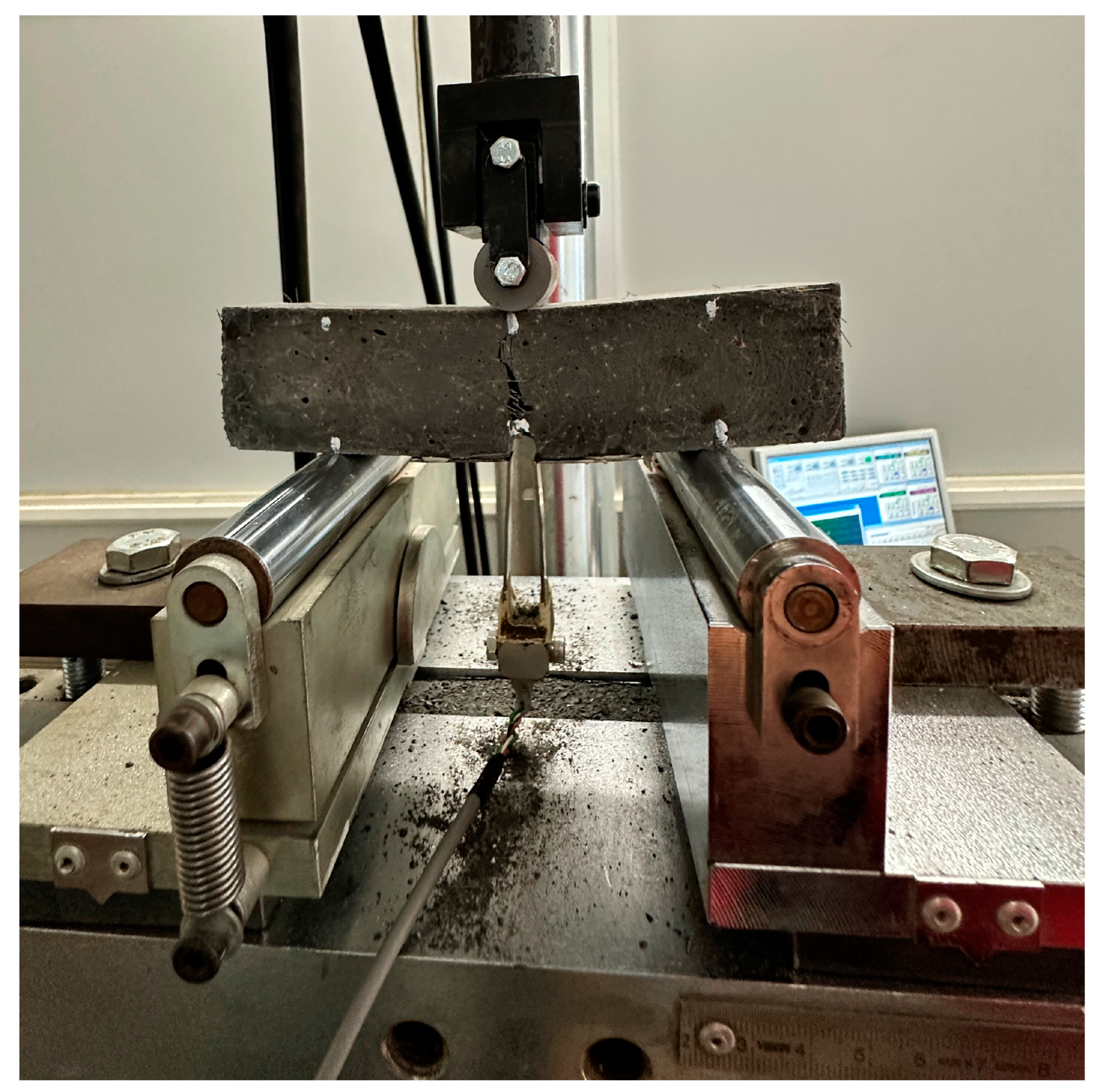
2.3.5. Mechanical Properties
Compressive Strength
Tensile Strength
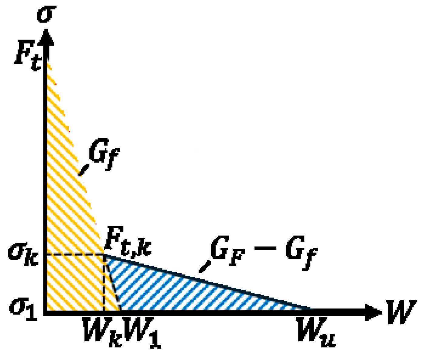
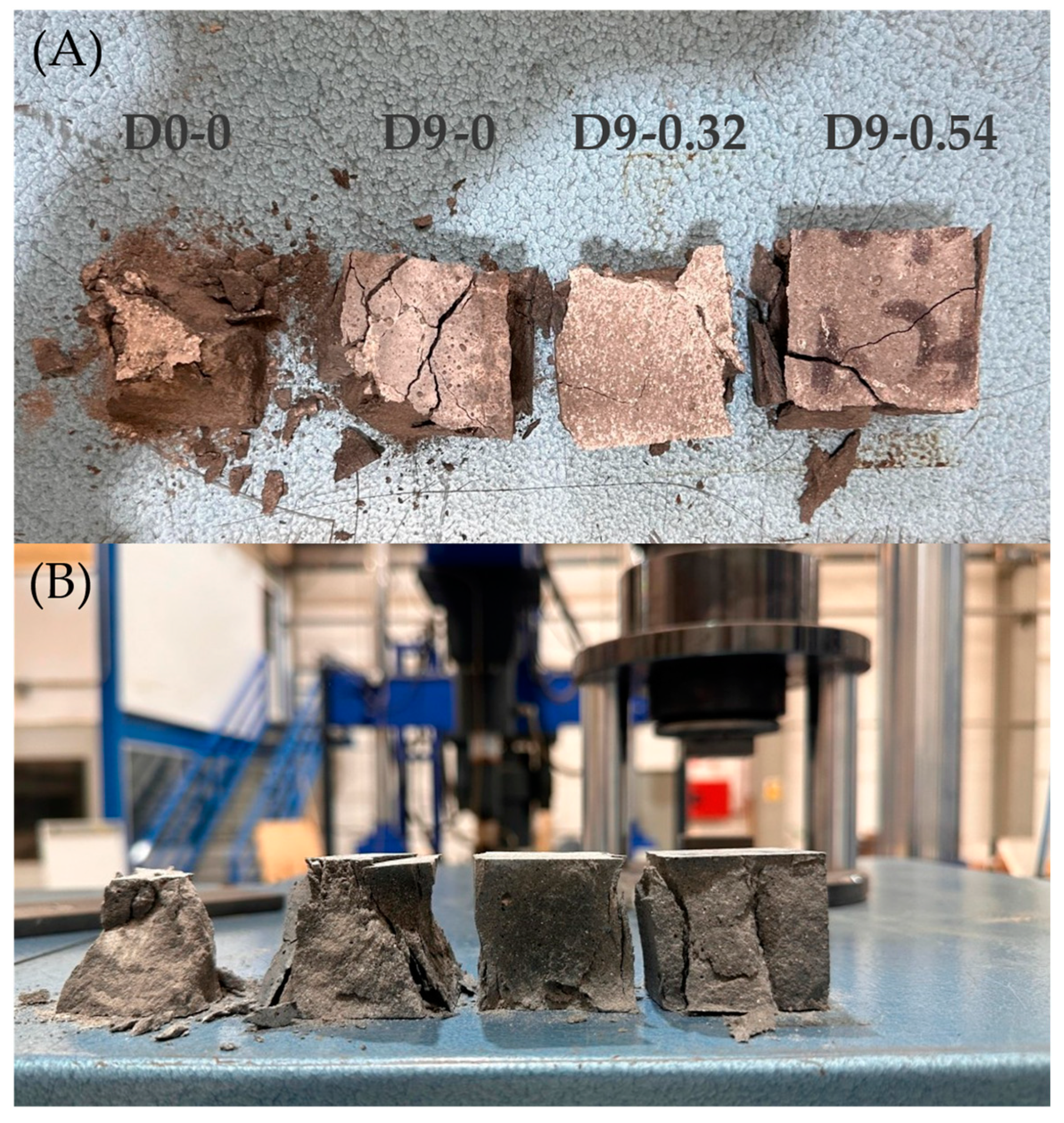
Fracture Behavior
3. Results and Discussion
3.1. Thermogravimetric Analysis
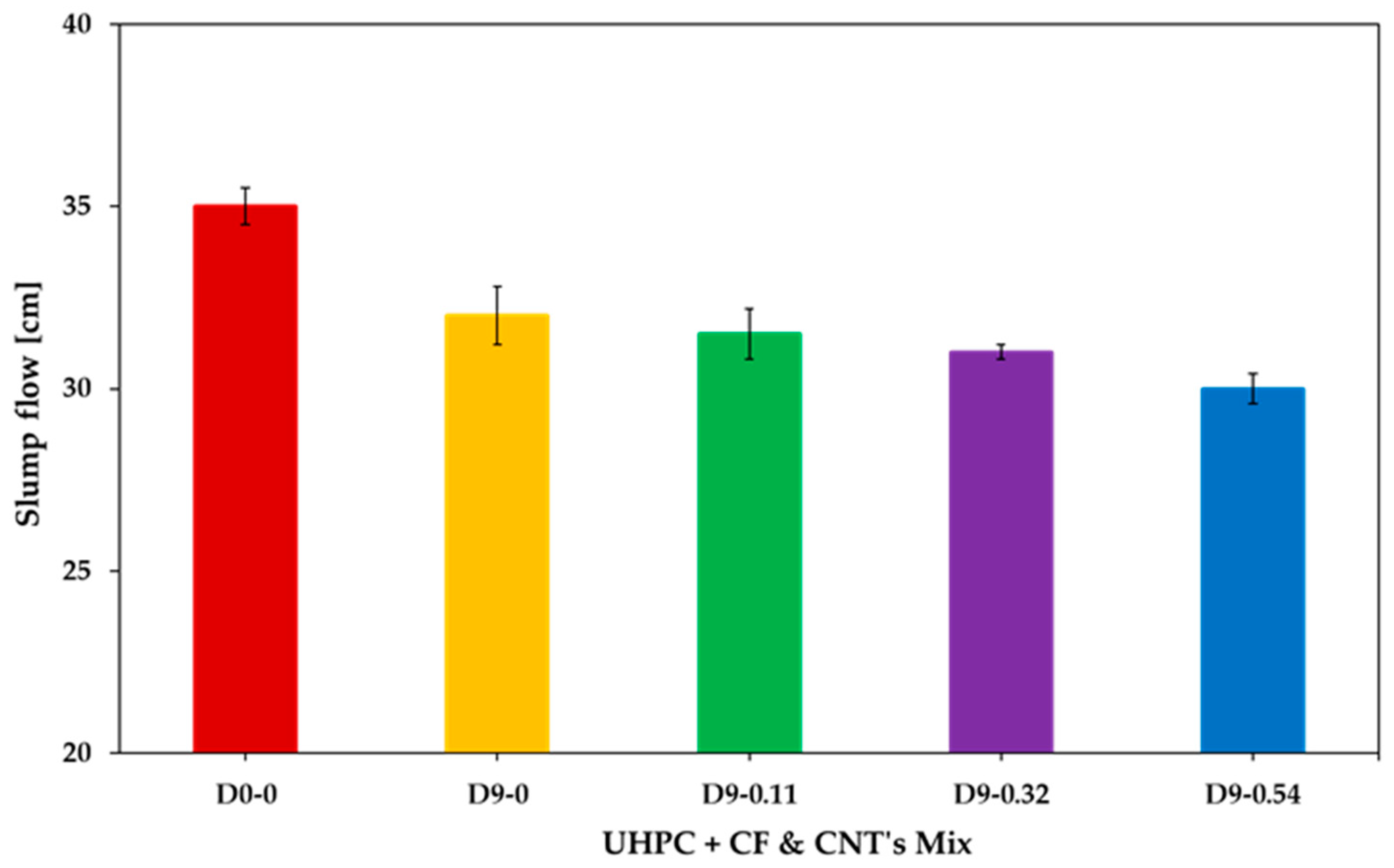
3.2. Workability
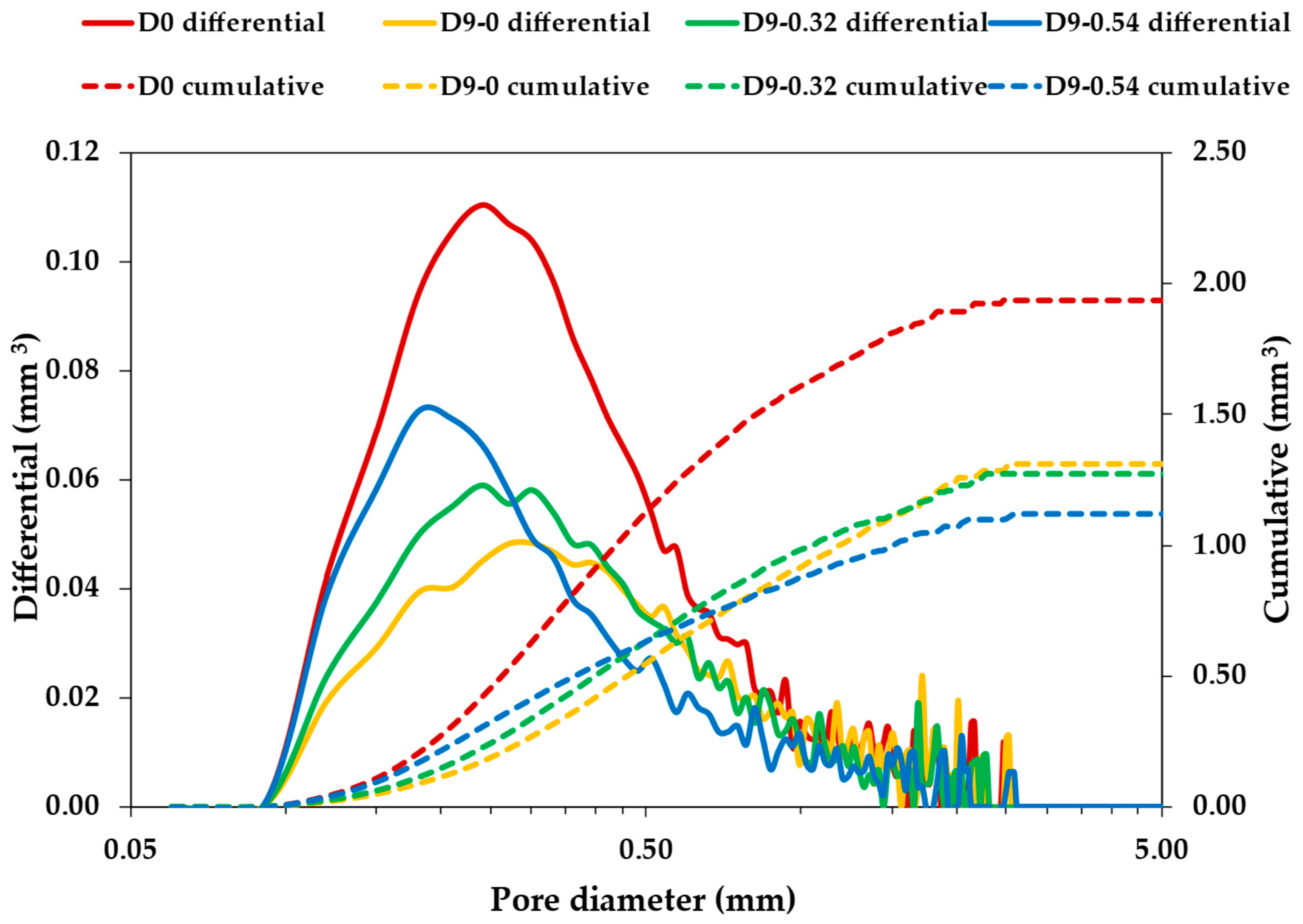
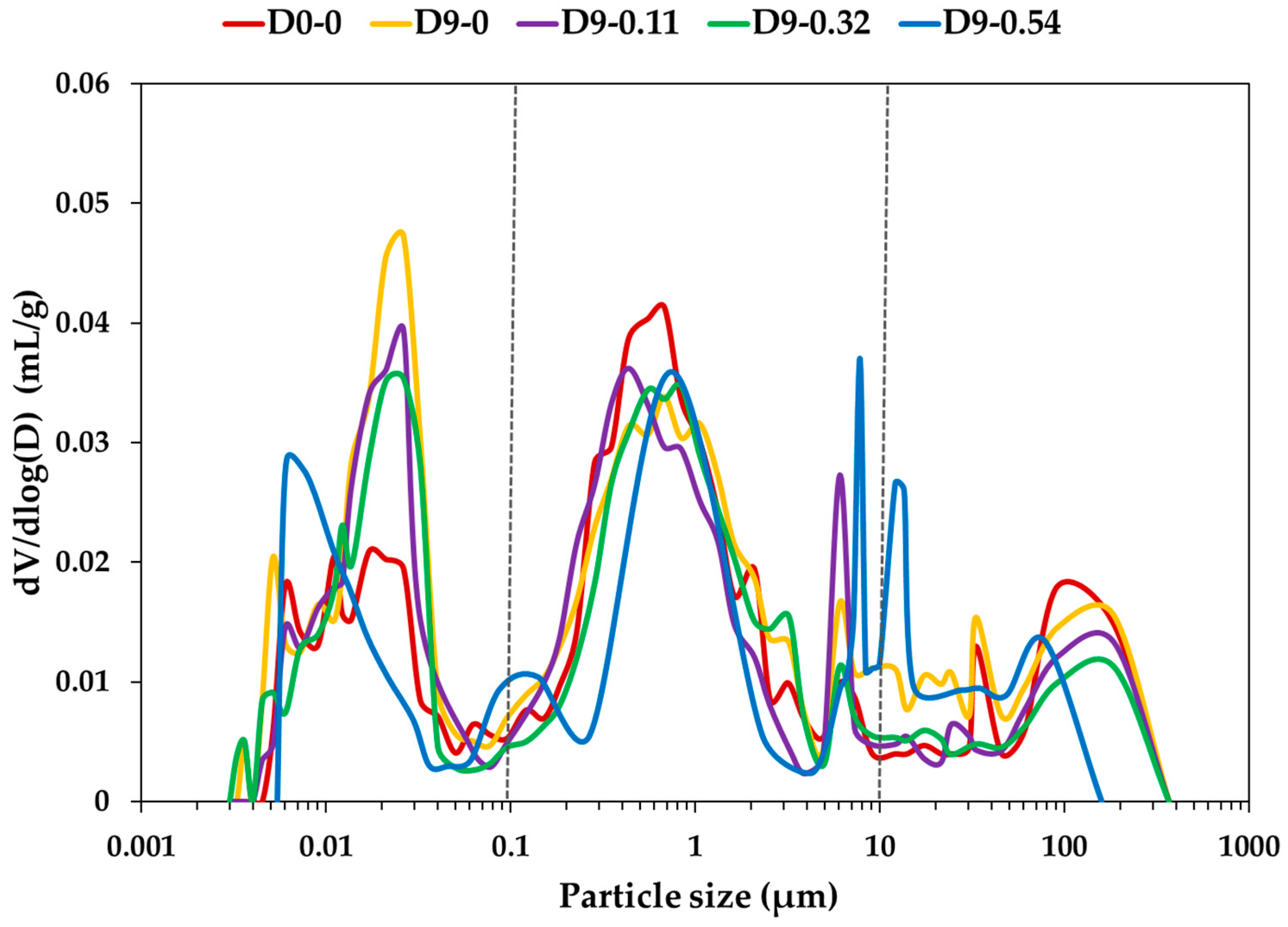
3.3. Pore Size Distribution Through X-Ray Computed Scan and Mercury Intrusion Porosimetry (MIP)
3.4. Mechanical Properties
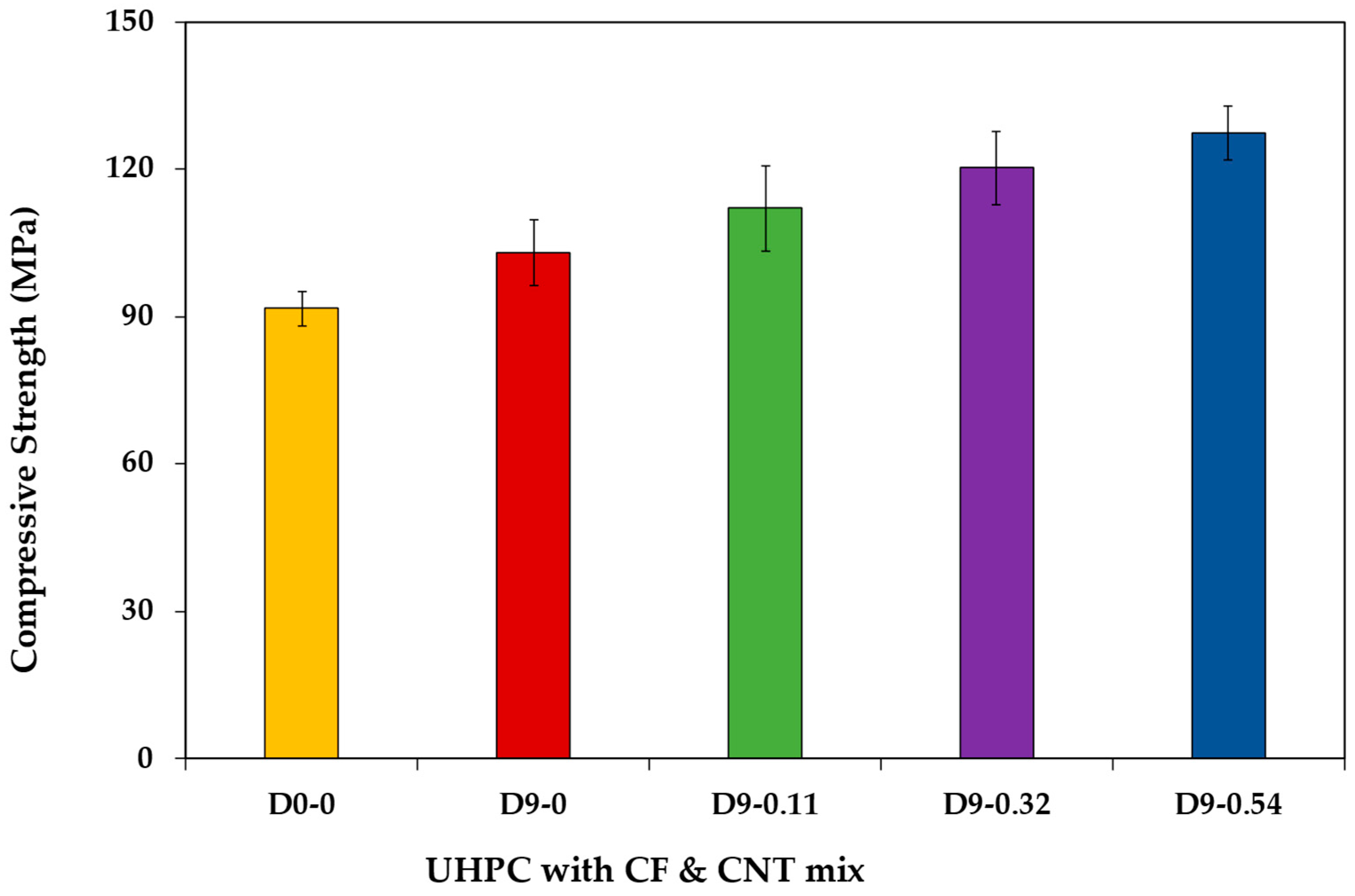
3.4.1. Compressive Strength
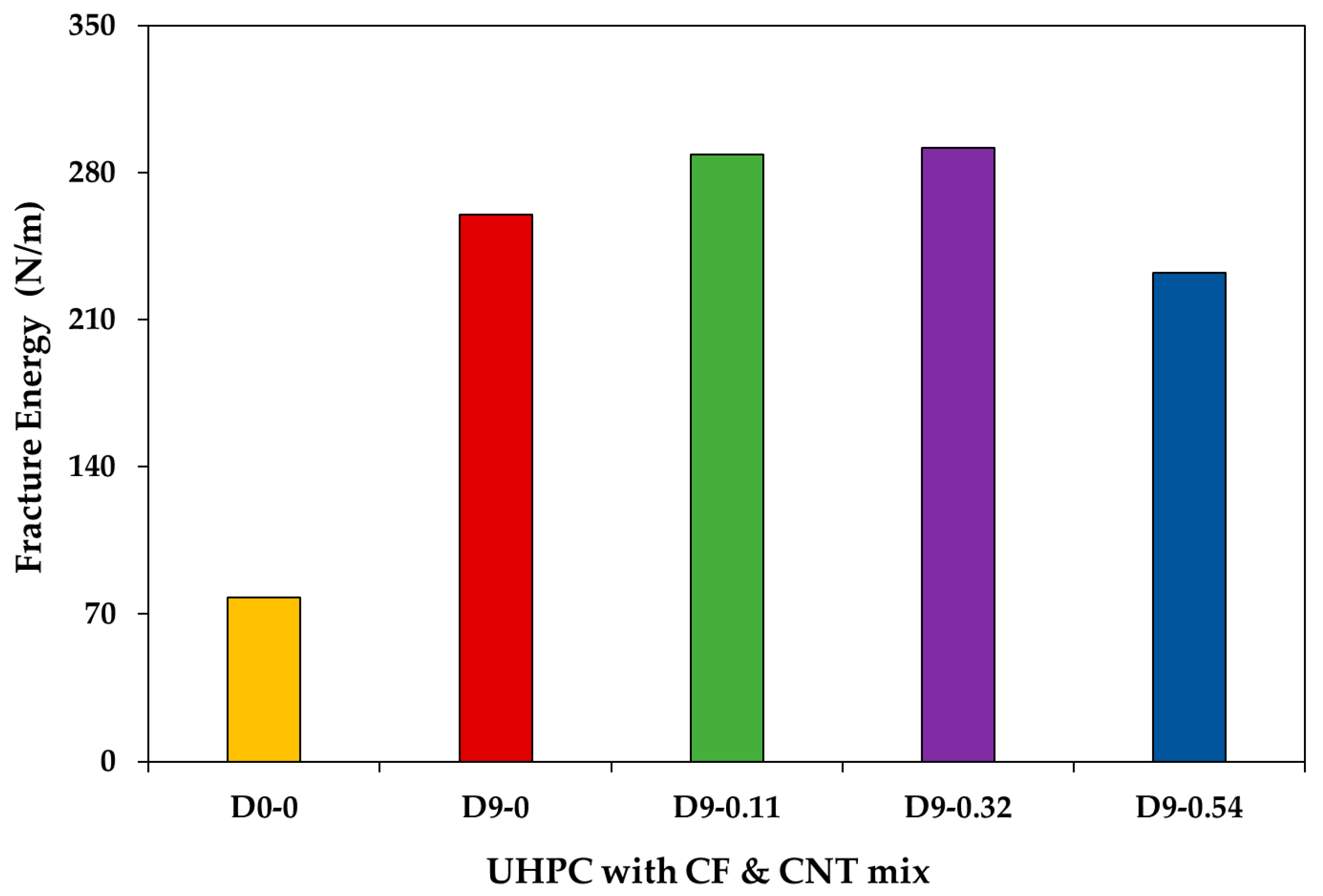
3.4.2. Fracture Behavior
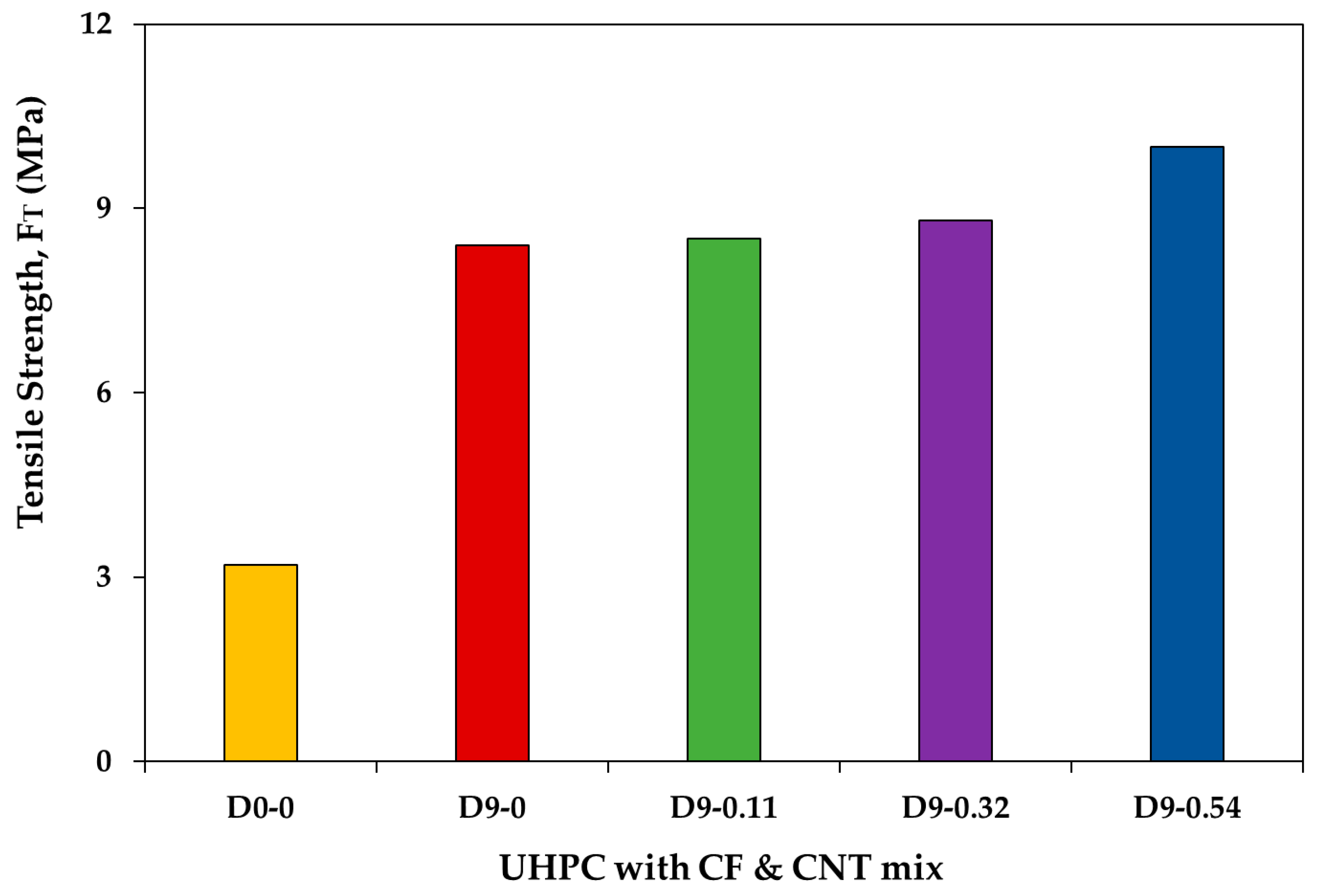
3.4.3. Tensile Strength
4. Discussion
5. Conclusions
- The non-corrosive nature CFs and of CNTs make UHPC a viable and durable material for infrastructure applications, particularly in harsh marine environments, where long-term performance is critical.
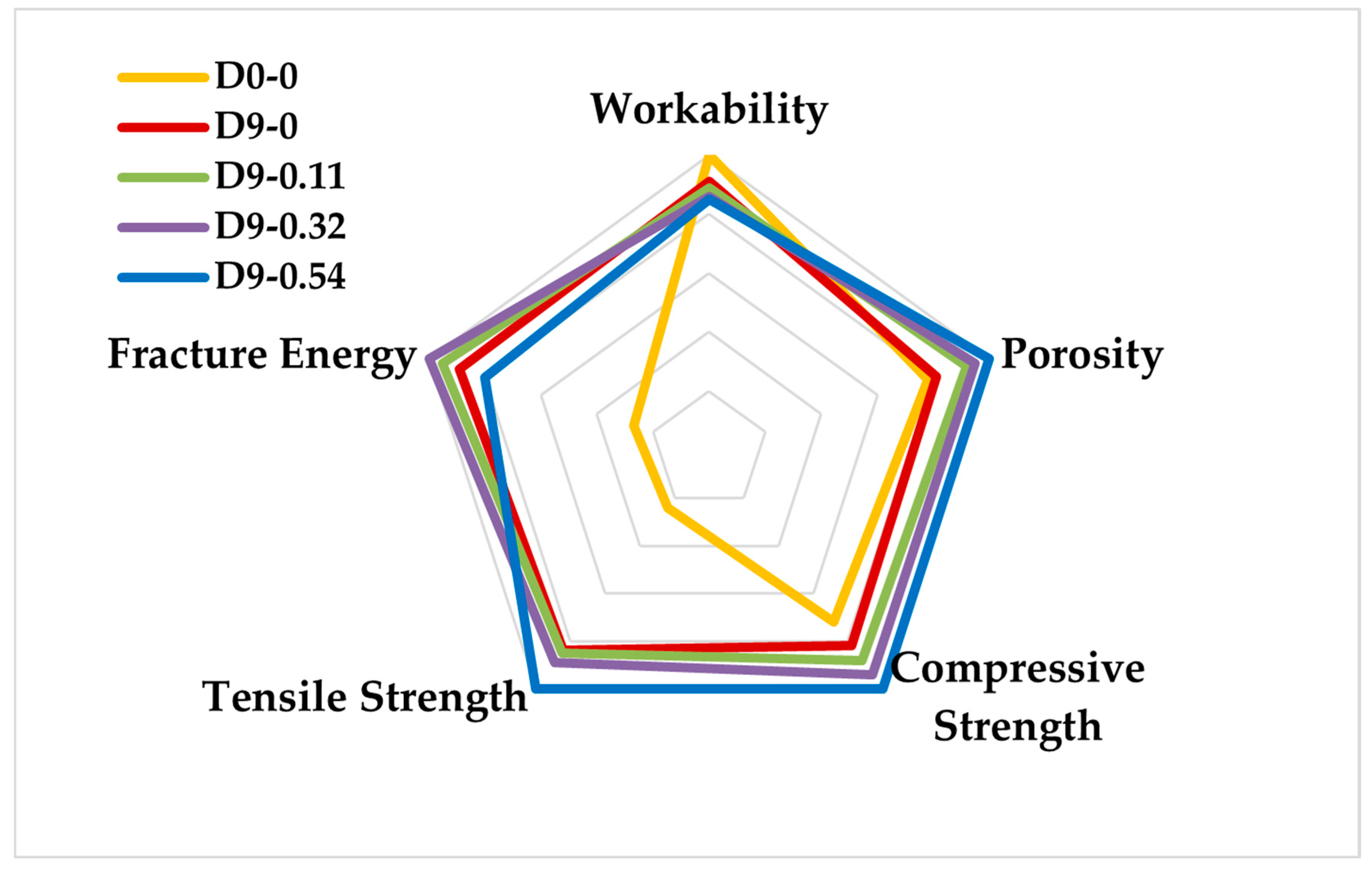
- CFs alone achieved a 32% reduction in macro-porosity, while higher concentrations of CNTs (0.54 kg/m3) further decreased macro-porosity by up to 42%. This resulted in a denser concrete matrix, potentially reducing brittleness and inhibiting crack initiation during fracture. Critically, the CNTs played a key role in refining the UHPC microstructure by filling nanoscale pores, decreasing porosity, and enhancing matrix density, which contributes to improved durability and resistance to internal defects.
- The thermal analysis revealed that CNTs slightly delayed the initial mass loss related to moisture and C–S–H dehydration, attributed to their strengthening of hydration products and formation of denser C–S–H agglomerates. CNTs also increased the mass loss from calcium hydroxide decomposition, indicating their ability to enhance pozzolanic reactions and C–S–H formation.
- CFs play a critical role in crack initiation and propagation. They create a bridging effect that modifies porosity and pore size distribution, enhancing energy absorption during fracture. CNTs also strengthen the bond between aggregates and the cement matrix.
- The synergistic integration of CFs and CNTs significantly enhanced UHPC’s mechanical performance—compressive strength increased up to 39% and tensile strength up to 313% at the highest dosage. Fracture energy also improved with optimized CF (9 kg/m3) and CNT (0.32 kg/m3) combinations.
Author Contributions
Funding
Data Availability Statement
Acknowledgments
Conflicts of Interest
References
- Huang, H.; Teng, L.; Khayat, K.H.; Gao, X.; Wang, F.; Liu, Z. For the Improvement of Mechanical and Microstructural Properties of UHPC with Fiber Alignment Using Carbon Nanotube and Graphite Nanoplatelet. Cem. Concr. Compos. 2022, 129, 104462. [Google Scholar] [CrossRef]
- Bajaber, M.A.; Hakeem, I.Y. UHPC Evolution, Development, and Utilization in Construction: A Review. J. Mater. Res. Technol. 2021, 10, 1058–1074. [Google Scholar] [CrossRef]
- Wang, Y.; Qiao, P.; Sun, J.; Chen, A. Influence of Fibers on Tensile Behavior of Ultra-High Performance Concrete: A Review. Constr. Build. Mater. 2024, 430, 136432. [Google Scholar] [CrossRef]
- Akhnoukh, A.K.; Buckhalter, C. Ultra-High-Performance Concrete: Constituents, Mechanical Properties, Applications and Current Challenges. Case Stud. Constr. Mater. 2021, 15, e00559. [Google Scholar] [CrossRef]
- de Larrard, F.; Sedran, T. Optimization of Ultra-High-Performance Concrete by the Use of a Packing Model. Cem. Concr. Res. 1994, 24, 997–1009. [Google Scholar] [CrossRef]
- Bulte, H.C.; Jiménez, J.R.; Concha, A.M. de la Estudio Del Comportamiento de Hormigones de Muy Alta Resistencia Sometidos a Cargas de Choque Térmico. Hormig. Acero 2022, 73, 73–79. [Google Scholar] [CrossRef]
- Amran, M.; Huang, S.S.; Onaizi, A.M.; Makul, N.; Abdelgader, H.S.; Ozbakkaloglu, T. Recent Trends in Ultra-High Performance Concrete (UHPC): Current Status, Challenges, and Future Prospects. Constr. Build. Mater. 2022, 352, 129029. [Google Scholar] [CrossRef]
- Ríos, J.D.; Leiva, C.; Ariza, M.P.; Seitl, S.; Cifuentes, H. Analysis of the Tensile Fracture Properties of Ultra-High-Strength Fiber-Reinforced Concrete with Different Types of Steel Fibers by X-Ray Tomography. Mater. Des. 2019, 165, 107582. [Google Scholar] [CrossRef]
- Imam, A.; Sharma, K.K.; Kumar, V.; Singh, N. A Review Study on Sustainable Development of Ultra High-Performance Concrete. AIMS Mater. Sci. 2022, 9, 9–35. [Google Scholar] [CrossRef]
- Muñoz-Espinoza, A.L.; López-Yépez, L.G.; Valdez-Aguilar, J.A.; Juarez-Alvarado, C.A.; Durán-Herrera, A. Vitrified Clay for the Production of a Green Sustainable Ultra-High-Performance Fiber-Reinforced Concrete. Materials 2024, 17, 5624. [Google Scholar] [CrossRef]
- Yoo, D.Y.; Banthia, N.; Yoon, Y.S. Recent Development of Innovative Steel Fibers for Ultra-High-Performance Concrete (UHPC): A Critical Review. Cem. Concr. Compos. 2024, 145, 105359. [Google Scholar] [CrossRef]
- He, J.; Chen, W.; Zhang, B.; Yu, J.; Liu, H. The Mechanical Properties and Damage Evolution of UHPC Reinforced with Glass Fibers and High-Performance Polypropylene Fibers. Materials 2021, 14, 2455. [Google Scholar] [CrossRef] [PubMed]
- Chen, Z.; Fan, H.; Zheng, W.; Zhang, S.; Wu, X.; Fu, T.; Yu, D. Influence of Modified PVA Fiber on Ultra-High Performance Concrete and Its Enhancing Mechanism. Polymers 2024, 16, 3449. [Google Scholar] [CrossRef]
- Gong, J.; Ma, Y.; Fu, J.; Hu, J.; Ouyang, X.; Zhang, Z.; Wang, H. Utilization of Fibers in Ultra-High Performance Concrete: A Review. Compos. B Eng. 2022, 241, 109995. [Google Scholar] [CrossRef]
- Paja̧k, M.; Ponikiewski, T. Flexural Behavior of Self-Compacting Concrete Reinforced with Different Types of Steel Fibers. Constr. Build. Mater. 2013, 47, 397–408. [Google Scholar] [CrossRef]
- Yoo, D.Y.; Kim, S.W.; Park, J.J. Comparative Flexural Behavior of Ultra-High-Performance Concrete Reinforced with Hybrid Straight Steel Fibers. Constr. Build. Mater. 2017, 132, 219–229. [Google Scholar] [CrossRef]
- Patchen, A.; Young, S.; Penumadu, D. An Investigation of Mechanical Properties of Recycled Carbon Fiber Reinforced Ultra-High-Performance Concrete. Materials 2023, 16, 314. [Google Scholar] [CrossRef]
- Xu, S.; Yang, Y.; Wu, C.; Liu, K. Electromagnetic Wave Absorption Performance of UHPC Incorporated with Carbon Black and Carbon Fiber. Arch. Civ. Mech. Eng. 2022, 22, 71. [Google Scholar] [CrossRef]
- Sun, C.S.; Farzana, N.; Kuruppuarachchi, D.; Azimi, M.; Zhong, H. Experimental and Analytical Studies of an Ultra-High Performance Concrete Beam Using Carbon Fiber Reinforced Polymer Bars. Recent Prog. Mater. 2023, 5, 19. [Google Scholar] [CrossRef]
- Wang, X.Q.; Chow, C.L.; Lau, D. Multiscale Perspectives for Advancing Sustainability in Fiber Reinforced Ultra-High Performance Concrete. Mater. Sustain. 2024, 2, 13. [Google Scholar] [CrossRef]
- Huang, H.; Peng, C.; Luo, J.; Sun, T.; Deng, T.; Hu, J.; He, Z.; Wei, J.; Yu, Q.; Anvarovna, K.G.; et al. Micromechanical Properties of Interfacial Transition Zone between Carbon Fibers and UHPC Matrix Based on Nano-Scratching Tests. Cem. Concr. Compos. 2023, 139, 105014. [Google Scholar] [CrossRef]
- Shilar, F.A.; Ganachari, S.V.; Patil, V.B. Advancement of Nano-Based Construction Materials-A Review. Constr. Build. Mater. 2022, 359, 129535. [Google Scholar] [CrossRef]
- Sujitha, V.S.; Ramesh, B.; Xavier, J.R. Effects of Nanomaterials on Mechanical Properties in Cementitious Construction Materials for High-Strength Concrete Applications: A Review. J. Adhes. Sci. Technol. 2024, 38, 3737–3768. [Google Scholar] [CrossRef]
- Ruiz Martinez, J.D.; Cifuentes, H.; Rios, J.D.; Ariza, P.; Leiva, C. Development of Mortars That Use Recycled Aggregates from a Sodium Silicate Process and the Influence of Graphene Oxide as a Nano-Addition. Materials 2023, 16, 7167. [Google Scholar] [CrossRef]
- Ríos, J.D.; Vahí, A.; Leiva, C.; la Concha, A.; Cifuentes, H. Analysis of the Utilization of Air-Cooled Blast Furnace Slag as Industrial Waste Aggregates in Self-Compacting Concrete. Sustainability 2019, 11, 1702. [Google Scholar] [CrossRef]
- Yoo, D.Y.; Oh, T.; Banthia, N. Nanomaterials in Ultra-High-Performance Concrete (UHPC)—A Review. Cem. Concr. Compos. 2022, 134, 104730. [Google Scholar] [CrossRef]
- Wu, Z.; Shi, C.; Khayat, K.H.; Wan, S. Effects of Different Nanomaterials on Hardening and Performance of Ultra-High Strength Concrete (UHSC). Cem. Concr. Compos. 2016, 70, 24–34. [Google Scholar] [CrossRef]
- Jung, M.; Park, J.; Hong, S.-g.; Moon, J. Electrically Cured Ultra-High Performance Concrete (UHPC) Embedded with Carbon Nanotubes for Field Casting and Crack Sensing. Mater. Des. 2020, 196, 109127. [Google Scholar] [CrossRef]
- Jung, M.; Park, J.-s.; Hong, S.G.; Moon, J. Micro- and Meso-Structural Changes on Electrically Cured Ultra-High Performance Fiber-Reinforced Concrete with Dispersed Carbon Nanotubes. Cem. Concr. Res. 2020, 137, 106214. [Google Scholar] [CrossRef]
- Chen, Z.; Lim, J.L.G.; Yang, E.H. Ultra High Performance Cement-Based Composites Incorporating Low Dosage of Plasma Synthesized Carbon Nanotubes. Mater. Des. 2016, 108, 479–487. [Google Scholar] [CrossRef]
- Shah, A.; Chaudhary, M.; Shrestha, J.K. Pattern of Corneal Diseases in Paediatric Age Group at a Tertiary Eye Care Center in Nepal. Nepal. J. Ophthalmol. 2017, 9, 37–42. [Google Scholar] [CrossRef] [PubMed]
- Viana, T.M.; Bacelar, B.A.; Coelho, I.D.; Ludvig, P.; Santos, W.J. Behaviour of Ultra-High Performance Concretes Incorporating Carbon Nanotubes under Thermal Load. Constr. Build. Mater. 2020, 263, 120556. [Google Scholar] [CrossRef]
- Zhang, W.; Zeng, W.; Zhang, Y.; Yang, F.; Wu, P.; Xu, G.; Gao, Y. Investigating the Influence of Multi-Walled Carbon Nanotubes on the Mechanical and Damping Properties of Ultra-High Performance Concrete. Sci. Eng. Compos. Mater. 2020, 27, 433–444. [Google Scholar] [CrossRef]
- Jung, M.; Hong, S.-g.; Moon, J. Ozone Treatment on the Dispersion of Carbon Nanotubes in Ultra-High Performance Concrete. Mater. Des. 2020, 193, 108813. [Google Scholar] [CrossRef]
- Ruan, Y.; Han, B.; Yu, X.; Zhang, W.; Wang, D. Carbon Nanotubes Reinforced Reactive Powder Concrete. Compos. Part A Appl. Sci. Manuf. 2018, 112, 371–382. [Google Scholar] [CrossRef]
- Wang, J.; Dong, S.; Pang, S.D.; Yu, X.; Han, B.; Ou, J. Tailoring Anti-Impact Properties of Ultra-High Performance Concrete by Incorporating Functionalized Carbon Nanotubes. Engineering 2022, 18, 232–245. [Google Scholar] [CrossRef]
- Ríos, J.D.; Cifuentes, H.; Ruiz, G.; González, D.C.; Vicente, M.A.; Yu, R.C.; Leiva, C. Multiscale Analysis of Carbon Microfiber Reinforcement on Fracture Behavior of Ultra-High-Performance Concrete. Eng. Fract. Mech. 2025, 319, 110998. [Google Scholar] [CrossRef]
- Ríos, J.D.; Leiva, C.; de la Concha, A.; Ariza, M.P.; Cifuentes, H. Influence of Graphene Oxide Concentration and Ultrasonication Energy on Fracture Behavior of Nano-Reinforced Cement Pastes. Crystals 2024, 14, 707. [Google Scholar] [CrossRef]
- EN 12350-2; Testing Fresh Concrete—Part 2: Slump Test. European Committee for Standardization (CEN): Brussels, Belgium, 2020.
- Nguyen Amanjean, E.; Mouret, M.; Vidal, T. Effect of Design Parameters on the Properties of Ultra-High Performance Fibre-Reinforced Concrete in the Fresh State. Constr. Build. Mater. 2019, 224, 1007–1017. [Google Scholar] [CrossRef]
- Ríos, J.D.; Cifuentes, H.; Leiva, C.; Seitl, S. Analysis of the Mechanical and Fracture Behavior of Heated Ultra-High-Performance Fiber-Reinforced Concrete by X-Ray Computed Tomography. Cem. Concr. Res. 2019, 119, 77–88. [Google Scholar] [CrossRef]
- EN-12390-3; Testing Hardened Concrete—Part 3: Compressive Strength of Test Specimens. European Committee for Standardization (CEN): Brussels, Belgium, 2020.
- RILEM TCM-85. Determination of the Fracture Energy of Mortar and Concrete by Means of Three-Point Bend Tests on Notched Beams. Mater. Struct. 1985, 18, 287–290. [Google Scholar] [CrossRef]
- Abdalla, H.M.; Karihaloo, B.L. A Method for Constructing the Bilinear Tension Softening Diagram of Concrete Corresponding to Its True Fracture Energy. Mag. Concr. Res. 2004, 56, 597–604. [Google Scholar] [CrossRef]
- Ramachandra Murthy, A.; Karihaloo, B.L.; Iyer, N.R.; Raghu Prasad, B.K. Bilinear Tension Softening Diagrams of Concrete Mixes Corresponding to Their Size-Independent Specific Fracture Energy. Constr. Build. Mater. 2013, 47, 1160–1166. [Google Scholar] [CrossRef]
- Villain, G.; Thiery, M.; Platret, G. Measurement Methods of Carbonation Profiles in Concrete: Thermogravimetry, Chemical Analysis and Gammadensimetry. Cem. Concr. Compos. 2007, 37, 1182–1192. [Google Scholar] [CrossRef]
- Liang, X.; Li, M.; Wang, L.; Liu, S. Effect of Microwave Pretreatment on the Properties and Microstructure of Low-Concentration Carbon Dioxide Early Cured Cement-Based Materials. Buildings 2024, 14, 1074. [Google Scholar] [CrossRef]
- Fu, Q.; Zhou, Z.; Wang, Z.; Huang, J.; Niu, D. Insight into Dynamic Compressive Response of Carbon Nanotube/Carbon Fiber-Reinforced Concrete. Cem. Concr. Compos. 2022, 129, 104471. [Google Scholar] [CrossRef]
- Xu, S.; Wang, J.; Ma, Q.; Wang, L.; Zhang, T. Effect and Mechanism of Two Different Types of Waterproof Admixtures and Silica Fume on the Hydration and Mechanical Properties of Natural Hydraulic Lime. Case Stud. Constr. Mater. 2023, 18, e01925. [Google Scholar] [CrossRef]
- Cifuentes, H.; Leiva, C.; Medina, F.; Fernández-Pereira, C. Effects of Fibres and Rice Husk Ash on Properties of Heated HSC. Mag. Concr. Res. 2012, 64, 457–470. [Google Scholar] [CrossRef]
- Ponikiewski, T.; Katzer, J.; Bugdol, M.; Rudzki, M. Determination of 3D Porosity in Steel Fibre Reinforced SCC Beams Using X-Ray Computed Tomography. Constr. Build. Mater. 2014, 68, 333–340. [Google Scholar] [CrossRef]
- Zeng, J.J.; Hao, Z.H.; Sun, H.Q.; Zeng, W.B.; Fan, T.H.; Zhuge, Y. Durability Assessment of Ultra-High-Performance Concrete (UHPC) and FRP Grid-Reinforced UHPC Plates under Marine Environments. Eng. Struct. 2025, 323, 119313. [Google Scholar] [CrossRef]
- Shah, S.P.; Swartz, S.E.; Ouyang, C. Fracture Mechanics of Concrete: Applications of Fracture Mechanics to Concrete, Rock and Other Quasi-Brittle Materials; John Wiley & Sons: Hoboken, NJ, USA, 1995; ISBN 0471303119. [Google Scholar]
- Ríos, J.D.; Cifuentes, H.; Leiva, C.; García, C.; Alba, M.D. Behavior of High-Strength Polypropylene Fiber-Reinforced Self-Compacting Concrete Exposed to High Temperatures. J. Mater. Civ. Eng. 2018, 30, 04018271. [Google Scholar] [CrossRef]
- Alyhya, W.S.; Abo Dhaheer, M.S.; Al-Rubaye, M.M.; Karihaloo, B.L. Influence of Mix Composition and Strength on the Fracture Properties of Self-Compacting Concrete. Constr. Build. Mater. 2016, 110, 312–322. [Google Scholar] [CrossRef]
- Bower, A.F.; Ortiz, M. The Influence of Grain Size on the Toughness of Monolithic Ceramics. J. Eng. Mater. Technol. 1993, 115, 228–236. [Google Scholar] [CrossRef]
- Ruiz Martínez, J.D.; Ríos, J.D.; Pérez-Soriano, E.M.; Cifuentes, H.; Leiva, C. Enhancing the Matrix-Fiber Bond in Ultra-High-Performance Fiber-Reinforced Concrete Using a High Performance Plasticizer. Impact on the Flowability, Physical and Mechanical Properties. Constr. Build. Mater. 2025, 470, 140683. [Google Scholar] [CrossRef]
- Yoo, D.Y.; Shin, W.; Chun, B.; Banthia, N. Assessment of Steel Fiber Corrosion in Self-Healed Ultra-High-Performance Fiber-Reinforced Concrete and Its Effect on Tensile Performance. Cem. Concr. Res. 2020, 133, 106091. [Google Scholar] [CrossRef]
- Du, J.; Meng, W.; Khayat, K.H.; Bao, Y.; Guo, P.; Lyu, Z.; Abu-obeidah, A.; Nassif, H.; Wang, H. New Development of Ultra-High-Performance Concrete (UHPC). Compos. B Eng. 2021, 224, 109220. [Google Scholar] [CrossRef]
- Chen, Z.; Wang, X.; Ding, L.; Jiang, K.; Su, C.; Liu, J.; Wu, Z. Mechanical Properties of a Novel UHPC Reinforced with Macro Basalt Fibers. Constr. Build. Mater. 2023, 377, 131107. [Google Scholar] [CrossRef]


| Portland Cement | GGBS | SF | |
|---|---|---|---|
| Al2O3 | 6.59 | 9.83 | 0.20 |
| BaO | 0.06 | - | - |
| CaO | 45.61 | 35.12 | 0.30 |
| Cl2O3 | 0.07 | - | - |
| CuO | 0.04 | - | - |
| Fe2O3 | 2.85 | 0.31 | 0.06 |
| K2O2 | 1.09 | 2.01 | 0.42 |
| MgO | 1.00 | 6.63 | 0.35 |
| MnO2 | 0.05 | 0.11 | - |
| NaO2 | 0.29 | 0.21 | 0.12 |
| P2O5 | 0.13 | - | - |
| SiO2 | 18.29 | 27.81 | 79.58 |
| SO3 | 4.02 | - | - |
| SrO | 0.05 | 0.08 | - |
| TiO2 | 0.41 | 0.48 | - |
| ZnO | 0.02 | - | - |
| Component (kg/m3)/Mixture | D0-0 | D9-0 | D9-0.11 | D9-0.32 | D9-0.54 |
|---|---|---|---|---|---|
| Cement | 540.07 | 540.07 | 540.07 | 540.07 | 540.07 |
| Silica Fume | 210.09 | 210.09 | 210.09 | 210.09 | 210.09 |
| GGS | 310.02 | 310.02 | 310.02 | 310.02 | 310.02 |
| FS | 470 | 470 | 470 | 470 | 470 |
| CS | 470 | 470 | 470 | 470 | 470 |
| Water | 199.33 | 199.33 | 199.33 | 199.33 | 199.33 |
| Superplasticizer | 44.4 | 44.4 | 44.4 | 44.4 | 44.4 |
| CF | - | 9 | 9 | 9 | 9 |
| CNT | - | - | 0.11 | 0.32 | 0.54 |
Disclaimer/Publisher’s Note: The statements, opinions and data contained in all publications are solely those of the individual author(s) and contributor(s) and not of MDPI and/or the editor(s). MDPI and/or the editor(s) disclaim responsibility for any injury to people or property resulting from any ideas, methods, instructions or products referred to in the content. |
© 2025 by the authors. Licensee MDPI, Basel, Switzerland. This article is an open access article distributed under the terms and conditions of the Creative Commons Attribution (CC BY) license (https://creativecommons.org/licenses/by/4.0/).
Share and Cite
Martínez, J.D.R.; Ríos, J.D.; Cifuentes, H.; Leiva, C. Multi-Scale Toughening of UHPC: Synergistic Effects of Carbon Microfibers and Nanotubes. Fibers 2025, 13, 49. https://doi.org/10.3390/fib13040049
Martínez JDR, Ríos JD, Cifuentes H, Leiva C. Multi-Scale Toughening of UHPC: Synergistic Effects of Carbon Microfibers and Nanotubes. Fibers. 2025; 13(4):49. https://doi.org/10.3390/fib13040049
Chicago/Turabian StyleMartínez, J. D. Ruiz, J. D. Ríos, H. Cifuentes, and C. Leiva. 2025. "Multi-Scale Toughening of UHPC: Synergistic Effects of Carbon Microfibers and Nanotubes" Fibers 13, no. 4: 49. https://doi.org/10.3390/fib13040049
APA StyleMartínez, J. D. R., Ríos, J. D., Cifuentes, H., & Leiva, C. (2025). Multi-Scale Toughening of UHPC: Synergistic Effects of Carbon Microfibers and Nanotubes. Fibers, 13(4), 49. https://doi.org/10.3390/fib13040049