Article

Preparation of ZIF-67@PAN Nanofibers for CO2 Capture: Effects of Solvent and Time on Particle Morphology

by
Guilherme Henrique Franca Melo
,
Tiffany Yau
,
Yuxin Liu
and
Uttandaraman Sundararaj
*
Department of Chemical and Petroleum Engineering, University of Calgary, 2500 University Dr NW, Calgary, AB T2N 1N4, Canada
*
Author to whom correspondence should be addressed.
Fibers 2025, 13(5), 50; https://doi.org/10.3390/fib13050050
Submission received: 15 February 2025 / Revised: 3 April 2025 / Accepted: 15 April 2025 / Published: 22 April 2025
(This article belongs to the Special Issue Electrospinning Nanofibers)

Abstract

:

Highlights

What are the main findings?
  • The synthesis conditions used, such as linker concentration, the time of synthesis, and the type of solvent, have a strong influence on ZIF-67 morphology, changing its shape (rhombic grains, flakes, or irregular grains), size (from ≈50 to 130 nm), and number of particles.
  • The samples synthesized in the presence of methanol led to highly crystalline ZIF-67 particles that showed a CO2 adsorption of 0.40 mmol/g at 1.2 bar and 273 K.
What are the implications of these findings?
  • This work shows the paths for obtaining different structures of ZIF-67 that might be interesting for different applications, such as dye removal and gas separation.
  • The knowledge obtained here can be used with different MOFs and to expand the field of in situ synthesis.

Abstract

Advanced materials including metal–organic frameworks (MOFs) are a critical piece of the puzzle in the search for solutions to various scientific and technological challenges, such as climate change due to the ever-increasing emissions of greenhouse gas. There is intense interest in MOFs due to their potential use for a variety of environmental applications, including catalysis and gas storage. In this work, we specifically focus on the in situ growth of zeolitic imidazolate framework-67 (ZIF-67) on poly(acrylonitrile) (PAN) fibers and its potential application in CO2 adsorption. Nanofibers were spun from a solution containing PAN and cobalt (II) nitrate hexahydrate using electrospinning. Then, the fibers were immersed in solution with 2-methylimidazole for different time durations. Via the diffusion of the cobalt ions through the fibers and interaction with the ligands in the solution, ZIF-67 was formed. From analysis via SEM, FTIR, PXRD, and CO2 adsorption, it is evident that varying different parameters—the type of solvent, immersion time, and ligand concentration—affected the morphology of the formed ZIF-67. It was found that immersion for 4 h in 6.0 mg/mL of ligands in methanol created the ZIF-67@PAN best suited for CO2 adsorption, showing a CO2 uptake of 0.4 mmol/g at 1.2 bar and 273 K.

Graphical Abstract

1. Introduction

Carbon dioxide emissions remain one of the most important contributors to climate change, and as of 2023, human-caused CO2 pollution reached a new record at 36.8 billion tons [1]. To combat this, carbon capture and storage (CCS) and carbon capture utilization and storage (CCUS) are being deployed [2]. However, the implementation of these processes is limited, as the gas compression and capture methods used are costly, ranging from USD 15 to USD 120 per metric ton of CO2, even excluding transportation and storage costs, and this accounts for almost 75% of the total cost [3,4].
The use of advanced materials has been studied intensively as a solution to various scientific and technological challenges, like carbon capture. Porous materials, including metal–organic frameworks (MOFs), formed by the linking of transition metal cations or clusters with organic linkers, have great potential for gas storage [5] due to their high surface areas [6]. Zeolitic imidazolate framework-67 (ZIF-67), a MOF based on Co2+ and 2-methylimidazolate organic ligands, has stood out due to its remarkable chemical stability, ease of synthesis, and high porosity, and this has driven researchers to explore its application in carbon capture [7]. Saeed et al. synthesized a ZIF-67-based mixed matrix membrane that adsorbed 0.5 mmol/g, which is 67% more than pure polysulfone adsorbed [8], while Yong et al. successfully developed a ZIF-67/glycol-2-MeIm slurry that had a solubility of 1.3 mol/L of CO2 at 1 bar and 303.2 K [9].
Given that MOFs tend to agglomerate in real applications which in turn reduces their performance, MOF-derived composites were fabricated, and the electrospinning technique used for this stands out due to its simplicity, relatively low cost, and ability to precisely control the morphological characteristics of fibers [10,11,12,13,14]. Furthermore, electrospinning provides a high surface area–volume ratio, which is crucial for applications where surface efficiency is important, such as in electrochemical devices, scaffolds for particle growth, sensors, and filter materials [15].
The choice of PAN is motivated by its unique properties, including its chemical stability, flexibility, good compatibility with ions, and ease of being electrospun, resulting in mats with high porosity [16]. It is often used to produce carbon fibers, as it does not melt and instead maintains its skeleton fibrinous structure when heated [17]. Therefore, this work is based on the in situ growth of ZIF-67 particles on electrospun PAN nanofibers. An in-depth understanding of this nanostructured system expands the scope of potential applications and contributes to the advancement of nanomaterials. Fibers containing PAN and cobalt ions from cobalt nitrate (Co(NO3)2) were obtained through the electrospinning process. Such fibers were immersed in a solution containing 2-methyl imidazole ligands for a certain time for the ZIF-67 particles to be formed on PAN fibers.
In this work, three parameters were varied: the solvent (water, ethanol, methanol, and isopropanol), immersion time (0.5, 1, and 4 h), and linker concentration used (2.0, 4.0, and 6.0 mg/mL). The fibers produced were characterized via SEM, PXRD, and FTIR. This MOF synthesis method is relatively new and requires more development. A systematic analysis of these parameters on the morphological variation in the ZIF-67 particles formed was carried out. In addition, the CO2 adsorption of the fibers synthesized with different solvents was evaluated.

2. Materials and Methods

2.1. Materials

The materials in this work were used without further purification. The materials used were as follows: poly(acrylonitrile) (PAN) with Mw = 150,000 g/mol obtained from Zhonghui Co., Ltd., Shanghai, China; N,N-dimethylformamide (DMF) ≥ 99.8% obtained from Fisher Chemical (Waltham, MA, USA); Acetone ≥ 99.8% obtained from VWR Chemicals BDH® (Radnor, PA, USA); cobalt (II) nitrate hexahydrate (Co(NO3)2·6 H2O) ≥ 97.7% obtained from Alfa Aesar (Haverhill, MA, USA); 2-methylimidazole (2-MeIm) 99% obtained from Sigma-Aldrich (St. Louis, MO, USA); ethanol 99.9% obtained from VWR Chemicals BDH®; methanol 99.9% obtained from VWR Chemicals BDH®; isopropanol 99.9% obtained from Belle Chemical (Billings, MT, USA); and deionized water.

2.2. Electrospinning

A method from previous work was adapted for the electrospinning process [18]. A solution containing 0.03 g/mL of cobalt (II) nitrate hexahydrate in DMF–Acetone (8:2 v:v) was prepared at room temperature until a translucid dark pink and homogeneous appearance was obtained. Then, PAN (0.1 g/mL) was gradually added while the solution was mixed to ensure minimal clumping. The final solution was mixed under magnetic stirring at 30 °C for a minimum of 1 h or until homogeneous. Prior to electrospinning, the solution was kept at room temperature until it was no longer warm to touch. The homogenous solution was then electrospun using the following conditions: a 21 G needle, 6 cm work distance, drum collector at 600 rpm, 1.0 mL/h solution flow rate, 13 kV of applied voltage, 11% relative humidity, and a chamber temperature of 22 °C. The process was run for 3 h, and mats with a slightly pink appearance, due to the presence of cobalt, were collected for further use.
The concentration of Co2+ was determined according to the amount of cobalt nitrate added to the solution. This amount was the maximum possible amount in our experiments that still led to a steady electrospinning process. A higher amount of cobalt nitrate increased the electrical conductivity of the solution and made the process unstable, leading to the shutdown of the power supply, sparkles, and/or the improper deposition of fibers all over the equipment.

2.3. In Situ Growth

For the in situ growth of ZIF-67, 0.2 g of the obtained mat was immersed in a covered Petri dish with 50 mL of solvent (methanol, ethanol, isopropanol, or water) containing a certain amount of 2-MeIm. The solvents, 2-MeIm concentration, and time of immersion were varied according to Table 1. After immersion, the mats were collected, washed in deionized water, and air-dried overnight. This process is described in Figure 1. To estimate the amount of ZIF-67, the mats were weighed before and after the process, and extra weight was assumed to only be due to 2-MeIm.

2.4. Characterization

The powder X-ray diffraction (PXRD) patterns of the samples were obtained using a Bruker D8 Advance (ECO) diffractometer (Billerica, MA, USA) operating in the 2θ range from 5 to 80° with CuKa radiation (λ = 1.5406 Å). The infrared spectra of the samples were obtained with a resolution of 2 cm−1 in the wavelength range of 400–4000 cm−1 using Fourier-transform infrared spectroscopy (FTIR) (Agilent Cary 630, Santa Clara, CA, USA). The morphologies of the samples were analyzed using a Scanning Electron Microscope (SEM) (Zeiss SIGMA VP, Jena, Germany). The adsorption isotherms for CO2 (99.998%) were conducted up to 1.2 bar at 273 K and 30 s for an equilibration interval using an Accelerated Surface Area & Porosimetry System (ASAP) 2020 supplied by Micromeritics Instruments Inc. (Norcross, GA, USA). The fiber diameter and particle dimensions were measured using the software ImageJ version 1.54k 15, and the final values were obtained after taking the average and standard deviation of 100 measurements [19].

3. Results and Discussion
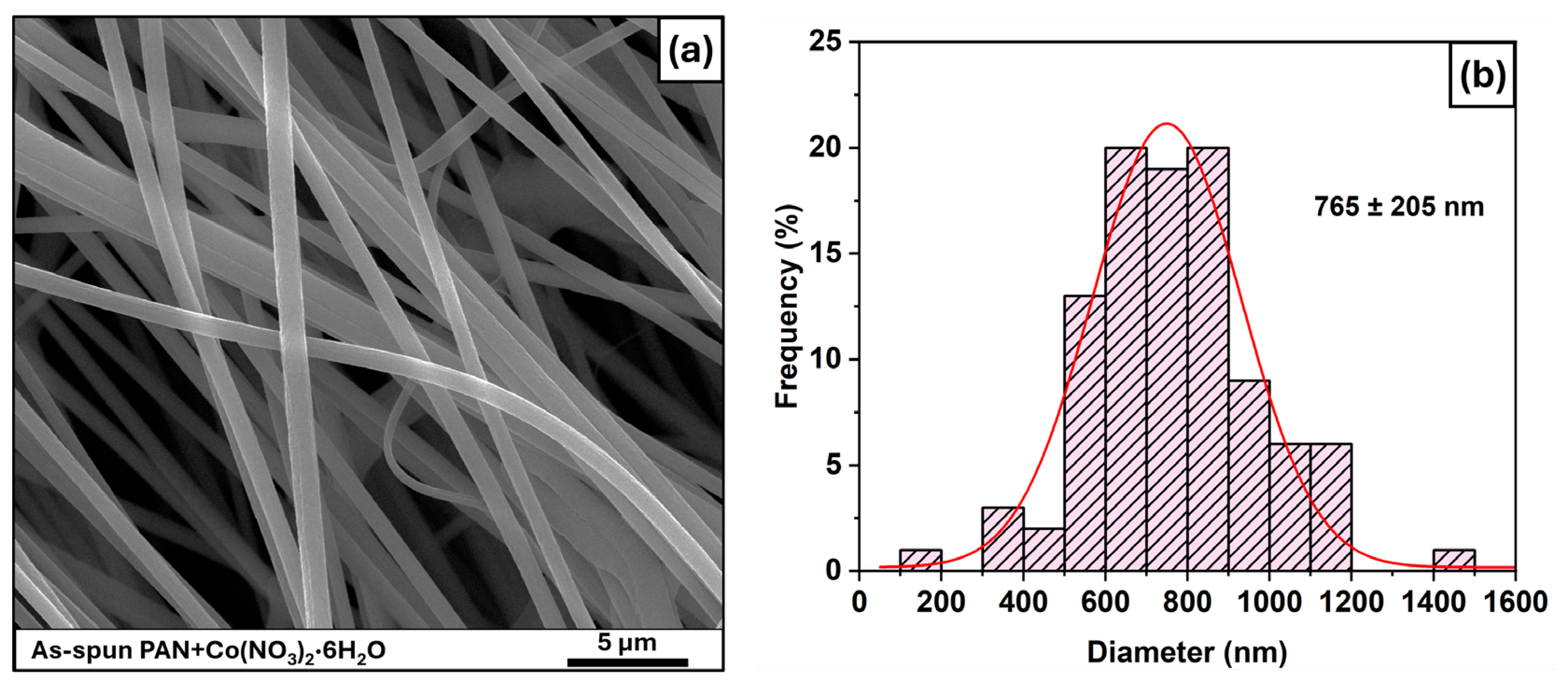
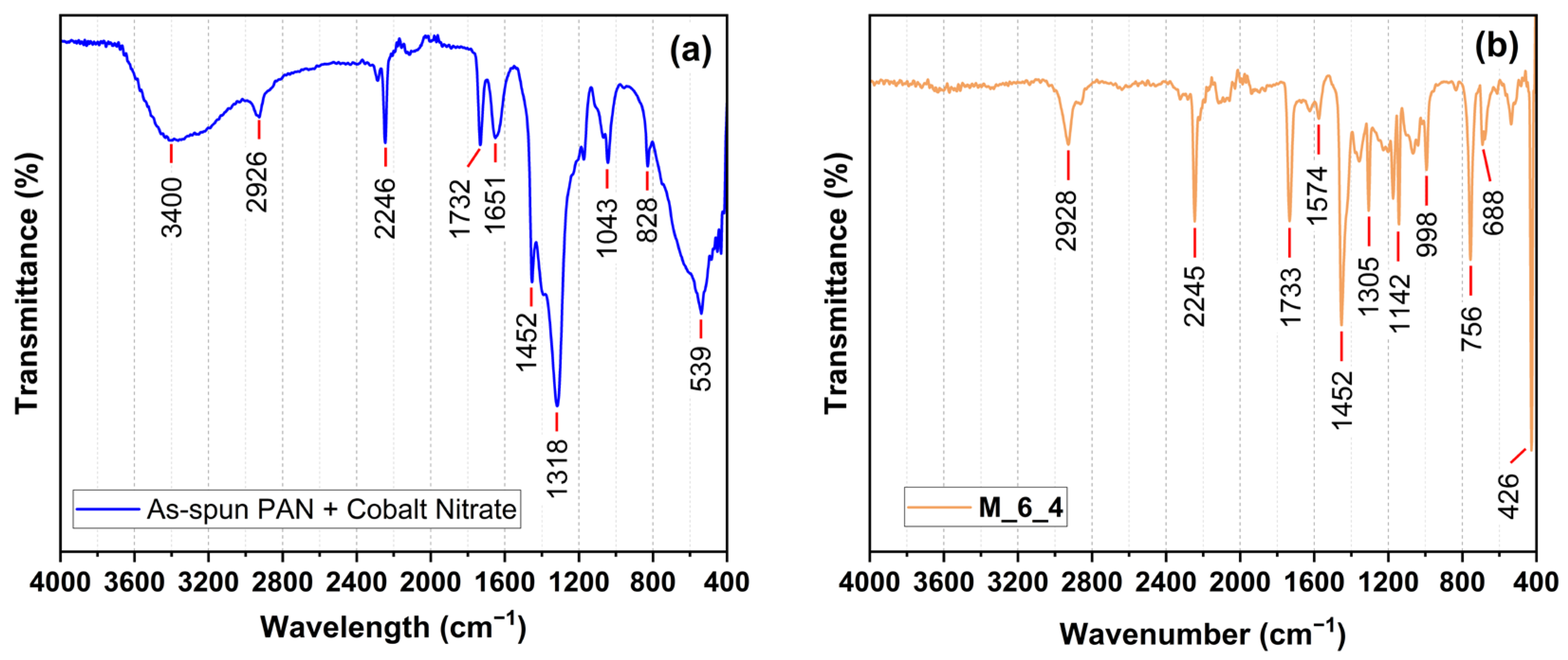
3.1. As-Spun Fibers

The as-spun fibers (before in situ growth) presented a uniform morphology, as can be seen in Figure 2a. Furthermore, the surface of the fibers presented a slight roughness (Figure S1) which occurs due to the presence of cobalt ions that cause viscoelastic instability during the electrospinning process [20]; such roughness can provide physical anchoring points for the MOF particles to be grown on fibers. The fiber diameter distribution, Figure 2b, shows that the fibers have diameters distributed between 200 nm and 1500 nm, with the average diameter being 765 ± 205 nm.
The FTIR spectrum (Figure 3a) shows a broad peak around 3400 cm−1, pertaining to the stretching of O-H bonds that are attributed to water from cobalt nitrate hexahydrate. The other bonds of cobalt nitrate are represented by the peaks at 1650 cm−1 (antisymmetric stretching of N=O), 1392 cm−1 (symmetric stretching of N=O), 826 cm−1 (out-of-plane bending of N-O) [21,22], and 539 cm−1, which is assigned to the Co-N interaction, indicating that cobalt is embedded into the PAN fibers. In addition, the FTIR spectra show peaks related to PAN and peaks that can be related to comonomers, which are commonly used in PAN synthesis. A summary of the peaks, bonds, and possible assignments can be seen in Table 2 [23].

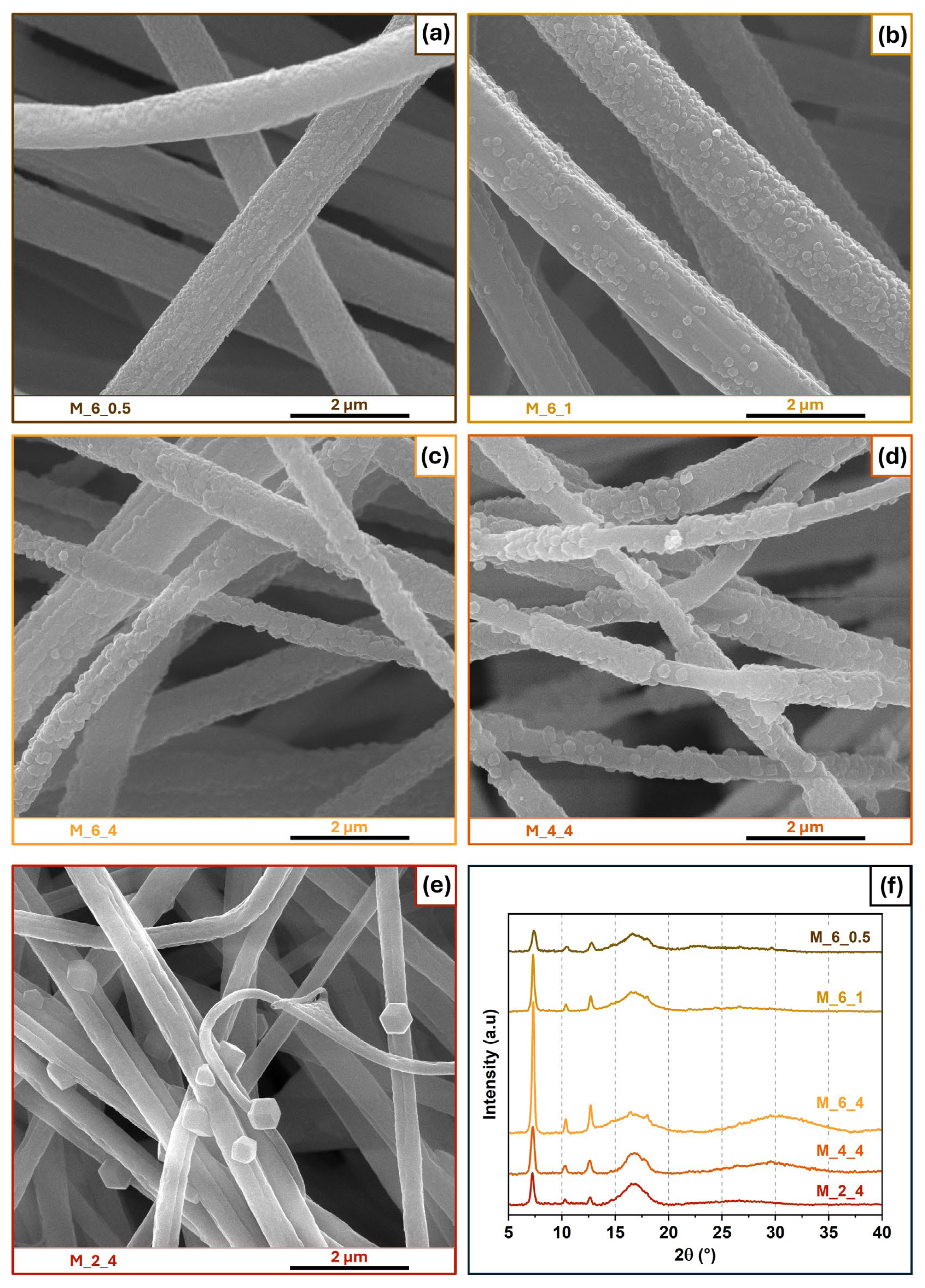
3.2. Influence of Time and Ligand Concentration

The growth kinetics and morphology of the MOFs synthesized by the in situ method depend on three main variables: the immersion time, the concentration of the linker in the liquid where the fibers will be immersed, and the type of liquid. In the first step of this work, the influence of time and the concentration of 2-MeIm (in either methanol or water) was analyzed.
After the in situ growth process in methanol, the FTIR spectrum presented some similarities and changes when compared to that of the as-spun fibers. Figure 3b shows that, for sample M_6_4 (see Table 1 for sample naming convention), the peaks related to PAN and the comonomer (2928, 2245, 1733, 1452, 1170, and 1064 cm−1) remained, indicating that the process did not lead to any change in the molecular structure of the polymer. Furthermore, the peaks for water (3400 cm−1) and nitrate (1650, 1366, 835, and 539 cm−1) disappeared or decreased significantly, indicating that they were removed during immersion. On the other hand, new peaks were observed, which were assigned to the 2-MeIm linker (1574 cm−1 of the C=N stretching and 1142, 998, 756, and 688 cm−1 for the out-of-plane bending and in-plane bending of the imidazole ring) [24]. The most important peak observed is the peak at 426 cm−1, which is attributed to the Co-N stretching between cobalt and nitrogen present in the 2-MeIm ligand. The presence of this peak indicates success in the synthesis of ZIF-67 [25]. The other samples prepared with methanol as a solvent (Figure S2a) presented the same peaks but with different intensities for the peaks related to ZIF-67, mainly for the peak around 420 cm−1 (Figure S2b). This indicates that this phase was formed in all conditions but with different characteristics.
In general, the crystallinity of MOFs and CO2 have a positive correlation: more crystalline MOFs present higher CO2 adsorption [26,27]. Previous work demonstrated that the area under the PXRD peak is a good indicator of the relative crystallinity [28,29,30], and this can be correlated with Avrami’s equation in a way to study the growth kinetics of the system. The relative crystallinity ( y ) is expressed by the following equation:
y = a r e a   u n d e r   t h e   c u r v e 011   p l a n e   a t   t i m e   t a r e a   u n d e r   t h e   c u r v e 011   p l a n e   a t   24   h
To evaluate the relative crystallinity of the samples, the area under peak for the plane (011) was calculated with Origin 2025 software. The PXRD patterns of 2ϑ from 6.5 to 8.0° of ZIF-67 crystals as a function of synthesis time can be seen in Figure S3. The kinetics of ZIF-67 growth followed Avrami’s classic model, which is expressed as follows: y = 1 e k t n , where k is a scaling constant, t is synthesis time, and n is the Avrami constant. This equation can be expressed in the linear form as follows: ln ln 1 y = ln k + n l n ( t ) . The experimental data for ZIF-67 agrees with Avrami’s model, as shown in Figure 4a,b.
The values of the two constants were k = 1.1 × 10⁻² min−n and n = 0.914. The value of k is a function of both the nucleation rate and growth rate; it is directly related to n and varies according to the temperature, solvent, and concentration used. The typical values of k for MOFs are in the range of 10−4 to 102 minn; in the case of ZIF-67, Feng et al. [28] obtained a value of k = 1.37 × 10⁻⁴ with synthesis at room temperature in methanol. In this work, a higher value indicates that the nucleation rate is very high or instantaneous, caused by PAN fibers that act as a surface for nucleation, characteristic of heterogeneous nucleation. The value of n can be written as n = n N + n G , where n N and n G represent the nucleation and growth components, respectively. In this case, since nucleation is instantaneous, nN can be neglected [31,32]. In diffusion-controlled growth with instantaneous nucleation ( n N = 0), which is the case of this work, the Avrami exponent values are n = 1.5, 1, and 0.5 for spherical, plate-like, and needle-like growth, respectively [31,32]. However, the particles formed did not present a plate- or needle-like morphology (Figure 5). This can be explained by the fact that the particles were limited initially by the fibers and later by other particles, hindering homogeneous growth in all directions.
To evaluate the influence of time on the growth of ZIF-67 particles in methanol, a constant concentration of 2-MeIm of 6.0 mg/mL was used. When immersed for only 0.5 h (Figure 5a), the sample presented a high number of particles with a granular morphology and an average size ± standard deviation of 57 ± 14 nm. The sample immersed for 1 h presented a similar number of particles but with a size of 88 ± 26 nm, and the largest particles had a prismatic shape (Figure 5b). When the immersion time was 4 h, the fibers were completely covered by particles that overlapped and presented an average size and standard deviation of 134 ± 34 nm (Figure 5c). The PXRD patterns displayed in Figure 5f show that all samples present a very well-defined peak at 2 ϑ = 7.3° related to the (011) plane of ZIF-67 [18], where sample M_6_4 presented the most intense peak. The presence of well-defined peaks at short synthesis times suggests that ZIF-67 crystals may evolve from a metastable phase [28].
The SEM images show the morphological evolution of the particles synthesized at different concentrations of 2-MeIm and immersed for 4 h. From the images, it is possible to observe that when the concentration of 2-MeIm was changed from 6 mg/mL (Figure 5c) to 4 mg/mL (Figure 5d), the size and shape of the particles did not change; however, the number of particles decreased, so the PAN fibers were no longer completely covered by ZIF-67. When the concentration was reduced to 2 mg/mL, the particles were slightly larger but in much smaller quantities (Figure 5e); this can be explained by the Ostwald ripening phenomenon, where larger particles grow at the expense of smaller particles. This indicates that the concentration of 2-MeIm has a major effect on the number of particles formed [33].
A constant concentration of 2-MeIm equal to 2.0 mg/mL was used to evaluate the influence of time on the growth of ZIF-67 particles in water. When water was used as a solvent, the particle morphology changed substantially in each condition. Figure 6a–c show samples W_2_0.5, W_2_1, and W_2_4, respectively. It was observed that after 0.5 h, small flakes were formed around the fibers; however, after 1 h, the particles presented diverse morphologies, including flakes, sheets, and granules. After 4 h, the in situ synthesis led to large flakes and sheets covering a large part of the PAN fibers. In some MOFs, polymorphism is possible with a variety of intermediates, ranging from amorphous gels to metastable crystalline phases [33,34]. Despite the different morphologies, PXRD (Figure 6f) shows few to no peaks of ZIF-67, while FTIR (Figure S4) shows Co-N peaks for all the samples. This confirms the existence of cobalt–imidazole pairs but not necessarily ZIF-67. The formation of MOFs requires a connection between metal ions/clusters and organic linkers with a suitable ratio and direction.
Figure 6c–e show the evolution of the morphology of the particles synthesized in different concentrations of 2-MeIm and immersed for 4 h. When the concentration increases from 2.0 mg/mL to 4.0 mg/mL, the particles become more uniform and have an appearance of scales/flakes around the entire surface of the fibers. At 6.0 mg/mL of 2-MeIm, the flocs disappear and become small granules, which are ZIF-67. Samples W_4_4 and W_6_4 are the only ones in Figure 6f that present a small peak at 2 ϑ = 7.3°, indicating that there is a small amount of ZIF-67 in them.
Water exhibits a high interfacial tension with the dissolved precursors, creating a higher surface barrier for crystallization and delaying nucleation. For this reason, samples in water could not grow to form the 3D ZIF-67 network under conditions with low 2-MeIm concentration and short synthesis time [35]. Other researchers observed that for ZIF-8, due to the high polarity of water, zinc ions have a greater tendency to react with the hydroxide group formed during the hydrolysis of water, rather than 2-methylimidazole. In this case, water acts as a ligand in the reaction and restricts the formation of the three-dimensional ZIF-8 crystal by forming a two-dimensional material [35].

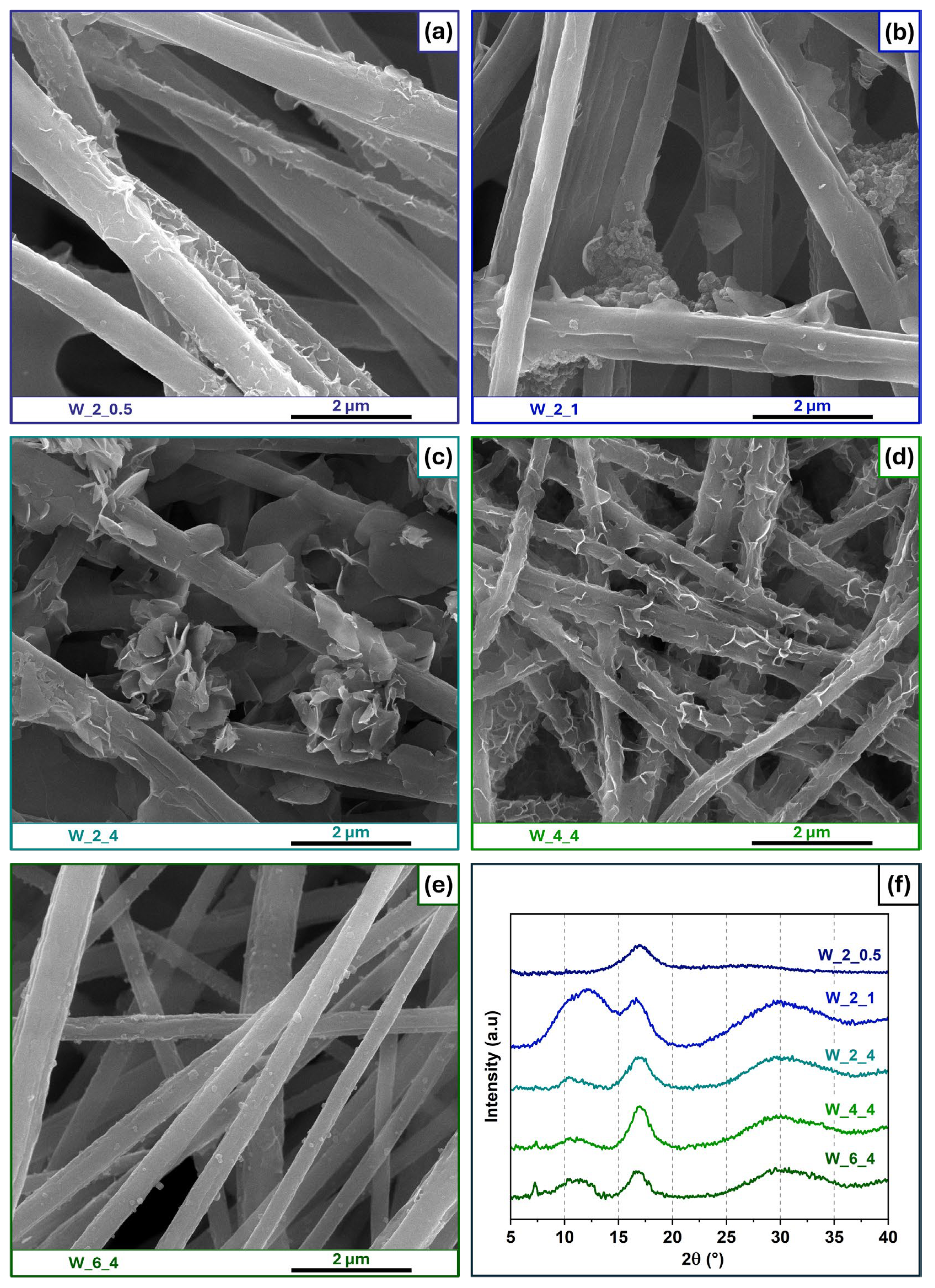
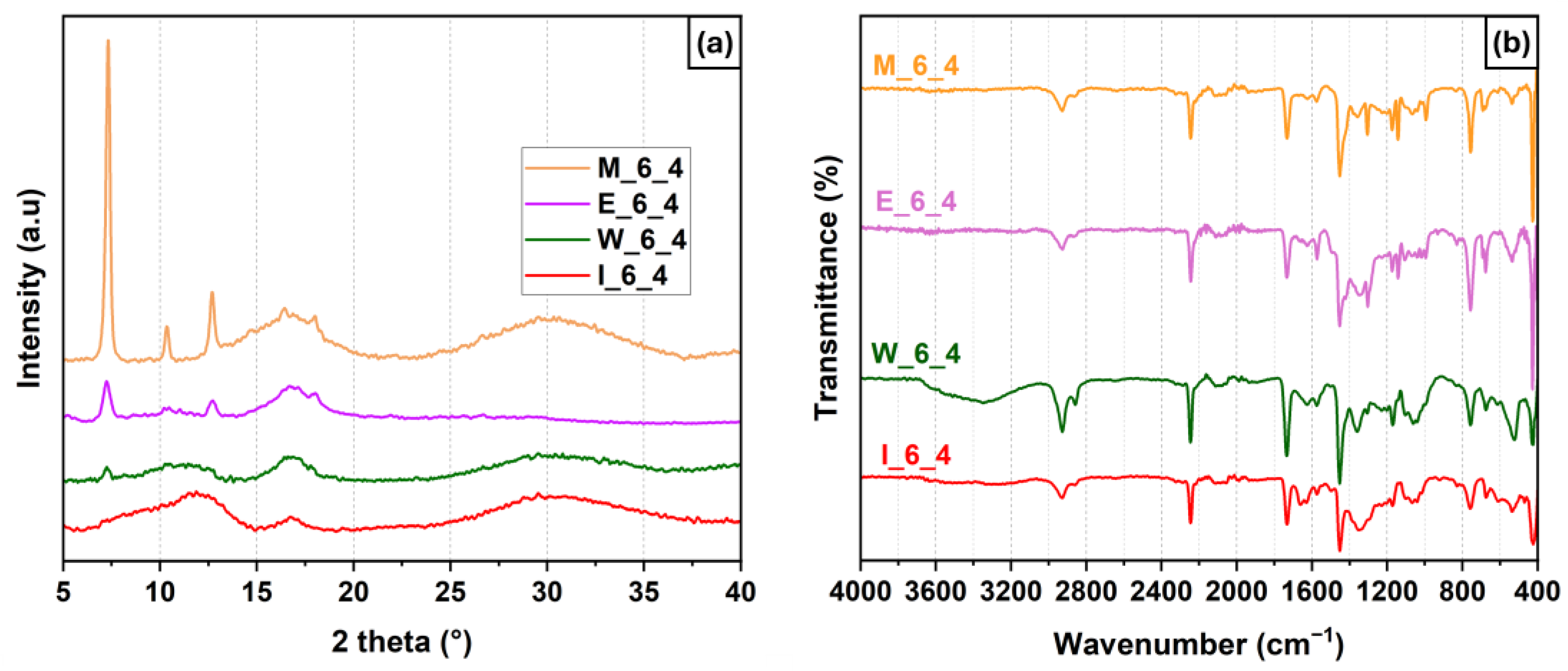
3.3. Influence of Solvent

For ZIF-67 synthesized using different solvents, the morphologies are significantly influenced by the polarity, viscosity, and solubility characteristics of each solvent, as observed in Figure 7.
When methanol is used as the solvent, its high polarity and low viscosity lead to the rapid nucleation of ZIF-67 crystals due to the deprotonation of methanol and the high diffusivity of Co2+ and 2-MeIm [35]. These characteristics result in uniform nanocrystals with well-defined polyhedral shapes that are very well distributed over the PAN fibers (Figure 7a). In contrast, ethanol, with a slightly lower polarity and higher viscosity than methanol, slows down the nucleation and growth rates. The formed particles presented irregular shapes (Figure 7b) instead of the polyhedral shape seen when methanol was used. Images in higher magnification can be found at Figure S5. Moreover, PXRD (Figure 8a) shows that all the peaks related to ZIF-67 are present for sample E_6_4, though with lower intensity than that for sample M_6_4.
Water, being highly polar and possessing high surface tension, produced a dramatically different result. The slow nucleation process in the aqueous condition led to a two-dimensional morphology mixed with small grain-like particles (Figure 7c). Furthermore, PXRD (Figure 8a) shows the presence of a small peak at 2 ϑ = 7.3° for sample W_6_4, which indicates the presence of a small amount of ZIF-67. The use of isopropanol introduced other differences due to its lower polarity and higher viscosity, which resulted in ZIF-67 not forming under the studied conditions. No crystalline peaks were observed for sample I_6_4 (Figure 7d).
The FTIR spectra (Figure 8b) corroborate the SEM and PXRD analyses; namely, the sample synthesized in methanol presents very intense peaks of ZIF-67 (especially the peak around 420 cm−1).
The CO2 adsorption isotherms for the pure PAN fibers and the samples synthesized with methanol, ethanol, water, and isopropanol are shown in Figure 9. The PAN fibers without any cobalt nitrate or ZIF-67 particles showed an adsorption close to 0.05 mmol/g at a pressure of 1.2 bar and 273 K. The samples with the lowest loading of ZIF-67 particles, I_6_4 and W_6_4, presented maximum adsorptions of 0.25 and 0.28 mmol/g, respectively, and even though these are low values, they are greater than that for pure PAN, suggesting that precursors have an influence on CO2 adsorption. Furthermore, the samples with more ZIF-67 particle formation (based on PXRD and FTIR) are the samples with higher CO2 adsorption capacities. Sample E_6_4 showed an adsorption of 0.36 mmol/g at a pressure of 1.2 bar, while sample M_6_4 presented an adsorption of 0.40 mmol/g. These results indicate that the presence of crystalline structures of ZIF-67 on PAN fibers significantly increases the adsorption of CO2. The complete isotherms (adsorption and desorption) in Figure S6 show that there is hysteresis in all samples, where the complete desorption of CO2 occurs when the pressure of the system is removed.
Besides the relatively low value for CO2 adsorption, when compared to other studies in the literature (Table 3), this work shows the importance of the solvent used during the synthesis of ZIF-67 on electrospun PAN fibers. Furthermore, this work can be highlighted for its simplicity and interesting value of CO2 obtained even with a low amount of MOF.

4. Conclusions

In this work, the influence of three factors on the in situ growth of ZIF-67 on electrospun PAN fibers was evaluated: synthesis time, 2-MeIm concentration, and solvent type.
It was observed that the use of methanol leads to more crystalline particles and that this effect is impaired at low synthesis times and low concentrations of 2-MeIm; the best result was obtained with the synthesis process using methanol as the solvent, 6.0 mg/mL of 2-MeIm, and a 4 h duration; particles with a polyhedral shape and dimensions around 130 nm were formed, which were highly crystalline and completely covering the PAN fibers.
When ethanol was used, a very thin layer of ZIF-67 particles, without a regular shape, was formed uniformly on the PAN fibers. The use of water as a solvent led to a mixture of morphologies according to the synthesis condition, with particles in the shape of sheets, flakes, and grains being obtained. On the other hand, the use of isopropanol did not lead to the formation of particles on the fibers.
Regarding CO2 adsorption, the samples with the highest number of particles (synthesized with methanol and ethanol) presented higher adsorption values of 0.40 and 0.36 mmol/g, respectively, at 273 K and a pressure of 1.2 bar. In comparison, pure PAN fibers presented an adsorption of only 0.05 mmol/g, showing that the in situ growth of ZIF-67 on PAN results in better CO2 adsorption.

Supplementary Materials

The following supporting information can be downloaded at https://www.mdpi.com/article/10.3390/fib13050050/s1, Figure S1: SEM image at different magnifications of as-spun PAN + Co(NO3)2·6 H2O fibers. Figure S2: FTIR spectra of the samples synthesized via immersion in methanol under different conditions. Figure S3: PXRD peak related to the (011) plane of samples synthesized in methanol, 6.0 mg/mL of 2-MeIm at different times. Figure S4: FTIR spectra of the samples synthesized via immersion in water under different conditions. Figure S5: SEM images at lower magnification of fibers after immersed for 4 h in (a) methanol, (b) ethanol, (c) water, and (d) isopropanol. (2-MeIm concentration of 6.0 mg/mL). Figure S6: CO2 adsorption and desorption isotherms for the samples synthesized with methanol, ethanol, water, and isopropanol.

Author Contributions

Conceptualization, G.H.F.M.; methodology, G.H.F.M. and T.Y.; validation, G.H.F.M., Y.L. and U.S.; formal analysis, G.H.F.M. and T.Y.; investigation, G.H.F.M.; resources, U.S.; data curation, G.H.F.M.; writing—original draft preparation, G.H.F.M.; writing—review and editing, T.Y., Y.L. and U.S.; visualization, G.H.F.M.; supervision, U.S.; project administration, G.H.F.M. and U.S.; funding acquisition, U.S. All authors have read and agreed to the published version of the manuscript.

Funding

This research was funded by Natural Sciences and Engineering Research Council of Canada (NSERC) grant number [05503/2020].

Data Availability Statement

The original contributions presented in this study are included in the article. Further information can be provided upon request to the corresponding author.

Acknowledgments

We would like to thank Natural Sciences and Engineering Research Council of Canada (NSERC) grant number 05503/2020 for funding and NSERC Undergraduate Student Research Award (Tiffany Yau), Alberta Innovates for graduate scholarship (Guilherme Melo), and Nicholas Fylstra for helping in the CO2 adsorption analysis.

Conflicts of Interest

The authors declare no conflicts of interest.

References

  1. NOAA Research No Sign of Greenhouse Gases Increases Slowing in 2023. Available online: https://research.noaa.gov/no-sign-of-greenhouse-gases-increases-slowing-in-2023/ (accessed on 30 March 2025).
  2. National Grid What Is CCS and How Does It Work? Available online: https://www.nationalgrid.com/stories/energy-explained/what-is-ccs-how-does-it-work (accessed on 30 March 2025).
  3. Congressional Budget Office Carbon Capture and Storage in the United States. Available online: https://www.cbo.gov/publication/59832 (accessed on 30 March 2025).
  4. Bhavsar, A.; Hingar, D.; Ostwal, S.; Thakkar, I.; Jadeja, S.; Shah, M. The Current Scope and Stand of Carbon Capture Storage and Utilization—A Comprehensive Review. Case Stud. Chem. Environ. Eng. 2023, 8, 100368. [Google Scholar] [CrossRef]
  5. Li, D.; Yadav, A.; Zhou, H.; Roy, K.; Thanasekaran, P.; Lee, C. Advances and Applications of Metal-Organic Frameworks (MOFs) in Emerging Technologies: A Comprehensive Review. Glob. Chall. 2024, 8, 2300244. [Google Scholar] [CrossRef] [PubMed]
  6. Zhu, Y.-J.; Chen, F.-F. Microwave Synthesis of Nanomaterials. Encycl. Nanomater. 2023, 1, 48–63. [Google Scholar] [CrossRef]
  7. Duan, C.; Yu, Y.; Hu, H. Recent Progress on Synthesis of ZIF-67-Based Materials and Their Application to Heterogeneous Catalysis. Green Energy Environ. 2022, 7, 3–15. [Google Scholar] [CrossRef]
  8. Saeed, S.; Bashir, R.; Rehman, S.U.; Nazir, M.T.; ALOthman, Z.A.; Muteb Aljuwayid, A.; Abid, A.; Adnan, A. Synthesis and Characterization of ZIF-67 Mixed Matrix Nanobiocatalysis for CO2 Adsorption Performance. Front. Bioeng. Biotechnol. 2022, 10, 891549. [Google Scholar] [CrossRef]
  9. Pan, Y.; Li, H.; Zhang, X.-X.; Zhang, Z.; Tong, X.-S.; Jia, C.-Z.; Liu, B.; Sun, C.-Y.; Yang, L.-Y.; Chen, G.-J. Large-Scale Synthesis of ZIF-67 and Highly Efficient Carbon Capture Using a ZIF-67/Glycol-2-Methylimidazole Slurry. Chem. Eng. Sci. 2015, 137, 504–514. [Google Scholar] [CrossRef]
  10. Li, D.; Xia, Y. Electrospinning of Nanofibers: Reinventing the Wheel? Adv. Mater. 2004, 16, 1151–1170. [Google Scholar] [CrossRef]
  11. Shin, Y.M.; Hohman, M.M.; Brenner, M.P.; Rutledge, G.C. Experimental Characterization of Electrospinning: The Electrically Forced Jet and Instabilities. Polymer 2001, 42, 09955–09967. [Google Scholar] [CrossRef]
  12. Cramariuc, B.; Cramariuc, R.; Scarlet, R.; Manea, L.R.; Lupu, I.G.; Cramariuc, O. Fiber Diameter in Electrospinning Process. J. Electrostat. 2013, 71, 189–198. [Google Scholar] [CrossRef]
  13. Fong, H.; Chun, I.; Reneker, D.H. Beaded Nanofibers Formed during Electrospinning. Polymer 1999, 40, 4585–4592. [Google Scholar] [CrossRef]
  14. Melo, G.H.F.; Sundararaj, U. Influence of Mixed Solvent in the Morphology and Hydrophobicity of Electrospun Polystyrene Porous Fibers. Macromol. Rapid Commun. 2024, 45, e2400403. [Google Scholar] [CrossRef] [PubMed]
  15. Ahmadi Bonakdar, M.; Rodrigue, D. Electrospinning: Processes, Structures, and Materials. Macromol 2024, 4, 58–103. [Google Scholar] [CrossRef]
  16. Ince Yardimci, A.; Yagmurcukardes, N.; Yagmurcukardes, M.; Capan, I.; Erdogan, M.; Capan, R.; Tarhan, O.; Acikbas, Y. Electrospun Polyacrylonitrile (PAN) Nanofiber: Preparation, Experimental Characterization, Organic Vapor Sensing Ability and Theoretical Simulations of Binding Energies. Appl. Phys. A 2022, 128, 173. [Google Scholar] [CrossRef]
  17. Zhao, R.-X.; Sun, P.; Liu, R.; Ding, Z.; Li, X.; Liu, X.; Zhao, X.; Gao, Z. Influence of Heating Procedures on the Surface Structure of Stabilized Polyacrylonitrile Fibers. Appl. Surf. Sci. 2018, 433, 321–328. [Google Scholar] [CrossRef]
  18. Melo, G.H.F.; Liu, Y.; Sundararaj, U. In Situ Growth of ZIF-67 Particles on PVDF Electrospun Nanofibers. Fibers Polym. 2024, 25, 3293–3306. [Google Scholar] [CrossRef]
  19. Schneider, C.A.; Rasband, W.S.; Eliceiri, K.W. NIH Image to ImageJ: 25 Years of Image Analysis. Nat. Methods 2012, 9, 671–675. [Google Scholar] [CrossRef]
  20. Angammana, C.J.; Jayaram, S.H. Analysis of the Effects of Solution Conductivity on Electrospinning Process and Fiber Morphology. IEEE Trans. Ind. Appl. 2011, 47, 1109–1117. [Google Scholar] [CrossRef]
  21. Chen, Y.; Wang, S.; Li, Z. A Cobalt–Pyrrole Coordination Compound as High Performance Cathode Catalyst for Direct Borohydride Fuel Cells. RSC Adv. 2020, 10, 29119–29127. [Google Scholar] [CrossRef]
  22. Mashao, G.; Modibane, K.D.; Mdluli, S.B.; Iwuoha*, E.I.; Hato, M.J.; Makgopa, K.; Molapo, K.M. Polyaniline-Cobalt Benzimidazolate Zeolitic Metal-Organic Framework Composite Material for Electrochemical Hydrogen Gas Sensing. Electrocatalysis 2019, 10, 406–419. [Google Scholar] [CrossRef]
  23. Cetiner, S.; Sen, S.; Arman, B.; Sarac, A.S. Acrylonitrile/Vinyl Acetate Copolymer Nanofibers with Different Vinylacetate Content. J. Appl. Polym. Sci. 2013, 127, 3830–3838. [Google Scholar] [CrossRef]
  24. Naghshbandi, Z.; Gholinejad, M.; Sansano, J.M.; Eskandari, M. Graphene Quantum Dots Incorporated ZIF-67 for Stabilization of Au Nanoparticles: Efficient Catalyst for A3-coupling and Nitroarenes Reduction Reactions. Appl. Organomet. Chem. 2024, 38, e7400. [Google Scholar] [CrossRef]
  25. Nagshbandi, Z.; Gholinejad, M.; Sansano, J.M. Novel Magnetic Zeolitic Imidazolate Framework for Room Temperature Enhanced Catalysis. Inorg. Chem. Commun. 2023, 150, 110463. [Google Scholar] [CrossRef]
  26. Frentzel-Beyme, L.; Kloß, M.; Pallach, R.; Salamon, S.; Moldenhauer, H.; Landers, J.; Wende, H.; Debus, J.; Henke, S. Porous Purple Glass—A Cobalt Imidazolate Glass with Accessible Porosity from a Meltable Cobalt Imidazolate Framework. J. Mater. Chem. A Mater. 2019, 7, 985–990. [Google Scholar] [CrossRef]
  27. Ma, M.; Zhou, A.; Hong, T.; Jia, X.; Liu, M. Tailored Porous Structure and CO2 Adsorption Capacity of Mg-MOF-74 via Solvent Polarity Regulation. Chem. Eng. J. 2023, 476, 146845. [Google Scholar] [CrossRef]
  28. Feng, X.; Carreon, M.A. Kinetics of Transformation on ZIF-67 Crystals. J. Cryst. Growth 2015, 418, 158–162. [Google Scholar] [CrossRef]
  29. Feng, X.; Wu, T.; Carreon, M.A. Synthesis of ZIF-67 and ZIF-8 Crystals Using DMSO (Dimethyl Sulfoxide) as Solvent and Kinetic Transformation Studies. J. Cryst. Growth 2016, 455, 152–156. [Google Scholar] [CrossRef]
  30. Venna, S.R.; Jasinski, J.B.; Carreon, M.A. Structural Evolution of Zeolitic Imidazolate Framework-8. J. Am. Chem. Soc. 2010, 132, 18030–18033. [Google Scholar] [CrossRef]
  31. Cantor, B. The Equations of Materials; Oxford University Press: Oxford, UK, 2020; ISBN 9780191886683. [Google Scholar]
  32. Shirzad, K.; Viney, C. A Critical Review on Applications of the Avrami Equation beyond Materials Science. J. R. Soc. Interface 2023, 20, 20230242. [Google Scholar] [CrossRef]
  33. Van Vleet, M.J.; Weng, T.; Li, X.; Schmidt, J.R. In Situ, Time-Resolved, and Mechanistic Studies of Metal–Organic Framework Nucleation and Growth. Chem. Rev. 2018, 118, 3681–3721. [Google Scholar] [CrossRef]
  34. Rimer, J.D.; Tsapatsis, M. Nucleation of Open Framework Materials: Navigating the Voids. MRS Bull. 2016, 41, 393–398. [Google Scholar] [CrossRef]
  35. Akhundzadeh Tezerjani, A.; Halladj, R.; Askari, S. Different View of Solvent Effect on the Synthesis Methods of Zeolitic Imidazolate Framework-8 to Tuning the Crystal Structure and Properties. RSC Adv. 2021, 11, 19914–19923. [Google Scholar] [CrossRef]
  36. Choi, C.; Kadam, R.L.; Gaikwad, S.; Hwang, K.-S.; Han, S. Metal Organic Frameworks Immobilized Polyacrylonitrile Fiber Mats with Polyethyleneimine Impregnation for CO2 Capture. Microporous Mesoporous Mater. 2020, 296, 110006. [Google Scholar] [CrossRef]
  37. Zhang, Y.; Zhang, Y.; Wang, X.; Yu, J.; Ding, B. Ultrahigh Metal–Organic Framework Loading and Flexible Nanofibrous Membranes for Efficient CO2 Capture with Long-Term, Ultrastable Recyclability. ACS Appl. Mater. Interfaces 2018, 10, 34802–34810. [Google Scholar] [CrossRef]
  38. Mo, J.; Hu, D.; Liu, X.; Sun, Y.; Li, X.; Wang, C.; Chai, B.; Ding, D.; Yan, J.; Sun, L. Eco-Friendly ZIF-67/Rice Straw-Derived Cellulose Acetate Electrospun Nanofiber Mats for Efficient CO2 Capturing and Selectivity Removal of Methyl Orange Dye. J. Environ. Chem. Eng. 2022, 10, 108989. [Google Scholar] [CrossRef]
  39. Li, C.; He, N.; Zhao, X.; Zhang, X.; Li, W.; Zhao, X.; Qiao, Y. Chitosan/ZIF-8 Composite Beads Fabricated by In Situ Growth of MOFs Crystals on Chitosan Beads for CO2 Adsorption. ChemistrySelect 2022, 7, e202103927. [Google Scholar] [CrossRef]
  40. Gaikwad, R.; Gaikwad, S.; Han, S. Piperazine-Loaded Electrospun Fiber Mats with MIL-101(Cr, Mg) Metal Organic Framework for CO2 Capture. J. Environ. Chem. Eng. 2023, 11, 111592. [Google Scholar] [CrossRef]
Figure 1. Schematic representation of in situ synthesis of ZIF-67 on electrospun PAN fibers. (The red arrow represents the collector’s rotation).
Fibers 13 00050 g001
Figure 2. (a) SEM image and (b) diameter distribution of as-spun PAN + Co(NO3)2·6 H2O fibers.
Fibers 13 00050 g002
Figure 3. FTIR spectra of (a) as-spun PAN + Co(NO3)2·H2O fibers and (b) ZIF-67@PAN fibers (sample M_6_4).
Fibers 13 00050 g003
Figure 4. (a) Linear and (b) exponential Avrami fitting for relative crystallinity for samples synthesized in methanol with 6.0 mg/mL of 2-MeIm at different times. (Dotted line indicates the time of 4 h).
Fibers 13 00050 g004
Figure 5. SEM images and PXRD plot of samples synthesized via immersion in methanol under different conditions. (a) M_6_0.5, (b) M_6_1, (c) M_6_4, (d) M_4_4, (e) M_2_4, and (f) PXRD patterns.
Fibers 13 00050 g005
Figure 6. SEM images and PXRD plot of samples synthesized via immersion in water under different conditions. (a) W_2_0.5, (b) W_2_1, (c) W_2_4, (d) M_4_4, (e) M_6_4, and (f) PXRD patterns.
Fibers 13 00050 g006
Figure 7. SEM images of fibers after being immersed for 4 h in (a) methanol, (b) ethanol, (c) water, and (d) isopropanol. (2-MeIm concentration of 6.0 mg/mL).
Fibers 13 00050 g007
Figure 8. (a) PXRD pattern and (b) FTIR spectra of samples immersed for 4 h in different solvents. (2-MeIm concentration of 6.0 mg/mL).
Fibers 13 00050 g008
Figure 9. CO2 adsorption isotherms for the as-spun fibers and the samples synthesized with methanol, ethanol, water, and isopropanol. (a) from 0 to 1.2 bar; (b) amplification of (a), from 0 to 0.2 bar.
Fibers 13 00050 g009
Table 1. Labeling of samples according to synthesis conditions.
Solvent2-MeIm Concentration (mg/mL)Time (h)Sample Name
Methanol60.5M_6_0.5
Methanol61M_6_1
Methanol64M_6_4
Methanol44M_4_4
Methanol24M_2_4
Water20.5W_2_0.5
Water21W_2_1
Water24W_2_4
Water44W_4_4
Water64W_6_4
Ethanol64E_6_4
Isopropanol64I_6_4
Table 2. The identification of the FTIR peaks present on the as-spun fibers and ZIF-67@PAN samples.
As-Spun FiberZIF-67@PAN
Frequency (cm−1)BondAssignmentBondAssignment
3400O-HH2O--
2926C-HPAN–comonomerC-HPAN–comonomer
2246C≡NPANC≡NPAN
1732C=OComonomerC=OComonomer
1651N=OCobalt nitrate--
1572--C=NZIF-67
1452C-HPANC-HPAN
1392N=OCobalt nitrate--
1318C=OComonomerC=OComonomer
1170C-OComonomerC-OComonomer
1141--Imidazole ringZIF-67
1043C-O-CPAN–comonomerC-O-CPAN–comonomer
998--Imidazole ringZIF-67
828N-OCobalt nitrate--
756--Imidazole ringZIF-67
688--Imidazole ringZIF-67
539Co-OCobalt nitrateCo-OCobalt nitrate
426--Co-NZIF-67
Table 3. Comparison of CO2 adsorption in different works using MOFs and polymers through different integration methods.
MOFPolymerWeight ContentIntegration MethodCO2 Capacity (mmol/g)Temperature [K]Reference
ZIF-67PAN2%In situ growth on nanofibers0.40273This work
ZIF-67PSU3%Solution casting0.50273[8]
ZIF-8PAN60%Direct electrospinning0.55298[36]
HKUST-1PAN60%Direct electrospinning2.55298[36]
HKUST-1PAN82%Direct electrospinning + Secondary growth3.90298[37]
ZIF-67RSCA-In situ growth on nanofibers1.33273[38]
ZIF-8Chitosan-In situ growth on beads≈0.70275[39]
MIL-101PAN70%Direct electrospinning1.00298[40]
Disclaimer/Publisher’s Note: The statements, opinions and data contained in all publications are solely those of the individual author(s) and contributor(s) and not of MDPI and/or the editor(s). MDPI and/or the editor(s) disclaim responsibility for any injury to people or property resulting from any ideas, methods, instructions or products referred to in the content.

