Abstract
In this work, poly(ethersulfone) (PES) ultrafiltration (UF) hollow fibers (HF) were modified by introducing TiO2 nanoparticles (TiO2-NPs) in the polymeric dope, to endow them with photocatalytic properties. Different dope compositions and spinning conditions for producing “blank” PES UF fibers with suitable properties were investigated. PEO–PPO–PEO (Poly(ethylene glycol)-block-poly(propylene glycol)-block-poly(ethylene glycol, Pluronic® (Sigma-Aldrich, Milan, Italy) was finally selected as the additive and a suitable dope composition was identified. After the detection of an appropriate dope composition and the optimization of the spinning parameters, PES-TiO2 HF was produced. The optimized composition was employed for preparing the mixed matrix HF loaded with TiO2 NPs. The effect of different TiO2 NP (0.3–1 wt %) concentrations and bore fluid compositions on the fiber morphology and properties were explored. The morphology of the produced fibers was analyzed by Scanning Electron Microscopy (SEM). Fibers were further characterized by measuring: pore size diameters and thickness, porosity, and pure water permeability (PWP). The photocatalytic activity of the new membranes was also tested by UV light irradiation. The model “foulant” methylene blue (MB) was used in order to prove the efficiency of the novel UF membrane for dye photo-degradation.
1. Introduction
Today, pollution, depletion of fossil fuels, and gradual reduction of drinking water sources are among the most dire emergencies afflicting our planet, especially considering the simultaneous increase in the population. There is no single solution to tackle these serious problems that are afflicting modern society. Nevertheless, it is possible to realize positive strategies, based on collaboration between the scientific community, political and economic authorities, and the population in general. In this scenario, membrane technologies represent an excellent starting point for implementing these strategies. The advantages of membrane technologies and processes are now widely accepted. Far from being confined within the walls of a laboratory, membrane applications have become widespread in industry, and have even started to enter into our family homes; for example, with the growing popularity of home water purification systems. Especially concerning water treatment, membrane based pressure driven operations (i.e., micro-, ultra-, nanofiltration, and reverse osmosis), together with membrane reactors, contactors, and integrated membrane systems, are generally acknowledged as suitable, reliable, sustainable, and cost-effective alternatives to traditional filtration, purification, and desalination procedures [1,2,3]. The heart of each process is the membrane itself, along with its performance, often expressed in terms of flux and selectivity.
Other aspects that are equally important concern the chemical and mechanical resistance and, above all, the susceptibility to fouling. Fouling and, especially, biofouling, is a major drawback of any membrane process; indeed, the latter is often referred as its “Achilles’ heel” [4]. It impairs membrane performance (flux decline) and forces us to stop processes to carry out membrane cleaning or module replacement, leading to discontinuity in operation, reduction of the membrane lifetime, and to the increase of costs. Although this problem cannot be completely eliminated, a set of strategies can significantly reduce its effects, moving the balance needle towards the pros, rather than cons, of membrane processes. Different approaches are currently under investigation, from research on new membrane materials and testing of innovative preparation techniques, to the optimization of module and plant configuration. Among all the possible strategies, tailoring the membrane material and properties is a fundamental basis of any process, which might be further improved. Furthermore, as recently pointed by Jhaveri and Murthy [5], irreversible fouling, which leads to permanent flux decline, can only be reduced by modification of the membrane preparation techniques.
Several studies have highlighted the possibility of drastically reducing membrane susceptibility to fouling by modifying well-known conventional polymers (i.e., PES, PSf, PVDF, and PVC) using nanoparticles (NPs) or the composites of nanoparticles [5]. Both mixed matrix and thin-film nanocomposite membranes can be prepared. In the first case, NPs are dispersed into the polymer casting solution before the phase inversion step; in the second case, NPs self-assemble onto the membrane surface via dip-coating or other methods. Different nano-sized materials can be used for this purpose, such as metal and metal-oxide NPs, zeolites, carbon-based nanomaterials (nanotubes, graphene, graphene oxide), or even combined hybrid nanomaterials (GO–SiO2, GO–TiO2) [6,7,8,9,10,11,12].
Even though nanoparticle composite membranes have recently shown promising results [13], titanium dioxide (TiO2) still retains much attention due to its outstanding photo-catalytic and antibacterial properties that are coupled to stability, high hydrophilicity, non-toxicity, biocompatibility, and low cost [14].
Concerning polymeric membrane materials, the sulfone family, and, in particular, polyethersulfone (PES), is among the leading choices for the preparation of both flat sheets and hollow fibers. PES has the highest hydrophilicity, due to its highest percentage of sulfone groups, together with good stability and resistance, ease of processing, and compatibility with several additives. Indeed, PES was widely used in the past for the preparation of membranes for several purposes [15,16,17,18,19,20]; it is still under investigation for the preparation of polymer/TiO2 nanocomposite membranes.
Both the incorporation of NPs in the membrane matrix and coating on the membrane surface were investigated, and in general resulted in increased hydrophilicity, sustained photocatalytic activity, and improved resistance to fouling. The most relevant results of the recent works on PES/TiO2 membrane preparation are shown in Table 1; papers are divided in two categories, depending on the strategy employed for NP immobilization (incorporation in the membrane matrix vs. deposition onto its surface).

Table 1.
Recent publications on PES-TiO2 membrane preparation.
Li et al. [21] reported the preparation of (PES)/TiO2 membranes by combining the Vapor Induced and Diffusion Induced Phase Separation techniques (VIPS and DIPS). The prepared membranes showed improved hydrophilicity and water permeability; furthermore, the authors found that the optimal TiO2 concentration was around 1%–2%. Vatanpour et al. [24] observed that susceptibility to biofouling of PES nanofiltration membranes was reduced by the addition of TiO2 particles; a water flux recovery percentage of 90.8% after whey filtration was achieved using membranes containing 20 nm particles. Similarly, lower protein adsorption, sustained photocatalytic activity, and long-term hydrophilicity, coupled to an increase in flux recovery after filtration of humic acid, were reported by Razmjou et al. [29] for PES membranes modified by a coating with TiO2 nanoparticles.
Even though several papers reported the preparation of TiO2 nanocomposite flat membranes, to the authors’ best knowledge, few works have investigated the possibility of preparing polymer/TiO2 hollow fibers. As it is widely accepted that the preparation of hollow fibers is more difficult with respect to flat membranes, it is equally acknowledged that this configuration offers several advantages. Indeed, hollow fiber modules ensure space savings (higher surface to volume ratio), higher productivity, and ease of maintenance, as they can be back-flushed [32].
Interesting results have been reported so far by using poly(vinylidene fluoride) (PVDF) as a polymer material [33,34,35,36]. Dzinun et al. recently achieved remarkable photocatalytic properties, by preparing double layer PVDF/PVDF-TiO2 hollow fiber membranes [37,38]. In contrast, only a few works investigated the preparation of PES/TiO2 hollow fibers (Razmjou et al. [25], Zhang et al. [39]). PES is more suitable than PVDF as a polymeric material for preparing membranes for water treatment, due to its higher intrinsic hydrophilicity. Furthermore, PES membranes exhibit very low protein binding and represent the leading choice for filtering cell culture media. On the other hand, PVDF has a much higher chemical resistance and oxidative stability, which makes the membrane more durable under different conditions.
In this work, nanocomposite PES/TiO2 hollow fiber membranes were prepared by the dry/wet phase inversion technique. First, blank PES fibers were produced, in order to optimize the polymeric dope composition and, hence, the fiber properties themselves. Based on the obtained results, one dope solution composition was selected and the effect of TiO2 concentration on the fiber morphology and properties was investigated. The prepared fibers were characterized by several techniques, including its water permeability. Bare PES and PES/TiO2 hollow fiber properties were analyzed and compared. The photocatalytic activity of the new membranes was also tested by UV light irradiation using the model “foulant”, methylene blue (MB).
2. Materials and Methods
2.1. Dope Viscosity Measurements
The viscosity of the dope solutions prepared using different additives was measured using a Brookfield programmable rheometer (DV-III Ultra) (Brookfield, Middleboro, MA, USA) equipped with a thermostatic bath. Measurements were carried out as described elsewhere [40], within a range of Torque between 10% and 90%. A first set of experiments was carried out at 85 °C, measuring viscosity as a function of the shear rate. A second group of measurements was performed in order to study the effect of temperature on the viscosity of the selected dopes. The compositions of the dope solutions prepared for viscosity measurements are listed in Table 2.
Table 2.
Compositions of the polymeric dopes used in the viscosity measurements.
2.2. Polymeric Dope Preparation, Hollow Fiber Spinning, and Post-Treatment
PES Ultrason E6020P was kindly supplied by BASF-Italia (Cesano Maderno, Italy). N-methylpyrrolidone (NMP), poly(ethylene glycol) (PEG) 400, and Pluronic® F-127 (hereinafter named simply as Plu) were purchased from Sigma-Aldrich (Sigma-Aldrich, Milan, Italy ). Poly(vinyl pyrrolidone) (PVP), Luviskol K-17, and K-30 were purchased from BASF. The TiO2-NPs suspension in NMP was kindly provided by LEITAT (Terrassa, Spain). The size of the nanoparticles, measured in solution with dynamic light scattering (DLS), was between 60 and 100 nm.
Polymeric dopes were prepared by adding components to the solvent under continuous stirring, at constant temperature. Prior to any spinning experiment, dope solutions were allowed to degas overnight, in order to eliminate air bubbles. The composition of the dopes used for the spinning experiments are listed in Table 3. Hollow fibers were produced as described elsewhere [20,40,41,42], by the dry/wet technique. Detailed spinning conditions of each experiment are reported in Table 4.
Table 3.
Composition of polymeric dopes used in the spinning experiments.
Table 4.
Detailed conditions of the spinning experiments. Outer diameter (O.D.)/Inner diameter (I.D.).
The produced hollow fibers were kept in a frequently refreshed water bath for 1 day, in order to ensure complete coagulation and remove residual solvent. Then, they were soaked in a glycerol aqueous solution, with a concentration of 30 wt %, for 3–4 h, before drying, in order to avoid the collapse of their porous structure, as previously described elsewhere [20,40,41,42].
2.3. Fiber Morphology Characterization
The elemental analyses and the morphology of the produced PES hollow fibers were evaluated by Energy Dispersive X-ray spectroscopy (EDX) and by Scanning Electron Microscopy (SEM) (EVO|MA 10, Zeiss, Milan, Italy). Fiber cross sections were prepared by freezing fractions in liquid nitrogen; the morphology of the inner and outer surfaces was also analyzed. Pictures were acquired working in high-vacuum mode. For SEM observation, samples were covered with a thin layer of gold before observation, using a gold-sputter (Quorum Q150 RS) (Quorum Technlogies, Lewes, UK). Fiber diameters (Outer and Inner, O.D. and I.D) and thickness were measured from the acquired SEM pictures; the obtained data were compared to those acquired manually by a digital micrometer.
2.4. Fiber Porosity
Fiber porosity, εm, was calculated by measuring the void fraction, i.e., is the volume of the pores divided by the total volume of the membrane, by the gravimetric method described elsewhere [20,40,41,42].
2.5. Pure Water Permeability Tests
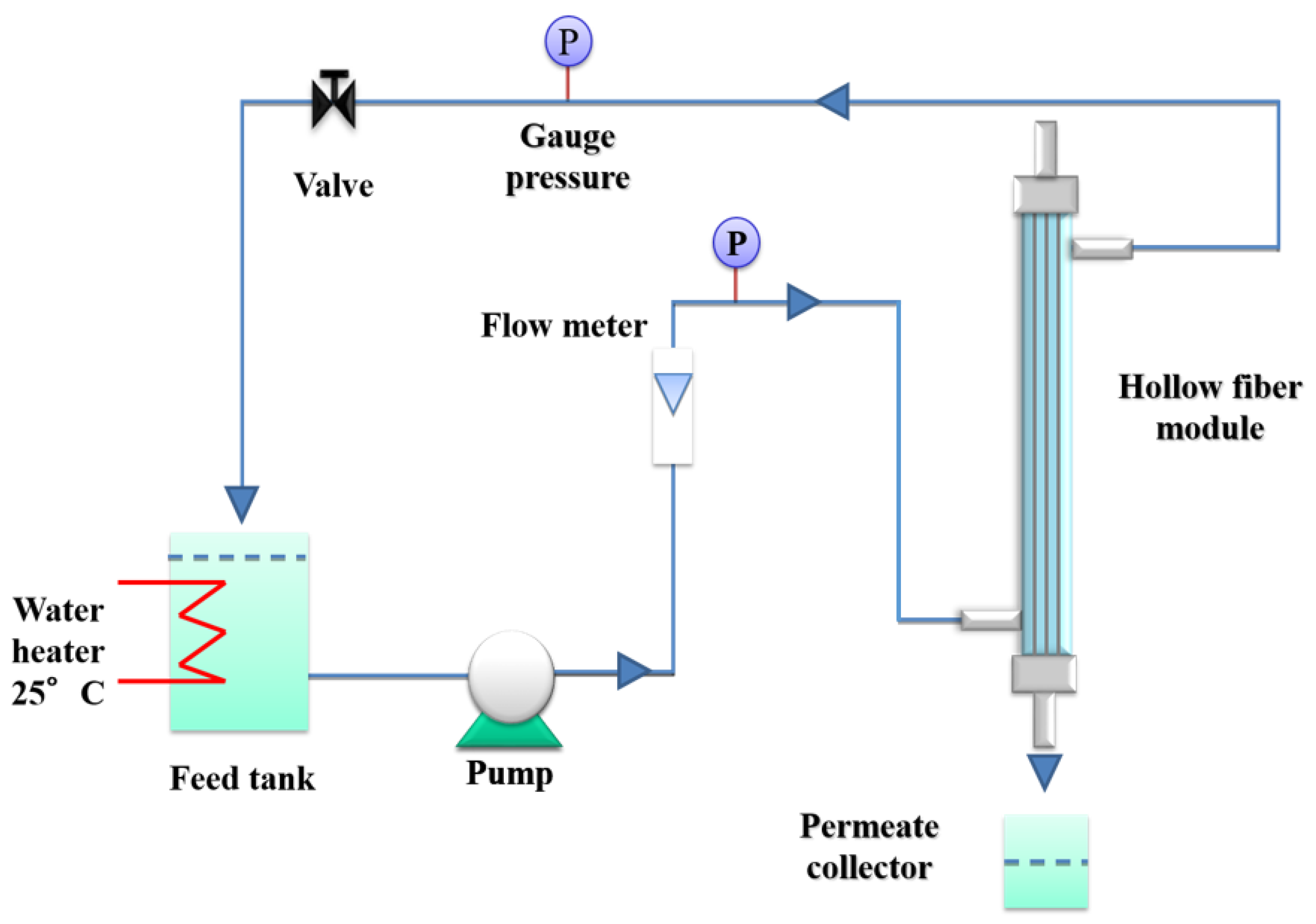
Pure water permeability (PWP) measurements were carried out in cross-flow mode with an outside-to-in configuration, using lab-made modules, each containing three hollow fibers (20 cm length). A pre-filter cartridge (pore size dimension: 20 nm) was connected between the pump and the module. The setup used for the PWP experiments is shown in Figure 1.

Figure 1.
Scheme of the setup used for the pure water permeability (PWP) measurements.
Before any PWP experiment, the modules were washed with double distilled water for glycerol removal (15 min at a transmembrane pressure (TMP) of 1.5 bar). The transmembrane water flux was calculated using the following formula:
J = Q/t·As
Where J is the flux expressed in L/m2 h, Q is the amount of permeate collected at the end of each test (L), t is the time (h), and As is the active membrane surface calculated on the basis of the fiber’s outer diameter, length, and number (m2).
J was measured three times, at three TMP values (1.5, 1.0, and 0.5 bar). The average values were calculated. The PWP (expressed in L/m2 h bar) was then calculated from the slope of the least-square fitting of the data points in a J vs. P plot.
2.6. Molecular Weight Cut-Off
The molecular weight cut-off (MWCO) was measured by using a mixture of three polydispersed dextrans with molecular weights of 11 KDa, 70 KDa, and 480 KDa. Dextrans (5 g/L in total) were dissolved in a 0.02 M buffer phosphate solution. Filtration tests were then carried out at room temperature after the water permeability tests, with an operative transmembrane pressure of 0.5 bar. The dextran solution was recirculated into the fiber module (from the shell side) and the feed and permeate were collected after about 10 min of filtration. Both samples were than analysed by gel permeation chromatography (GPC) (Accela-RI detector Thermo Scientific) (Thermo Fisher Scientific, Monza, Italy) equipped with three columns (Varian, Inc. GPC/SEC PLaquagel –OH 8 μm 300 mm × 7.5 mm, Lab Service Analytica, Anzola Emilia, Italy) connected in series and using buffer phosphate 0.02 M as the eluent phase at a flow rate of 100 μL/min. The chromatograms obtained were integrated and set with the calibration curve previously prepared with narrow dextrans. The rejection tests were carried out on the PES blank membrane (Group 4) and on the PES+TiO2 (0.3 wt %) membrane as the best representatives of the TiO2 unloaded and loaded membranes.
2.7. Stability Tests of Membranes under UV-A Irradiation
Stability tests were carried out by comparing the pure water fluxes with and without UV-A-irradiation. For the stability tests, 10 modules of each membrane hollow fiber type (with or without TiO2) were prepared and submitted to the wetting and integrity check. Each module contained three hollow fibers. Of the defect-free modules in the wetting equilibrium, five modules were kept in the dark and five modules were irradiated.
The irradiation light sources used in this study were black light PHILIPS TL-D 18W BLB 1SL with a λmax at 365 nm (lighting.philips.com). In order to irradiate multiple membrane modules simultaneously with one lamp, they were fixed in a lamp stand holding a maximum of 8 glass modules at a fixed distance of 12 cm to the UV-A lamp. In this setup, the membranes in the modules were irradiated only from one side. For this reason, they were rotated by 90° every 60 min. The UV-A intensity of 0.63 to 0.66 mW/cm2 was recorded with a YK-35UV sensor produced by Lutron Electronic behind borosilicate glass tubes and planes of the same thickness and type as the membrane modules. Internal shadowing of the membrane fibers was neglected in the evaluation.
2.8. Qualitative Methylene Blue (MB) Degradation Test
An aqueous solution of 10 μmol/L of MB (Sigma-Aldrich) was prepared and stored in the dark for 10 h. Then, the solution was put in contact with the PES+TiO2 HF located in the modules. The modules were then irradiated with a UV-A source, using the apparatus already described in the previous section, with two different exposure times: 5 h and 10 h. The MB degradation was followed in the permeate by UV-Vis spectrophotometer analyses (Hach Lange DR 3900) (Hach Lange GmbH, Berlin, Germany), using a wavelength of 664 nm. As a reference, a similar module containing PES+TiO2 HF was put in contact with the MB solution but not exposed to UV-A irradiation. Finally, a module not containing any kind of HF was filled with the MB solution and exposed to UV-A irradiation.
3. Results and Discussion
3.1. Polymeric Dope Viscosity
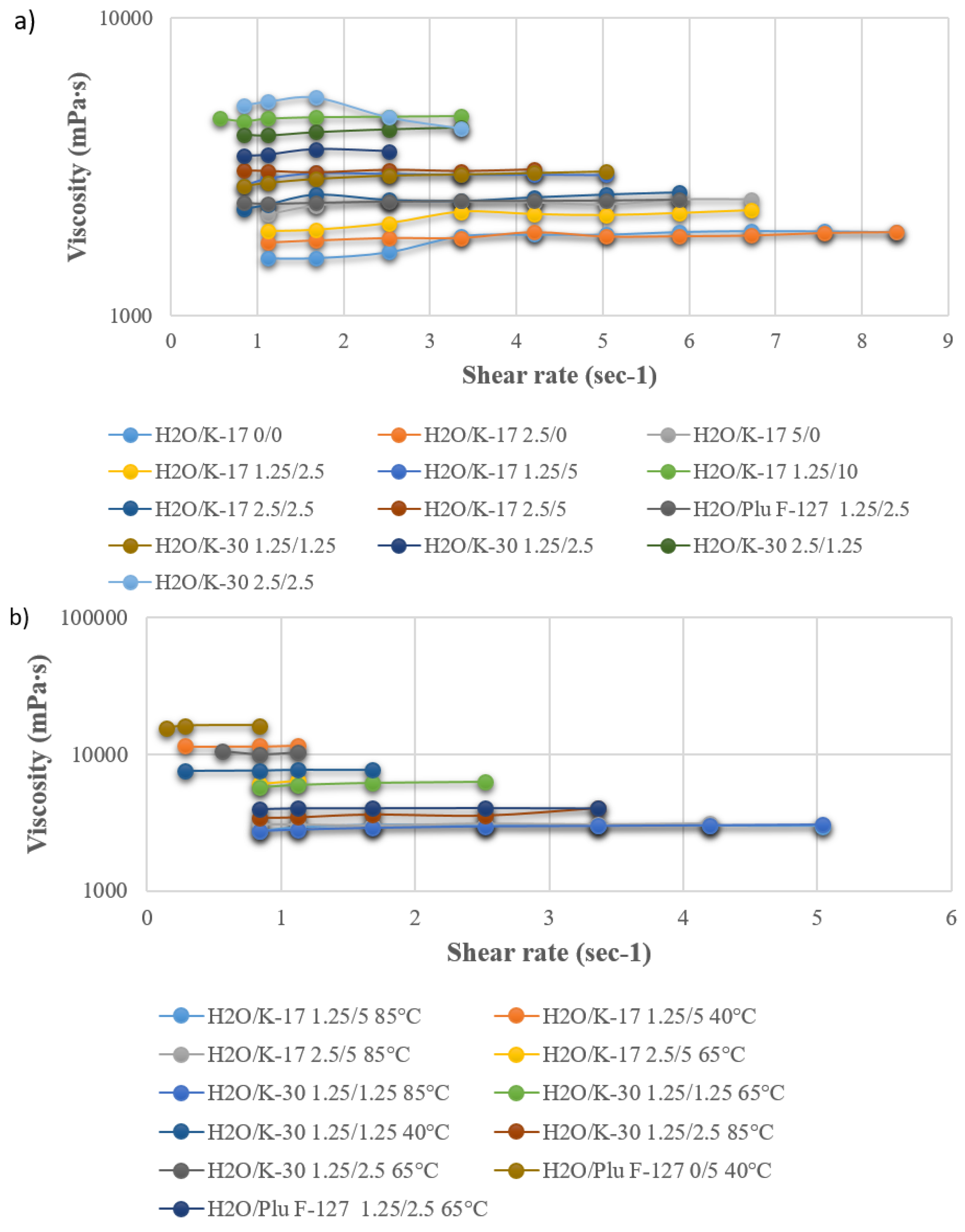
As reported in the literature [43], the viscosity is of paramount importance when spinning hollow fibers; indeed, if it is not beyond a threshold value (higher than a few thousand centipoises), their preparation is not feasible. In addition, it affects the solvent/non-solvent exchange during coagulation and, therefore, the hollow fiber final morphology [44]. In the first group of experiments, polymeric dopes were prepared while keeping constant PES and PEG 400 concentrations, in order to compare the effect of the three additives (PVP K-17, PVP K-30, and Plu F-127). A small percentage of water was also added to the dopes, since it works as an excellent pore former [20,40,41,42]. Viscosity was measured at 85 °C, since due to water’s strong non-solvent nature, demixing may take place at a lower temperature. The solution stability was then tested at lower temperatures. In the second group of experiments, the PES and PEG concentrations were fixed, and the dependence of viscosity on temperature and additive concentration was studied for selected compositions. Looking at the results (Figure 2a,b), it can be noticed that the effect of Plu F-127 on the viscosity is in between that of PVP K-17 and K-30, with all other parameters kept constant (comparing compositions containing PES/PEG400/H2O/Additive 20/30/1.25/2.5 wt %).
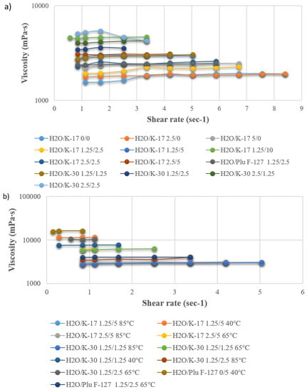
Figure 2.
(a) Viscosity of the PES dope solution as a function of additive composition at 85 °C; (b) dependence of the selected dope composition viscosity on temperature.
3.2. Blank PES Fiber Spinning Experiments and Optimization of Dope Composition
After the detailed study of dope composition, viscosity, and stability as a function of temperature, three groups of spinning experiments were carried out. All dopes contained 20% PES, while the additives were varied according to the compositions listed in Table 3 (Group 1: PEG 400/H2O/PVP K-17 30/1.25/5, Group 2: PEG 400/H2O/PVP K-17 40/1.25/5, Group 3: PEG 400/Plu F-127 30/5). In order to increase the fiber inner layer pore size, the NMP concentration in the bore fluid was increased up to 50%. However, due to the higher concentration of the solvent, the coagulation did not occur completely at the fiber inner layer. Mixtures of NMP and PEG 400 were also tested as bore fluids. In the second group of experiments, the PEG 400 concentration in the dope was increased up to 40%, strongly increasing the dope viscosity. In the last group, PLU F-127 5% was used, in combination with PEG 400 30% as the additive (without water). The produced fibers were characterized and PWP experiments were carried out.
Looking at the SEM pictures reported in Figure 3, it can be noticed that the produced fibers show similar morphologies: a thin sponge-like layer sandwiched between two thicker finger-like cavity layers. Comparing the fibers spun from the three dopes using NMP 30% as the bore fluid, it can be noticed that the sponge layer thickness is more pronounced in the fibers spun from Group 2. This increase can be explained by taking into account the delayed demixing, which is clearly connected to the dope viscosity. From Table 4, it can be seen that the viscosity of Group 2 (26,000 Cp) is higher than that of Group 1 and Group 3 (11,500 and 15,500 Cp, respectively). On the other hand, comparing the fibers produced from the same dope, but using different bore fluids (NMP 30% vs. NMP 15%/PEG 15%), it can be seen that the thickness of the sponge layer is higher in the first case (NMP 30%). This is clearly due to the low non-solvent power of the inner coagulant containing a higher solvent percentage. These results are in perfect agreement with those reported in the literature. It is widely accepted that increased dope viscosity reduces the growth of macrovoids, due to a rheological hindrance of the demixing [45]. Regarding the effect of the bore fluid composition, the addition of solvent in the coagulation media delays the solvent/non-solvent exchange, and, hence, the non-solvent influx that is responsible for void growth [46].
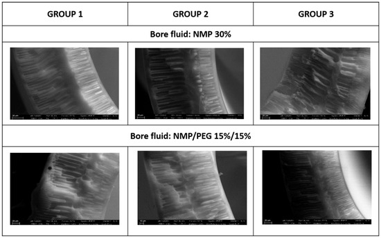
Figure 3.
Morphology of the fibers spun from experiment Groups 1–3 using two different bore fluids (NMP 30% and NMP/PEG 15%/15%).
Moreover, the NMP bore fluid concentration was, in all cases, kept far below the solvent critical concentration (CSC) responsible for a closed cell structure formation [47].
The produced fibers showed a thickness between 0.2 and 0.3 mm; porosity between 65% and 77% and a tensile modulus from 115 to 200 N/mm2. The PWP experiments showed a permeability ranging from 51 to 81 L/hm2 bar. In particular, the fibers from group 1 presented a permeability of 53–70 L/hm2 bar; fibers from group 2 presented a permeability of 51–66 L/hm2 bar; while the fibers from group 3 had a permeability of 61–81 L/hm2 bar.
From these results, it can be deduced that the higher PEG concentration was not efficient at increasing the PWP; which, instead, was improved by using Plu F-127 as the additive. Moreover, PEG/NMP 15/15% in the bore fluid increased the PWP with respect to NMP 30%.
The observed decrease of the PWP of fiber group 2 may be due to increase of the thickness of the sponge layer in the middle of the fibers, which could offer additional resistance to transport.
For the same reason, fibers produced using the NMP/PEG 15/15 mixture as the bore fluid showed higher PWP, with respect to those spun using NMP 30% as the inner coagulant, considering the same dope composition.
The increase of PWP using Plu F-127 as the additive, instead of PVP, can be also explained in line with the literature. Different studies have reported that by directly blending PES with hydrophilic polymers, such as PVP and PEG, which are also used as pore-forming agents, the hydrophilicity and the antifouling properties of membranes are all enhanced [48,49,50,51,52]. However, the elution of the blended hydrophilic polymer is unavoidable. Susanto and Ulbricht [19] compared the performance and stability of PES UF membranes using different macromolecular additives (i.e., PVP, PEG, and Pluronic). Pluronic showed the best behavior; in fact, it can be used as both a pore forming agent and to improve the hydrophilic character and, hence, the fouling resistance, of PES membranes [53]. Therefore, Pluronic was selected as the additive and, on the basis of the obtained results, another group of experiments was performed, slightly modifying the dope composition and spinning conditions.
Polymer concentration is recognized as the key parameter affecting membrane and fiber morphology and properties. Indeed, it influences both the thermodynamics and kinetics of phase inversion. A higher polymer concentration reduces the solvent volume fraction, resulting in a shift of the binodale curve towards the polymer/solvent axis [54]; as a result, less non-solvent is required to achieve phase separation. Moreover, due to its effect on viscosity, it will also affect the kinetics of the solvent/non-solvent exchange. A higher polymer concentration could result in the formation of a thicker skin layer, affecting also fiber performance, with typical trade-offs between flux and rejection. Based on these assumptions, the PES concentration was reduced from 20% to 18%. Plu F-127 5% was used as an additive; however, H2O 2% was also added to the dope, since it was found in previous works that it behaves as an excellent pore former [20,40,41,42]. Different bore fluid compositions, with PEG or PEG/NMP were also tested in this case (Group 4 in Table 3 and Table 4).
The produced fibers showed: thickness 0.2–0.3 mm; porosity 75%–78%; and tensile modulus 105–135 N/mm2. PWP measurements revealed that it increased with the increase of PEG in the bore fluid from 84 to 150 L/hm2 bar. A slight reduction of the polymer percentage (from 20 to 18 wt %) in the dope increased the PWP without affecting the fiber mechanical properties that much. From these results, the dope solution containing Plu F-127, in combination with PEG and H2O, was selected as the basis for spinning PES/TiO2 fibers. The use of PEG in the bore fluid was also successful and therefore continued.
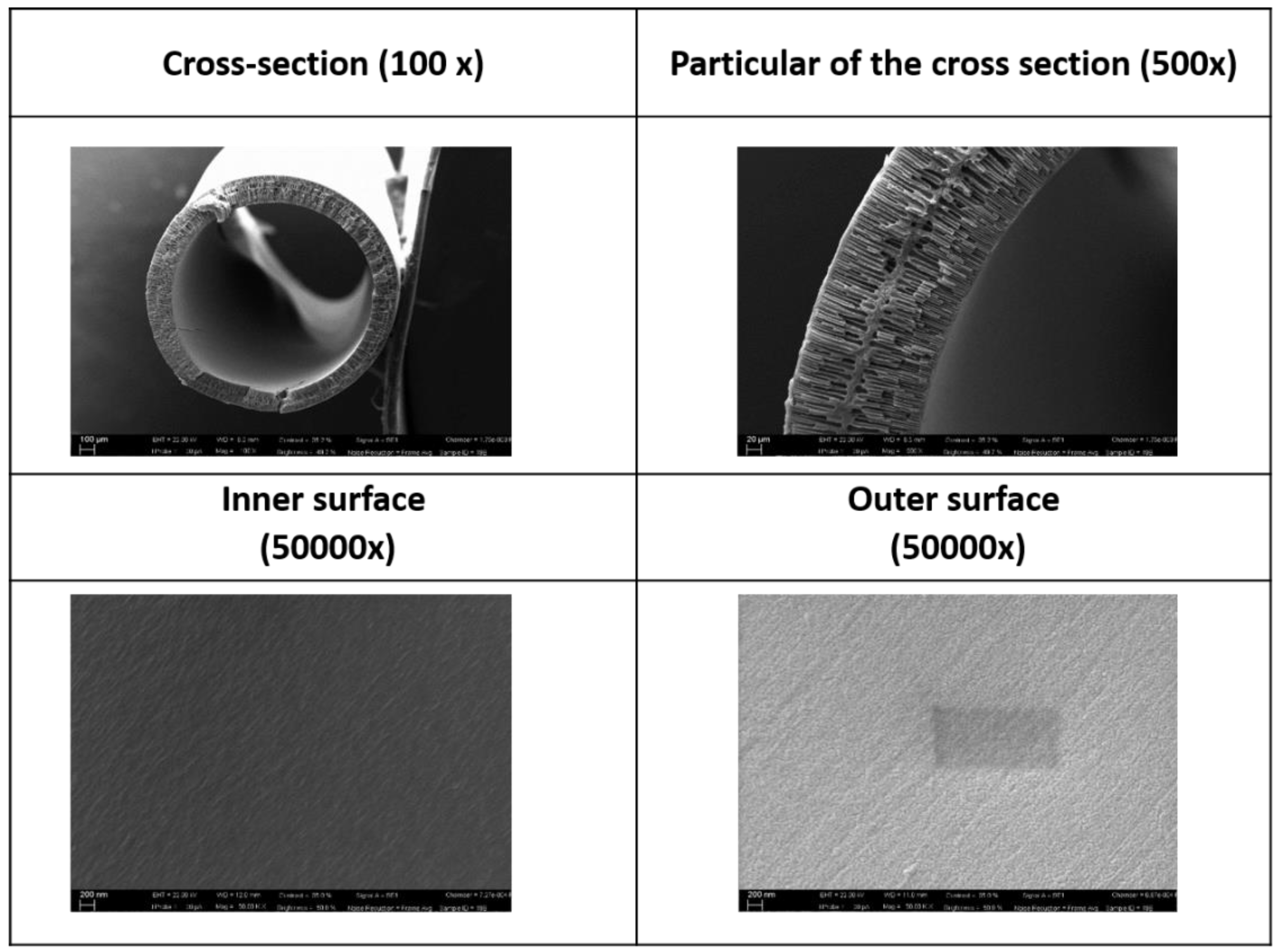
Further enhancement of fiber permeability (with respect to the 150 L/hm2 bar obtained without vapour) was achieved by increasing the humidity percentage along the air gap, by applying a suitable humidified chamber along the fiber pathway, from the spinneret to the coagulation bath. Tasselli et al. [55] observed that microdroplets in the air gap induced local phase separation at the fiber outer surface, increasing the outer surface porosity. In agreement with these findings, the PWP was further improved, and reached 185 L/hm2 bar. SEM pictures and properties of the optimized PES blank fibers are shown in Figure 4 and Table 5.
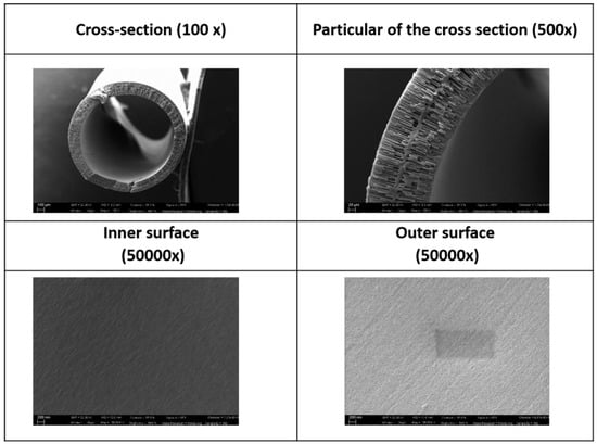
Figure 4.
SEM pictures of PES fibers with optimized dope composition (Group 4 experiments).
Table 5.
Synoptic table of the main properties of the PES fibers obtained by using the optimized composition and conditions.
3.3. Preparation and Characterization of PES-TiO2 Hollow Fibers
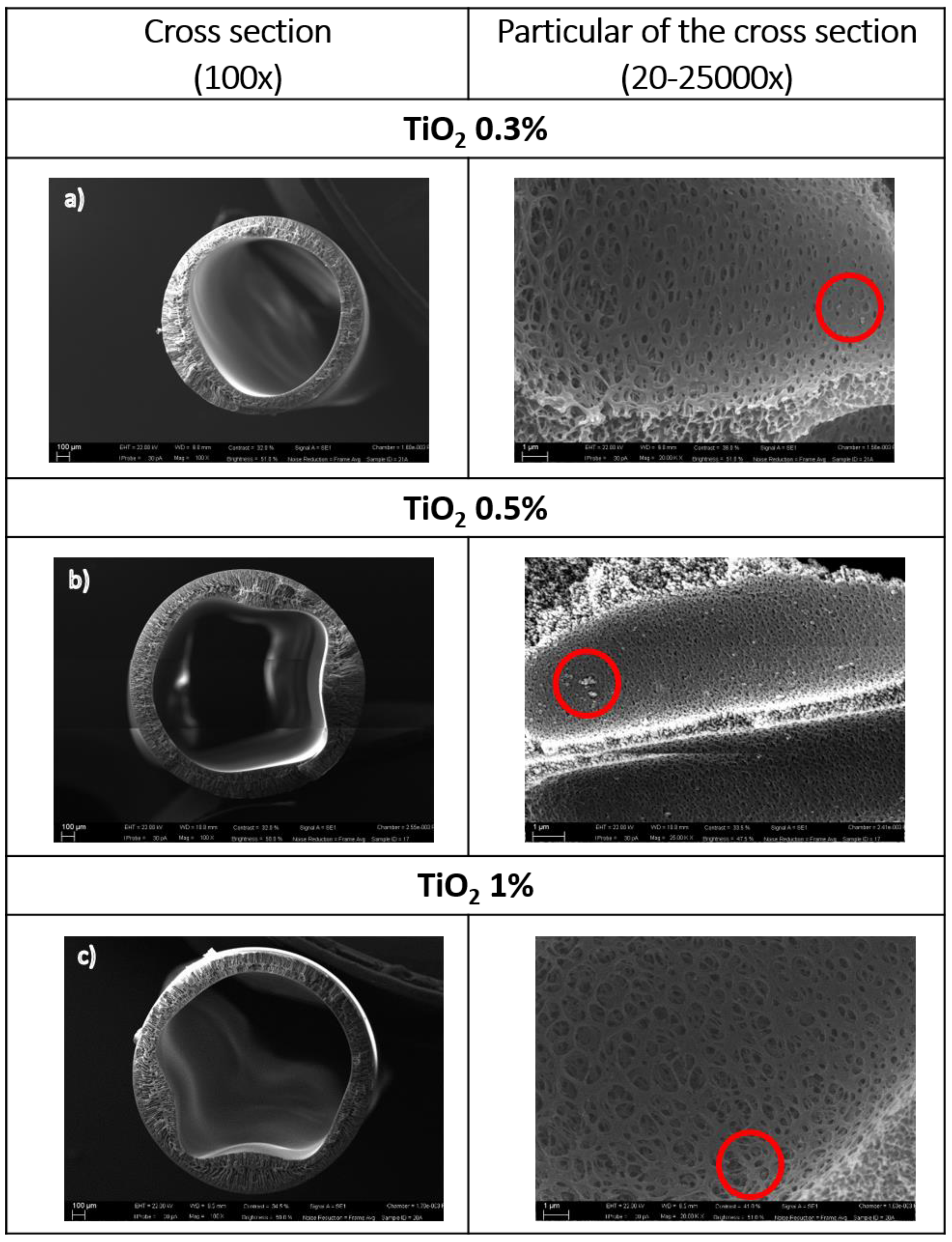
On the basis of the preliminary study, the following dope composition (PES/PEG 400/H2O/Plu F-127 18/30/2/5) was selected, and TiO2 NPs were added with a concentration ranging from 0.3 to 1 wt %. A summary of the main properties of the PES/TiO2 fibers produced (group 5 in Table 3) is reported in Table 6; SEM pictures are shown in Figure 5a–c.
Table 6.
Synoptic table of the PES-TiO2 hollow fibers produced.

Figure 5.
SEM pictures of the PES-TiO2 hollow fibers produced at different TiO2 concentrations. In the red circles, the TiO2 NPS embedded in the matrix are highlighted.
Looking at the SEM pictures reported in Figure 5, it can be noticed that the PES/TiO2 fibers prepared using a higher TiO2 concentration (0.5% and 1%) show an irregular inner contour. Such irregular morphology can be attributed to an impaired coagulation of the fiber inner surface. The excessively high concentration of TiO2 NPs in the dope may lead to the formation of aggregates, which increase the viscosity and hence hinder the solvent/non-solvent exchange process during coagulation. In order to overcome this problem, the TiO2 concentration in the dope was reduced to 0.3%, while the PEG concentration in the bore fluid was reduced from 45 to 40 wt %. This slightly increased the non-solvent power of the bore fluid and promoted a more homogeneous coagulation.
Furthermore, in the literature it was observed that when the TiO2 concentration was higher than a certain value, pure water permeability decreased significantly, probably due to pore collapse, but the overall porosity was kept constant [23].
Fibers produced with TiO2 0.3% in the dope resulted in better morphology as well as the best performance in terms of the PWP. Therefore, these fibers were selected and tested to demonstrate their photo-catalytic properties.
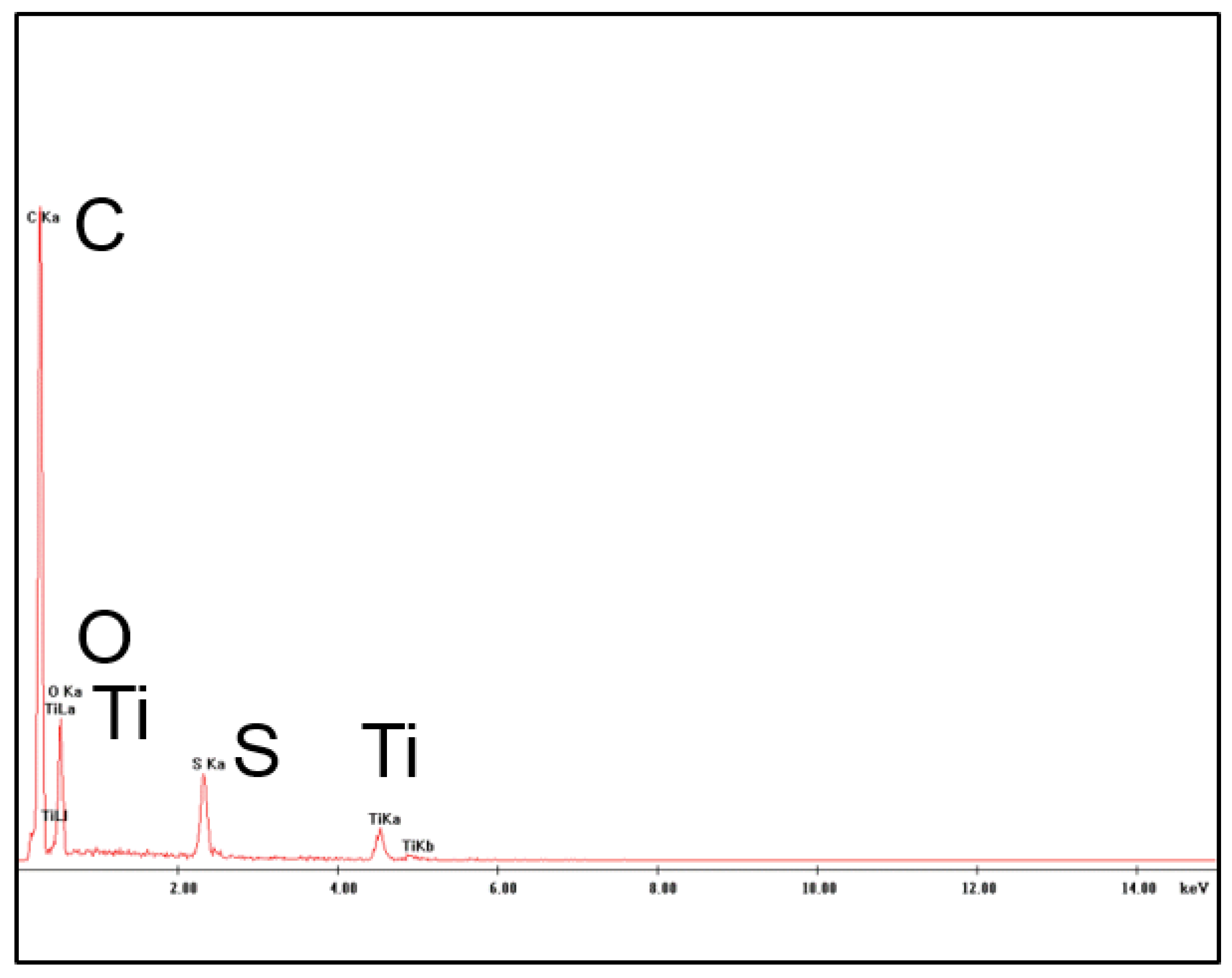
The presence of TiO2 nanoparticles in the membrane matrix was assessed through the detection of Ti and carried out by EDX measurements as shown in Figure 6.

Figure 6.
Energy Dispersive X-ray spectroscopy (EDX) analysis of the PES+TiO2 hollow fibers.
3.4. Molecular Weight Cut-off
From the cut-off results obtained, the PES membranes (Group 4) presented a cut-off of 332 KDa, placing them in the range of open UF. A decrease in the membrane cut-off (150 KDa) was observed when TiO2 (0.3 wt %) was added to the polymeric dope solution. This behavior is in line with what observed by Rahimpour et al. [56] for hybrid PVDF/SPES membranes modified with TiO2 nanoparticles. Unless the initial flux of the hybrid membranes was less than that of the neat membrane, they showed an improved rejection to bovine serum albumin (BSA) coupled with a lower flux decline. This result was explained in terms of improved resistance to fouling thanks to the photocatalytic activity and superhydrophilicity of the membranes modified with TiO2 nanoparticles.
3.5. UV-A Irradiation Stability Test Results
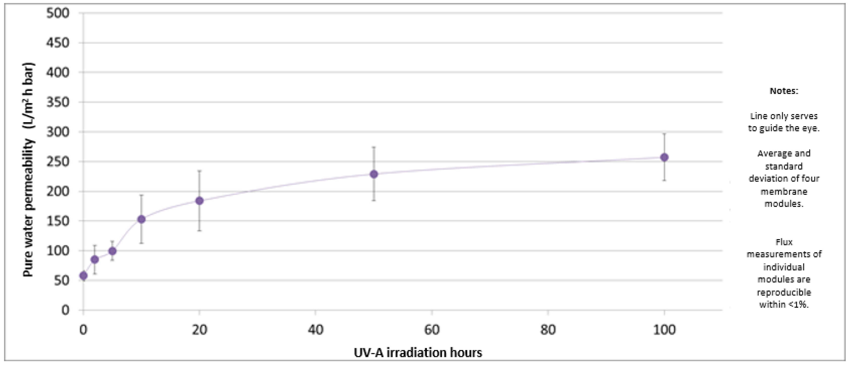
In Figure 7, the permeability values of the PES-TiO2 hollow fiber membranes under UV irradiation are reported.
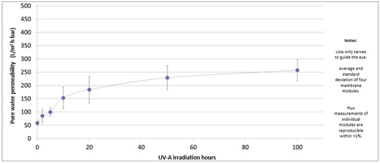
Figure 7.
Permeability values of the PES-TiO2 hollow fiber membranes as a function of UV irradiation time.
The permeability value increases very fast in the first 10 h, after which it reaches a constant value. This may be caused by a degradation of the membrane selective layer due to the photocatalytic reaction. On the other hand, experiments performed under the same conditions but without UV irradiation showed that the PWP for PES-TiO2 hollow fiber membranes was stable at around 75 L/m2 h bar, with no significant variation over time.
It was deduced that the increased permeability is due to photo-degradation of the membrane selective layer by the combination of UV-A light and the TiO2 catalyst, because a set of reference PES hollow fiber membranes did not show a permeability increase under the same irradiation conditions (data not shown). This is an indication that the PES-TiO2 ultrafiltration membranes are not stable in UV-A irradiation of 0.6 mW/cm2. However, the produced hollow fibers could be suitable for other applications, e.g., non-irradiated ultrafiltration or membrane reactor applications (microfiltration with irradiation), thanks to the antimicrobial and anti-fouling properties of the TiO2 nanoparticles [57,58].
3.6. Qualitative Methylene Blue (MB) Degradation Test
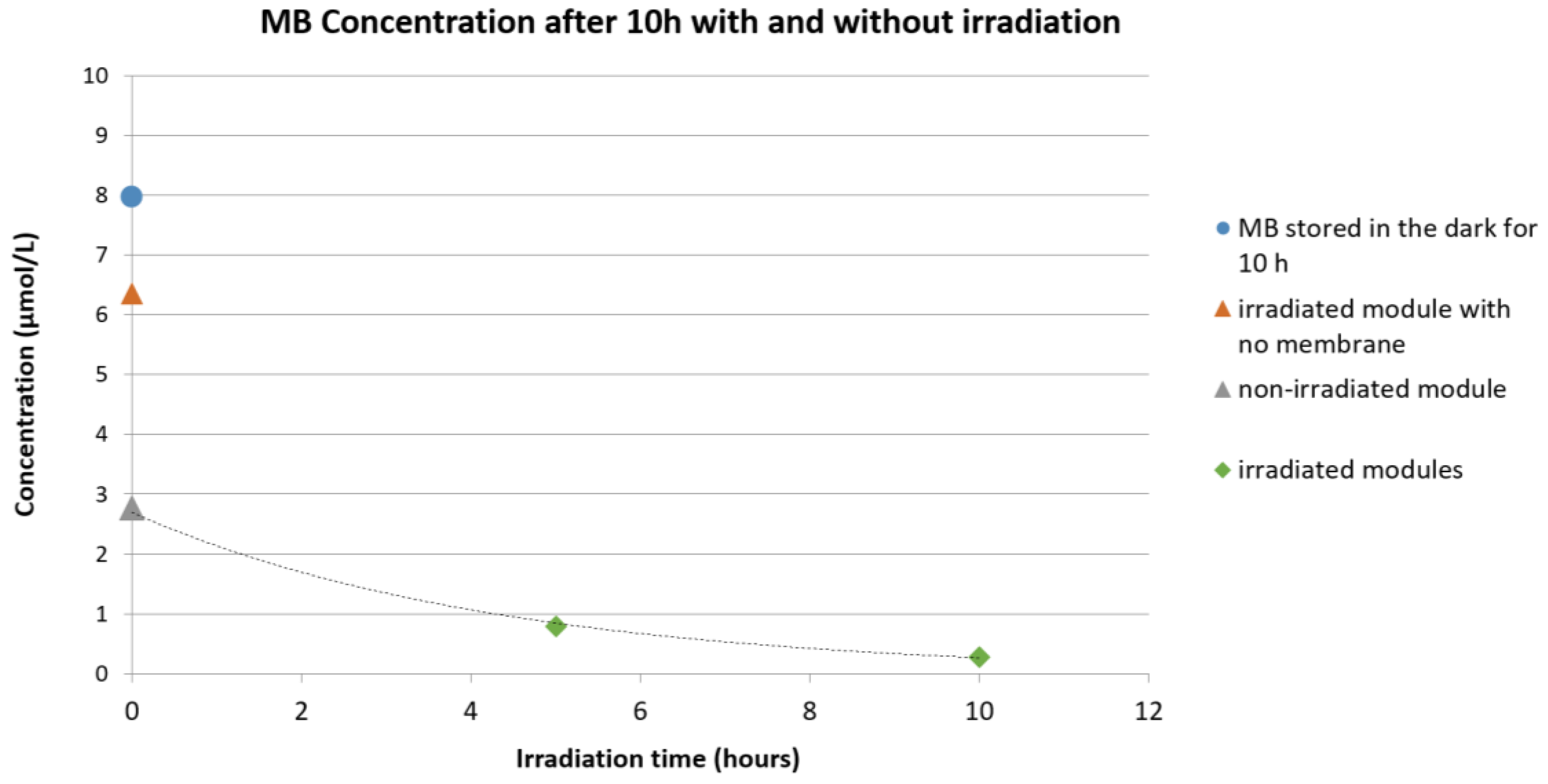
In Figure 8, the qualitative degradation of MB exposed under UV-A at different conditions is reported. As can be observed, when a module filled with the MB aqueous solution but not containing any fiber was exposed to UV-A irradiation, a small decrease in the absorbance was seen and can be related to a partial spontaneous degradation of the dye. A clear decrease of MB concentration, however, could be observed when the MB aqueous solution was put directly in contact with the PES+TiO2 hollow fibers. A large part of this is due to the adsorption of MB on and into the membrane hollow fibers. However, the comparison of three modules (with and without UV-A irradiation) after the same adsorption time demonstrates the catalytic activity of the PES-TiO2 hollow fiber membranes.
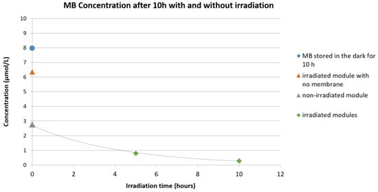
Figure 8.
Qualitative concentration change of the aqueous methylene blue (MB) solution: Blue circle: MB solution stored in the dark for 10 h; orange triangle: irradiated module filled with MB solution but not containing any fiber; grey triangle: non-irradiated module containing PES+TiO2 hollow fibers (HF); green diamond: irradiated module containing PES+TiO2 HF.
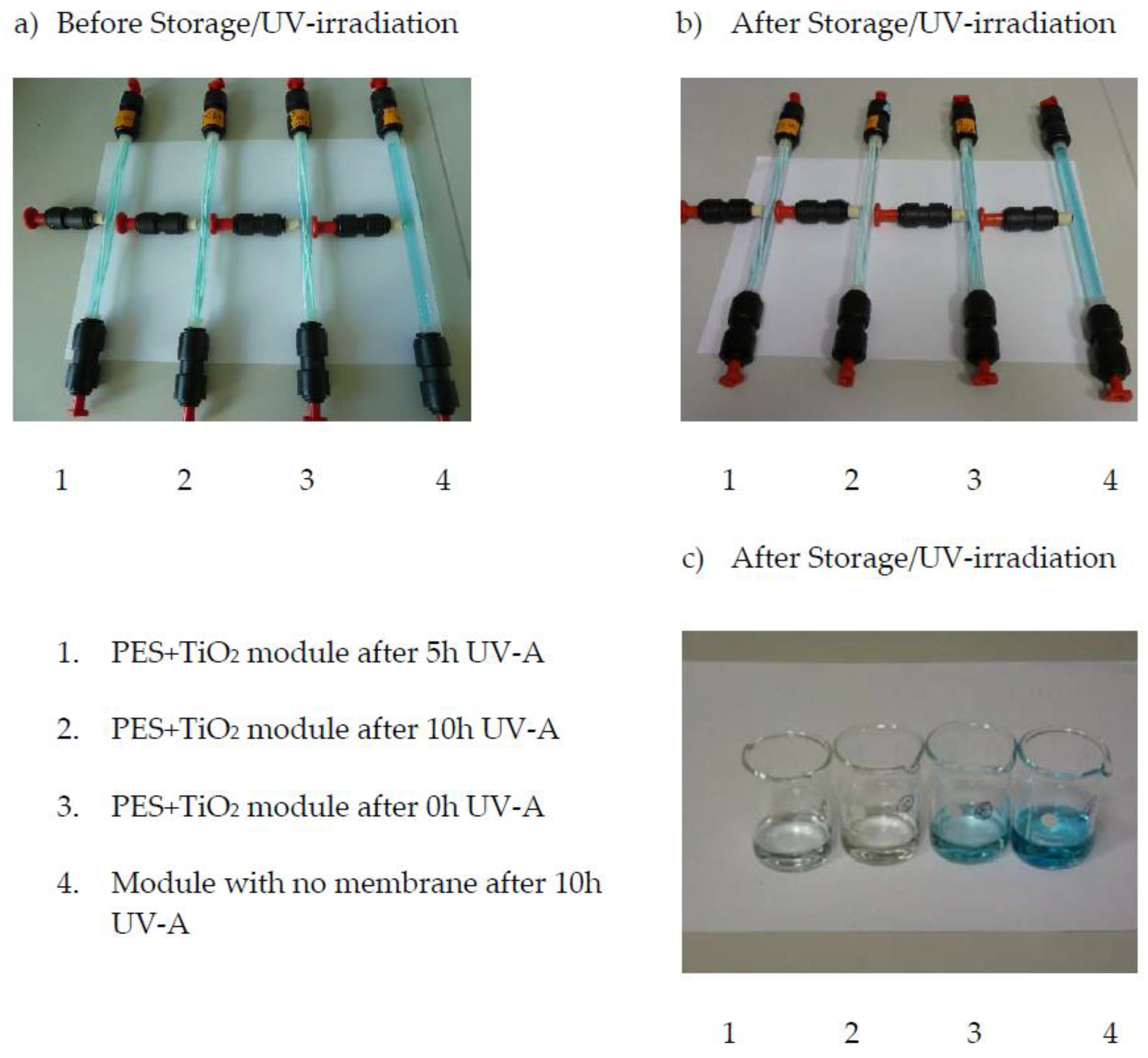
Figure 9 shows the membrane modules 1, 2, and 4 before (a) and after (b) UV-A irradiation. Module number 3 was not exposed to UV-A light and is added for comparison. The color of the solutions drained from these modules can be compared in Figure 9c. (The corresponding absorbance is given in Figure 8). The photo-catalytic activity of the TiO2 nanoparticles contained in the PES membranes was in fact allowed to almost totally degrade the MB.
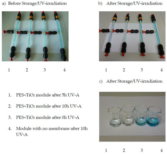
Figure 9.
Qualitative concentration change of the aqueous methylene blue solution: (a) Images of modules before storage or UV-A irradiation; (b) Images of modules after storage or UV-A irradiation; (c) Image of the solutions drained from these modules after storage or UV-A irradiation.
5. Conclusions
PES-TiO2 hollow fiber membranes for applications in water treatment were prepared, using a combination of water and Pluronic® F-127 as additives. The effect of different additive composition and temperature on dope viscosity and stability was investigated. Different spinning experiments of “blank” PES fibers were performed, in order to identify the best dope composition. After obtaining PES fibers with optimized properties, TiO2 NPs, with concentrations ranging from 0.3 to 1 wt %, were introduced in the dope composition and the PES/TiO2 fibers were produced.
The main conclusions of the present research work are as follows:
- Fiber morphology and, in particular, the growth of finger-like macrovoids vs. sponge like morphology, are clearly affected by the dope viscosity and bore fluid composition.
- Fiber properties are dependent on the morphology, with fibers having a thicker sponge-like layer showing reduced PWP.
- Slight reduction of the polymer concentration, the combination of Pluronic® and water as additives, and the use of PEG 400 in the bore fluid resulted in the fibers with best properties.
- Increase of the humidity percentage in the air gap further improved the fiber permeability.
- High NP concentrations in the dope impaired fiber coagulation, giving rise to irregular morphologies.
- An NP concentration of 0.3 wt % gave the best results in terms of fiber morphology and properties.
The photocatalytic properties of the prepared hollow fibers were tested. The PES HF fibers loaded with TiO2 particles were demonstrated to be photoactive in the degradation of MB. However, their selective layer was damaged during UV-A irradiation of only 2 h at 0.6 mW/cm2. This indicates that the PES-TiO2 ultrafiltration membranes are not resistant under UV light. Nevertheless, the detailed investigation, carried out on the dope composition and spinning conditions, can be useful as a starting point for further investigations on PES hollow fiber membrane preparation.
Acknowledgments
The authors gratefully acknowledge financial support from the European Union’s Seventh Framework Programme (FP7/2007–2013), and the NAWADES project (Nanotechnological Application in Water DESalination), grant agreement No. 308439.
Author Contributions
Silvia Simone, Alberto Figoli and Enrico Drioli conceived, designed the experiments and wrote the article; Silvia Simone, Francesco Galiano and Alberto Figoli prepared and characterized the hollow fiber membranes; Mirko Faccini and Marcel E. Boerrigter prepared the TiO2 dispersion used in the dope solution; Christiane Chaumette supervised and analysed the UV-A Irradiation Stability Tests and the qualitative Methylene Blue (MB) Degradation Test. She contributed text sections of this paper.
Conflicts of Interest
The authors declare no conflict of interest.
References
- Shannon, M.A.; Bohn, P.W.; Elimelech, M.; Georgiadis, J.G.; Marinas, B.J.; Mayes, A.M. Science and technology for water purification in the coming decades. Nature 2008, 452, 301–310. [Google Scholar] [CrossRef] [PubMed]
- Drioli, E.; Stankiewicz, A.I.; Macedonio, F. Membrane engineering in process intensification—An overview. J. Membr. Sci. 2011, 380, 1–8. [Google Scholar] [CrossRef]
- Drioli, E.; Macedonio, F. Membrane engineering for water engineering. Ind. Eng. Chem. Res. 2012, 51, 10051–10056. [Google Scholar] [CrossRef]
- Flemming, H.C.; Schaule, G.; Griebe, T.; Schmitt, J.; Tamachkiarowa, A. Biofouling—The Achilles heel of membrane processes. Desalination 1997, 113, 215–225. [Google Scholar] [CrossRef]
- Jhaveri, J.H.; Murthy, Z.V.P. A comprehensive review on anti-fouling nanocomposite membranes for pressure driven membrane separation processes. Desalination 2016, 379, 137–154. [Google Scholar] [CrossRef]
- Ng, L.Y.; Mohammad, A.W.; Leo, C.P.; Hilal, N. Polymeric membranes incorporated with metal/metal oxide nanoparticles: A comprehensive review. Desalination 2013, 308, 15–33. [Google Scholar] [CrossRef]
- Shen, Y.; Lua, A.C. Preparation and characterization of mixed matrix membranes based on PVDF and three inorganic fillers (fumed nonporous silica, zeolite 4A and mesoporous MCM-41) for gas separation. Chem. Eng. J. 2012, 192, 201–210. [Google Scholar] [CrossRef]
- Anadao, P.; Sato, L.F.; Wiebeck, H.; Valenzuela-Diaz, F.R. Montmorillonite as a component of polysulfone nanocomposite membranes. Appl. Clay. Sci. 2010, 48, 127–132. [Google Scholar] [CrossRef]
- Wang, Z.; Yu, H.; Xia, J.; Zhang, F.; Li, F.; Xia, Y.; Li, Y. Novel GO-blended PVDF ultrafiltration membranes. Desalination 2012, 299, 50–54. [Google Scholar] [CrossRef]
- Zhao, Y.; Xu, Z.; Shan, M.; Min, C.; Zhou, B.; Li, Y.; Li, B.; Liu, L.; Qian, X. Effect of graphite oxide and multi-walled carbon nanotubes on the microstructure and performance of PVDF membranes. Sep. Purif. Technol. 2013, 103, 78–83. [Google Scholar] [CrossRef]
- Kou, L.; Gao, C. Making silica nanoparticle-covered graphene oxide nanohybrids as general building blocks for large-area superhydrophilic coatings. Nanoscale 2011, 3, 519–528. [Google Scholar] [CrossRef] [PubMed]
- Zhang, H.; Lv, X.; Li, Y.; Wang, Y.; Li, J. P25-graphene composite as a high performance photocatalyst. ACS Nano 2009, 4, 380–386. [Google Scholar] [CrossRef] [PubMed]
- Safarpour, M.; Vatanpour, V.; Khataee, A. Preparation and characterization of graphene oxide/TiO2 blended PES nanofiltration membrane with improved antifouling and separation performance. Desalination 2016, 393, 65–78. [Google Scholar] [CrossRef]
- Bet-Moushoul, E.; Mansourpanah, Y.; Farhadi, K.; Tabatabaei, M. TiO2 nanocomposite based polymeric membranes: A review on performance improvement for various applications in chemical engineering processes. Chem. Eng. J. 2016, 283, 29–46. [Google Scholar] [CrossRef]
- Madaeni, S.S.; Rahimpour, A. Effect of type of solvent and non-solvents on morphology and performance of polysulfone and polyethersulfone ultrafiltration membranes for milk concentration. Polym. Adv. Technol. 2005, 16, 717–724. [Google Scholar] [CrossRef]
- Idris, A.; Zain, N.M.; Noordin, M.Y. Synthesis, characterization and performance of asymmetric polyethersulfone (PES) ultrafiltration membranes with polyethylene glycol of different molecular weights as additives. Desalination 2007, 207, 324–339. [Google Scholar] [CrossRef]
- Li, J.F.; Xu, Z.L.; Yang, H. Microporous polyethersulfone membranes prepared under the combined precipitation conditions with non-solvent additives. Polym. Adv. Technol. 2008, 19, 251–257. [Google Scholar] [CrossRef]
- Susanto, H.; Stahra, N.; Ulbricht, M. High performance polyethersulfone microfiltration membranes having high flux and stable hydrophilic property. J. Membr. Sci. 2009, 342, 153–164. [Google Scholar] [CrossRef]
- Susanto, H.; Ulbricht, M. Characteristics, performance and stability of polyethersulfone ultrafiltration membranes prepared by phase separation method using different macromolecular additives. J. Membr. Sci. 2009, 327, 125–135. [Google Scholar] [CrossRef]
- Alsalhy, Q.F.; Salih, H.A.; Simone, S.; Zablouk, M.; Drioli, E.; Figoli, A. Poly (ether sulfone) (PES) hollow-fiber membranes prepared from various spinning parameters. Desalination 2014, 345, 21–35. [Google Scholar] [CrossRef]
- Li, J.F.; Xu, Z.L.; Yang, H.; Yu, L.Y.; Liu, M. Effect of TiO2 nanoparticles on the surface morphology and performance of microporous PES membrane. Appl. Surf. Sci. 2009, 255, 4725–4732. [Google Scholar] [CrossRef]
- Razmjou, A.; Mansouri, J.; Chen, V. The effect of mechanical and chemical modification of TiO2 nanoparticles on the surface chemistry, structure and fouling performance of PES ultrafiltration membranes. J. Membr. Sci. 2011, 378, 73–84. [Google Scholar] [CrossRef]
- Wu, G.P.; Gan, S.Y.; Cui, L.Z.; Xu, Y.Y. Preparation and characterization of PES/TiO2 composite membranes. Appl. Surf. Sci. 2008, 254, 7080–7086. [Google Scholar] [CrossRef]
- Vatanpour, V.; Madaeni, S.S.; Khataee, A.R.; Salehi, E.; Zinadini, S.; Monfared, H.A. TiO2 embedded mixed matrix PES nanocomposite membranes: Influence of different sizes and types of nanoparticles on antifouling and performance. Desalination 2012, 292, 19–29. [Google Scholar] [CrossRef]
- Razmjou, A.; Resosudarmo, A.; Holmes, R.L.; Li, H.; Mansouri, J.; Chen, V. The effect of modified TiO2 nanoparticles on the polyethersulfone ultrafiltration hollow fiber membranes. Desalination 2012, 287, 271–280. [Google Scholar] [CrossRef]
- Liang, C.-Y.; Uchytil, P.; Petrychkovych, R.; Lai, Y.-C.; Friess, K.; Sipek, M.; Reddy, M.M.; Suen, S.-Y. A comparison on gas separation between PES (polyethersulfone)/MMT (Na-montmorillonite) and PES/TiO2 mixed matrix membranes. Sep. Purif. Technol. 2012, 92, 57–63. [Google Scholar] [CrossRef]
- Mansourpanah, Y.; Madaeni, S.S.; Rahimpour, A. Formation of appropriate sites on nanofiltration membrane surface for binding TiO2 photo-catalyst: Performance, characterization and fouling resistant capability. J. Membr. Sci. 2009, 330, 297–306. [Google Scholar] [CrossRef]
- Rahimpour, A.; Madaeni, S.S.; Taheri, A.H.; Mansourpanah, Y. Coupling TiO2 nanoparticles with UV irradiation for modification of polyethersulfone ultrafiltration membranes. J. Membr. Sci. 2008, 313, 158–169. [Google Scholar] [CrossRef]
- Razmjou, A.; Mansouri, J.; Chen, V.; Lim, M.; Amal, R. Titania nanocomposite polyethersulfone ultrafiltration membranes fabricated using a low temperature hydrothermal coating process. J. Membr. Sci. 2011, 380, 98–113. [Google Scholar] [CrossRef]
- Luo, M.-L.; Zhao, J.-Q.; Tang, W.; Pu, C.-S. Hydrophilic modification of poly(ether sulfone) ultrafiltration membrane surface by self-assembly of TiO2 nanoparticles. Appl. Surf. Sci. 2005, 249, 76–84. [Google Scholar] [CrossRef]
- Pourjafar, S.; Rahimpour, A.; Jahanshahi, M. Synthesis and characterization of PVA/PES thin film composite nanofiltration membrane modified with TiO2 nanoparticles for better performance and surface properties. J. Ind. Eng. Chem. 2012, 18, 1398–1405. [Google Scholar] [CrossRef]
- Chung, T.S.; Qin, J.J.; Gu, J. Effect of shear rate within the spinneret on morphology, separation performance and mechanical properties of ultrafiltration polyethersulfone hollow fiber membranes. Chem. Eng. Sci. 2000, 55, 1077–1091. [Google Scholar] [CrossRef]
- Yuliwati, E.; Ismail, A.F.; Matsuura, T.; Kassim, M.A.; Abdullah, M.S. Effect of modified PVDF hollow fiber submerged ultrafiltration membrane for refinery wastewater treatment. Desalination 2011, 283, 214–220. [Google Scholar] [CrossRef]
- Han, L.F.; Xu, Z.L.; Yu, L.Y.; Wei, Y.M.; Cao, Y. Performance of PVDF/Multi-nanoparticles composite hollow fibre ultrafiltration membranes. Iran. Polym. J. (Engl. Ed.) 2010, 19, 553–565. [Google Scholar]
- Chiang, C.Y.; Jaipal Reddy, M.; Chu, P.P. Nano-tube TiO2 composite PVDF/LiPF6 solid membranes. Solid State Ionics 2004, 175, 631–635. [Google Scholar] [CrossRef]
- Yu, L.-Y.; Shen, H.-M.; Xu, Z.-L. PVDF–TiO2 composite hollow fiber ultrafiltration membranes prepared by TiO2 sol–gel method and blending method. J. Appl. Polym. Sci. 2009, 113, 1763–1772. [Google Scholar] [CrossRef]
- Dzinun, H.; Othman, M.H.D.; Ismail, A.F.; Puteh, M.H. Photocatalytic degradation of nonylphenol by immobilized TiO2 in dual layer hollow fibre membranes. Chem. Eng. J. 2015, 269, 255–261. [Google Scholar] [CrossRef]
- Dzinun, H.; Othman, M.H.D.; Ismail, A.F.; Puteh, M.H.; Rahman, M.A.; Jaafar, J. Stability study of PVDF/TiO2 dual layer hollow fibre membranes under long-term UV irradiation exposure. J. Water Process Eng. 2016, in press. [Google Scholar] [CrossRef]
- Zhang, Q.; Wang, H.; Fan, X.; Chen, S.; Yu, H.; Quan, X. A controlled wet-spinning and dip-coating process for preparation of high-permeable TiO2 hollow fiber membranes. Water Sci. Technol. 2016, 73, 725–733. [Google Scholar] [PubMed]
- Figoli, A.; Simone, S.; Criscuoli, A.; Al-Jlil, S.A.; Al Shabouna, F.S.; Al-Romaih, H.S.; Di Nicolò, E.; Al-Harbi, O.A.; Drioli, E. Hollow fibers for seawater desalination from blends of PVDF with different molecular weights: Morphology, properties and VMD performance. Polymer 2014, 55, 1296–1306. [Google Scholar] [CrossRef]
- Simone, S.; Figoli, A.; Criscuoli, A.; Carnevale, M.C.; Alfadul, S.; Al-Romaih, H.; Al Shabouna, F.; Al-Harbi, O.A.; Drioli, E. Effect of selected spinning parameters on PVDF hollow fibers morphology for potential application in desalination by VMD. Desalination 2014, 344, 28–35. [Google Scholar] [CrossRef]
- Simone, S.; Figoli, A.; Criscuoli, A.; Carnevale, M.C.; Rosselli, A.; Drioli, E. Preparation of hollow fibre membranes from PVDF/PVP blends and their application in VMD. J. Membr. Sci. 2010, 364, 219–232. [Google Scholar] [CrossRef]
- Wang, D. Polyethersulfone Hollow Fiber Gas Separation Membranes Prepared from Solvent Systems Containing Nonsolvent-Additives. Ph.D. Thesis, Department of Chemical Engineering, National University of Singapore, Singapore, 1995. [Google Scholar]
- Li, Q.; Xu, Z.L.; Yu, L.-Y. Effects of mixed solvents and PVDF types on performances of PVDF microporous membranes. J. Appl. Polym. Sci. 2010, 115, 2277–2287. [Google Scholar] [CrossRef]
- Lee, K.-W.; Se, B.-K.; Nam, S.-T.; Han, M.-J. Trade-off between thermodynamic enhancement and kinetic hindrance during phase inversion in the preparation of polysulfone membranes. Desalination 2003, 159, 289–296. [Google Scholar] [CrossRef]
- Guillen, G.R.; Ramon, G.Z.; Pirouz Kavehpour, H.; Kaner, R.B.; Hoek, E.M.V. Direct microscopic observation of membrane formation by nonsolvent induced phase separation. J. Membr. Sci. 2013, 431, 212–220. [Google Scholar] [CrossRef]
- Li, X.-M.; He, T. Does more solvent in bore liquid create more open inner surface in hollow fiber membranes? Polym. Adv. Technol. 2008, 19, 801–806. [Google Scholar] [CrossRef]
- Wang, H.T.; Yu, T.; Zhao, C.Y.; Du, Q.Y. Improvement of hydrophilicity and blood compatibility on polyethersulfone membrane by adding polyvinylpyrrolidone. Fiber Polym. 2009, 10, 1–5. [Google Scholar] [CrossRef]
- Wang, Y.Q.; Wang, T.; Su, Y.L.; Peng, F.B.; Wu, H.; Jiang, Z.Y. Protein-adsorption-resistance and permeation property of polyethersulfone and soybean phosphatidylcholine blend ultrafiltration membranes. J. Membr. Sci. 2006, 270, 108–114. [Google Scholar] [CrossRef]
- Barzin, J.; Feng, C.; Khulbe, K.C.; Matsuura, T.; Madaeni, S.S.; Mirzadeh, H. Characterization of polyethersulfone hemodialysis membrane by ultrafiltration and atomic force microscopy. J. Membr. Sci. 2004, 237, 77–85. [Google Scholar] [CrossRef]
- Mosqueda-Jimenez, D.B.; Narbaitz, R.M.; Matsuura, T. Effects of preparation conditions on the surface modification and performance of polyethersulfone ultrafiltration membranes. J. Appl. Polym. Sci. 2006, 99, 2978–2988. [Google Scholar] [CrossRef]
- Su, B.H.; Fu, P.; Li, Q.; Tao, Y.; Li, Z.; Zhao, C.S. Evaluation of polyethersulfone high flux hemodialysis membrane in vitro and in vivo. J. Mater. Sci. Mater. Med. 2008, 19, 745–751. [Google Scholar] [CrossRef] [PubMed]
- Zhao, W.; Su, Y.L.; Li, C.; Shi, Q.; Ning, X.; Jiang, Z.Y. Fabrication of antifouling polyethersulfone ultrafiltration membranes using Pluronic F127 as both surface modifier and pore-forming agent. J. Membr. Sci. 2008, 318, 405–412. [Google Scholar] [CrossRef]
- Tasselli, F.; Jansen, J.C.; Drioli, E. PEEKWC Ultrafiltration Hollow-Fiber Membranes: Preparation, Morphology, and Transport Properties. J. Appl. Polym. Sci. 2004, 91, 841–853. [Google Scholar] [CrossRef]
- Tasselli, F.; Jansen, J.C.; Sidari, F.; Drioli, E. Morphology and transport property control of modified poly(ether ether ketone) (PEEKWC) hollow fiber membranes prepared from PEEKWC/PVP blends: Influence of the relative humidity in the air gap. J. Membr. Sci. 2005, 255, 13–22. [Google Scholar] [CrossRef]
- Rahimpour, A.; Jahanshahi, M.; Mollahosseini, A.; Rajaeian, B. Structural and performance properties of UV-assisted TiO2 deposited nano-composite PVDF/SPES membranes. Desalination 2012, 285, 31–38. [Google Scholar] [CrossRef]
- Hu, W.; Yin, J.; Deng, B.; Hu, Z. Application of nano TiO2 modified hollow fiber membranes in algal membrane bioreactors for high-density algae cultivation and wastewater polishing. Bioresour. Technol. 2015, 193, 135–141. [Google Scholar] [CrossRef] [PubMed]
- Emadzadeh, D.; Lau, W.J.; Matsuura, T.; Ismail, A.F.; Rahbari-Sisakht, M. Synthesis and characterization of thin film nanocomposite forward osmosis membrane with hydrophilic nanocomposite support to reduce internal concentration polarization. J. Membr. Sci. 2014, 449, 74–85. [Google Scholar] [CrossRef]

© 2017 by the authors. Licensee MDPI, Basel, Switzerland. This article is an open access article distributed under the terms and conditions of the Creative Commons Attribution (CC BY) license (http://creativecommons.org/licenses/by/4.0/).