Article

Method for Developing the System Architecture of Existing Industrial Objects for Digital Representation Tasks

Manufacturing Processes Simulation and Power Equipment Design Laboratory, World-Class Research Center for Advanced Digital Technologies, Peter the Great St. Petersburg Polytechnic University, St. Petersburg 195251, Russia
*
Author to whom correspondence should be addressed.
Systems 2024, 12(9), 355; https://doi.org/10.3390/systems12090355
Submission received: 25 July 2024 / Revised: 2 September 2024 / Accepted: 4 September 2024 / Published: 9 September 2024
(This article belongs to the Special Issue Advanced Model-Based Systems Engineering)

Abstract

:
This paper presents a method for creating the system architecture of existing industrial objects based on Model-Based Systems Engineering (MBSE) principles. The method aims to form a digital representation of physical objects, which is crucial in the digital transformation of industrial enterprises. It allows for the accurate reflection of all components, processes, functions, and interrelationships within an object. The methodology includes stages of data collection, structuring, development of ontological models, and the integration of a comprehensive system architecture into the digital space. This method was tested using a small hydroelectric power plant, revealing its key advantages and disadvantages and identifying areas for further improvement. The main findings indicate a significant improvement in understanding the system architecture for scenario modeling and digital operation of the objects. Despite challenges such as the need for multiple iterations and high data requirements, the methodology demonstrates the potential for applying MBSE in the digital transformation of existing industrial objects.

1. Introduction

Digital transformation and, in particular, digital engineering are essential attributes of modern enterprises. Digital engineering (DE) applied to an existing industrial object involves the creation of a digital representation of a physical-world object in the virtual world [1]. The complexity of this task lies in the significant number of constraints, including the need to ensure that the digital representation of all components and the system architecture of the object match the real-world object, i.e., its adequacy (Figure 1).
Developing system architecture, models, and corresponding analytics and calculations are key factors in maintaining the adequacy of the digital object to its physical counterpart [2,3]. For new industrial facilities, these procedures are conducted during the design phase [4]. Subsequently, during construction and installation, methodologies such as “As-is and as-built” (specific methodologies for building information modeling) ensure that the physical object corresponds to its digital representation in the virtual world [5]. To support modernization, reconstruction, operational process changes, analysis, or other objectives, it is also necessary to create digital representations of existing industrial facilities [6]. By ‘industrial facility’ here, we mean a complex technical system related to the field of manufacturing, energy, or another area of industry, existing in the physical world, which can be considered together with its components and processes. This could be a power plant, factory, production workshop, data center, or any other complex technical facility of this kind. The basis of such a complex technical system includes buildings and structures plus technological equipment and the associated physical and technological processes.
We consider the key issue here to be that this process encounters numerous constraints, often unknown or contradictory. An existing object may lack documentation, key personnel competencies may be lost, or parts of the digital infrastructure may be missing. This process can be referred to as digital re-engineering (DRE) [7,8,9]. Accordingly, the requirements for DRE differ significantly from those for the digital engineering of new objects. To the tasks of balancing the requirements and architectural elements of such systems, there is the added condition that some constraints and elements are unknown and must be identified during the balancing process. New methods are needed to meet these requirements, differing from traditional digital engineering methods.
Currently, one of the most advanced approaches to the digital engineering of complex systems, including industrial objects, is Model-Based Systems Engineering (MBSE) [9,10]. This approach involves developing system architecture and constructing models that are interconnected with each other and with the physical-world object according to the system architecture. This approach is inherently suitable for any complex system project, including existing industrial objects. However, specific applied methods for using the MBSE approach to existing industrial objects for building their system architecture have not been identified by the authors, which serves as the starting point for the research described in this paper [11,12].
Therefore, the objective of this study is to develop a method for constructing the system architecture of an existing industrial object to create a digital representation of the original object. The research object is an existing industrial object, meaning that the focus of the research is on describing the sequence of steps to create a digital representation of an existing industrial object. The subject of the research is the system architecture of an existing industrial object in the digital space.
The objectives of this study are as follows:
  • To determine the state of the art and identify developments in similar methodologies.
  • To develop requirements for the method of creating the system architecture of an existing industrial object. The main requirement is that the architecture of the industrial object in the physical world and its architecture in the digital space constitute a single entity.
  • To apply the MBSE approach by creating the components of the method in the format: “Requirements–Functions–Components–Processes” for the developed method.
  • To present the method for constructing the system architecture of an existing industrial object.

2. Background

2.1. System Architecture of Existing Industrial Objects

In systems engineering and IT, the architecture of an object describes the high-level structural composition of the system, including components and their interactions [13,14]. This description focuses on the organization of the system and how different parts of the system are connected and interact to achieve specific functional goals, typically including the following [15]:
  • A description of the main blocks or modules of the system and their functions.
  • The definition of interfaces for interaction between components.
  • Structural division of the system into subsystems and their organization [16].
  • Therefore, the concept of “architecture” should be considered as the foundation for the more functional concept of “system architecture”, which is used for a complete and comprehensive description of both the structure and functioning of the object in the digital space [16,17].
The concept of “system architecture” exists and is widely used in various fields, including information technology, engineering, and project management [18]. System architecture is a conceptual model that defines the structure, behavior, and other representations of the system [19]. System architecture is a structural description of the system that primarily includes the system components, their relationships, and the guiding principles and guidelines that define the structure and behavior of the system [20,21]. System architecture is a more in-depth and comprehensive type of architecture that includes not only the structure but also many other aspects, such as the following [4,22]:
Integration of functional (e.g., energy production) and non-functional requirements (e.g., performance, safety, scalability, reliability).
Description of relationships and dependencies between components at multiple levels, including software and hardware, data, and processes.
Management and maintenance of the system throughout its life cycle, including deployment, monitoring, updating, and scaling.
Thus, this description extends the concept of architecture to include process management, security, reliability, and other non-functional requirements that are important for the full operation of the system [23]. System architecture can also include the architecture of software, hardware, processes, and more, depending on the context and project requirements [24].
This approach is actively used in fields such as CAD (Computer-Aided Design), BIM (Building Information Modeling), and analytical systems for optimizing and managing technical systems [18,25]. In the digital space, the system architecture of a technical object can include not only its physical characteristics but also parameters of its interaction with other system elements, rules of behavior, and data for monitoring and management [26].
Therefore, the difference between the “architecture of an existing object” and the “system architecture of an existing object” is as follows:
  • System architecture specific to a broader range of system aspects compared to basic architecture [27], which may be more limited and focus on specific structural elements.
  • System architecture often requires a more detailed and comprehensive approach, including analysis and design at multiple levels.
  • System architecture focuses more on functional completeness and performance optimization of the system under real operating conditions.
In the context of the research objective, the authors will use the term “system architecture”, as it emphasizes a comprehensive approach to studying and modeling a technical object, reflecting all aspects of its functioning in the digital environment [28].

2.2. General Principles and Methods of Systems Engineering and MBSE Applicable to the Creation of System Architecture for Existing Industrial Objects

The initial hypothesis of this research posits that existing approaches in systems engineering are inadequate for developing digital representations of existing industrial objects. Consequently, there is a need to develop a specific method for creating the system architecture of such objects, which will subsequently form the basis for their digital representations. To identify the gaps not covered by existing approaches, we conducted an analysis of the most advanced systems engineering methods and modeling techniques used in the industry for existing objects.
The literature extensively covers the general principles and methods of systems engineering and MBSE that can be applied to the creation of system architecture for existing industrial objects. The International Council on Systems Engineering (INCOSE) in its “Systems Engineering Handbook” [29,30] proposes an approach that spans the entire life cycle of a system, from conceptualization to decommissioning. Special emphasis is placed on supporting MBSE models and standards, which enable the integration and interconnection of various system components to achieve overall goals [31,32,33]. The core of the MBSE approach involves structuring requirements, functions, components, and processes into a hierarchical, attributed element structure and subsequently forming influence matrices to account for the mutual impact of components [34]. Matrices allow us to take into account the mutual influence of components on each other [35,36].
Additionally, TOGAF (The Open Group Architecture Framework) presents a detailed methodology and a set of tools for developing enterprise architecture [37]. TOGAF includes the Architecture Development Method (ADM), which helps structure a phased approach to architecture development. This method addresses various aspects of the system at each stage of its life cycle, thus providing a systematic view and simplifying the management of complex projects [38]. The main stages of TOGAF ADM are as follows:
  • The preliminary phase, where the main objectives, project scope, and tools to be used are established.
  • Business architecture to support business goals and structures.
  • Data and application system architecture to support business functions.
  • Technical architecture to define hardware, software, and network solutions for implementing systems.
  • Planning and execution of projects, change management, and maintaining the architecture’s relevance.
A significant advantage of TOGAF is its ability to integrate different perspectives and requirements, which is beneficial when developing and upgrading large industrial objects. TOGAF uses a series of architectural models that help bridge the gap between strategic business goals and IT products [39]. However, the ADM method can be complex to implement and understand, perceived as rigid and bureaucratic, require significant financial and temporal resources, and be heavily focused on IT architecture, which may not fully meet the needs of organizations outside the IT sector, making integration with other approaches challenging [40].
In contrast, the Zachman Framework (Zachman Framework for Enterprise Architecture) represents architecture as a matrix, considering the system from six perspectives (Planner, Owner, Designer, Builder, Subcontractor, and Worker) and answering six key questions (What, How, Where, Who, When, Why) [41]. Unlike TOGAF, which is more process- and methodology-oriented, the Zachman Framework focuses on presenting data and information about the system in an orderly manner, which enhances communication and understanding among various project participants. However, the method may be perceived as overly complex and static, reducing its adaptability to a rapidly changing business environment. Strict formalization can lead to excessive documentation and a lack of timely information updates.
For military and large governmental organizations, the DoDAF (Department of Defense Architecture Framework), developed by the U.S. Department of Defense, is suitable [42,43]. This framework focuses on ensuring interdisciplinary integration and standardization, which is particularly important for complex and large-scale projects. The MODAF (Ministry of Defence Architecture Framework), developed by the U.K. Ministry of Defence, has similar goals but emphasizes supporting defense planning and management, ensuring compatibility between various military and civilian organizations. Both frameworks help structure and coordinate complex systems, ensuring their efficient functioning and management [44,45].
Furthermore, the FEAF (Federal Enterprise Architecture Framework) was developed to support IT management in U.S. federal agencies, providing a structured approach to organizational design and improving inter-agency interaction [46]. This framework helps integrate IT infrastructure and business processes. Key elements of FEAF include the following:
  • The Consolidated Reference Model (CRM) provides a common language for describing and analyzing investments.
  • The Collaborative Planning Methodology is a repeatable process for planning and implementing architectural projects, promoting transparency and inter-agency cooperation.
  • The Performance Reference Model (PRM) links investments to agency goals and measures performance in various areas.
Besides MBSE methods for systems, there are established practices for projects related to specific domains, considering their specifics. Previously, the authors reviewed these cases and formed the main principles of systems engineering used in various domains [47]. However, these approaches have mainly been applied to new technical projects and did not consider existing objects. While re-engineering and digital transformation are of primary interest for existing industrial objects, effective solutions to these tasks are only possible using systematic approaches. Such approaches are not yet formalized for existing industrial objects.
The SCOR model (Supply Chain Operations Reference) focuses on supply chain processes at industrial enterprises and the movement of components within the enterprise. It includes aspects of physical asset and production capacity management, facilitating the integration of physical and logistical management aspects, but requires highly qualified specialists for implementation [48,49].
Reverse engineering methods focus on accurately recreating the physical components of existing objects [32,50,51,52,53]. These approaches primarily involve collecting and processing data on the shape and size of components using 3D scanning and CAD modeling technologies. Reverse engineering allows the creation of digital models based on scan data, including steps such as aligning point clouds with nominal CAD models, creating 3D models of products, and evaluating them for compliance with specified tolerances. These models are then used to analyze and optimize manufacturing and assembly processes. Although reverse engineering provides high accuracy in reproducing physical objects, it does not cover the functional and process aspects of the entire system, limiting its applicability for comprehensive analysis and optimization of the system architecture of industrial objects.
Among these approaches, the As-built BIM approach is the closest to the needs of re-engineering existing industrial objects. The fundamental difference between As-built BIM methods and MBSE methods lies in their modeling approaches, goals, and applications. The main goal of As-built BIM is to provide accurate and up-to-date information about the current state of the object for its further use in management, maintenance, and modernization [54,55].
Systems engineering using MBSE methods, in contrast to As-built BIM, has a more comprehensive and multi-level approach. MBSE aims to model the entire system of the object, including not only its physical components but also functional and process aspects, as well as balancing stakeholder requirements [11]. MBSE allows modeling not only the current state of the object but also predicting its behavior in various scenarios, which is important for process optimization and decision-making [56]. Thus, in the context of existing industrial objects, As-built BIM provides a detailed model of the current state of the object, while MBSE offers a systematic view of the object.
Model-Based Systems Engineering (MBSE) is increasingly utilized to create digital twins, which are dynamic digital representations of physical systems. These digital twins integrate with system simulation and the Internet of Things (IoT) to offer a real-time, updated reflection of a system’s status, aiding in problem prevention, maintenance scheduling, and strategic planning in technology [57].
The application of MBSE in developing digital twins covers various aspects, including continuous system monitoring and predictive analysis. MBSE provides a structured framework that enhances the creation of accurate digital twins by leveraging data and analytics from the physical systems they mirror. This not only aids in better decision-making but also supports the lifecycle management of systems from development through operational stages [58].
Since MBSE provides a structured platform, and one of the main problems, according to the authors, is the lack of a common classification system for defining system components and their interrelationships, MBSE approaches help systematize data and facilitate the development of system architecture.
From the collection of general systems engineering methods and methods for creating digital representations of existing objects, it can be concluded that a comprehensive solution for creating the system architecture of existing industrial objects has not yet been developed, but requires improvement, more practical examples and adaptation to new technologies [59]. Therefore, it is necessary to develop the method outlined in the objectives of this article, taking into account the above-mentioned solutions for existing industrial objects and their digital representations.

2.3. Ontological Models and the Creation of System Architecture for Existing Industrial Objects

Ontological modeling is a tool for the formal description and representation of a system, organized to support reasoning about system structures and behaviors [22]. In the literature on the integration and structuring of initial data for existing industrial objects, considerable attention is given to the application of ontologies in Building Information Modeling (BIM) systems. Ontologies provide a systematic approach to the semantic representation of data, which is crucial for ensuring functional compatibility and efficient data exchange in various fields of architecture, engineering, and construction, particularly for construction and facility management (AEC-FM) [60].
When developing technical systems, knowledge from different domains is utilized. There are several approaches to developing ontologies in various domains [60]:
  • Development of a unified ontological model covering all domains involved in the life cycle of an industrial object.
  • Development of an ontological model for each domain, ensuring their alignment for information exchange.
  • Refinement of the domain ontological model based on a unified ontology.
Currently, a key issue in ontology creation is the machine-readable format of the ontological model, where the crucial characteristic is information interpretation, i.e., preserving the semantic and syntactic content of the data. An example of developing a domain ontology based on a unified ontology is presented in [61]. The Basic Formal Ontology (BFO) provides a foundational structure that helps classify and systematize information in the most general sense. It lays the groundwork for defining various types of objects and their relationships in any field, not just engineering. In this context, BFO helps ensure data compatibility across different systems, simplifying data exchange and integration without losing meaning or context. BFO creates the foundation, while the Top-Level Ontology (TLO) develops it further by adding more specific categories and relationships tailored to the needs of systems engineering. TLO enhances the data structure introduced by BFO, providing more detailed classifications and relationships. Such detailed structuring is crucial for managing complex projects and ensuring that all aspects of the system’s data are thoroughly documented and easily accessible. Together, BFO and TLO help break down large and complex information into more manageable fragments, ensuring that everything from the big picture to the smallest details is accounted for and can be integrated into various platforms and projects. This organized approach is necessary for developing comprehensive digital models and passports for existing industrial objects. The authors of this paper adhere to this approach for developing ontological models: first, developing a domain ontological model, and then creating an ontological model for the system architecture of the existing industrial object.
Different languages are used for developing ontological models—formal languages used for encoding ontology. There are several such languages: OWL, KIF, Common Logic (CL), CycL, DAML, OIL, and Agent Communications Language [62]. One of the most widely used languages is OWL (Web Ontology Language), which was developed by W3C specifically for use in the Semantic Web and is supported by numerous tools for working with ontologies, such as Protégé [63,64]. Spreadsheet formats for data representation in appropriate software, like Excel, can also be used. These languages provide the capabilities necessary for creating dynamic ontologies with the ability to visualize hierarchical structures and relationships between elements. They are key elements for developing ontologies as they serve as the means of their modeling [65,66].
Modern artificial intelligence (AI) technologies are used in conjunction with ontologies to enhance data processing and analysis processes. Ontologies create a structured database, ensuring semantic interoperability and simplifying the integration of heterogeneous data [67,68,69]. AI, using ontologies, can semantically enrich data, improve model training, develop expert systems, automate complex processes, and ensure interoperability between systems [70]. Recent advancements in digital twin technology have led to the development of the cognitive digital twin. Cognitive digital twins integrate AI and machine learning to create models that not only replicate the physical attributes and operations of their counterparts but also possess the ability to learn from data, predict outcomes, and make decisions [71,72]. This evolution from static digital replicas to dynamic, learning, and predictive models allows for deeper insights into system behaviors and more proactive maintenance strategies. In the context of existing industrial facilities, cognitive digital twins are important because they enable the identification and analysis of new information through perception and flexible problem-solving, including the consideration of defects and damages to the facilities [73], as well as other identified imperfections in the elements and processes of existing systems. This aspect is crucial at the stage of creating the system architecture when the task is to describe the actual state of the facility.
Thus, in the evolving field of systems engineering, the key role of ontology in structuring raw data into systematized databases is increasingly recognized [74], which, in our opinion, contributes to the creation of system architecture for industrial objects in the digital space.

3. Materials and Methods

3.1. Limitations and Essence of the Method Development

To develop a method that aligns with our basic hypothesis, it is necessary to define the boundaries of our study (Figure 2).
Among the three components of MBSE—tools, methods, and language [75]—this research focuses exclusively on methods. Tools and language are not considered here, and it is assumed that the existing tools and languages will suffice for existing industrial objects. This will be further analyzed in the discussion of the method.
We also only consider the applicability of the method to existing industrial objects. According to systems engineering methodology, various viewpoints, including economic, organizational, and logistical aspects, are considered [76]. In this methodology, only the physical and cyber–physical layers of objects and processes are involved, as they constitute the key difference between existing objects and new ones. Other layers of viewpoints are considered as a single block, treated as a black box.
In developing the method, only the stage of creating the system architecture is considered, excluding the stage of its use in the digital representation and without delving into the purposes of creating the digital representation. It is assumed that the purposes of using the digital representation may vary and differ significantly from each other, but the method for creating the system architecture of an existing industrial object should be versatile enough for its application for various purposes of developing a digital representation.
To develop a method for forming the system architecture of an existing industrial object, it is also necessary to define what is meant by system architecture and what constitutes an industrial object. System architecture (SA) is a structural description of a system, which primarily includes the system components and their relationships, as well as guiding principles and recommendations that define the structure and behavior of the system [20,21]. An industrial object is a combination of physical and cyber–physical components of an industrial enterprise system, including buildings, structures, equipment, and infrastructure, and the corresponding processes of their operation and maintenance, intended to perform production processes. An industrial object is one of the subsystems of an industrial enterprise (an organization engaged in production activities).
When creating a system architecture for existing industrial facilities, developers face a number of key challenges. Collecting large amounts of data, including technical parameters, diagrams, building plans, and control systems can be difficult, especially if the documentation is outdated or missing. Industrial facilities often have legacy equipment and software that need to be integrated with new systems. Future scaling and change management methods during operation, as well as compliance with industry standards, need to be thought through in advance [77,78,79,80]. Another major challenge, according to the authors, is the lack of a common classification system to define system components and the relationships between them. Such tasks can be addressed at the stage of creating and maintaining the system architecture by developing cognitive digital twins of existing industrial facilities in parallel with the development of their system architecture. With appropriate data collection and analysis systems in place, this can significantly simplify the processes involved in creating the system architecture of existing facilities.
The method was developed based on the existing theoretical foundation of MBSE, presented in Section 2, and considering the specifics of existing industrial objects. To account for these specifics, requirements for the method were developed, which, when met, will allow the system architecture to consider the specifics of the existing industrial object and solve the task of restoring unknown components of the architecture by analogy with solving systems of mathematical equations. These requirements were formulated based on publications and reports on the digitalization of existing industrial objects, as well as from the analytical perspectives of McKinsey [81] on the criteria that digital representations of objects should meet.
After formulating the requirements, the final result of the method (the system architecture) was iteratively shaped in general terms. Based on this, an algorithm was constructed to transition from the set of initial data to the final result (system architecture) using existing approaches presented in Section 2. This algorithm constitutes the proposed method.
The method was then verified by comparing it with the underlying approaches and principles. Validation of parts 1 and 2 of the method was also conducted using an example of an existing industrial object. Based on the results, recommendations for the application of the method and further research addressing questions not covered in this study and identified limitations were formed.
Additionally, the main structural elements of the ontological model were defined for developing the method [56]. An ontological model is a structured representation of a system, where elements are presented in a hierarchical structure, with attributes assigned to these elements and relationships between the elements. The purpose of Figure 3 is to explain how various components and aspects of the system can be organized and interrelated to create an ontological model using the MBSE approach to define the relationships between system elements (Figure 3):
Instances (elements)—objects that make up the ontological model, being attributed and specific objects.
Classes—abstract groups, collections, or sets of objects, which can include instances, other classes, or combinations thereof. For example, rooms, structures, etc. The difference between an instance and a class is that a class contains an instance, for instance, the class “Room” contains the instance “Chemistry Lab”. Ontology classes constitute a taxonomy—a hierarchy of concepts by inclusion relationships [82].
Attributes—characteristics that describe properties that instances of classes may possess, but they are defined at the class level. That is, attributes are set for classes and through this are applied to instances. For example, the attribute “Room Name” with the value “Mezzanine”, the attribute “Floor Type” with the value “Load-bearing”, etc. An attribute for the room object has the value “Mezzanine”, and the name of this attribute is “Room Name”.
Relationships—dependencies between ontology objects. Typically, a relationship is an attribute whose value is another object.
In the generally accepted definition, classes in ontology are defined as abstract categories that describe the common properties and behaviors of a group of objects or concepts. Classes establish templates that instances belonging to these classes must instantiate [83]. These templates provide structure to knowledge through hierarchies and relationships, allowing for the creation of a logical system of categorization and abstraction without the physical presence of instances within the class. There is also an understanding of classes as abstract groups, collections, or sets of objects that resonate in some definitions of ontology, especially those concerning the extensional approach. According to this approach, classes can be viewed as abstract assemblies of objects, defined either by enumerating all their members or through conditions that must be met for inclusion in the class [84,85]. Such classes form sets of objects that together constitute a class within a specific ontology. This definition reveals that classes can be perceived as collections of objects, but it is important to note that this is an abstract and theoretical description, not the physical content of objects in the class

3.2. Identification of Requirements for the Method of Forming the System Architecture of Existing Industrial Objects

  • The system architecture of the digital representation must be identical to the system architecture of the existing object in the physical world concerning the objectives of creating the digital representation. The architectural representation of the existing industrial object (EIO) must be provided to the necessary and sufficient extent for the purposes of system design. This means that the actual system architecture of the existing object in the physical world must be represented in the digital world to the necessary and sufficient extent, as creating a complete digital copy of the object reflecting all its temporal changes is impossible. This goal can be verified by comparing the system architecture of the digital representation and the level of detail defined by the objectives. If, after collecting information and identifying missing system elements, there are no unknown elements left at the required level of detail, the goal is considered achieved.
  • The proposed method must create a semantic foundation where the constituent elements of the system architecture (requirements, functions, components, processes, models) are unambiguously defined and understood by all stakeholders. This requirement is verified by ensuring that all parties agree on the provided directories and matrices. If all parties have agreed, the criterion is met.
  • The method must provide the capability to balance the requirements of different stakeholders. This goal is verified by the presence of tools in the method procedure for resolving contradictions and identifying unknown elements of the system. If the procedure provides tools for these tasks and their implementation is demonstrated, then the goal is considered achieved.
  • The method must ensure an iterative process for creating the system architecture, allowing for the updating and modernization of the constructed system architecture. The goal indicates that the procedure of the method must allow for the possibility to return to previous stages at any time and to perform repeat steps and clarifications, including during further work with the already completed architecture in case of external changes.

3.3. Expected Outcome of the Method Application

To gain a precise understanding and outline the procedure of the method, it is necessary to define the expected outcome of its application according to the formulated requirements presented earlier.
The first requirement is realized through the creation of a structured hierarchy of system entities, their descriptions, and attribute content. An industrial object, as defined in Section 3.1, is a combination of physical and cyber–physical components of an industrial enterprise system, including buildings, structures, equipment, and infrastructure, along with the corresponding processes of their operation and maintenance, intended for performing production processes. To meet this requirement, it is essential to obtain a necessary and sufficient volume of entities—components, processes, and functions—with appropriate decomposition. Each entity must be unambiguously defined and described, with attributes and their values assigned to each entity.
The second requirement is related to the first in that the initial data on entities must be collected from all stakeholders, and their final descriptions, parameters, and attributes must be agreed upon by these stakeholders.
The third requirement, concerning the balancing of requirements and other entities of the system architecture, implies not only a balanced architecture as the result of applying the method but also the presence of a rebalancing mechanism in case of any changes. This balancing is most conveniently carried out using entity relationship matrices. Thus, entity relationship matrices should be included in the system architecture along with the hierarchically structured entity directory.
Finally, the last requirement concerns ensuring an iterative process for developing the system architecture and the possibility of reapplying the method during the modernization and updating of the architecture. Given that each industrial object possesses a degree of uniqueness, a single general algorithm of the method will not suffice to meet this requirement. To account for this uniqueness and adaptability to a specific object, it is necessary to develop local policies and rules for designing the architecture (rules for obtaining the aforementioned components—hierarchical directories, parameterization, building matrices, and balancing procedures).
From the above, the overall expected outcome of applying the method is formed—a hierarchically structured list of requirements, functions, components, and processes of the industrial object, descriptions, attributes, and parameters of each entity, entity relationship matrices, and local rules for the system architecture. This ensemble forms the system architecture of the existing industrial object. Initially, the system architecture may be incomplete, insufficient, and contradictory. In such cases, the next iteration of the method is performed, and iterations are repeated until a system architecture that satisfies all stakeholders is formed.

4. Results

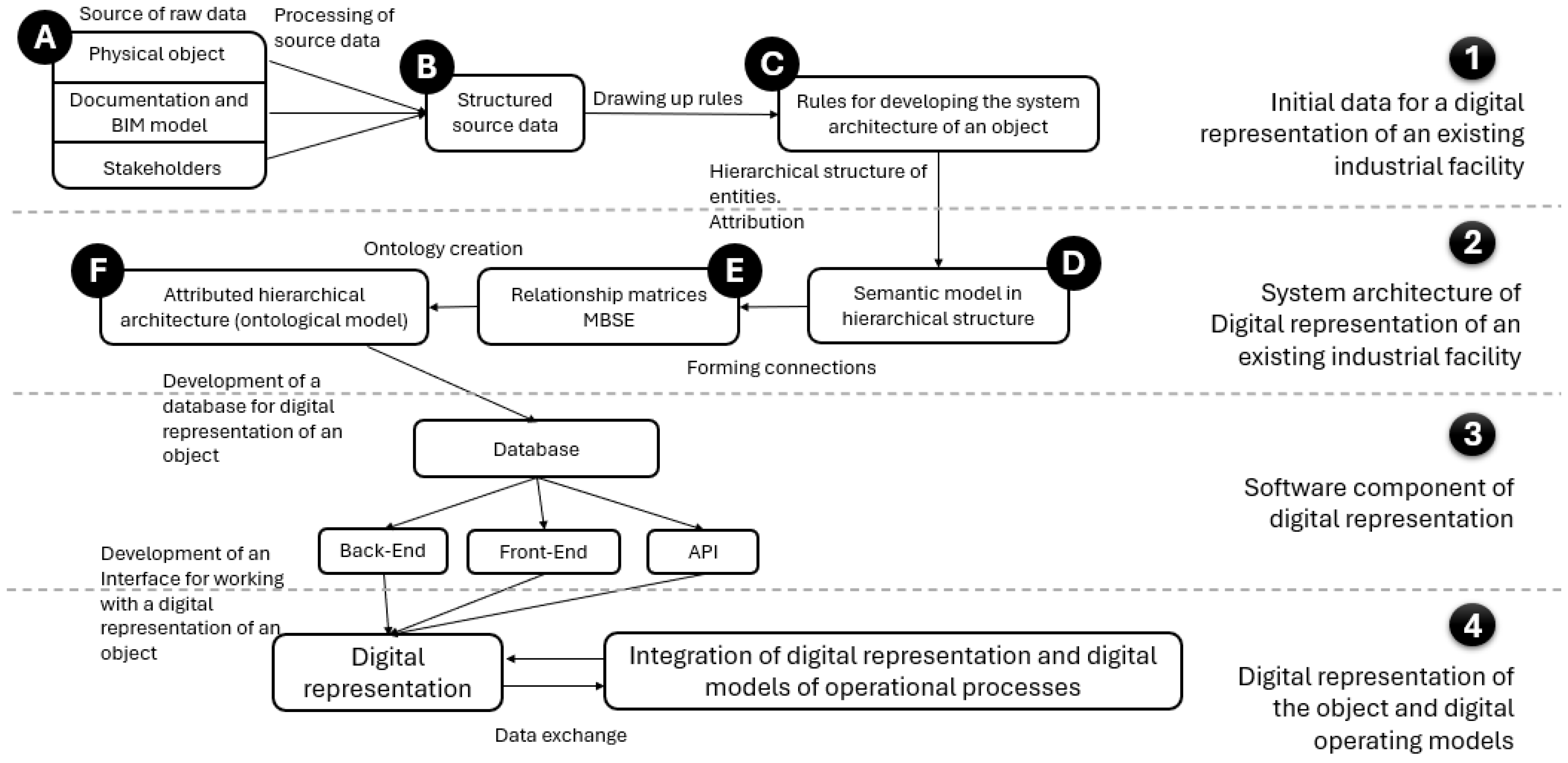
4.1. Method Algorithm

In this section, we propose an algorithm that is not new in the classical sense but represents an assembly of methods and approaches adapted for the specific needs of reengineering existing industrial facilities. Although each component of the algorithm is based on well-known MBSE tools and ontological modeling, the key feature is their integration into a unified sequence of actions, which provides a way to solve the task of building system architecture. This algorithm was also tested on the example of a small hydroelectric power station to identify the characteristics of its use.
In accordance with the general outline of the system architecture from Section 4.2, an algorithm for constructing the system architecture of an existing industrial object has been developed (Figure 4). Figure 4 illustrates the methodology for creating digital representations of existing industrial objects, starting from the collection of initial data about the physical object, including documentation and input from stakeholders, through structuring these data, developing a semantic model, and forming an ontological model. The process includes creating a hierarchical structure of entities, developing a database, and integrating with software components to manage the digital representation, which ensures support for efficient modeling and operation of industrial objects. This method involves repeating various steps to refine the architecture until the desired accuracy and completeness of the representation are achieved. A detailed description of the algorithm and its justification are presented below.
General comments on the algorithm: All described steps of the algorithm are performed iteratively, meaning that at any step, if necessary, it is required to go back several steps to make changes. It is recommended to complete all the steps of the algorithm to produce a first draft of the system architecture. Subsequently, any imperfections in the system architecture will be identified, and the steps will need to be repeated until the desired result is achieved. Flaws in the architecture are identified based on comparison with the project implementation goals and must be resolved by balancing requirements and elements. If the goals and required level of detail are met, it is considered that there are no flaws. The determination of goal achievement and level of detail is performed by all stakeholders
In accordance with the requirements identified in Section 4.2, a method for constructing the system architecture of an existing industrial object for forming its digital representation has been developed:
1. Initial Data for Forming the System Architecture of an Existing Industrial Object in the Digital Space.
A. Sources of Initial Data
The first step involves collecting initial data about the existing industrial object (EIO). The sources of initial data are classified as follows:
  • Physical components and processes of the EIO;
  • Documentation of the EIO;
  • Information support of the EIO, including information models of the EIO’s infrastructure and technological equipment;
  • All stakeholders interacting with the EIO.
The initial data should be redundant, meaning that there are no restrictions during data collection, for example, in cases of duplication. Filtering of unnecessary and erroneous data is carried out in subsequent steps.
We can achieve the necessary level of information sufficiency, which is defined by the objectives and agreed upon by the stakeholders.
For these rules, it is necessary to identify additional features associated with the existing object, which are not accounted for in the general rules and principles of implementation. They depend on the specific case, as each industrial object is unique and requires more detailed specificity of the general rules
B. Processing (Structuring) Initial Data
After collecting the initial data,
  • Define the boundaries of the target system;
  • Annotate the collected initial data and classify them into groups corresponding to the entities used in the method for forming the system architecture: requirements, functions, components, and processes.
The annotation of the collected initial data is performed in accordance with the MBSE approach methodology, which involves structuring into four main groups: requirements, functions, components, and processes [86]. Data structuring can be performed using NLP tools followed by expert validation of the results, or solely by expert distribution. The justification for the distribution is the semantic content of the initial data.
Alongside the annotation, the system boundaries are defined. Boundary definition begins with identifying the layers of the subject areas to be involved. For example, for an EIO, these could be the layers of physical components and processes, as well as the operational layer. Data that do not belong to these layers and relate, for example, to the economic or logistical layer, should be marked as not included in the system but not discarded for potential use in subsequent iterations.
After defining the boundaries by layers, it is necessary to set the boundaries of the system in each of the four groups: requirements, functions, components, and processes. The system exists in each of these categories, and the boundaries in each must be determined.
After defining the boundaries by entity groups, the boundaries of detail must also be set, i.e., formal criteria for the maximum level of decomposition in each category must be provided.
Requirements are formalized conditions or capabilities that the system must provide. They can be functional, defining what the system should do, for example, a certain amount of produced goods, or non-functional, describing the characteristics of the system, such as reliability and safety.
Functions describe the operations or actions that the system performs to achieve its goals. They are related to the requirements and define what actions the system must take to meet those requirements.
Components are the physical or logical elements that make up the system. Physical elements are parts of the equipment and infrastructure of the EIO. Logical elements are software modules, databases, or interfaces.
Processes are sequences of operations or actions involving various functions and components aimed at achieving specific requirements.
Within the system architecture, these elements are interconnected. Requirements formulate goals, functions describe the actions that components must perform, and processes integrate everything into a whole, describing the interaction and sequence of work in the system.
The result of step B is digital information about the EIO, distributed into four groups: requirements, functions, components, and processes within defined system boundaries.
C. Formulation of System Architecture Development Rules
Next, it is necessary to compile a document containing rules for developing the system architecture of the project to ensure the consistency of actions of all project participants.
Based on the information obtained in the previous step and the principles of MBSE [47], rules for forming the EIO’s system architecture, considering its specifics, are developed. The document includes the following:
  • Procedures for validating initial data;
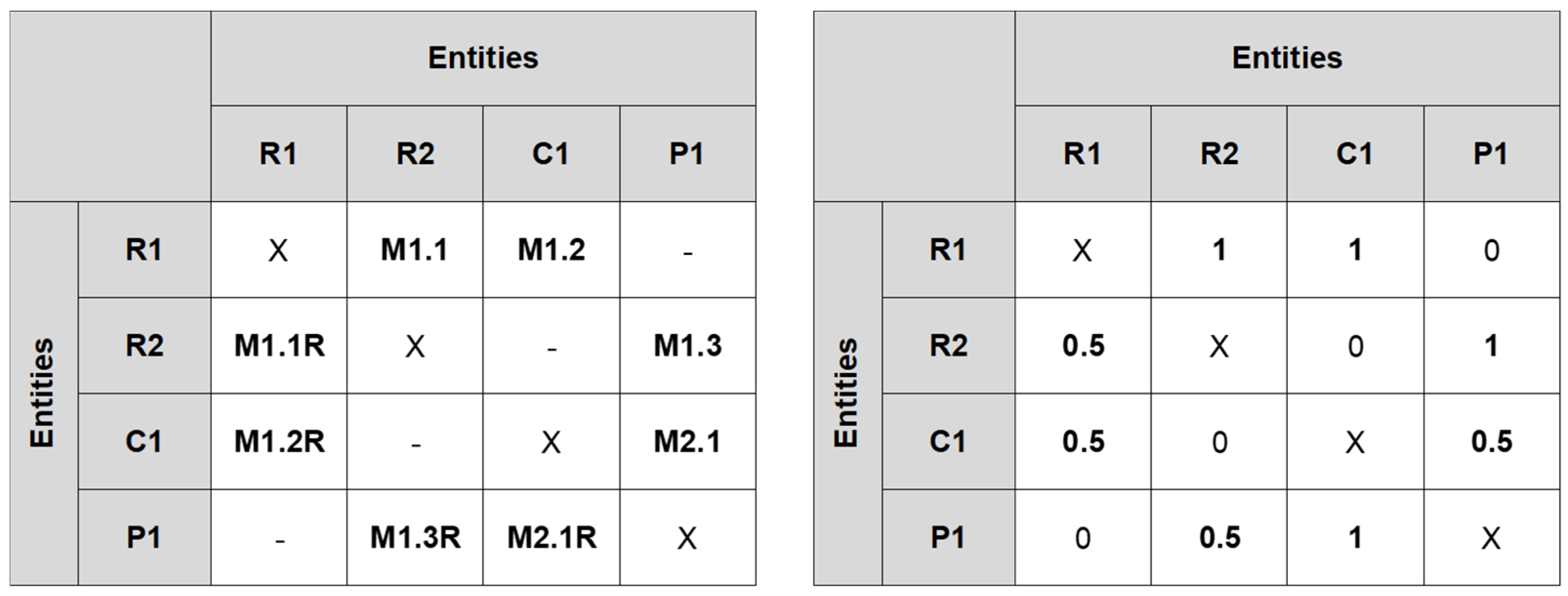
  • Rules for compiling the semantic model of the system;
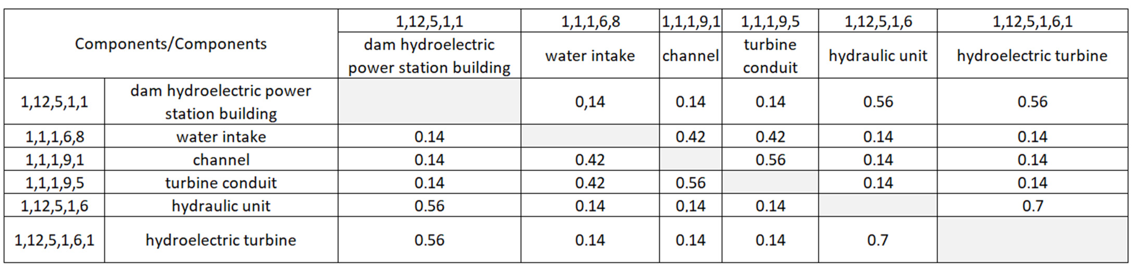
  • Rules for compiling entity relationship matrices;
  • Rules for forming the hierarchy of the system architecture;
  • Rules for assembling the system architecture;
  • Other rules as necessary.
Similar documents used in BIM modeling are EIR (Employer’s Information Requirements) and BEP (BIM Execution Plan). BEP and EIR describe the information requirements of the project. The existence of such documents in similar fields indicates the necessity of pre-agreed conditions for processing data about the EIO.
D. Compilation of the Semantic Model. Identification and Attribution of Entities
D1. Compilation of the Semantic Model in the Form of a Hierarchical Structure
Based on the groups obtained from the annotation of requirements, functions, components, and processes, entities for the semantic model are identified.
An entity in the system architecture is an individually identifiable element of the system that can be specified as a physical object or an abstract concept. Entities have unique attributes and characteristics that define their behavior and interaction within the system. In the context of the system architecture, each entity contributes to the functional and structural construction of the system, playing a specific role and interacting with other entities. They can be organized into hierarchical structures, where each level of the hierarchy reflects the nesting and dependence of entities on each other.
Each entity is entered into a dictionary containing definitions for each entity with the following columns. Dictionary is presented in our case in Section 4.2:
  • Serial number of the entity in the dictionary;
  • Entity number in the hierarchy;
  • Source of the semantic value of the definition;
  • Entity name;
  • Entity definition.
This step is necessary for two reasons:
  • Semantic unambiguity of the used entities;
  • Justification of the hierarchical arrangement of entities, as the definition includes an indication of the class to which the entity belongs;
  • Based on this dictionary, a semantic model is constructed. The dictionary contains definitions for all entities, including classes, subclasses, and attributes.
The semantic model is formed in the format of a hierarchical structure to formalize the description of all entities in the system architecture. Formats for displaying the hierarchical structure include XML, JSON, CSV, and others. Entities include the elements that make up the system architecture. The semantic model must include the following:
  • Hierarchical nesting, including classes, subclasses;
  • Entity identifier corresponding to the hierarchical nesting;
  • Semantic description of the entity, including attributes;
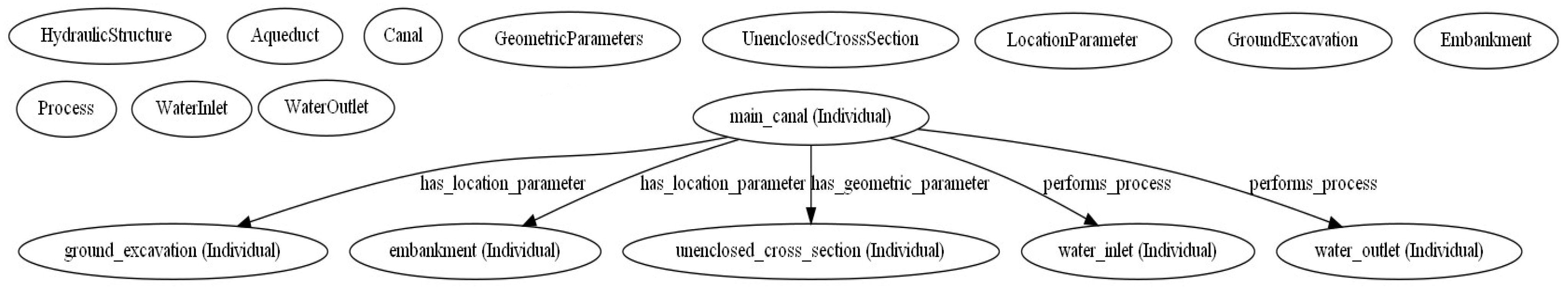
  • The semantic model is formed for the considered system and for the subject area.
Such semantic models are constructed for the four groups identified earlier: requirements, functions, components, and processes.
A hierarchical system implies a system in which one component is nested within another. Creating a hierarchical structure allows defining the constituent components of elements and tracing the nesting of these elements.
When compiling the hierarchical structure for the considered system, the main question is: “Can this EIO entity exist separately, or does it only make sense within the framework of the considered EIO?” For example, a support grid is useless without a water canal and a hydroelectric station, so in the hierarchical structure, it will belong to the components group and be at the third level of the hierarchy. At the same time, in the subject area semantic model, it will be an element in another place in the hierarchy.
D2. Attribution of Semantic Model Elements
After compiling the semantic model, the attributes of the system architecture entities are identified. An attribute is a constant characteristic of an entity that does not change during processes. The value of an attribute is a characteristic that changes over time during processes. For example, for the entity “Reinforced concrete wall in room A”, the class will be “Wall”, the attribute “Location”, the attribute value “Room A”, the attribute “Material type”, and the attribute value “Reinforced concrete”.
At the same time, attributes and their values are classes and subclasses from the subject area semantic model. For example, in the ontological model for the construction domain, there will be a class “Material”, a subclass “Material type”, and subclass values “Reinforced concrete”, “Aerated concrete”, etc. In the ontological model for the considered system, there will be several entities with the attribute “Material” and the value “Reinforced concrete”.
The key difference between an ontological model and a semantic model is the presence of relationships between the entities of the studied system. Although relationships partially appear due to attribution, this is not the final form of their representation.
E. Identification of Relationships between Semantic Model Elements
E1. Formation of Entity Relationship Matrices
Formation of entity relationship matrices in accordance with the MBSE approach. Relationships between entities are described in the form of a relationship matrix based on the compiled semantic model (point D). In the classic MBSE approach, it involves forming a set of key system data, grouped into the following categories:
  • Requirements (R);
  • Functions (F);
  • Components (W);
  • Processes (P).
After recording data in these groups, pairwise influence matrices are formed to identify relationships between system functions, processes, components, and requirements. The following types of matrices are formed: R–R, F–F, W–W, P–P, R–F, R–W, R–P, F–W, F–P, and W–P (Figure 5). An influence or relationship matrix is a table with dimensions equal to the number of entities at all hierarchy levels. Rows and columns contain entities, and the matrix body records descriptions of entity relationships. Stakeholders determine relationships between entities considering entity attributes and fill in the matrix cells. Examples of matrices are provided in Section 5 part E1.
E2. Recording Relationships in Matrix Cells
At the intersections of entities that make up the matrix, cells are formed where relationships between elements are recorded. Relationships between elements are formalized connections established between various entities, essentially indicating how elements influence each other. Relationships can be represented in the form of models, which may be as follows:
  • Mathematical;
  • Computer-based;
  • Digital;
  • Semantic;
  • Ontological;
  • Other types.
If representing relationships in the form of models is not feasible due to certain circumstances, they can be recorded as textual descriptions, although their further use will be challenging.
To display relationships when constructing the system architecture in the digital space, mathematical and computer models will primarily be used, as relationships between entities need to be recorded in a machine-interpretable format.
To determine the relationships, the authors propose using ontological modeling principles. As mentioned earlier, a relationship (or connection) is an attribute whose value is another object. To determine relationships, it is identified which attributes in the semantic model of both the system and the subject area are the same. Then, relationships between elements are recorded in a meta-mathematical or computer model and visualized in the ontological model.
After determining the relationships, a classifier of models is formed. The classifier should include the following:
  • Model identifier;
  • Model name;
  • Semantic description of the model;
  • List of attributes and parameters used by the model;
  • The obtained classifier is agreed upon by all stakeholders.
Examples of matrices are provided in Section 5 part E2.
E3. Using Matrix Cells to Record the Degree of Influence between Entities
The matrix cells can also be used to record the degree of influence between entities. These are criteria for forming pairwise matrices, aimed at answering the question, “Is it necessary to consider the relationships between the given elements of the system decomposition, or can they be disregarded?” This criterion allows significantly reducing the volume of analysis and modeling, ensuring necessary and sufficient model content. Other relationships may be considered in subsequent iterations, but they are not needed at the stage of system description and model development.
The authors propose two methods for forming criteria:
  • Expert-based;
  • Based on the level of component nesting in the hierarchical model.
The criteria are used during expert evaluation, based on which the pairwise matrices are formed. This method is applied when the hierarchical model has not been constructed. The authors propose three conditional gradations:
0—No connection or influence between the entity and the considered entity;
0.5—Implicit or indirect connection through other entities, or uncertainty regarding the presence of a connection;
1—A connection and direct influence exist.
The authors also propose a method for forming criteria in influence matrices based on the degree of component nesting. The more entities are nested within each other, the greater their influence coefficient on each other. The coefficient is calculated based on the total level of nesting. The total level of component nesting is taken as 100%, and the influence coefficient for each level is taken as an equal part of these 100%. For example, if the matrix contains entities with a maximum nesting level of 7, the significance coefficient for one level is 0.14 (100/70.01 ≈ 0.14). Thus, for the entity “Hydro unit” with the index in the hierarchy1,12,5,1,6 the influence coefficient concerning the entity “Vertical propeller hydro turbine” with the index 1,12,5,1,6,1,4 will be 0.7 (5 common levels 50.14 = 0.7); and for the entity “Water intake” with the index 1,1,1,6,8, it will be 0.14 (1 common level 1 × 0.14 = 0.14). Examples of matrices are provided in Section 5 part E3.
E4. Repeated Iterations and Balancing Stakeholder Requirements
The result of the previous steps is checked for balancing stakeholder requirements and other entities. This means determining the presence of missing, redundant entities, or incorrect semantics.
An important aspect of repeated iterations is identifying missing entities, their semantics, attributes, and relationships for which information is absent or incomplete. All this should be restored based on the existing data set, semantic models, and matrices. For example, in the system, there are four components, five processes, and seven requirements. For two requirements in the current system architecture, necessary components (with known attributes) are missing, but the processes corresponding to these requirements are described in the system architecture. Additionally, one component is not linked to requirements and processes. This means that the task of repeated iteration includes restoring the description of missing components based on their relationships with other entities, as well as refining the requirements and processes related to the “redundant” component.
F. Assembly of System Architecture. Compilation of the Ontological Model
The ontological model is formed based on the semantic model and entity relationship matrices. Relationships between elements of the ontological model (i.e., attributed entities) are reflected in the form of mathematical, computer, digital, and other models, depending on the nature of the relationship. The use of ontologies is primarily dictated by the need to record relationships between three or more objects. The ontological model must include the following:
  • Model identifier;
  • Model name;
  • Semantic description of the model;
  • List of attributes and parameters used by the model.
The ontological model is necessary to display all relationships between elements in one place. Section 3 on materials and methods describes the principles of constructing the ontological model. The ontological model includes entities that are identifiable elements of the system, which can be physical objects or abstract concepts. It is formed based on a semantic model and entity relationship matrices. The model consists of entities with unique identifiers, names, semantic descriptions, attributes, attribute values, and relationships. It organizes these entities into a hierarchical structure, reflecting their nesting and dependencies. Additionally, the model includes a classifier of models, which helps to ensure a comprehensive and integrated representation of the system’s architecture.
The fundamental difference between an ontological model and system architecture lies in their focus and scope.
An ontological model primarily provides a formalized, structured representation of entities within a system, detailing their attributes, relationships, and hierarchical organization. Its main purpose is to ensure semantic clarity and interoperability of data, facilitating precise communication and integration across different systems and stakeholders. The ontological model emphasizes the semantic description of elements and their interconnections, often using standardized languages and formats to support reasoning and data exchange.
On the other hand, system architecture encompasses the broader structural and functional design of a system. It includes not only the description of components and their relationships but also the principles, guidelines, and rules that govern the system’s behavior, performance, and lifecycle. System architecture is concerned with both the physical and logical aspects of a system, addressing how the system meets its requirements and performs its functions within given constraints. It involves a more comprehensive view, integrating various perspectives such as technical, operational, and strategic considerations to achieve a cohesive and optimized system design.

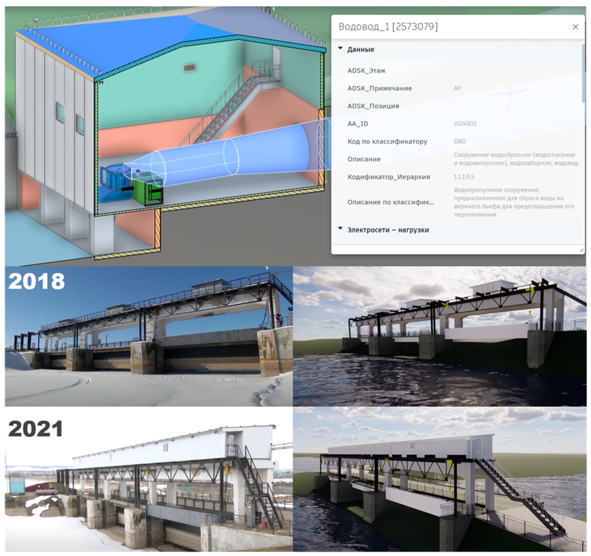
4.2. Testing the Method for Constructing System Architecture for a Small Hydroelectric Power Plant

This methodology was tested in the development of a system architecture to create a digital representation of a small hydroelectric power plant (HPP). The small HPP is a dam building located on the shore of a reservoir, with a design capacity of approximately 500 kW.
1. Initial Data for Forming the System Architecture of an Existing Industrial Object in the Digital Space
A. Sources of Initial Data
The following types of sources were used as initial data:
  • Design documentation for the small HPP, including drawings, specifications, and photographs of the structure;
  • Open data: terrain modeling using software;
  • Construction information classifier.
Based on these data, an information model (BIM model) was constructed, taking into account changes to the object over time (Figure 6). The components of the BIM model were then attributed according to the construction information classifier. Thus, the initial data were supplemented with the BIM model of the small HPP.
When constructing the BIM model of the object and attributing it according to the construction information classifier, the following conclusion was reached: despite having a complete BIM model of the object, it was not possible to obtain the system architecture for this object. The reason for this is the insufficient amount of data; specifically, merely attributing 3D elements of the object does not provide a representation of the system architecture. This observation confirms the necessity of applying the methodology for creating the system architecture of the existing industrial object (EIO).
B. Processing (Structuring) Initial Data
To fulfill point B—structuring the initial data—all data about the object were manually processed and distributed into four groups: requirements, functions, components, and processes. Parts of the documents containing information about these groups were identified. As a result, a document was created, consisting of the following:
  • Requirements, functions, components, and processes for the considered object;
  • Identifiers of the highlighted fragments;
  • Sources of the fragments;
  • Content of the fragments.
C. Formulating Rules for Developing the System Architecture of the Project
Next, in fulfilling point C, the main rules for structuring information were determined. For example:
The index of elements in the semantic scheme was formed based on the level of nesting of entities. For instance, for level 1 entities, the initial digit of the index was 1. For entities nested in level 1, the index was 1.1, 1.2, and so on, where the second digit reflected the sequential number of the entity.
A comprehensive document with rules for developing the system architecture of the project was not compiled, as the scale of the project did not require it.
2. System Architecture of an Existing Industrial Object for the Formation of Its Digital Representation
D. Creating the Semantic Model: Identifying Entities and Attributing Them
D1. Creating the Semantic Model in a Hierarchical Structure Format
A dictionary was compiled (Figure 7) containing definitions for each entity with the following columns:
  • Sequential number of the entity in the dictionary;
  • Number of the entity in the hierarchy;
  • Source of the semantic value of the definition;
  • Name of the entity;
  • Definition of the entity.
This step is necessary for two reasons:
  • Semantic unambiguity of the used entities;
  • Justification of the hierarchical placement of entities, as the definition indicates to which class the entity belongs.
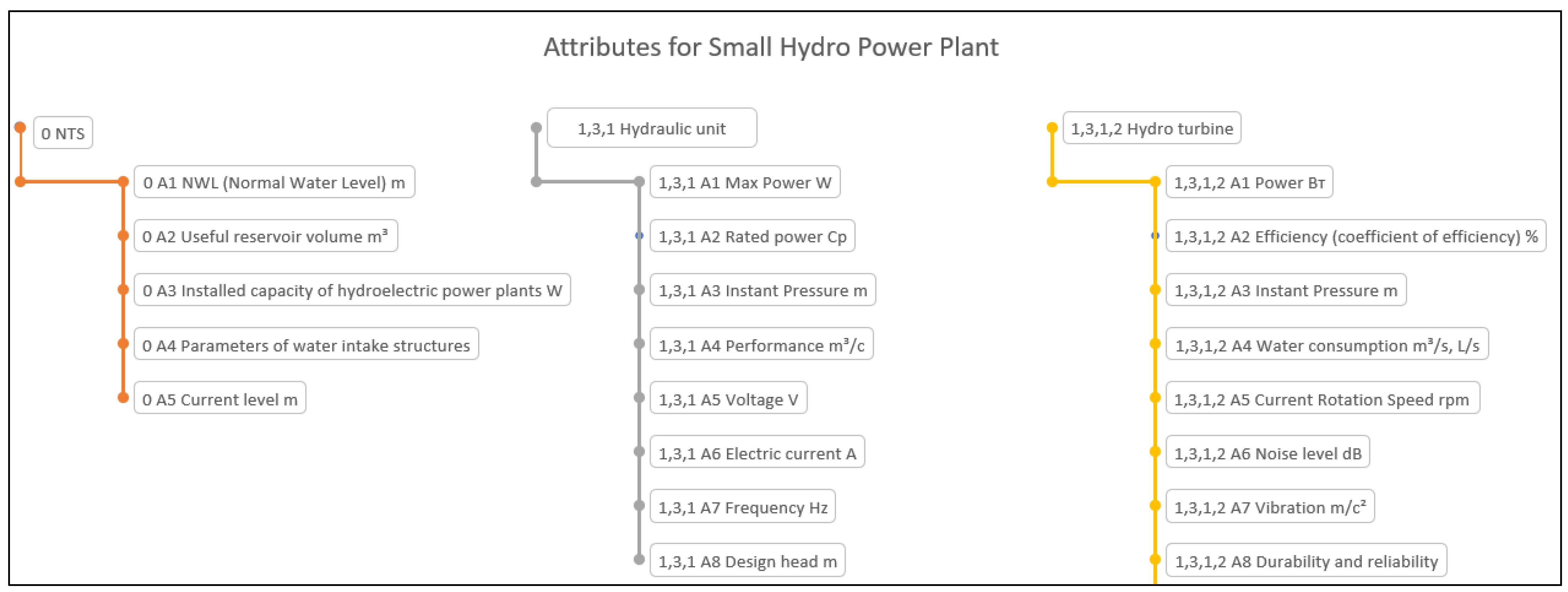
Based on this dictionary, a semantic model in a hierarchical structure is built for the subject area of hydraulic engineering, with boundaries defined for the small hydroelectric power plant system.
In this case, the semantic model was compiled in Excel and then converted to CVS. Block 1 in Figure 8 shows how entities are recorded by levels of the hierarchy. Block 2 in Figure 8 shows the final view of the semantic model, convenient for visual perception.
Such schemes were constructed for four groups: requirements, functions, components, and processes. Figure 8 provides an example for the components group.
Next, a semantic model is constructed within the boundaries of the studied system. All entities of the semantic model within the boundaries of the studied system are taken from the semantic model of the subject area. If an ontological model of the subject area has been developed, entities are taken from the ontological model of the subject area.
Using Excel in this case is the most convenient, as entities (including classes, subclasses, and attributes) are defined once in the dictionary with definitions, and then referenced in the semantic models. This method allows for data management across different systems.
Such schemes were constructed for four groups: requirements, functions, components, and processes. Attribution of elements was not performed. Figure 9 provides an example for the components group. The difference between the semantic model of the subject area and the semantic model of the studied system lies in the number of entities that will be used in constructing the system architecture of the existing industrial object (EIO).
The hierarchy provides for two-level coding of elements. The first level of coding is object-based, indicating the unique code of the element. It is necessary to include identical components in the hierarchical structure, which may be in different subsystems and at different levels. In this structure, the object-based code is present only in the information model of the small hydroelectric power plant, as there are no repeating elements. The second level of coding is hierarchical, showing how elements are nested within each other.
D2. Attributing Elements of the Semantic Model
To identify entities and attributes, a table was created (Figure 10) that listed the main parameters of each entity and their association with requirements, functions, components, and processes. Each entity was considered individually.
Next, the attribution of entities in the semantic model was separated into distinct schemas (Figure 11).
E. Identifying Relationships Between Elements of the Semantic Model
E1. Forming the Entity Relationship Matrix
All matrices of mutual influence of entities were compiled in accordance with the MBSE approach. Examples of the “components–components” and “requirements–functions” matrices are provided below.
Components–Components Matrix.
For the “components-components” matrix (Figure 12), the influence of components on each other was determined based on the hierarchy of these components. The deeper a component is nested within another, the greater its influence. The matrix is symmetric, as the relationship is mutual and bidirectional. Based on these data, it is possible to determine which component is most critical to another component, and accordingly, determine the degree of detail needed during design. For instance, when reconstructing a hydro unit, it is essential to first determine the condition of the hydraulic turbine, or when modeling the water conduit, consider it in conjunction with the intake and channel. An example of calculating cell values is provided in Section 4.2 part E3.
Requirements–Functions Matrix.
When examining the matrix (Figure 13) that matches requirements and functions, we analyze the degree of mutual influence of the elements’ relationships. This allows us to determine which requirements need to be prioritized when performing certain functions. In this case, the coefficients were assigned based on expert assessment. Here, 0 (white color in the table) indicates the absence of a direct relationship and influence of the element and all its components on the considered element, while 0.5 (yellow color in the table) indicates an indirect or implicit relationship through other elements, and 1 (green color in the table) indicates a direct relationship and influence. Further refinement of relationships is possible as components and parameters of the system and functions are specified.
E2. Recording Relationships in the Cells of Relationship Matrices
To represent the relationships between entities, a classifier of mathematical models was created. The classifier consisted of the following columns:
Entity for which mathematical models are built
Attributes. Additionally, attributes of mathematical models were divided into systemic—describing relationships and physical—measurable characteristics
  • Attribute name;
  • Unit of measurement;
  • Designation (symbol);
  • Attribute value range;
  • The mathematical models themselves;
  • Attribute type (textual/numerical);
  • Components included in the mathematical model. Components are also taken from the semantic model of the subject area or system.
As an example, the description for the entity “Hydraulic Turbine” is provided (Figure 14).
F. Assembling the System Architecture: Creating the Ontological Model
Initially, Portage was used for ontology development, but it was later replaced by Python with the owlready2 and graphviz libraries to ensure flexibility in development (Figure 15). The initial data for the demonstration part of the ontological model are shown in Figure 10.
Classes are written in ovals, and edges represent the relationships that exist between entities. The construction of a complete ontological model for the subject area and the studied system was not carried out within the framework of this method testing.

5. Discussion

5.1. Comparison with Existing Methods

While it is challenging to conduct a detailed comparison with developed methodologies within the scope of this article, it is possible to identify several key principles mentioned in each methodology and compare them exclusively with these principles.
Comparison with these established standards was carried out in order to show the absence of fundamental contradictions, since the indicated approaches are general and verified, and our proposal is a separate way of applying these principles and therefore the proposed method must contradict them.

5.1.1. Comparison with INCOSE Systems Engineering Principles

Below are the formulations of the principles of systems engineering published by INCOSE [87] and a commentary on the compliance of the developed method with each principle:
“Systems engineering in application is specific to stakeholder needs, solution space, resulting system solution(s), and context throughout the system life cycle”. The algorithm accounts for balancing the requirements of all stakeholders and aligning the system architecture (SA) at key stages of its development. The solution space is represented through entity relationship matrices, and context is provided by the semantic model and rules formulated based on the goals of SA development.
“Systems engineering has a holistic system view that includes the system elements and the interactions amongst themselves, the enabling systems, and the system environment”. The proposed algorithm clearly defines the system boundaries and its components in classes of requirements, functions, components, and processes, and composes an entity hierarchy along with relationship matrices. The interactions of system elements with the overall system and the system environment are considered in the rules.
“Systems engineering influences and is influenced by internal and external resource, political, economic, social, technological, environmental, and legal factors”. This principle is not fully accounted for in the algorithm due to its application boundaries—complex technical systems of existing industrial enterprises, unlike this principle, which is designed for a broader and more general case. However, this principle should be considered when identifying stakeholders and forming rules for SA development in the context of the specific task.
“Both policy and law must be properly understood to not overly constrain or under constrain the system implementation”. This principle concerns the stage of forming SA development rules, which does not contradict it. Overall, this statement should be considered in the tasks of balancing entities and stakeholder requirements.
“The real system is the perfect representation of the system (only complete, full, or perfect representation of the system is the system itself)”. This principle underlies the algorithm since we are dealing with an existing object, and the most accurate information about the EIO can be obtained from the data source—the EIO itself.
“A focus of systems engineering is a progressively deeper understanding of the interactions, sensitivities, and behaviors of the system, stakeholder needs, and its operational environment”. This principle is implemented through an iterative approach to SA development with constant improvement in understanding the interactions, system components, and stakeholder needs.
“Systems Engineering addresses changing stakeholder needs over the system life cycle”. This principle is ensured by the balancing matrix tools and the ability to change individual requirements over time, embedded in the SA structure formed using the proposed algorithm.
“Systems engineering addresses stakeholder needs, taking into consideration budget, schedule, and technical needs, along with other expectations and constraints”. This principle is considered at all stages, from collecting initial data from stakeholders to the final formation and agreement of the SA.
“Systems engineering decisions are made under uncertainty accounting for risk”. This principle also underlies the developed method. The problem statement itself indicated that information about existing objects is almost always incomplete and partially erroneous.
“Decision quality depends on knowledge of the system, enabling system(s), and inter-operating system(s) present in the decision-making process”. The developed method does not contradict this principle, but the method’s boundaries do not include decision-making procedures for a functioning system and its interaction with external systems. These aspects should be considered in the formation of rules based on the goals of SA development.
“Systems engineering spans the entire system life cycle”. The method is designed so that the resulting SA is adaptable and can be used throughout the entire life cycle.
“Complex systems are engineered by complex organizations”. The method does not contradict this principle and considers the need for the involvement of all stakeholders, which increases with the complexity of the system. This principle should also be considered in the rules, as the more complex the system and organization, the more aspects need to be regulated by rules for effective operation.
“Systems engineering integrates engineering and scientific disciplines in an effective manner”. The method is limited to the subject areas of the EIO and does not include the organizational component. However, it provides for the integration of system components from various engineering disciplines in the SA.
“Systems engineering is responsible for managing the discipline interactions within the organization”. In the algorithm, the formation of rules, in which these interactions must be formalized, is a separate stage.
“Systems engineering is based on a middle range set of theories”. The method considers the need to attribute entities, i.e., bring them to a mathematical representation, considering the possible different nature of attributes from various subject areas applicable to the same entity.
In conclusion, the developed method complies with all principles presented by INCOSE and provides a refined action algorithm for constructing the system architecture for a specific application domain in existing industrial objects to form a digital representation.

5.1.2. Comparison with TOGAF Architecture Design Principles

The TOGAF standard [88] presents Core Concepts, which form the basis of the entire methodology. These concepts and a comparison with the developed method are provided below.
TOGAF’s definition of architecture is as follows: the structure of components, their inter-relationships, and the principles and guidelines governing their design and evolution over time. It also provides a definition per ISO/IEC/IEEE 42010: 2022 [27]: the fundamental concepts or properties of a system in its environment embodied in its elements, relationships, and principles of its design and evolution. The definition used for SA formed as a result of applying the method corresponds to these definitions, as it includes system elements, relationships, and rules.
Subsets of architectures in the TOGAF standard include business architecture, data architecture, application architecture, and IT architecture (technology architecture). In our case, the concept of system architecture is used, which integrates all the above architectures into a single structure. However, the boundaries of the study and method application currently include only the technical and operational components.
The architecture development method algorithm differs from the one we proposed. The TOGAF standard proposes a development sequence with different actions, primarily focused on establishing rules and management procedures, with an emphasis on balancing stakeholder requirements at all stages.
If we generalize the goals of the elements of the TOGAF algorithm, they align with the goals of the stages of our proposed algorithm (rule development, entity identification, data collection, defining goals and stakeholders, requirement balancing). However, this approach can be very challenging to apply to existing technical systems. Its sequence is tailored specifically for enterprise architecture and does not fully consider systematics and is difficult to adapt to technical systems. Our method addresses a specific technological domain.
TOGAF entities analogs are Deliverables, Artifacts, and Building Blocks. Artifacts are catalogs and matrices, and blocks are individual architecture clusters that are verified and reusable. Blocks can be of different levels of detail. The product is the final representation of the enterprise result, presented in the architectural repository as a model, standard, or snapshot of the enterprise architecture at a given time.
The TOGAF standard has a unique term—Enterprise Continuum. It reflects a global view of the architecture, relative to which all components are considered. There is no direct analog in the developed algorithm; however, in our case, this concept is effectively replaced by the systems engineering methodology, providing a systematic understanding of the architecture.
The architectural repository mentioned in the standard corresponds to the semantic model used in our method. An independent entity in the TOGAF approach is Establishing the Architecture Capability as an Operational Entity. Essentially, this is a high-level representation of the enterprise’s functions, which is considered in our algorithm alongside requirements, processes, and components.
In summary, the same principles of system architecture construction are used as in the proposed algorithm, but the application domain of the principles and architecture differs, leading to differences in individual procedures.

5.2. Limitations and Challenges in Applying the Method Identified during Testing on a Small HPP

The main challenges in applying the method were as follows:
Manual data processing is extremely labor-intensive. To work effectively, Natural Language Processing (NLP) methods need to be applied. The application of NLP involves two key aspects: automatic sorting of data into requirements, functions, components, and processes, and automation of creating semantic and ontological models.
A ready-made framework or software for creating the system architecture is required. However, when testing various software for creating system architecture, developing custom frameworks in Excel proved to be the most convenient. This indicates two things: the method itself needs further refinement, as the inconvenience of using system architecture software was due to a lack of flexibility; tools with high flexibility and customization are necessary when developing system architecture.
Ontological models of subject areas are needed. The availability of open attributed semantic models in a hierarchical format would significantly facilitate the process of developing system architecture. The hierarchical component of the semantic model is primarily driven by the need for machine interpretability of data, as incorporating ontological models into operational process models requires interoperable digital data content.
Creating the system architecture involves developing an ontological model of the subject area and an ontological model of the developed system.
Assessing the relationships between entities significantly simplifies the system architecture modeling process, allowing for the identification of the most critical parts for modeling.
An important task related to the system architecture of existing facilities is the development of a mechanism for cognitive elements to collect data from these facilities. This includes perception and analysis systems for photos, audio, documentation, and data, similar to those proposed in the concept of cognitive digital twins. This task was not addressed in the present article and remains a subject for further research.
Potential advantages of the method include the ability to find unknown system elements and constraints during balancing. The method is also quite adaptive due to the customization of local rules, which take into account the specifics of a particular object. These same local rules can also be considered potential disadvantages of the method since they can complicate the procedure and are not fully specified. Future studies should probably pay attention to what exactly can be specified in such rules and what cases can occur in different industries.

6. Conclusions

This research developed and tested a method for constructing the system architecture of existing industrial objects using Model-Based Systems Engineering (MBSE) principles. The methodology is a digital engineering tool designed to create an accurate digital representation of an object. The study showed that applying MBSE in the context of digital transformation for existing industrial objects can significantly enhance the understanding of their system architecture.
The key achievement of this work is the creation of a methodology for developing the system architecture of existing industrial objects. This method allows for the identification and classification of components and the determination of their interrelationships.
Testing the method on a small hydroelectric power plant demonstrated its effectiveness in organizing and systematizing data, which is crucial for creating a complete digital representation of the object. The method was also evaluated against MBSE principles and enterprise architecture frameworks such as TOGAF and INCOSE.
Despite the method’s promise, several challenges were encountered during its implementation. The manual processing of data proved to be labor-intensive, highlighting the need for automation through Natural Language Processing (NLP). Additionally, the limited flexibility of existing software for creating system architectures suggests a need for specialized frameworks that can adapt to specific project requirements and facilitate the integration of ontological models. Issues with insufficient initial data, difficulties in data attribution, and the need for multiple iterations to achieve optimal results were also identified, indicating a need for methodological improvements.
In summary, the methodology for creating system architecture for existing industrial objects offers a valuable digital engineering tool for generating accurate digital representations. However, its effective application requires ongoing development in data collection and processing methods, as well as the creation of specialized frameworks to support these processes.

Author Contributions

Conceptualization, V.B. and V.Y.; methodology, V.B.; validation, A.M., V.K., E.M. and V.B.; formal analysis, V.K., A.M. and E.M.; data curation, V.K., V.B. and N.S.; investigation, V.K., A.M., N.S. and A.B.; writing—original draft preparation, V.B., V.K. and A.M.; writing—review and editing, V.Y., V.K., A.M., E.M., V.B., A.B. and N.S.; visualization, V.K., N.S., E.M. and A.M.; supervision, V.B.; project administration, V.Y., V.B. and A.B.; funding acquisition, V.Y. and A.B. All authors have read and agreed to the published version of the manuscript.

Funding

The research is partially funded by the Ministry of Science and Higher Education of the Russian Federation as part of the World-class Research Center program: Advanced Digital Technologies (contract No. 075-15-2022-311 dated 20 April 2022).

Data Availability Statement

The data supporting the findings of this study are available from the corresponding author, Arina Mohireva ([email protected]), upon request.

Conflicts of Interest

The authors declare no conflict of interest.

References

  1. Caiza, G.; Sanz, R. Digital Twin to Control and Monitor an Industrial Cyber-Physical Environment Supported by Augmented Reality. Appl. Sci. 2023, 13, 7503. [Google Scholar] [CrossRef]
  2. Segovia, M.; Garcia-Alfaro, J. Design, Modeling and Implementation of Digital Twins. Sensors 2022, 22, 5396. [Google Scholar] [CrossRef] [PubMed]
  3. Tekinerdogan, B. On the Notion of Digital Twins: A Modeling Perspective. Systems 2023, 11, 15. [Google Scholar] [CrossRef]
  4. Feng, Y.; Zou, Q.; Zhou, C.; Liu, Y.; Peng, Q. Ontology-Based Architecture Process of System-of-Systems: From Capability Development to Operational Modeling. Appl. Sci. 2023, 13, 5419. [Google Scholar] [CrossRef]
  5. Zeng, R.; Shi, J.J.S.; Wang, C.; Lu, T. Integrating As-Built BIM Model from Point Cloud Data in Construction Projects. Eng. Constr. Archit. Manag. 2023; ahead-of-print. [Google Scholar] [CrossRef]
  6. Han, S.H.; Zhang, H. Progress and Prospects in Industrial Heritage Reconstruction and Reuse Research during the Past Five Years: Review and Outlook. Land 2022, 11, 2119. [Google Scholar] [CrossRef]
  7. Naugolnova, I. Business Process Reengineering of the Existing Enterprise: Evolutionary and Radical Approaches. In Fundamental and Applied Scientific Research in the Development of Agriculture in the Far East (AFE-2022); Lecture Notes in Networks and Systems; Springer: Cham, Switzerland, 2024; Volume 733, pp. 487–496. [Google Scholar]
  8. Nadkarni, S.; Prügl, R. Digital Transformation: A Review, Synthesis and Opportunities for Future Research. Manag. Rev. Q. 2021, 71, 233–341. [Google Scholar] [CrossRef]
  9. Stoewer, H. Perspectives on SE, MBSE, and Digital Engineering: Road to a Digital Enterprise. In Handbook of Model-Based Systems Engineering; Springer: Cham, Switzerland, 2023; pp. 1–37. [Google Scholar]
  10. Maleki, S.; Jazdi, N.; Ashtari, B. Intelligent Digital Twin in Health Sector: Realization of a Software-Service for Requirements- and Model-Based-Systems-Engineering. IFAC-PapersOnLine 2022, 55, 79–84. [Google Scholar] [CrossRef]
  11. Bussemaker, J.H.; Ciampa, P.D. MBSE in Architecture Design Space Exploration. In Handbook of Model-Based Systems Engineering; Springer: Cham, Switzerland, 2023; pp. 1–41. [Google Scholar]
  12. Schindel, W.D. Pattern-Based Methods and MBSE. In Handbook of Model-Based Systems Engineering; Springer: Cham, Switzerland, 2023; pp. 151–194. [Google Scholar]
  13. Richard, C. System Architecture and Integration. In Understanding Semiconductors: A Technical Guide for Non-Technical People; Apress: Berkeley, CA, USA, 2023; pp. 155–174. ISBN 978-1-4842-8847-4. [Google Scholar]
  14. Alai, S.P. Evaluating ARCADIA/Capella vs. OOSEM/SysML for System Architecture Development. Master’s Thesis, Purdue University, West Lafayette, IN, USA, 2019. [Google Scholar]
  15. Jankovic, M.; Hein, A.M. Architecting Engineering Systems: Designing Critical Interfaces. In Handbook of Engineering Systems Design: With 178 Figures and 54 Tables; Springer: Cham, Switzerland, 2022; pp. 1–25. [Google Scholar]
  16. Celento, D. Innovate or Perish: New Technologies and Architecture’s Future; Harvard Design Magazine: Cambridge, MA, USA, 2007. [Google Scholar]
  17. Kirpes, B.; Danner, P.; Basmadjian, R.; de Meer, H.; Becker, C. E-Mobility Systems Architecture: A Model-Based Framework for Managing Complexity and Interoperability. Energy Inform. 2019, 2, 15. [Google Scholar] [CrossRef]
  18. Chen, H.; Wen, Y.; Zhu, M.; Huang, Y.; Xiao, C.; Wei, T.; Hahn, A. From Automation System to Autonomous System: An Architecture Perspective. J. Mar. Sci. Eng. 2021, 9, 645. [Google Scholar] [CrossRef]
  19. Jaakkola, H.; Thalheim, B. Architecture-Driven Modelling Methodologies. Front. Artif. Intell. Appl. 2011, 225, 97–116. [Google Scholar]
  20. Shea, G. NASA Systems Engineering Handbook Revision 2; NASA: Washington, DC, USA, 2017; Volume 1. [Google Scholar]
  21. Ryschkewitsch, M.; Schaible, D.; Larson, W. The Art and Science of Systems Engineering. Syst. Res. Forum 2009, 3, 81–100. [Google Scholar] [CrossRef]
  22. Sales, D.C.; Becker, L.B.; Koliver, C. The Systems Architecture Ontology (SAO): An Ontology-Based Design Method for Cyber–Physical Systems. Appl. Comput. Inform. 2022; ahead-of-print. [Google Scholar] [CrossRef]
  23. Mordecai, Y.; Fairbanks, J.; Crawley, E.F. Category-Theoretic Formulation of the Model-Based Systems Architecting Cognitive-Computational Cycle. Appl. Sci. 2021, 11, 1945. [Google Scholar] [CrossRef]
  24. Avci, C.; Tekinerdogan, B.; Athanasiadis, I.N. Software Architectures for Big Data: A Systematic Literature Review. Big Data Anal. 2020, 5, 5. [Google Scholar] [CrossRef]
  25. Borky, J.M.; Bradley, T.H. Using Prototypes, Verification, and Validation to Evaluate and Enhance System Architecture. In Effective Model-Based Systems Engineering; Springer: Cham, Switzerland, 2019. [Google Scholar]
  26. Korenhof, P.; Blok, V.; Kloppenburg, S. Steering Representations—Towards a Critical Understanding of Digital Twins. Philos. Technol. 2021, 34, 1751–1773. [Google Scholar] [CrossRef]
  27. ISO/IEC/IEEE 42010:2022; Software, Systems and Enterprise—Architecture Description. International Organization for Standardization: Geneva, Switzerland, 2022. Available online: https://www.iso.org/ru/standard/74393.html (accessed on 14 August 2024).
  28. Ofosu, R.; Hosseinian-Far, A.; Sarwar, D. Digital Twin Technologies, Architecture, and Applications: A Comprehensive Systematic Review and Bibliometric Analysis. In Advanced Sciences and Technologies for Security Applications; Springer: Cham, Switzerland, 2022. [Google Scholar]
  29. INCOSE SeBok. Available online: https://sebokwiki.org/wiki/Guide_to_the_Systems_Engineering_Body_of_Knowledge_(SEBoK) (accessed on 28 May 2024).
  30. Walden, D.; Shortell, T.; Rodler, G.; Delicado, B.; Mornas, O.; Yew-Seng, Y.; Endler, D. INCOSE Systems Engineering Handbook, 5th ed.; John Wiley & Sons: Hoboken, NJ, USA, 2023. [Google Scholar]
  31. Gerhard, D.; Cordero, S.S.; Vingerhoeds, R.; Sullivan, B.P.; Rossi, M.; Brovar, Y.; Menshenin, Y.; Fortin, C.; Eynard, B. MBSE-PLM Integration: Initiatives and Future Outlook. In Product Lifecycle Management. PLM in Transition Times: The Place of Humans and Transformative Technologies; IFIP Advances in Information and Communication Technology; Springer: Cham, Switzerland, 2023; Volume 667. [Google Scholar]
  32. Rozesara, M.; Ghazinoori, S.; Manteghi, M.; Tabatabaeian, S.H. A Reverse Engineering-Based Model for Innovation Process in Complex Product Systems: Multiple Case Studies in the Aviation Industry. J. Eng. Technol. Manag. 2023, 69, 101765. [Google Scholar] [CrossRef]
  33. Zhukov, A.; Berkutova, T.; Zhurenkov, D.; Kolosov, A.; Kheruvimova, S.; Kartsan, I. Methodology for Selecting Objects for Reverse Engineering at Oil and Gas Industry Enterprises. E3S Web Conf. 2024, 486, 04020. [Google Scholar] [CrossRef]
  34. Bolshakov, N.; Rakova, X.; Celani, A.; Badenko, V. Operation Principles of the Industrial Facility Infrastructures Using Building Information Modeling (BIM) Technology in Conjunction with Model-Based System Engineering (MBSE). Appl. Sci. 2023, 13, 11804. [Google Scholar] [CrossRef]
  35. Browning, T.R. Design Structure Matrix Extensions and Innovations: A Survey and New Opportunities. IEEE Trans. Eng. Manag. 2016, 63, 27–52. [Google Scholar] [CrossRef]
  36. Purohit, S.; Madni, A.M. A Model-Based Systems Architecting and Integration Approach Using Interlevel and Intralevel Dependency Matrix. IEEE Syst. J. 2022, 16, 747–754. [Google Scholar] [CrossRef]
  37. Hadaya, P.; Leshob, A.; de Verteuil, J.N. An Artifact for Learning the TOGAF Architecture Development Method. In Advances in E-Business Engineering for Ubiquitous Computing. ICEBE 2019; Lecture Notes on Data Engineering and Communications Technologies; Springer: Cham, Switzerland, 2020; Volume 41, pp. 435–449. [Google Scholar]
  38. Kotusev, S. TOGAF-Based Enterprise Architecture Practice: An Exploratory Case Study. Commun. Assoc. Inf. Syst. 2018, 43, 321–359. [Google Scholar] [CrossRef]
  39. Maulana, Y.M.; M Azmi, Z.R.; Arshah, R.A. Modeling of Strategic Alignment to Modify TOGAF Architecture Development Method Based on Business Strategy Model. Int. J. Adv. Sci. Eng. Inf. Technol. 2023, 13, 180–185. [Google Scholar] [CrossRef]
  40. Dietz, J.L.G.; Hoogervorst, J.A.P. A Critical Investigation of TOGAF—Based on the Enterprise Engineering Theory and Practice. In Advances in Enterprise Engineering V. EEWC 2011; Lecture Notes in Business Information Processing; Springer: Cham, Switzerland, 2011; Volume 79, pp. 76–90. [Google Scholar]
  41. Gerber, A.; le Roux, P.; Kearney, C.; van der Merwe, A. The Zachman Framework for Enterprise Architecture: An Explanatory IS Theory. In Responsible Design, Implementation and Use of Information and Communication Technology. I3E 2020; Lecture Notes in Computer Science (including subseries Lecture Notes in Artificial Intelligence and Lecture Notes in Bioinformatics); Springer: Cham, Switzerland, 2020; Volume 12066, pp. 383–396. [Google Scholar]
  42. Tao, Z.-G.; Luo, Y.-F.; Chen, C.-X.; Wang, M.-Z.; Ni, F. Enterprise Application Architecture Development Based on DoDAF and TOGAF. Enterp. Inf. Syst. 2017, 11, 627–651. [Google Scholar] [CrossRef]
  43. Aghamohammadpour, A.; Mahdipour, E.; Attarzadeh, I. Architecting Threat Hunting System Based on the DODAF Framework. J. Supercomput. 2023, 79, 4215–4242. [Google Scholar] [CrossRef]
  44. NATO Architecture Framework, Version 4. Available online: https://www.nato.int/cps/en/natohq/topics_157575.htm (accessed on 28 May 2024).
  45. UK GOV. A Summary of MODAF Views by Their Use and Data Types; UK Gov. Available online: https://assets.publishing.service.gov.uk/media/5a79ab89e5274a684690b3c9/20100602MODAFDownload12004.pdf (accessed on 28 May 2024).
  46. Hsiung, C.-H.; Chen, H.-J.; Tu, S.-W.; Ho, Y.-C. How the Federal Enterprise Architecture Framework (FEAF) Supports Government Digital Transformation. Enterp. Archit. Prof. J. 2020. Available online: https://eapj.org/feaf-and-government-digital-transformation/ (accessed on 20 June 2024).
  47. Bolshakov, N.; Badenko, V.; Yadykin, V.; Tishchenko, E.; Rakova, X.; Mohireva, A.; Kamsky, V.; Barykin, S. Cross-Industry Principles for Digital Representations of Complex Technical Systems in the Context of the MBSE Approach: A Review. Appl. Sci. 2023, 13, 6225. [Google Scholar] [CrossRef]
  48. Ayyildiz, E.; Taskin Gumus, A. Interval-Valued Pythagorean Fuzzy AHP Method-Based Supply Chain Performance Evaluation by a New Extension of SCOR Model: SCOR 4.0. Complex Intell. Syst. 2021, 7, 559–576. [Google Scholar] [CrossRef]
  49. Kusrini, E.; Helia, V.N.; Miranda, S.; Asshiddiqi, F. SCOR Racetrack to Improve Supply Chain Performance. Math. Model. Eng. Probl. 2023, 10, 915–920. [Google Scholar] [CrossRef]
  50. Qie, Y.; Bickel, S.; Wartzack, S.; Schleich, B.; Anwer, N. A Function-Oriented Surface Reconstruction Framework for Reverse Engineering. CIRP Ann. 2021, 70, 135–138. [Google Scholar] [CrossRef]
  51. Valerga, A.P.; Batista, M.; Bienvenido, R.; Fernández-Vidal, S.R.; Wendt, C.; Marcos, M. Reverse Engineering Based Methodology for Modelling Cutting Tools. Procedia Eng. 2015, 132, 1144–1151. [Google Scholar] [CrossRef]
  52. Kyaw, A.C.; Nagengast, N.; Usma-Mansfield, C.; Fuss, F.K. A Combined Reverse Engineering and Multi-Criteria Decision-Making Approach for Remanufacturing a Classic Car Part. Procedia CIRP 2023, 119, 222–228. [Google Scholar] [CrossRef]
  53. Lee, R.S.; Tsai, J.P.; Kao, Y.C.; Lin, G.C.I.; Fan, K.C. STEP-Based Product Modeling System for Remote Collaborative Reverse Engineering. Robot. Comput. Integr. Manuf. 2003, 19, 543–553. [Google Scholar] [CrossRef]
  54. Ariza-López, F.J.; Rodríguez-Avi, J.; Reinoso-Gordo, J.F.; Ariza-López, Í.A. Quality Control of “As Built” BIM Datasets Using the ISO 19157 Framework and a Multiple Hypothesis Testing Method Based on Proportions. ISPRS Int. J. Geo-Inf. 2019, 8, 569. [Google Scholar] [CrossRef]
  55. Pan, Y.; Zhang, L. Integrating BIM and AI for Smart Construction Management: Current Status and Future Directions. Arch. Comput. Methods Eng. 2023, 30, 1081–1110. [Google Scholar] [CrossRef]
  56. Gray, J.; Rumpe, B. On the Relationship between Models and Ontologies. Softw. Syst. Model. 2022, 21, 1271–1272. [Google Scholar] [CrossRef]
  57. Madni, A.M.; Madni, C.C.; Lucero, S.D. Leveraging Digital Twin Technology in Model-Based Systems Engineering. Systems 2019, 7, 7. [Google Scholar] [CrossRef]
  58. Madni, A.M.; Purohit, S.; Madni, C.C. Exploiting Digital Twins in MBSE to Enhance System Modeling and Life Cycle Coverage. In Handbook of Model-Based Systems Engineering; Springer: Cham, Switzerland, 2022. [Google Scholar]
  59. Henderson, K.; Salado, A. Value and Benefits of Model-based Systems Engineering (MBSE): Evidence from the Literature. Syst. Eng. 2021, 24, 51–66. [Google Scholar] [CrossRef]
  60. Niknam, M.; Karshenas, S. A Shared Ontology Approach to Semantic Representation of BIM Data. Autom. Constr. 2017, 80, 22–36. [Google Scholar] [CrossRef]
  61. Orellana, D.; Mandrick, W. The Ontology of Systems Engineering: Towards a Computational Digital Engineering Semantic Framework. Procedia Comput. Sci. 2019, 153, 268–276. [Google Scholar] [CrossRef]
  62. Horrocks, I. DAML+OIL: A Reason-Able Web Ontology Language. In Advances in Database Technology—EDBT 2002. EDBT 2002; Lecture Notes in Computer Science (including subseries Lecture Notes in Artificial Intelligence and Lecture Notes in Bioinformatics); Springer: Cham, Switzerland, 2002; Volume 2287. [Google Scholar]
  63. Knublauch, H.; Fergerson, R.W.; Noy, N.F.; Musen, M.A. The Protégé OWL Plugin: An Open Development Environment for Semantic Web Applications. In The Semantic Web—ISWC 2004. ISWC 2004; Lecture Notes in Computer Science (including subseries Lecture Notes in Artificial Intelligence and Lecture Notes in Bioinformatics); Springer: Cham, Switzerland, 2004; Volume 3298, pp. 229–243. [Google Scholar]
  64. McGuinness, D.L.; van Harmelen, F. OWL Web Ontology Language Overview. Available online: https://www.w3.org/TR/owl-features/ (accessed on 28 May 2024).
  65. Anikin, A.; Litovkin, D.; Kultsova, M.; Sarkisova, E.; Petrova, T. Ontology Visualization: Approaches and Software Tools for Visual Representation of Large Ontologies in Learning. In Creativity in Intelligent Technologies and Data Science. CIT&DS 2017; Communications in Computer and Information Science; Springer: Cham, Switzerland, 2017; Volume 754, pp. 133–149. [Google Scholar]
  66. AL-Aswadi, F.N.; Chan, H.Y.; Gan, K.H. From Ontology to Knowledge Graph Trend: Ontology as Foundation Layer for Knowledge Graph. In Knowledge Graphs and Semantic Web. KGSWC 2022; Communications in Computer and Information Science; Springer: Cham, Switzerland, 2022; Volume 1686, pp. 330–340. [Google Scholar]
  67. Swickline, C.; Mazzuchi, T.A.; Sarkani, S. A Methodology for Developing SoS Architectures Using SysML Model Federation. Syst. Eng. 2024, 27, 368–385. [Google Scholar] [CrossRef]
  68. Lu, J.; Ma, J.; Zheng, X.; Wang, G.; Li, H.; Kiritsis, D. Design Ontology Supporting Model-Based Systems Engineering Formalisms. IEEE Syst. J. 2022, 16, 5465–5476. [Google Scholar] [CrossRef]
  69. Yang, L.; Cormican, K.; Yu, M. Ontology-Based Systems Engineering: A State-of-the-Art Review. Comput. Ind. 2019, 111, 148–171. [Google Scholar] [CrossRef]
  70. Aman, S.S.; Agbo, D.D.A.; N’guessan, B.G.; Kone, T. Design of a Data Storage and Retrieval Ontology for the Efficient Integration of Information in Artificial Intelligence Systems. Int. J. Inf. Technol. 2024, 16, 1743–1761. [Google Scholar] [CrossRef]
  71. Eirinakis, P.; Lounis, S.; Plitsos, S.; Arampatzis, G.; Kalaboukas, K.; Kenda, K.; Lu, J.; Rožanec, J.M.; Stojanovic, N. Cognitive Digital Twins for Resilience in Production: A Conceptual Framework. Information 2022, 13, 33. [Google Scholar] [CrossRef]
  72. ur Rehman, A.; Ahmed, M.U.; Begum, S. Cognitive Digital Twin in Manufacturing: A Heuristic Optimization Approach. IFIP Adv. Inf. Commun. Technol. 2023, 676, 441–453. [Google Scholar] [CrossRef]
  73. Sierra, C.; Paul, S.; Rahman, A.; Kulkarni, A. Development of a Cognitive Digital Twin for Pavement Infrastructure Health Monitoring. Infrastructures 2022, 7, 113. [Google Scholar] [CrossRef]
  74. Arisekola, K.; Madson, K. Digital Twins for Asset Management: Social Network Analysis-Based Review. Autom. Constr. 2023, 150, 104833. [Google Scholar] [CrossRef]
  75. Khandoker, A.; Sint, S.; Gessl, G.; Zeman, K.; Jungreitmayr, F.; Wahl, H.; Wenigwieser, A.; Kretschmer, R. Towards a Logical Framework for Ideal MBSE Tool Selection Based on Discipline Specific Requirements. J. Syst. Softw. 2022, 189, 111306. [Google Scholar] [CrossRef]
  76. Baxter, G.; Sommerville, I. Socio-Technical Systems: From Design Methods to Systems Engineering. Interact. Comput. 2011, 23, 4–17. [Google Scholar] [CrossRef]
  77. Mirani, A.A.; Velasco-Hernandez, G.; Awasthi, A.; Walsh, J. Key Challenges and Emerging Technologies in Industrial IoT Architectures: A Review. Sensors 2022, 22, 5836. [Google Scholar] [CrossRef]
  78. Yi, K.J.; Jeong, Y.S. Smart Factory: Security Issues, Challenges, and Solutions. J. Ambient Intell. Humaniz. Comput. 2022, 13, 4625–4638. [Google Scholar] [CrossRef]
  79. Neumann, E.M.; Vogel-Heuser, B.; Fischer, J.; Diehm, S.; Schwarz, M.; Englert, T. Automation Software Architectures in Automated Production Systems: An Industrial Case Study in the Packaging Machine Industry. Prod. Eng. 2022, 16, 847–856. [Google Scholar] [CrossRef]
  80. Pedral Sampaio, R.; Aguiar Costa, A.; Flores-Colen, I. A Systematic Review of Artificial Intelligence Applied to Facility Management in the Building Information Modeling Context and Future Research Directions. Buildings 2022, 12, 1939. [Google Scholar] [CrossRef]
  81. What Is Digital-Twin Technology?|McKinsey. Available online: https://www.mckinsey.com/featured-insights/mckinsey-explainers/what-is-digital-twin-technology# (accessed on 14 August 2024).
  82. Dobrov, B.V. Ontologies and Thesauruses: Models, Tools, Applications: Textbook; BINOM: Moscow, Russia, 2009; ISBN 978-5-9963-0007-5. [Google Scholar]
  83. Corcho, O.; Gómez-Pérez, A. A Roadmap to Ontology Specification Languages. In Knowledge Engineering and Knowledge Management Methods, Models, and Tools. EKAW 2000; Lecture Notes in Computer Science (Including Subseries Lecture Notes in Artificial Intelligence and Lecture Notes in Bioinformatics); Springer: Berlin/Heidelberg, Germany, 2000; Volume 1937. [Google Scholar]
  84. Borgest, N.M. Ontology of Designing; The Ministry of Education and Science of the Russian Federation, Samara State Aerospace University: Samara, Russia, 2011. [Google Scholar]
  85. Lutoshkina, N.V. Knowledge Models and Ontologies. Sibgau named after M. F. Reshetnev: Krasnoyarsk, Russia, 2021. [Google Scholar]
  86. Lienig, J.; Bruemmer, H. System Architecture and Protection Requirements. In Fundamentals of Electronic Systems Design; Lienig, J., Bruemmer, H., Eds.; Springer International Publishing: Cham, Switzerland, 2017; pp. 31–44. ISBN 978-3-319-55840-0. [Google Scholar]
  87. Watson-Chair, M.; Mesmer, B.; Roedler, G.; Rousseau, D.; Calvo-Amodio, J.; Keating, C.; Miller, W.D.; Lucero, S.; Gold, R.; Jones, C.; et al. Systems Egngineering; INCOSE: San Diego, CA, USA, 2022; ISBN 9781937076085. [Google Scholar]
  88. The Open Group. The TOGAF® Standard, Version 9.2; The Open Group Standard; The Open Group: San Francisco, CA, USA, 2018. [Google Scholar]
Figure 1. Digital representation of a physical industrial object.
Systems 12 00355 g001
Figure 2. Research boundaries.
Systems 12 00355 g002
Figure 3. The ontological model structure.
Systems 12 00355 g003
Figure 4. Algorithm for forming the system architecture and its application in the digital representation.
Systems 12 00355 g004
Figure 5. Template for a relationship matrix (left) and a matrix with models (right).
Systems 12 00355 g005
Figure 6. BIM model of a small hydroelectric power plant.
Systems 12 00355 g006
Figure 7. Semantic model of components for hydraulic engineering domainA partial semantic model in a hierarchical structure without attribution was constructed for the subject area of hydraulic engineering based on a normative document containing the main terms and definitions for the hydraulic engineering sector. The process of creating a complete semantic model for the subject area is extremely labor-intensive; therefore, the main criterion for compiling such a model is the inclusion of all entities within the boundaries of the considered system.
Systems 12 00355 g007
Figure 8. Semantic model of components subject area of hydraulic engineering.
Systems 12 00355 g008
Figure 9. Semantic model of components of a small hydroelectric power plant without attribution.
Systems 12 00355 g009
Figure 10. Identification of attributes and entities for the semantic model.
Systems 12 00355 g010
Figure 11. Attribution of entities in the semantic model.
Systems 12 00355 g011
Figure 12. Components–components matrix.
Systems 12 00355 g012
Figure 13. Requirements–functions matrix.
Systems 12 00355 g013
Figure 14. Example of mathematical models for the entity “hydraulic turbine”.
Systems 12 00355 g014
Figure 15. Example of part of the ontological model for the entity “channel”.
Systems 12 00355 g015
Disclaimer/Publisher’s Note: The statements, opinions and data contained in all publications are solely those of the individual author(s) and contributor(s) and not of MDPI and/or the editor(s). MDPI and/or the editor(s) disclaim responsibility for any injury to people or property resulting from any ideas, methods, instructions or products referred to in the content.

