Abstract
This paper proposes a miniaturized frequency-scanning antenna with high scanning rate. To overcome the OSB (open stopband) of traditional leaky wave antenna, CRLH-TL (Composite Right/Left-Handed-Transmission Line) is adopted. Furthermore, an antenna unit consisting of two symmetrically curved microstrip lines with two short branches is employed, whose second mode exhibits excellent transmission characteristics. The measurements demonstrate that the antenna can achieve scanning from −67.5° to 35.5° in the frequency band range of 5.65–6.5 GHz, with a scanning rate of 7.3. During scanning, the highest gain in the band is 12.3 dBi, the lowest is 10 dBi, and the gain fluctuation is within 2.3 dB, showing good scanning characteristics. Additionally, the length of the proposed antenna is approximately 3.84λ0 for a central frequency of 5.95 GHz.
1. Introduction
High-performance antennas are the foundation of modern wireless communication systems, and the high gain, frequency scanning beam, and simple feeding structure of leaky wave antennas make them an important research direction for high-performance antennas [1,2,3]. However, traditional leaky wave antennas exhibit an OSB (open stopband) phenomenon in the lateral direction, which prevents the beam from achieving continuous scanning from backward to forward; secondly, traditional leaky wave antennas require a wide frequency band to achieve wide-angle scanning, resulting in low scanning rates; thirdly, within the beam scanning range, the gain stability of the antenna is poor, which can cause problems, such as decreased communication quality.
CRLH (Composite Right/Left-Handed) has recently attracted much attention due to characteristics of wide passband, low loss, low cost, easy design and production, and it is easy to integrate with other planar microwave circuits. The application of CRLH transmission lines in microwave circuits can significantly broaden the bandwidth of devices [4,5,6], reducing device size [7,8,9]. Various miniaturized or multi-frequency microwave devices can be fabricated using the negative phase velocity, zero order, and negative order resonance characteristics of CRLH transmission lines [10,11].
Furthermore, when the CRLH structure operates in the left-handed region, it transmits backward waves, and when it operates in the right-handed region it transmits forward waves. This characteristic implies that leaky-wave antennas based on CRLH structures can achieve both forward and backward radiation, overcoming the shortcomings in scanning performance of traditional leaky-wave antennas, thereby endowing them with the ability for continuous scanning [12,13,14,15,16,17,18,19,20,21].
The scanning rate of a CRLH LWA (leaky-wave antenna) is usually determined by the dispersive behavior of the corresponding CRLH unit cell. In [20], a systematic design guideline is given for a CRLH LWA for a wide-angle beam scan in a flexibly chosen frequency range, and a novel CRLH unit cell is developed and used to design an LWA for a wide-angle beam scan in a narrow frequency range to validate this approach. The proposed unit cell in [21] is formed by four stubs embedded in a rectangular ring patch. The right-handed characteristic is enhanced by the ring patch, while the vias and the gaps between the patch and the stubs reduce the left-handed characteristic.
This paper presents a compact frequency-scanning antenna with a high scanning rate, based on the well-established Composite Right/Left-Handed (CRLH) transmission line theory. While the CRLH framework itself is not novel, our work focuses on practical optimizations for industrial deployment:
A miniaturized unit cell design simplifies fabrication by decoupling geometric parameters (gap width for Q-factor, branch length for impedance matching).
The prototype achieves a 103° continuous scanning range (5.65–6.5 GHz) with stable gain (10–12.3 dBi), demonstrating improved linearity compared to similar designs.
2. Theory and Design
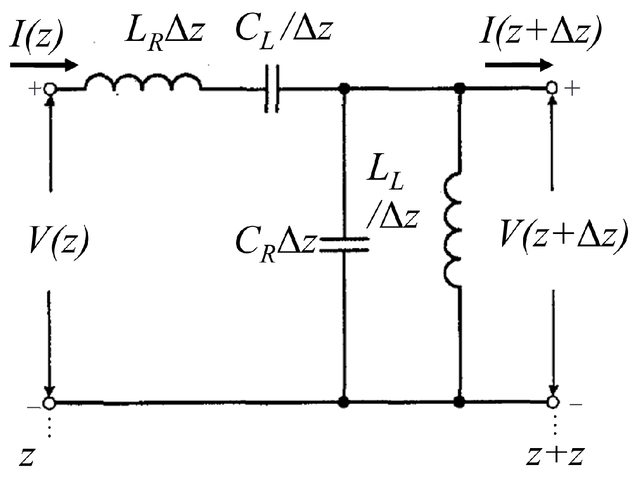
An ideal uniform CRLH transmission line equivalent circuit with distributed parameters is shown in Figure 1. Within a section of the CRLH transmission line, the series right-hand inductance per unit length is LR, the parallel right-hand capacitance per unit length is CR, the series left-hand capacitance per unit length is CL, and the parallel left-hand inductance per unit length is LL. Take a very small transmission line here, with a length of Δz, and, based on the series parallel relationship between capacitors and inductors, the values of distributed capacitance and inductance in this small section of transmission line can be obtained.

Figure 1.
The distributed parameters of the CRLH transmission line with a length of Δz.
According to Kirchhoff’s law of voltage
Dividing both sides of Equation (1) by Δz simultaneously, and when Δz approaches 0 infinitely, the differential equation can be obtained:
Let , , then the characteristics of CRLH transmission lines can be described by the following equations:
By further solving the Equations (5) and (6), the characteristic parameters on an ideal CRLH transmission line can be obtained. The series resonant frequency is defined as ωse, and the parallel resonant frequency is defined as ωsh
The pure left-handed impedance of a CRLH transmission line is ZL, and the pure right-handed impedance is ZR.
The characteristic impedance of the CRLH transmission line is as follows:
Let γ represent the propagation constant, and β represent the phase constant. As the transmission line is ideal and lossless, the attenuation constant is neglected.
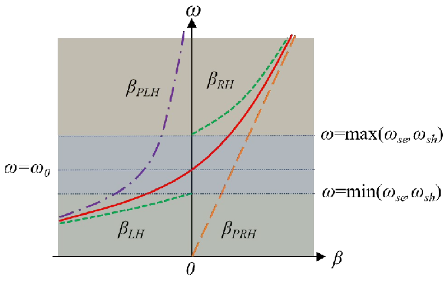
Figure 2 illustrates the dispersion curve of CRLH transmission line. βPLH represents the phase constant of the pure left-handed transmission line, where the phase constant is constantly less than 0 and, at this point, the phase velocity and group velocity are negative and positive respectively. βPRH represents the phase constant of the pure right-handed transmission line, where the phase constant is constantly greater than 0, and at this point the phase velocity and group velocity are both positive.
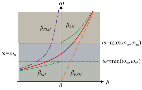
Figure 2.
Dispersion curve of transmission line.
In the unbalanced state, the dispersion curve of a CRLH transmission line is divided into two segments. When the operating frequency of the CRLH transmission line is lower than both the series resonant frequency ωse and the parallel resonant frequency ωsh (), it exhibits left-handed characteristics with a phase constant less than 0, i.e., the dispersion curve of βLH; When the operating frequency of the CRLH transmission line is greater than both the series resonance frequency ωse and the parallel resonance frequency ωsh , the phase constant is greater than 0, which is the dispersion curve of βRH. In this state, there is a bandgap in the transmission of waves in the CRLH transmission line.
Different from the unbalanced state, in the balanced state, where the series resonance frequency ωse and parallel resonance frequency ωsh are equal (ωse = ωsh), the dispersion curve of the composite left-handed and right-handed transmission lines is continuous, as shown by the red line in Figure 2. Assuming the balance frequency is the frequency where the series resonance frequency ωse and parallel resonance frequency ωsh are equal (ω0 = ωse = ωsh), the composite left-handed and right-handed transmission lines exhibit left-handed characteristics when the operating frequency is less than the balance frequency ω0. When the operating frequency is greater than the balance frequency ω0, the composite left-handed and right-handed transmission lines exhibit right-handed characteristics. In this state, waves can transmit through the composite left-handed and right-handed transmission lines across continuous frequency bands without any stopbands.
To further analyze the conditions necessary for the establishment of balanced state, given ωse = ωsh, it can be obtained from the Equations (7) and (8) that [22]
Then, combining Equations (9), (10) and (15), we can derive
Equation (16) reveals that, in a balanced state, the characteristic impedance of the CRLH transmission line is equal to the pure left-handed and pure right-handed impedances. This is in contrast to the frequency-dependent nature of the CRLH transmission line in an unbalanced state, where the characteristic impedance varies with frequency. In the balanced state, however, the characteristic impedance remains frequency-independent.
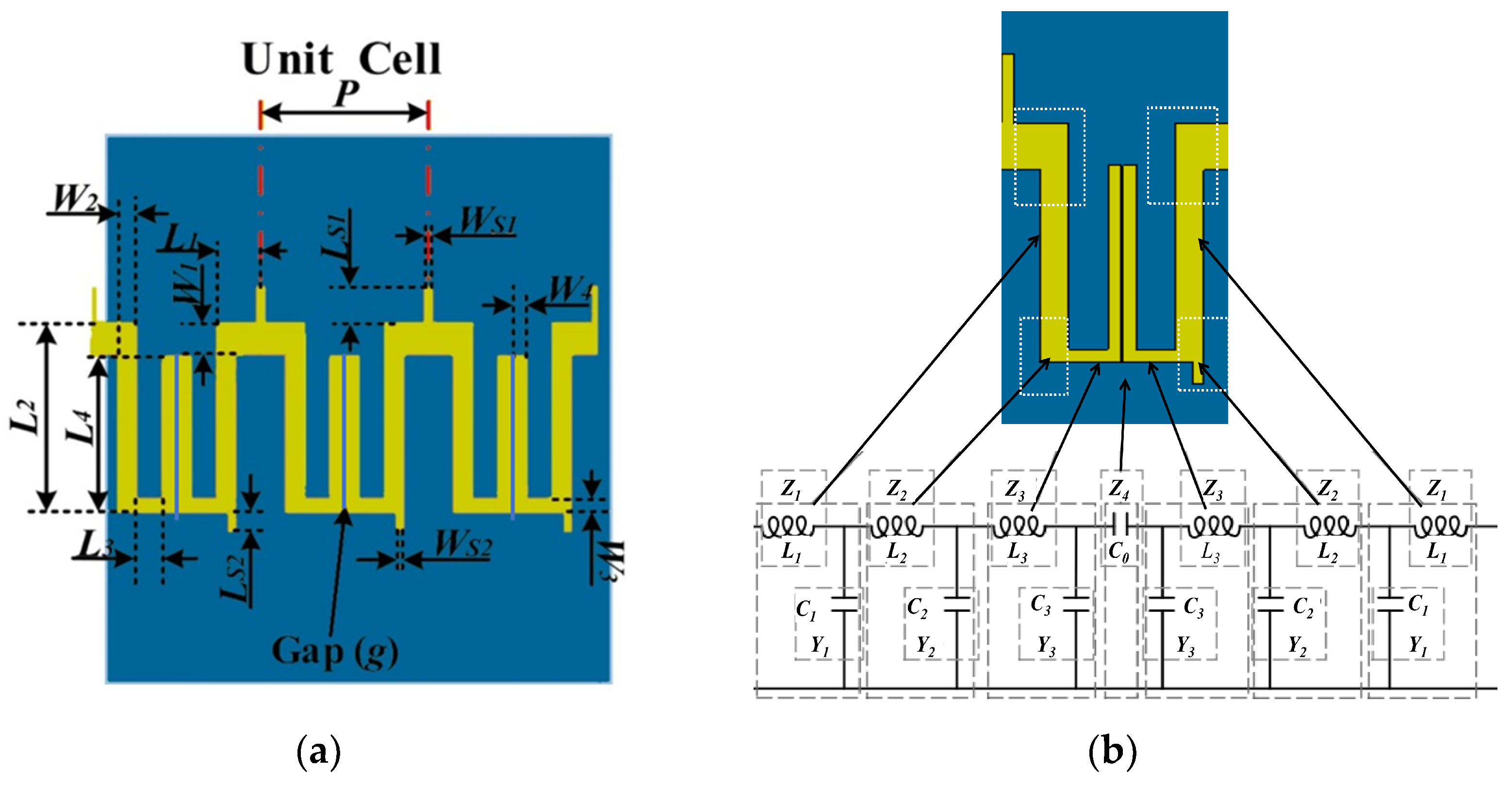
The antenna unit proposed in this study, illustrated in Figure 3, comprises two symmetrically curved microstrip lines with two short branches. A narrow gap between the curved microstrip lines acts as a capacitor, while the bent of the microstrip lines is equivalent to a capacitor and an inductor connected in parallel. This narrow gap is essential for forming the composite left-handed and right-handed transmission lines within the transmission line structure. By adjusting the narrow gap, the Q factor of the unit cell can be modified. Additionally, the two short branches contribute to improved impedance matching.

Figure 3.
The proposed antenna unit. (a) Dimension of the antenna unit; (b) equivalent circuit of antenna unit.
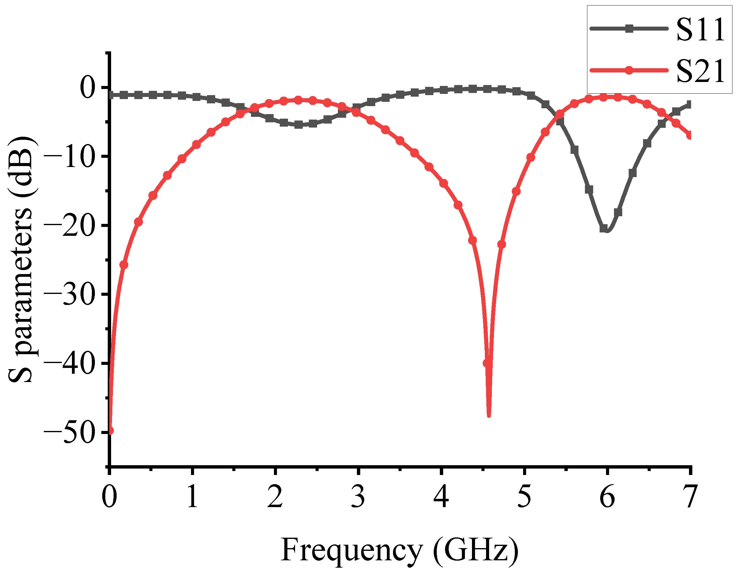
To begin, the electromagnetic simulation software CST Microwave Studio 2023 is employed to analyze the operating mode of the antenna unit, where the S-parameters are obtained and depicted in Figure 4.
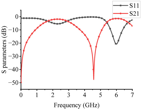
Figure 4.
The Sparameter of the proposed antenna unit.
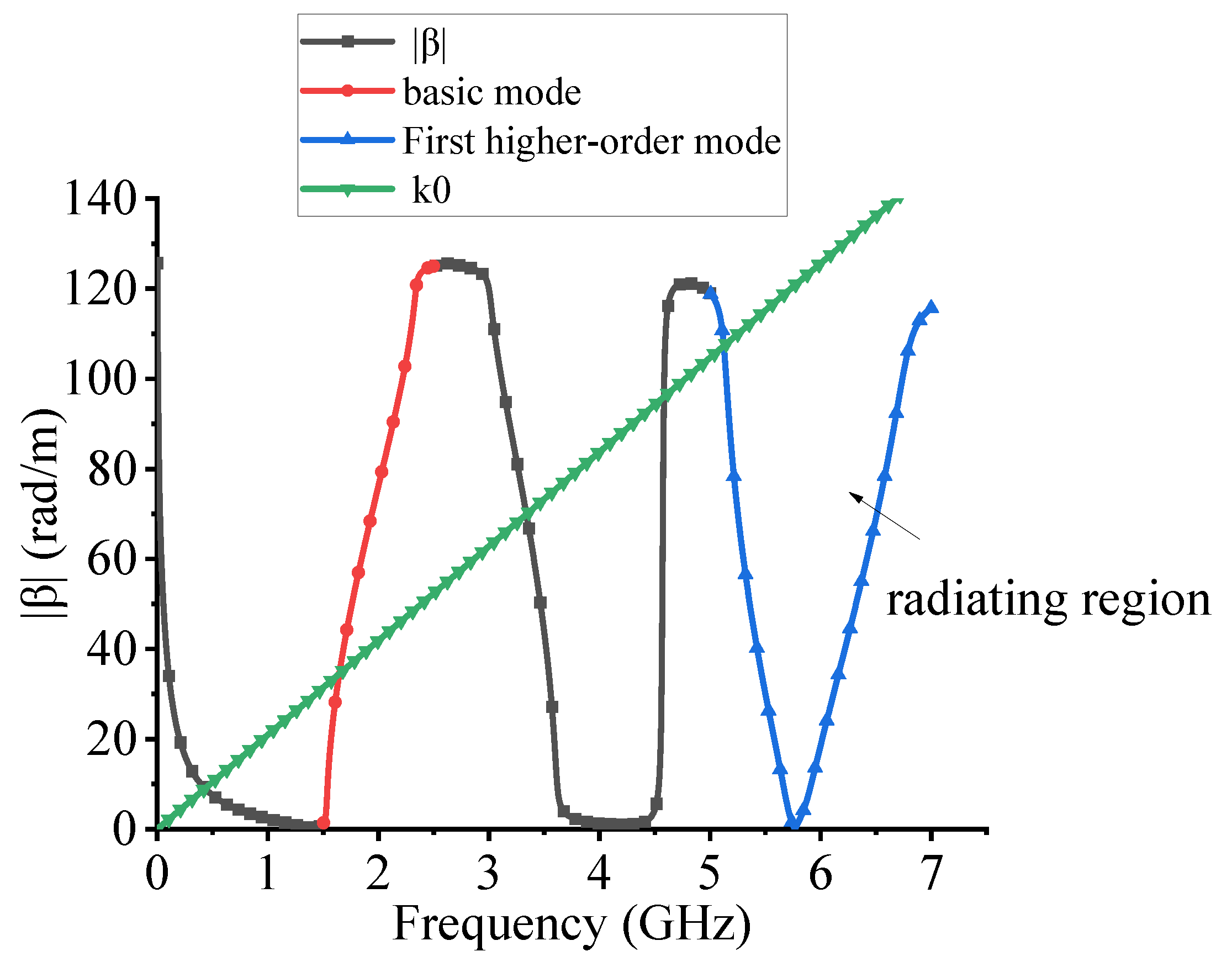
Utilizing the relationships between the transmission matrix and the S-parameter [23], as well as between the transmission matrix and the transmission constant [24], as presented in Equations (17)–(19), we derive the relationship between the magnitude of the phase constant and the S-parameters for lossy CRLH-TL in Equation (20). Figure 5 graphically illustrates this relationship.
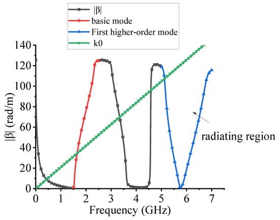
Figure 5.
Dispersion curve of the proposed antenna unit.
For the antenna unit to effectively radiate electromagnetic waves, it must operate in the fast wave mode, characterized by the absolute value of the phase constant being less than the wavenumber in free space (|β| < k0). This condition is fulfilled in the region below the green line in the lower right corner of Figure 5, indicating that the antenna unit operates in the fast wave mode when functioning in the second mode, thus satisfying the requirements for electromagnetic wave radiation.
Figure 5 reveals that the center frequency of the first mode of the antenna unit is 2 GHz, while the center frequency of the second mode is 6 GHz. The transmission characteristics in the first mode are suboptimal, with a maximum return loss of only 5 dB. Conversely, in the second mode, the return loss reaches up to 20 dB, indicating superior transmission properties favorable for cascading multiple units to form an array antenna.
By examining the dispersion plot, we can ascertain the group and phase velocities of the antenna unit, thereby determining whether the unit exhibits left-handed or right-handed characteristics. Figure 5 shows that the dispersion characteristics of the first mode indicate right-handed properties, while the second mode exhibits left-handed characteristics below 5.7 GHz and right-handed characteristics above this frequency. Additionally, the antenna unit achieves a balance between composite left-handed and right-handed transmission lines, facilitating wave transmission across continuous frequency bands without stopbands.
In summary, when operating in the second mode, based on the composite left-handed and right-handed transmission lines, the antenna unit demonstrates excellent transmission characteristics and maintains a balance between the two transmission modes. It also satisfies the conditions necessary for electromagnetic wave radiation, making it suitable for use in frequency-scanning antennas formed by cascading antenna units.
In this section, the characteristic parameters of CRLH-TL are initially presented. Subsequently, based on the dispersion curve, we discuss the unbalanced state, balanced state, and balanced condition of CRLH-TL. Thirdly, an antenna unit based on CRLH-TL (Composite Right/Left-Handed Transmission Line) is proposed, highlighting the significant impact of the narrow gap and two short branches on its transmission characteristics. Finally, the S-parameter and dispersion curve of the antenna unit are obtained, confirming that the second mode is an optimal operating mode.
3. Simulation Results
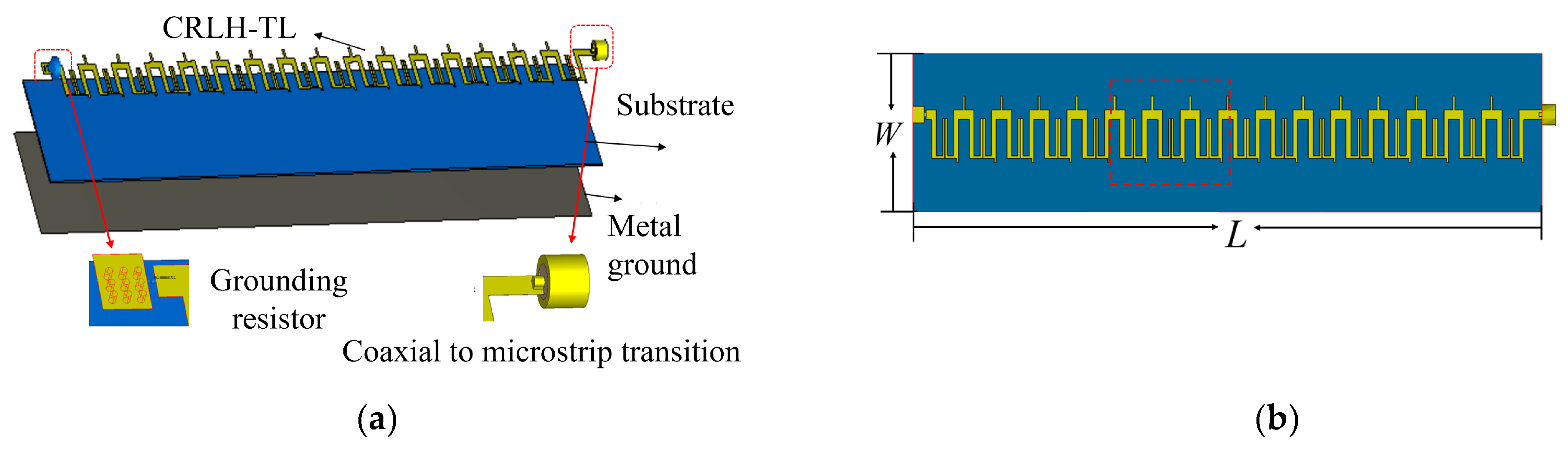
Based on the design of the antenna unit in the previous section, here 16 antenna units are cascaded. The overall topology of the antenna is shown in Figure 6. This employs a microstrip structure composed of three tightly pressed layers. The top layer features a metal microstrip structure with a thickness of 0.035 mm. The middle layer consists of an AD300C substrate (Rogers Co., Chandler, AZ, USA), characterized by a dielectric constant of 2.98, a loss tangent of 0.0014, and a thickness of 0.762 mm. The bottom layer serves as a metal ground. The antenna is fed electromagnetic energy through a coaxial input port that utilizes the classic coaxial-to-microstrip conversion structure.

Figure 6.
The LWA antenna prototype. (a) Stacked diagram; (b) Top view.
To ensure the antenna operates in a traveling wave state, a 0603 packaged resistor with a resistance value of 50 Ω is soldered onto a slot with a width of 0.6 mm, serving as an absorbing load at the end of the antenna. This configuration involves the ground plane on the slot’s left side and the microstrip antenna on the right. The incorporation of the resistor, alongside the tuning of the narrow gap and two short branches, as well as the optimization of other parameters, results in an antenna with overall dimensions smaller than the coaxial load on the right end. These dimensions are detailed in Table 1.

Table 1.
Dimensions of the proposed antenna (Unit: mm).
The optimized simulation results are shown in Figure 7. It can be seen from Figure 7 that the antenna has a return loss greater than 10 dB (S11 < −10 dB) in the frequency range of 5.5–6.5 GHz, with a center frequency of 6 GHz and a relative bandwidth of 16.7%.
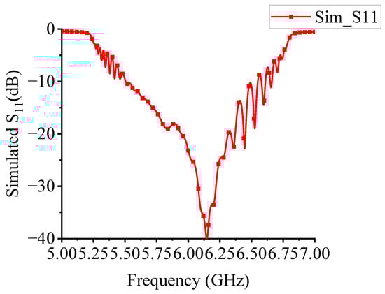
Figure 7.
The simulated S parameter of the proposed antenna.
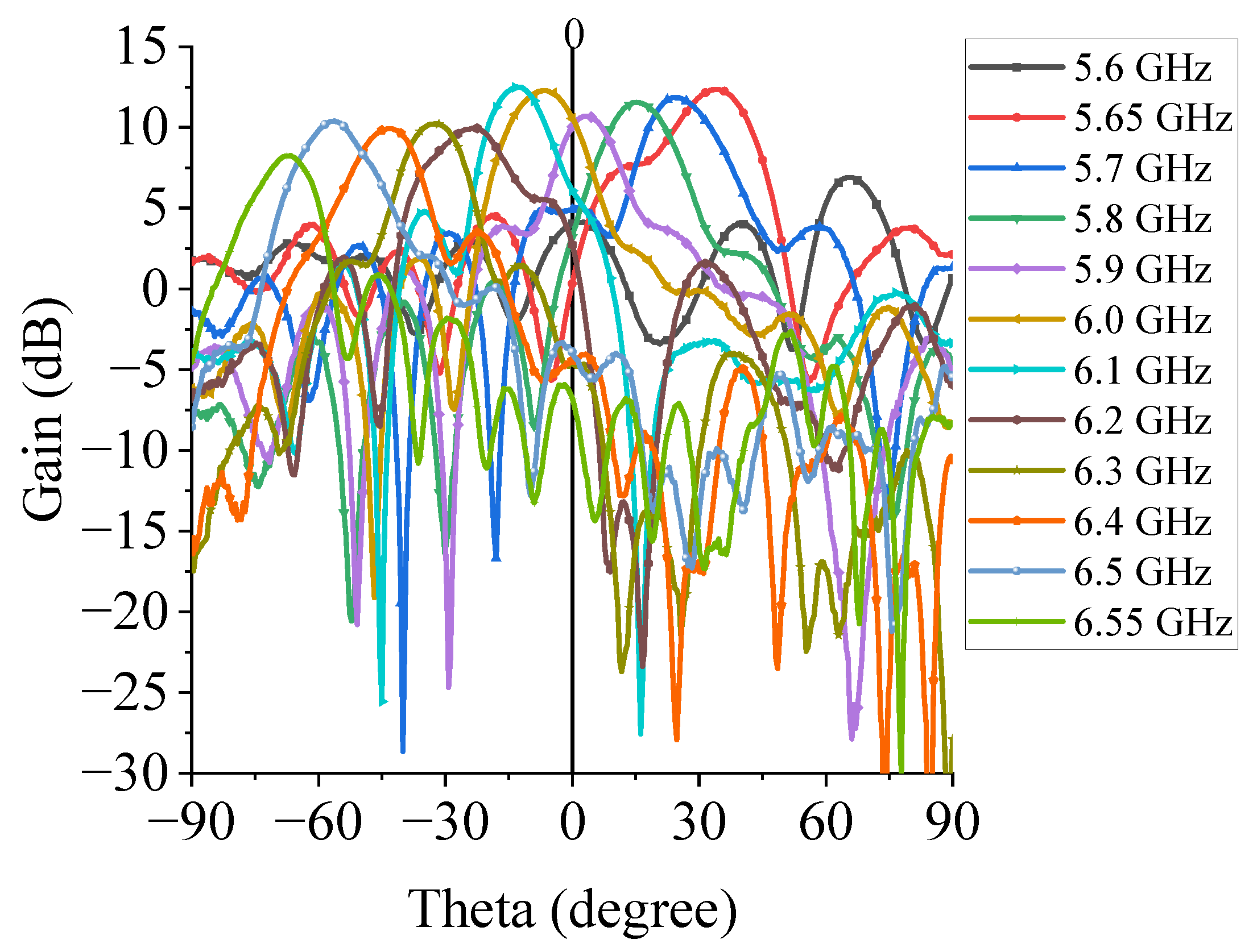
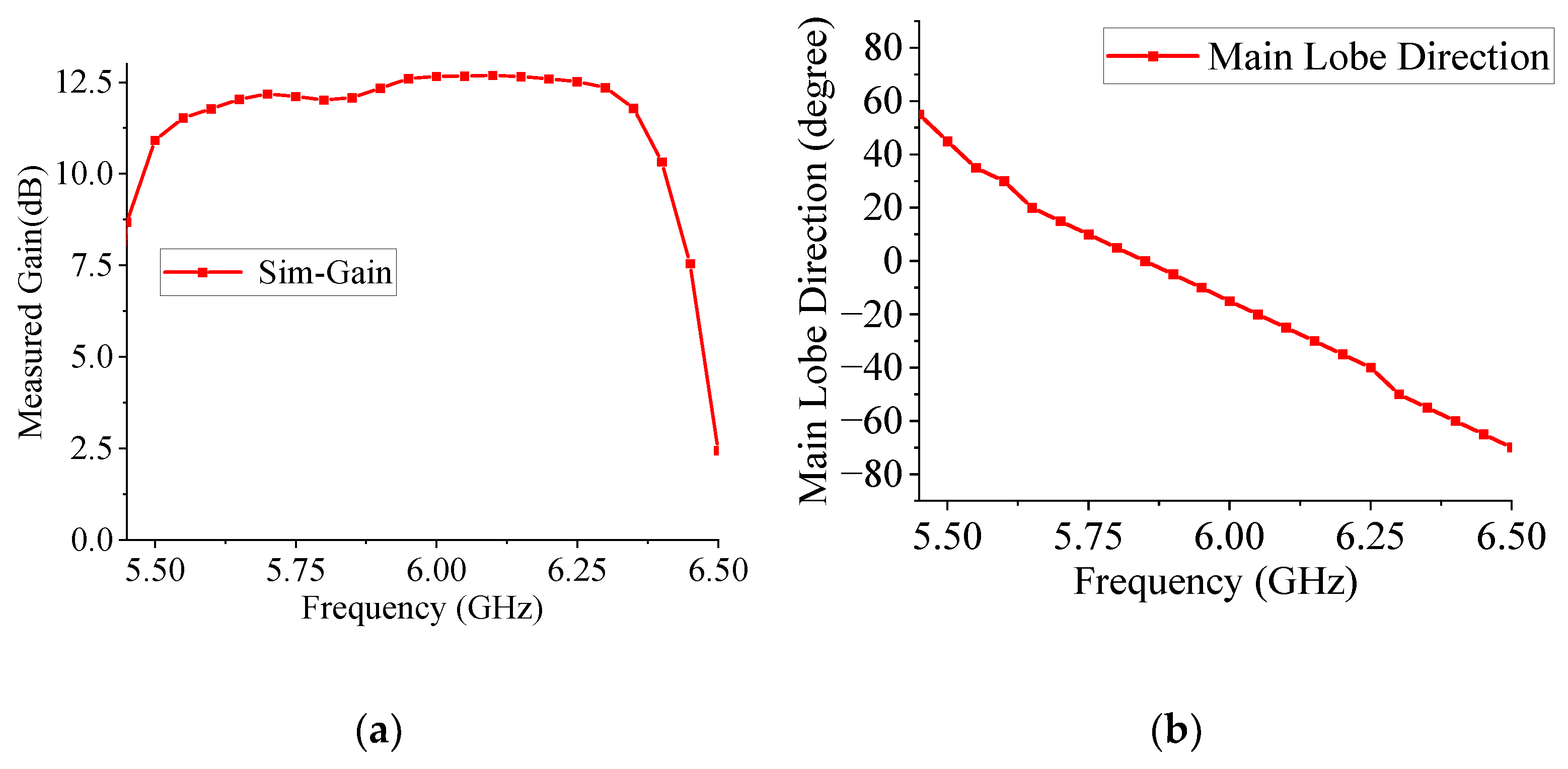
The radiation pattern is shown in Figure 8. This antenna can achieve continuous beam scanning within the frequency range of 5.5 GHz to 6.4 GHz. At 5.5 GHz, the scanning angle is +50°, and at 6.4 GHz, the scanning angle is −60°. Figure 9 displays the gain and scanning angles at different frequencies. Within the 5.5 GHz to 6.5 GHz frequency range, the maximum gain is 12.68 dBi, the minimum gain is 10.26 dBi, and the gain variation within the band is less than 2.43 dB.
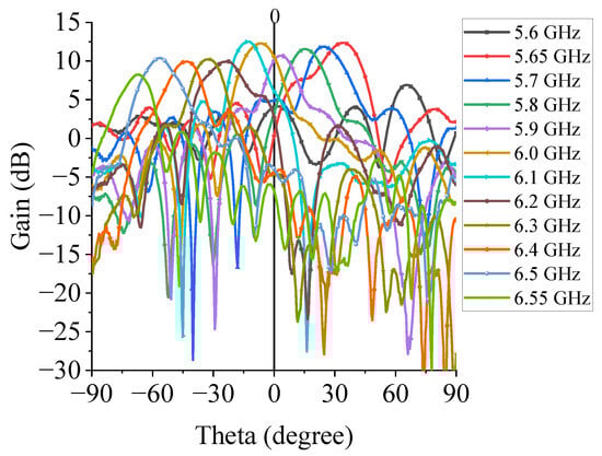
Figure 8.
The horizontal (H-plane) radiation pattern at different frequencies.
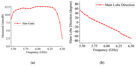
Figure 9.
Antenna scanning performance at different frequencies. (a) Antenna gain at different frequencies. (b) Antenna scanning angles at different frequencies.
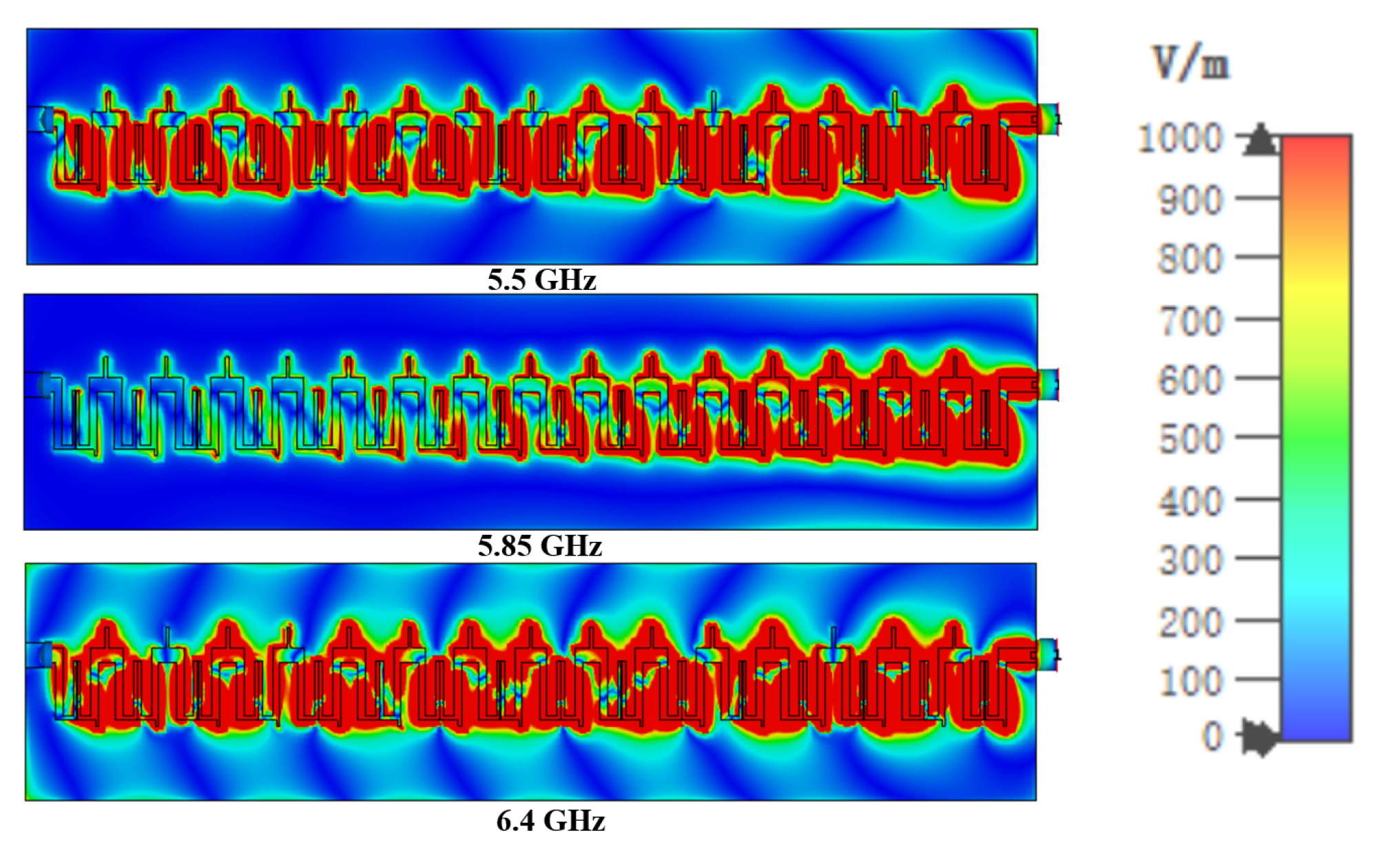
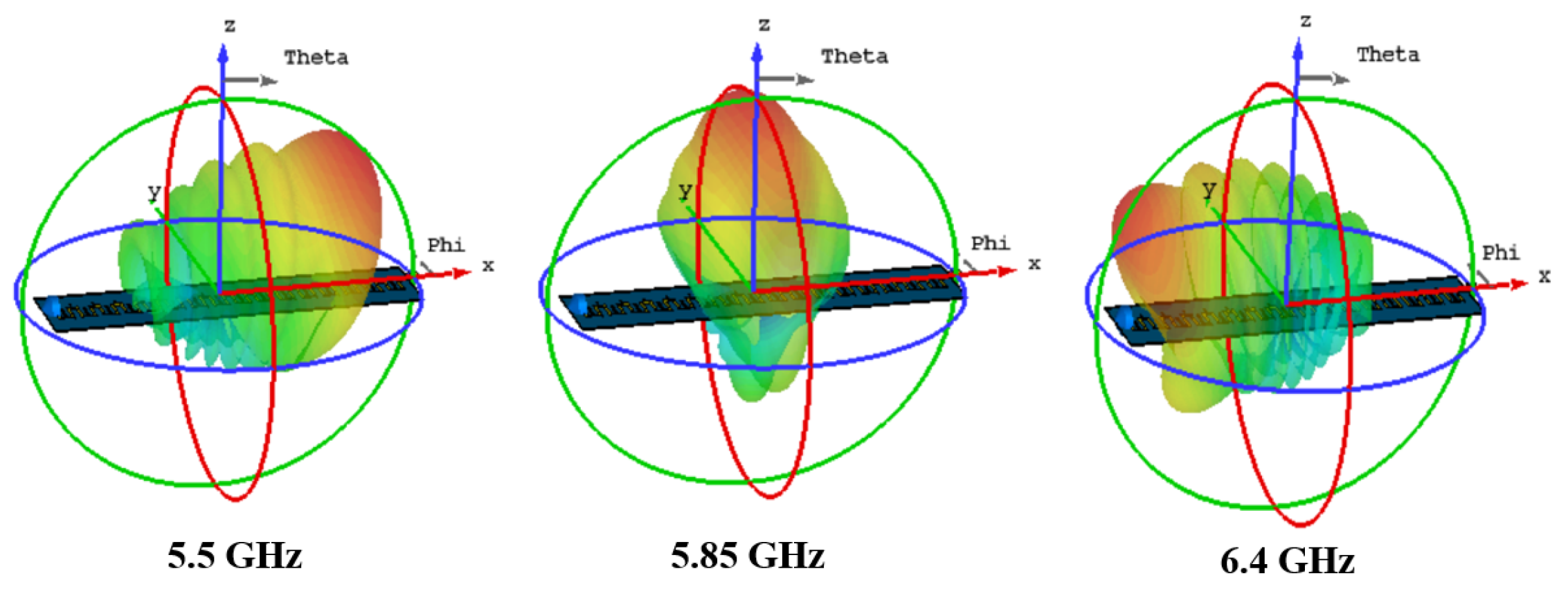
To provide a clearer description of the antenna radiation characteristics, electric field distribution diagrams and the antenna’s 3D radiation pattern at different frequency points are provided, as shown in Figure 10 and Figure 11. At low frequencies, the CRLH transmission lines exhibit left-hand characteristics, resulting in backward radiation from the scanning antenna; at the balance point, the CRLH transmission lines of the scanning antenna produce side radiation; at high frequencies, the CRLH transmission lines exhibit right-hand characteristics, leading to forward radiation from the scanning antenna.
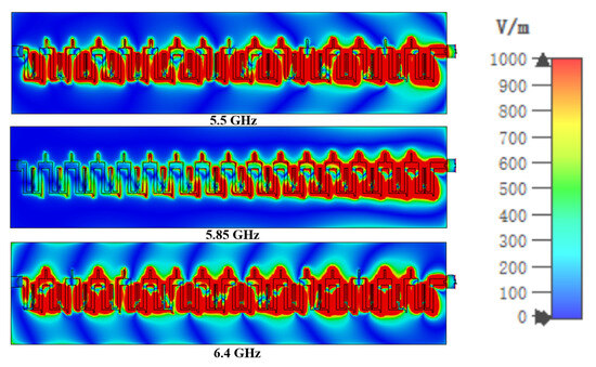
Figure 10.
The electric field distribution of the antenna at the frequencies of 5.5 GHz, 5.85 GHz and 6.4 GHz.
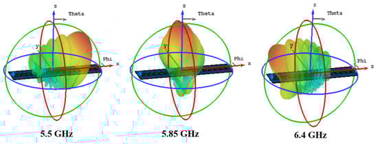
Figure 11.
3D radiation pattern of antenna at 5.5 GHz, 5.85 GHz, and 6.4 GHz frequencies.
4. Experiments
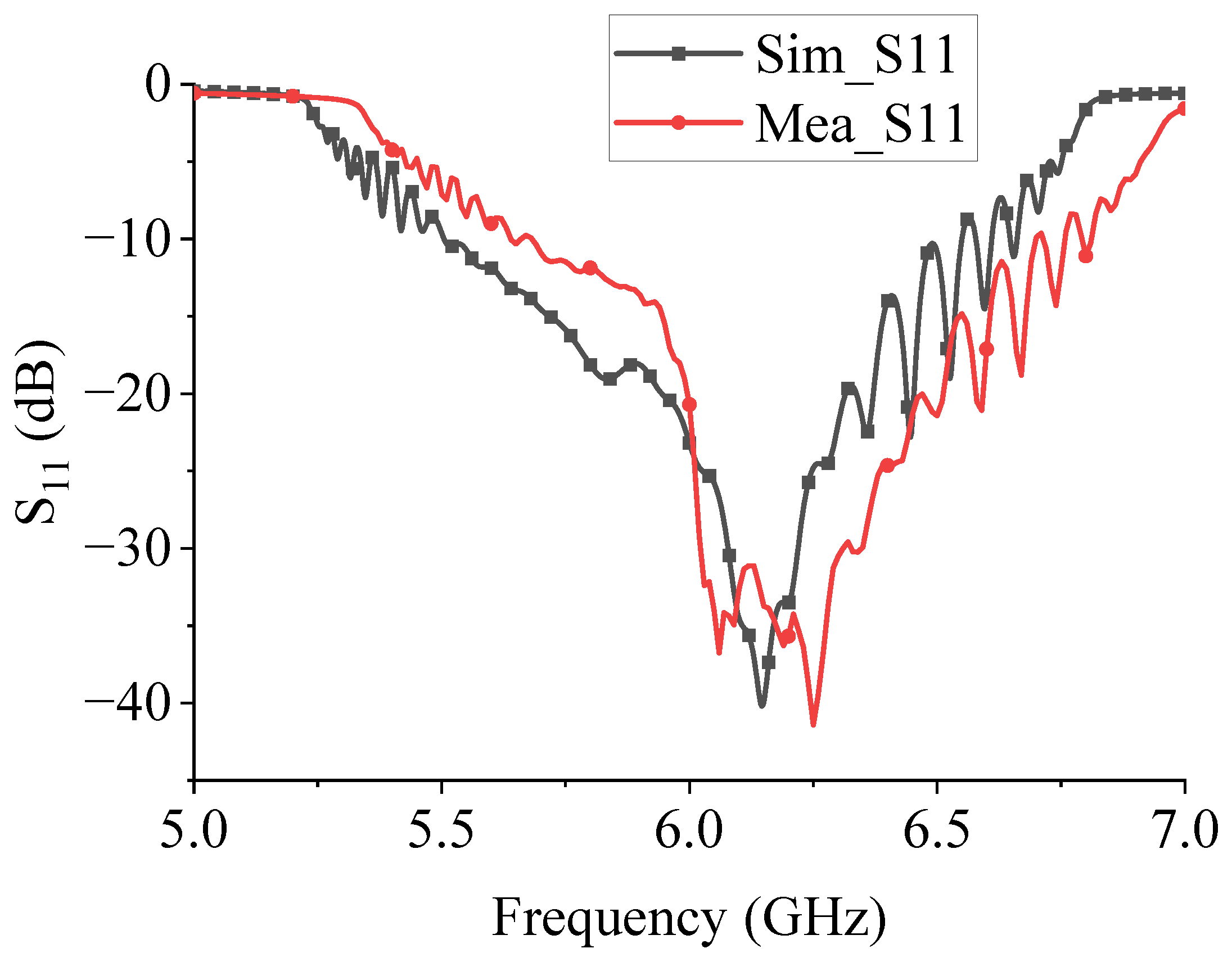
The antenna object and its S-parameters are tested using the vector Network analyzer Agilent N5244A (Agilent Co., Santa Clara, CA, USA) as shown in Figure 12. Figure 13 shows the comparison between the S-parameter test curve and the simulation curve. It can be seen that the working frequency of the antenna moves to high frequency by about 0.1 GHz, which is caused by machining error.
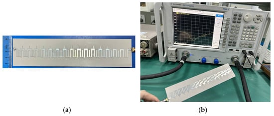
Figure 12.
Fabricated antenna and testing scenario. (a) Top view; (b) S-parameter testing scenario.

Figure 13.
Simulation and test results of antenna S parameters.
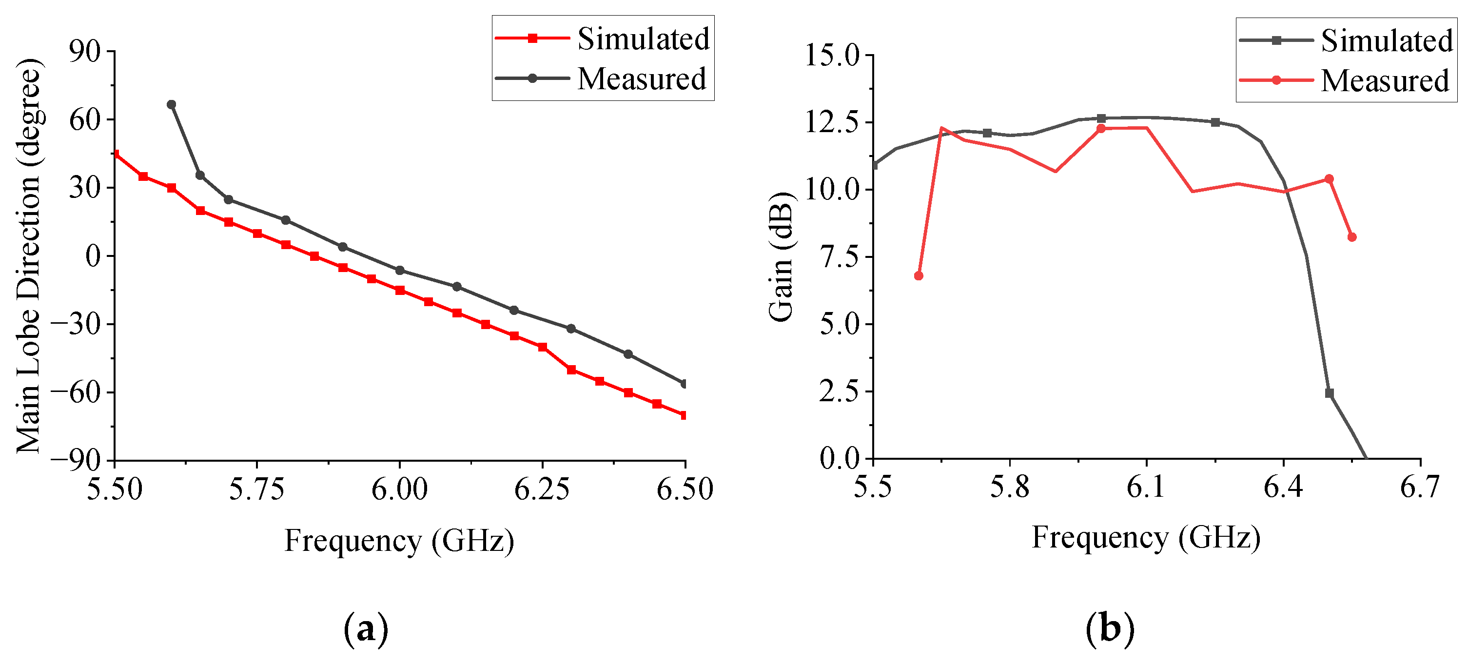
Figure 14 illustrates the antenna pattern measurement setup, utilizing a Rohde and Schwarz ZVA40 vector network analyzer (Rohde & Schwarz Co., Munich, Germany). The H-plane radiation patterns at selected frequencies are presented in Figure 15, demonstrating consistent beam steering behavior across the operating band. Figure 16 compares the simulated and measured gain versus scanning angle, revealing excellent agreement between the two datasets.
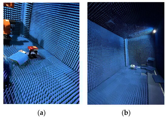
Figure 14.
The measurement set-up in an anechoic chamber. (a) Antenna under test; (b) Standard horn antenna.
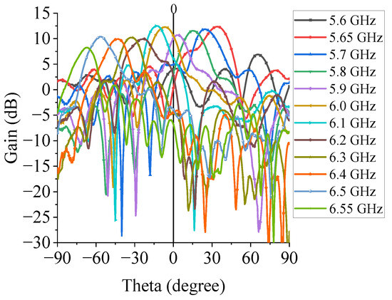
Figure 15.
H-plane radiation pattern at different frequencies tested.
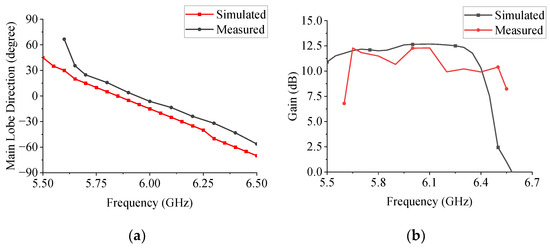
Figure 16.
Simulation and test results of gain and scanning angle antennas at different frequencies. (a) Scanning angle (b) Gain.
The proposed antenna achieves a continuous scanning range of 103° (from +35.5° to −67.5°) over the frequency band of 5.65–6.5 GHz, with a gain variation of less than 2 dB (10–12.3 dBi). This performance combination—wide angular coverage, stable gain, and high scanning rate—represents a significant improvement over existing designs, as quantitatively compared in Table 2. Specifically, our design outperforms recent LWAs with similar structures in both scanning linearity and gain flatness, making it a promising candidate for frequency-scanning applications requiring robust beam steering capabilities.
Table 2.
Comparison of Different High-Scanning-Rate LWAs.
5. Conclusions
In this paper, a novel CRLH unit cell is developed to design a high-scanning-rate LWA. A narrow gap and two branches of this unit cell are utilized respectively to tune the Q factor and improve impedance matching. Dispersion characteristics and operating mode of this unit cell are analyzed. Finally, An LWA prototype with 16 proposed unit cells is designed, fabricated, and measured. The measured results prove that the antenna can obtain a continuous scanning range from −67.5° to +35.5° over the frequency range of 5.65 to 6.5 GHz with relatively flat gain (10–12.3 dBi). Given its high scanning rate, stable gain, compact structure, and ease of fabrication, the proposed LWA presents a promising candidate for microwave sensing and wireless communication applications.
Author Contributions
Investigation, Z.H.; Writing—review and editing, Z.H.; Conceptualization, K.S.; methodology, K.S.; validation, Y.Z.; writing—original draft preparation, J.Y.; funding acquisition, K.S. All authors have read and agreed to the published version of the manuscript.
Funding
The work for this grant was supported in part by National Natural Science Foundation of China (Grant No: 62171097) and by the Natural Science Foundation of Sichuan Province of China (Grant No: 2024NSFSC0463) (Corresponding author: Kaijun Song).
Data Availability Statement
Due to privacy and ethical considerations, the dataset cannot be made publicly accessible.
Conflicts of Interest
The authors declare no conflicts of interest.
References
- Yan, N.; Ma, K.; Zhang, H.; Jian, Z. A Novel Substrate Integrated Suspended Line Wideband Leaky-Wave Antenna. IEEE Antennas Wirel. Propag. Lett. 2017, 16, 2642–2645. [Google Scholar] [CrossRef]
- Zheng, D.; Lyu, Y.-L.; Wu, K. Transversely Slotted SIW Leaky-Wave Antenna Featuring Rapid Beam-Scanning for Millimeter-Wave Applications. IEEE Trans. Antennas Propag. 2020, 68, 4172–4185. [Google Scholar] [CrossRef]
- Zheng, D.; Wu, K. Multifunctional Filtering Leaky-Wave Antenna Exhibiting Simultaneous Rapid Beam-Scanning and Frequency-Selective Characteristics Based on Radiative Bandpass Filter Concept. IEEE Trans. Antennas Propag. 2020, 68, 5842–5854. [Google Scholar] [CrossRef]
- Caloz, C.; Sanada, A.; Itoh, T. A novel composite right-/left-handed coupled-line directional coupler with arbitrary coupling level and broad bandwidth. IEEE Trans. Microw. Theory Tech. 2004, 52, 980–992. [Google Scholar] [CrossRef]
- Lin, X.Q.; Ma, H.F.; Bao, D.; Cui, T.J. Design and Analysis of Super-Wide Bandpass Filters Using a Novel Compact Meta-Structure. IEEE Trans. Microw. Theory Tech. 2007, 55, 747–753. [Google Scholar] [CrossRef]
- Mao, S.-G.; Chueh, Y.-Z. Broadband composite right/left-handed coplanar waveguide power splitters with arbitrary phase responses and balun and antenna applications. IEEE Trans. Antennas Propag. 2006, 54, 243–250. [Google Scholar] [CrossRef]
- Hirota, A.; Tahara, Y.; Yoneda, N. A Compact Forward Coupler Using Coupled Composite Right/Left-Handed Transmission Lines. IEEE Trans. Microw. Theory Tech. 2009, 57, 3127–3133. [Google Scholar] [CrossRef]
- Lee, J.-Y.; Kim, D.-J.; Park, B.-C.; Lee, J.-H. High order bandpass filter using the first negative resonant mode of composite right/left-handed transmission line. In Proceedings of the 2008 IEEE Antennas and Propagation Society International Symposium, San Diego, CA, USA, 5–11 July 2008; pp. 1–4. [Google Scholar] [CrossRef]
- Buell, K.; Mosallaei, H.; Sarabandi, K. A substrate for small patch antennas providing tunable miniaturization factors. IEEE Trans. Microw. Theory Tech. 2006, 54, 135–146. [Google Scholar] [CrossRef]
- Ji, J.; Kim, G.; Seong, W. A Compact Multiband Antenna Based on CRLH-TL ZOR for Wireless Mobile System. Microwave and Optical Technology Letters. 2009. Available online: https://www.semanticscholar.org/paper/A-compact-multiband-antenna-based-on-CRLH%E2%80%90TL-ZOR-Ji-Kim/9490cb043a8af5988d6ce6960898450ede24c31f (accessed on 21 December 2024).
- Ryu, Y.; Park, J.; Lee, J.; Tae, H. Multiband antenna using +1, −1, and 0 resonant mode of DGS dual composite right/left handed transmission line. Micro Opt. Tech Lett. 2009, 51, 2485–2488. [Google Scholar] [CrossRef]
- Jin, C.; Alphones, A.; Ong, L.C. Broadband leaky-wave antenna based on composite right/left handed substrate integrated waveguide. Electron. Lett. 2010, 46, 1584–1585. [Google Scholar] [CrossRef]
- Jin, C.; Alphones, A. Leaky-Wave Radiation Behavior From a Double Periodic Composite Right/Left-Handed Substrate Integrated Waveguide. IEEE Trans. Antennas Propag. 2012, 60, 1727–1735. [Google Scholar] [CrossRef]
- Lyu, Y.-L.; Liu, X.-X.; Wang, P.-Y.; Erni, D.; Wu, Q.; Wang, C.; Kim, N.-Y.; Meng, F.-Y. Leaky-Wave Antennas Based on Noncutoff Substrate Integrated Waveguide Supporting Beam Scanning From Backward to Forward. IEEE Trans. Antennas Propag. 2016, 64, 2155–2164. [Google Scholar] [CrossRef]
- Alibakhshikenari, M.; Virdee, B.S.; Khalily, M.; Shukla, P.; See, C.H.; Abd-Alhameed, R.; Falcone, F.; Limiti, E. Beam-scanning leaky-wave antenna based on CRLH-metamaterial for millimetre-wave applications. IET Microw. Antennas Propag. 2019, 13, 1129–1133. [Google Scholar] [CrossRef]
- Sarkar, A.; Adhikary, M.; Sharma, A.; Biswas, A.; Akhtar, M.J.; Hu, Z. Composite right/left-handed based compact and high gain leaky-wave antenna using complementary spiral resonator on HMSIW for Ku band applications. IET Microw. Antennas Propag. 2018, 12, 1310–1315. [Google Scholar] [CrossRef]
- Karmokar, D.K.; Chen, S.-L.; Bird, T.S.; Guo, Y.J. Single-Layer Multi-Via Loaded CRLH Leaky-Wave Antennas for Wide-Angle Beam Scanning With Consistent Gain. IEEE Antennas Wirel. Propag. Lett. 2019, 18, 313–317. [Google Scholar] [CrossRef]
- Chen, S.-L.; Karmokar, D.K.; Li, Z.; Qin, P.-Y.; Ziolkowski, R.W.; Guo, Y.J. Continuous Beam Scanning at a Fixed Frequency With a Composite Right-/Left-Handed Leaky-Wave Antenna Operating Over a Wide Frequency Band. IEEE Trans. Antennas Propag. 2019, 67, 7272–7284. [Google Scholar] [CrossRef]
- Sarkar, A.; Pham, D.A.; Lim, S. Tunable Higher Order Mode-Based Dual-Beam CRLH Microstrip Leaky-Wave Antenna for V-Band Backward–Broadside–Forward Radiation Coverage. IEEE Trans. Antennas Propag. 2020, 68, 6912–6922. [Google Scholar] [CrossRef]
- Karmokar, D.K.; Guo, Y.J.; Chen, S.-L.; Bird, T.S. Composite Right/Left-Handed Leaky-Wave Antennas for Wide-Angle Beam Scanning With Flexibly Chosen Frequency Range. IEEE Trans. Antennas Propag. 2020, 68, 100–110. [Google Scholar] [CrossRef]
- Yang, W.; Peng, Z.; Ren, J.; Gao, J.; Zhai, G. Composite Right/Left-Handed Leaky-Wave Antenna With High Scanning Rate. IEEE Antennas Wirel. Propag. Lett. 2022, 21, 2522–2526. [Google Scholar] [CrossRef]
- Eleftheriades, G.V.; Iyer, A.K.; Kremer, P.C. Planar negative refractive index media using periodically L-C loaded transmission lines. IEEE Trans. Microw. Theory Techn. 2002, 50, 2702–2712. [Google Scholar]
- Pozar, D.M. Microwave Engineering; Wiley: New York, NY, USA, 2005. [Google Scholar]
- Kuchment, P.A. Floquet Theory for Partial Differential Equations; Birkhäuser: Basel, Switzerland, 2012; Volume 60. [Google Scholar]
- Zhou, W.; Liu, J.; Long, Y. Investigation of Shorting Vias for Suppressing the Open Stopband in an SIW Periodic Leaky-Wave Structure. IEEE Trans. Microw. Theory Tech. 2018, 66, 2936–2945. [Google Scholar] [CrossRef]
- Ma, D.; Zhong, J.; Shen, S.; Dubey, A.; Zhang, C.; Zhang, Q.; Murch, R. Single-Shot Frequency-Diverse Near-Field Imaging Using High-Scanning-Rate Leaky-Wave Antenna. IEEE Trans. Microw. Theory Tech. 2021, 69, 3399–3412. [Google Scholar] [CrossRef]
- Guan, D.-F.; Zhang, Q.; You, P.; Yang, Z.-B.; Zhou, Y.; Yong, S.-W. Scanning Rate Enhancement of Leaky-Wave Antennas Using Slow-Wave Substrate Integrated Waveguide Structure. IEEE Trans. Antennas Propag. 2018, 66, 3747–3751. [Google Scholar] [CrossRef]
- Zhang, G.; Zhang, Q.; Ge, S.; Chen, Y.; Murch, R.D. High Scanning-Rate Leaky-Wave Antenna Using Complementary Microstrip-Slot Stubs. IEEE Trans. Antennas Propag. 2019, 67, 2913–2922. [Google Scholar] [CrossRef]
- Xie, D.; Zhu, L. Microstrip Leaky-Wave Antennas With Nonuniform Periodical Loading of Shorting Pins for Enhanced Frequency Sensitivity. IEEE Trans. Antennas Propag. 2018, 66, 3337–3345. [Google Scholar] [CrossRef]
- Garcia-Vigueras, M.; Gomez-Tornero, J.L.; Goussetis, G.; Weily, A.R.; Guo, Y.J. Enhancing Frequency-Scanning Response of Leaky-Wave Antennas Using High-Impedance Surfaces. IEEE Antennas Wirel. Propag. Lett. 2011, 10, 7–10. [Google Scholar] [CrossRef]


Disclaimer/Publisher’s Note: The statements, opinions and data contained in all publications are solely those of the individual author(s) and contributor(s) and not of MDPI and/or the editor(s). MDPI and/or the editor(s) disclaim responsibility for any injury to people or property resulting from any ideas, methods, instructions or products referred to in the content. |
© 2025 by the authors. Licensee MDPI, Basel, Switzerland. This article is an open access article distributed under the terms and conditions of the Creative Commons Attribution (CC BY) license (https://creativecommons.org/licenses/by/4.0/).