Article

Alleviating the Communication Bottleneck in Neuromorphic Computing with Custom-Designed Spiking Neural Networks

1
Department of Electrical Engineering and Computer Science, University of Tennessee, 401 Min Kao Building, Knoxville, TN 37996, USA
2
Arete, Inc., Huntsville, AL 35801, USA
*
Author to whom correspondence should be addressed.
J. Low Power Electron. Appl. 2025, 15(3), 50; https://doi.org/10.3390/jlpea15030050
Submission received: 23 July 2025 / Revised: 26 August 2025 / Accepted: 28 August 2025 / Published: 8 September 2025
(This article belongs to the Special Issue Neuromorphic Computing for Edge Applications)

Abstract

For most, if not all, AI-accelerated hardware, communication with the agent is expensive and heavily bottlenecks the hardware performance. This omnipresent hardware restriction is also found in neuromorphic computing: a novel style of computing that involves deploying spiking neural networks to specialized hardware to achieve low size, weight, and power (SWaP) compute. In neuromorphic computing, spike trains, times, and values are used to communicate information to, from, and within the spiking neural network. Input data, in order to be presented to a spiking neural network, must first be encoded as spikes. After processing the data, spikes are communicated by the network that represent some classification or decision that must be processed by decoder logic. In this paper, we first present principles for interconverting between spike trains, times, and values using custom-designed spiking subnetworks. Specifically, we present seven networks that encompass the 15 conversion scenarios between these encodings. We then perform three case studies where we either custom design a novel network or augment existing neural networks with these conversion subnetworks to vastly improve their communication performance with the outside world. We employ a classic space vs. time tradeoff by pushing spike data encoding and decoding techniques into the network mesh (increasing space) in order to minimize intra- and extranetwork communication time. This results in a classification inference speedup of 23× and a control inference speedup of 4.3× on field-programmable gate array hardware.

1. Introduction

Neuromorphic computing offers the opportunity for highly performant intelligent computation with low size, weight, and power [1,2]. Because there is no central memory or common bus and because of their event-driven computation, hardware implementations of neuromorphic processors (“neuroprocessors”) can achieve very low power. Multiple hardware projects have targeted neuroprocessors for applications such as robotics, on-sensor processing, or wearables, where intelligent processing is required, but there are significant constraints with respect to size, weight, and power [3,4,5].
Neuroprocessors process spiking neural networks (SNNs). These networks are composed of neurons that store activation potentials and synapses that communicate spikes temporally from neuron to neuron. Because of their simplicity, neuroprocessors process neural networks with exceptionally high speed and low power [2,6], promising to meet the latency requirements of real-world applications. Two major challenges with SNNs, that spur research in the field, are designing or training them to perform specific tasks and communicating with them efficiently.
Two distinct ways of designing SNNs are to employ machine learning and to custom-design them by hand. In both cases, information must be communicated from the outside world to the SNN, and in doing so, the information must be converted into the primitives supported by the neuroprocessor. Specifically, the information may be communicated as spikes that are applied to input neurons or as values that get added to the neurons’ action potentials. Similarly, information must be obtained from the SNN to the outside world. This is typically effected by communicating spike events—their number and their timing—from designated output neurons.
Communicating with neuroprocessors efficiently is both an algorithmic challenge (as discussed above) and a hardware challenge (how to communicate data to/from the neuroprocessor itself). A key challenge with accelerators in general (not just neuromorphic) is the potential for a communication bottleneck, wherein the time required to communicate data to and from the accelerator can outweigh any speed benefit from the accelerator itself. Different communication technologies can be used to improve latency, but often, higher-performing communication schemes require significantly more power, which again may defeat the purpose of using a lower power accelerator. Thus, alleviating the communication bottleneck in order to achieve lower latency and low power for real-time neuromorphic deployments is paramount to their success.
In this paper, we consider three common methods of communicating and storing information within SNNs. These are to use spike times, spike trains, or the values stored in action potentials. These methods are used for different reasons, including ease of training, mathematical properties, and communication efficiency. We demonstrate how to convert each of these methods to the other by using a small, custom-designed SNN. We present each conversion network precisely and list its properties.
We then describe three case studies to highlight the effectiveness of using these techniques to design SNNs that can be efficiently deployed to hardware for applications that require real-time communication. In the first case study, we use the techniques to develop an SNN that compares the spiking activity of two output neurons, and emits a single spike to indicate the neuron that spikes the most. This effectively implements a “Winner-take-all” decoder as a communication-efficient SNN.
In the second case study, we consider a classification application, whose training via machine learning can best leverage spike trains for both input encoding and output decoding. When implemented on hardware, in our case on a field-programmable gate array (FPGA), these techniques perform poorly because of the communication penalty of spike trains. Therefore, we use the conversion networks to allow value encoding for input and the network from the previous case study for output, thereby alleviating the communication burden. The last case study addresses a control agent solving the Cart–Pole problem where the same techniques are employed to achieve efficient communication. However, because the agent network does not reset itself between control decisions, we train the original SNN in such a way that the conversion networks work without requiring the networks to be reset.
All techniques and SNNs in this paper are provided as open-source modules that work with the TENNLab open-source neuromorphic software framework, which includes hardware implementation on FPGA [7]. Every network described in this paper is included in an open-source module that allows the user to construct and utilize the network. These modules are augmented with videos that explain how they work.

2. Related Work

With the end of Moore’s Law and Dennard scaling looming, single processor systems are rapidly giving way to multiprocessor systems in order to increase compute capability. The largest drawback of this universal shift toward multi-node systems is communication. Communication and synchronization between processors or between memory and processors is slow and inefficient. Many techniques for optimizing communication leverage hardware, such as Peripheral Component Interconnect Express (PCIe), that is power-hungry and inhibits adoption in environments that are power-constrained [8]. Bergman et al. have shown for several applications that as the number of processors increases to 2 11 , for large-scale compute systems, the amount of time spent in communication increases to roughly 50% of the total runtime [9]. Amdahl’s law states that spending as little as 1% of the runtime in communication can become the primary bottleneck for systems that are extremely parallel [8,10].
With neuromorphic computing emerging as a promising research and future direction for computing, it is clear that the computational paradigm, which seeks to emulate the parallelism and extreme efficiency of the brain, is especially subject to the inefficiencies of communication. There have been projects, such as one by Mysore et al. [11], that explore efficient mappings of large-scale SNNs onto neuromorphic hardware for the explicit purpose of optimizing communication. Several projects that use FPGAs as neuromorphic accelerators have demonstrated the overall system inference slowdown suffered by supporting all-to-all connectivity in SNNs [7,12]. Loihi [3] (and now Loihi2 [13]), one of the few available digital neuromorphic chips, has been demonstrated to suffer greatly from Input/Output (I/O). Shrestha et al. present an example where a network running on Loihi2 without I/O is capable of processing ∼7400 samples per second. However, when I/O is enabled, even in limited fashion, the inference speed drops an order of magnitude down to only ∼137 samples per second [13]. This is demonstrated again by Paredes-Vallés [14], where a drone is controlled by a large network running on Loihi that receives input from a mounted event-based camera. When the network input data is loaded in memory, and not communicated over I/O, the Nahuku board is capable of processing 60 kilosamples per second. When inputs are sent from off-chip and outputs are processed out of the network, the system processing speed drops to 1.6 kilosamples per second. It is clear that the communication bottleneck plagues neuromorphic computing as it does supercomputers and GPU-based or conventional AI hardware.
In neuromorphic computing, SNNs require information to be presented in the form of spikes. There are many ways to encode data into spikes, but some of the more prominent methods draw inspiration from the way information is stored and communicated within and by the network itself. Rate coding [15,16,17,18,19], the process of converting an input value to a train of spikes, and temporal coding [16,18,19,20], the process of converting an input value into a timed spike, are the most prolific encoding methods found in the literature. Other examples of data encoders are sigma-delta encoding [13,21], graded (or valued spike) encoding [13], population coding [18,20], and combinations thereof termed mixed coding [20]. The wealth of methods for encoding data into spikes provides flexibility and the ability for information to be communicated spatiotemporally. However, encoders that require the communication of more spikes further exacerbate the woes of communication, throttling overall performance. The ability to convert between different encoders without losing information such that a high-communication encoder may be swapped with a low-communication encoder is valuable in mitigating the effects of communication while enabling the rich suite of encoding methods that currently exists.
Typically, SNNs are trained with some sort of machine learning. However, there exists prior work which has foregone training in favor of directly mapping algorithms to SNNs. This process of custom-designing networks, while arduous, embeds a known algorithm into an SNN substrate. The resultant network is an unambiguous implementation that can then take advantage of the low SWaP and high parallelism benefits offered by neuromorphic computing. This has been performed for several primitive algorithms such as binary logic gates [18], event thresholding or downsampling [22], and identifying the min, max, median or sorted order of a series of numbers [23]. The technique has also been applied to considerably more complex algorithms such as cross-correlation particle image velocimetry [24], the steady-state heat partial differential equation [25], integer factorization [26,27], and image filtering/denoising [7,23]. We draw inspiration from the numerous projects that leverage a systematic mapping of functions to networks of biologically inspired neurons and synapses in this work.
Finally, previous research has demonstrated the power efficiency of SNNs compared to ANNs, especially when dedicated hardware is employed. For example, Blouw, Choo, Hunsberger, and Eliasmith demonstrate between 5.3× and 109.1× improvement in energy cost per inference when comparing SNNs implemented on Loihi to ANNs implemented on CPU, GPU, Nvidia’s Jetson TX1, and the Movidius Neural Compute Stick [28]. Similarly, Vogginger et al. report that neuromorphic hardware is between 3 and 100 times more energy efficient than conventional hardware when performing inference [29]. Yan, Bai, and Wong focus their research specifically of the energy savings of SNNs, demonstrating that with careful attention to their operational regimes, SNNs outperform quantized ANNs with respect to their energy efficiency [30].

3. SNN Model

Our model of SNN is of a discrete variety. Neuron thresholds, synapse weights, and synapse delays are parameters that may be set to integer values, typically with limits set by hardware. The processing of the SNN by the neuroprocessor has discrete integration cycles called timesteps. During the timestep, spikes from incoming synapses are accumulated by the neuron, and at the end of the timestep, the neuron’s potential is compared to the threshold. If it meets or exceeds the threshold, then the neuron fires, and spikes are sent along its outgoing synapses to their postsynaptic neurons. Those spikes arrive at the synapses’ post-neurons after timesteps equal to the synapses’ delays. Neurons do not leak their potentials during integration cycles.
Neurons may be designated to receive input from a host, external to the neuroprocessor. This input arrives at a specific timestep with a specific value that is added to or subtracted from the neuron’s potential. Neurons may also be designated to communicate their spikes to the host. This output is typically in the form of a communication event that records the neuron’s id and the timestep of the spike.
This is an SNN model that is typical of many hardware neuroprocessors, especially those implemented on FPGAs, that have been demonstrated to perform rich functionality [7,12,17,31]. It is also simple enough that SNNs with this model may be processed by neuroprocessors that feature floating-point thresholds, weights, and delays, and thus is applicable to a wide variety of hardware neuroprocessor implementations [3,32,33]. We discuss the neuroprocessor model further in Section 8 below.

4. Storing and Communicating Information

Neurons naturally store values in their potentials. However, a neuron’s potential is typically not accessible outside the neuron itself. Neurons communicate with other neurons through spikes, which are binary events. Therefore, the communication of values within an SNN and externally to the host must be performed through spikes.
In this section, we describe three popular ways in which values are stored and communicated in SNNs. Although there are other ways, these three ways have been applied successfully in neuromorphic solutions to a variety of problems in classification, control, and temporal processing (please see Section 2 above for a more thorough discussion).
To provide a framework for this paper, we assume that we want to store or communicate an integer value V such that 0 V M for some maximum value M. This model may be employed to store values between a given M i n and M a x by transposing the values, incrementing them by ( M i n ) . In this case, M is set to ( M a x M i n ) .

4.1. Storing and Communicating with Values

As mentioned above, neurons store values in their potentials and may receive inputs from the host with values determined by the host. These values are added to the neurons’ potentials. Neuron potentials are a natural way to store values, and input events are a natural way to communicate potentials from the host; however, because synapse weights are fixed, and output events are typically binary, one may not communicate the values of neuron potentials from neuron to neuron, or from neurons to the host, without some other means of communication.

4.2. Communicating with Time

The timing of spikes may be employed to store and communicate values. This technique has been used successfully in multiple neuromorphic applications trained with machine learning [5,34,35]. Specifically, a value V may be communicated to a specific neuron by a spike that arrives at that neuron at timestep R + V , where R is a reference timestep.
In Figure 1, we show two neurons, A and B, with a synapse from A to B whose delay is 5. In the figure, we are at timestep 2, and neuron A has fired at timestep 1. Therefore, the spike will arrive at synapse B at timestep 6. The spike communicates a value that depends on the reference time R. For example, if R is 5, the spike communicates the value 1.
Note that times can only communicate values; we cannot store times in neurons like we can values. Therefore, times may be used for communicating from and to the host, and from neuron to neuron, but they cannot be stored in an SNN unless another technique is used in conjunction with them.

4.3. Communicating with Spike Trains

A spike train is a series of spikes that occur, one per timestep, communicating a value to a neuron or to the host. It is a natural way to communicate the magnitude of values to a spiking system, and has been used to communicate from and to hosts in a variety of neuromorphic applications. In particular, many applications, for which SNNs are trained via machine learning, have the most successful training when spike trains are used for input [15,16,17,18,19]. With a spike train, a value V is communicated by V spikes that occur every timestep. The spike train arrives at a neuron, and the value is interpreted as the number of spikes received, starting with a reference timestep R.
We show an example in Figure 2. In this figure, neuron A has generated a train of three spikes, starting at timestep 0, to neuron B. The spikes are generated once per timestep, and start to arrive at neuron B at timestep 5. Therefore, with R = 5 , this spike train communicates the value 3.
Like time, a spike train may only communicate values from neuron to neuron, or from and to the host. A spike train cannot store a value within a neuron.

4.4. Complements and Strict Spike Trains

An important value in this work is a value’s complement, C = M V . This value arises naturally in converting values to times and spike trains, and is an essential part of the conversion process. When designing neural networks, and encoding and decoding strategies, it can be advantageous to consider storing and communicating C rather than V, if possible. Note that when communicating with time, using C rather than V results in earlier times representing large values, which again may be advantageous.
As described above, spike trains are strict, meaning that spikes are sent and received every timestep. We also consider lax spike trains, where a value V corresponds to V spikes being sent/received, perhaps irregularly, over M timesteps.

4.5. Summary

Table 1 provides a summary of the ways to store and communicate values presented in Section 4.

5. Conversion Networks

In this section, we present SNNs that convert values in each of the three storage/communication techniques presented above, either to values or complements in one of the other techniques, or to complements in the same technique. As such, we present networks that perform 15 conversions. Some networks are custom-designed to accomplish the task, while others are simple compositions of other networks. Since C = M V , the same network that converts a value to its complement may be used to convert a complement to its value.
We define the networks with figures. In the figures, unlabeled synapses have delays of one, and unlabeled neurons have thresholds of one. Solid black synapses have weights of 1, and red synapses have weights of −1. Otherwise, labels specify the thresholds, weights or delays.
All of the networks except the first have a special neuron, labeled S for “starting” neuron. This neuron is essential for defining a starting time for the conversion. This neuron must receive a spike, labeled S s t a r t , at timestep zero. That spike typically must be sent from the host, although for more complex networks, the spike can come from other starting neurons.
We label the conversions using the notation f r o m t o , where f r o m is of the form V v a l u e | t i m e | t r a i n and t o is of the form V | C v a l u e | t i m e | t r a i n . For example, the conversion from V, stored as a value, to its complement C using spike trains is denoted V v a l u e C t r a i n .
In the subsections that follow, we present all of the networks, from least complex to most complex. After specifying the networks, we summarize all 15 conversions in Table 2. This table includes network sizes, reference timesteps, maximum timesteps, and the figures in which the networks are specified.

5.1. V t r a i n V v a l u e , C v a l u e

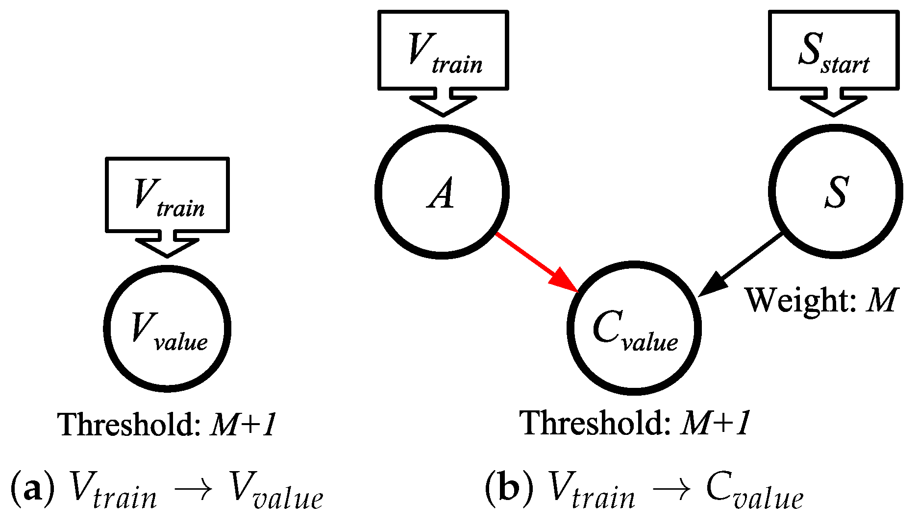
The simplest network converts a spike train to a value. It is shown in Figure 3a, and works on strict and lax spike trains. The network is trivial, simply allowing the V v a l u e neuron to accumulate V spikes, each of which adds one to the neuron’s potential. It needs to run for M timesteps to allow for V v a l u e to store its maximum value.
In Figure 3b, we show a network to convert a spike train to its complement. It does so by having neuron A convert the spike train to negative spikes. These spikes are sent to the C v a l u e neuron, subtracting V from the potential of the neuron. At timestep 0, the S neuron spikes, sending a spike with a weight of M that arrives at timestep 1, the same time as the first spike from A. Therefore, at timestep M, the potential of the C v a l u e neuron stores C = M V . This network works on both strict and lax spike trains.
To summarize, the two networks in this section take a spike train, either strict or lax, with V spikes over a duration of M timesteps, and result in either the V v a l u e neuron having a potential of V, or the C v a l u e neuron having a potential of C.

5.2. V t i m e V t r a i n , V v a l u e

In Figure 4, we show an SNN that converts a value V, encoded as a time, into a spike train of V spikes, and to a neuron whose potential is V. This network works by having the S neuron cause the V t r a i n neuron to start spiking, once per timestep, at timestep 1. The spike labeled V t i m e , arriving at timestep V, causes the neuron B to spike at timestep V, sending a negatively charged spike, arriving at the V t r a i n neuron at timestep V + 1 . That spike stops neuron V t r a i n from firing further. Therefore, V t r a i n spikes a total of V times, starting at timestep 1.
As in Figure 3a, the spike train is converted into a value in neuron V v a l u e . We note that if the conversion to V v a l u e is not desired, then the V v a l u e neuron may be deleted from this network.
The network must run for M + 2 timesteps if V v a l u e is included, and M + 1 timesteps if V v a l u e is not included. We note, though, that neuron S is reset at timestep 1, and neuron B is reset at timestep M + 1 . Therefore, the network may be reused after M + 1 timesteps.

5.3. V v a l u e C t i m e , C t r a i n , C v a l u e

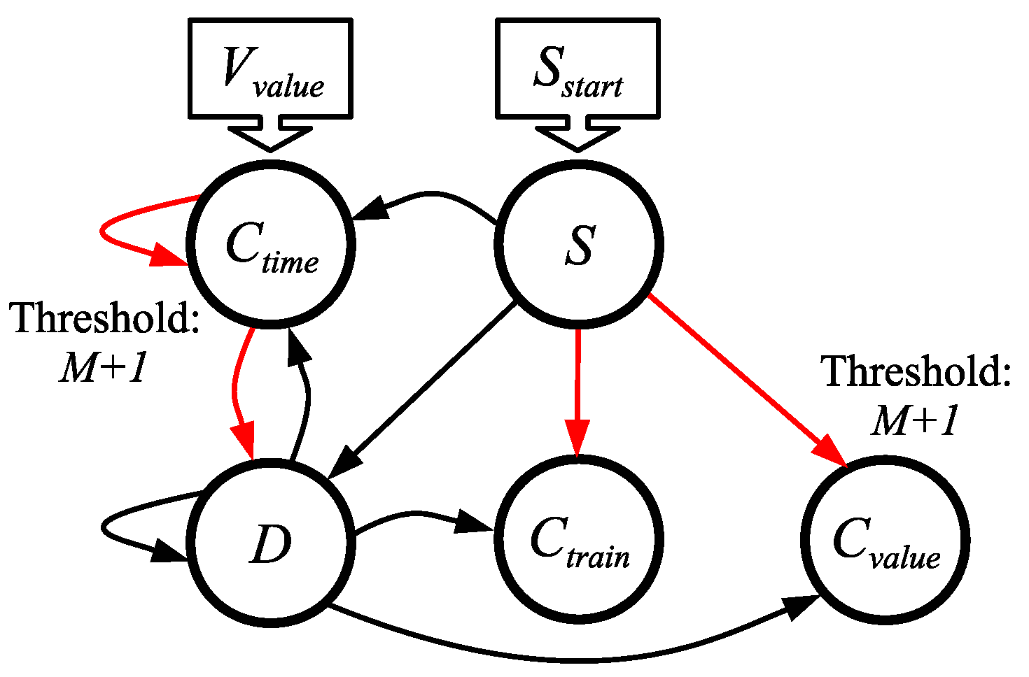
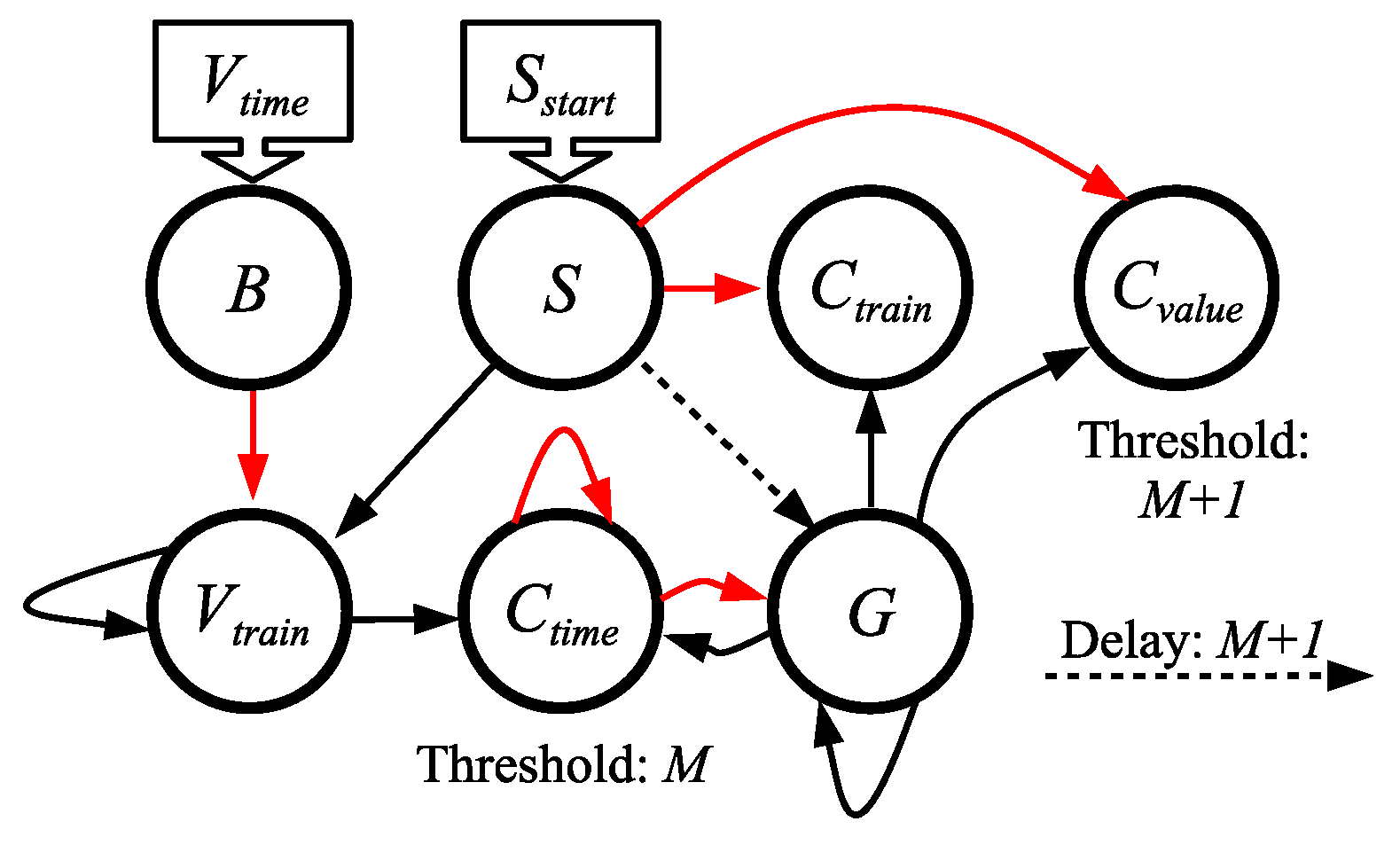
When a neuron has a potential of V and a threshold of M + 1 , we may cause it to spike by adding C + 1 to its potential. We use this fact to convert values stored in potentials into complements that may be represented by values, times or spike trains. We show all of the conversions in one network, in Figure 5.
We assume that neuron C t i m e starts at timestep 0 with a potential of V. We also apply a spike to the S neuron at time 0 with S s t a r t . We run the network for M + 3 timesteps, and the value C is stored/communicated in three ways:
  • The C t i m e neuron fires at timestep C + 1 ( R = 1 ).
  • The C t r a i n neuron fires C times, once per timestep, starting at timestep 3 ( R = 3 ).
  • The C v a l u e neuron is guaranteed to have a potential of C after M + 3 timesteps.
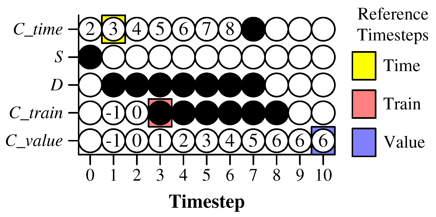
Unlike the previous three networks, which are straightforward, this network’s operation is a little subtle, so we provide an example in Figure 6. In this example, we convert the value V = 2 into C = 6 , with a the maximum value of M = 8 . In the example, the C t i m e neuron starts with a potential of 2, and a spike is applied to S at time 0.
The spike from S causes four actions at timestep 1: It adds one to the potential of C t i m e , so that its potential is 3. It causes the D neuron to start spiking, and it sets the potential of both C t r a i n and C v a l u e to −1. Starting with timestep 1, D starts spiking, which keeps adding one to the potential of C t i m e every timestep. That means that at timestep C + 1 , C t i m e ’s potential reaches M + 1 , and it fires. That performs the conversion to time. The C t i m e neuron sends a negative spike to D, which makes it stop firing, and the negative spike to itself cancels the extra spike coming from D.
The D neuron thus spikes C + 1 times. Since we want a spike train of C spikes, we set up C t r a i n to spike one fewer time than D. That is why it spikes C times starting at timestep 3. Finally, since D spikes C + 1 times, and the potential of C v a l u e is set to −1 at timestep 1, D s spiking causes the potential of the C v a l u e neuron to reach V at timestep C + 3 . To allow for C to achieve its maximum value, we must run the network for M + 3 timesteps.
There are two additional notes about this network. First, the C v a l u e neuron is useless unless one is converting to a C v a l u e , and the C t r a i n neuron is useless unless one is converting to a spike train, so those neurons may be deleted if they are unused. Second, the C t i m e , S, D, and C t r a i n neurons all have their potentials reset to zero at the end of the conversion, which means that they may be reused without any explicit resetting of the network. The C v a l u e neuron, on the other hand, does not reset its value—it must be used in other ways (for example, by converting to time or a spike train).

5.4. V t r a i n V t i m e

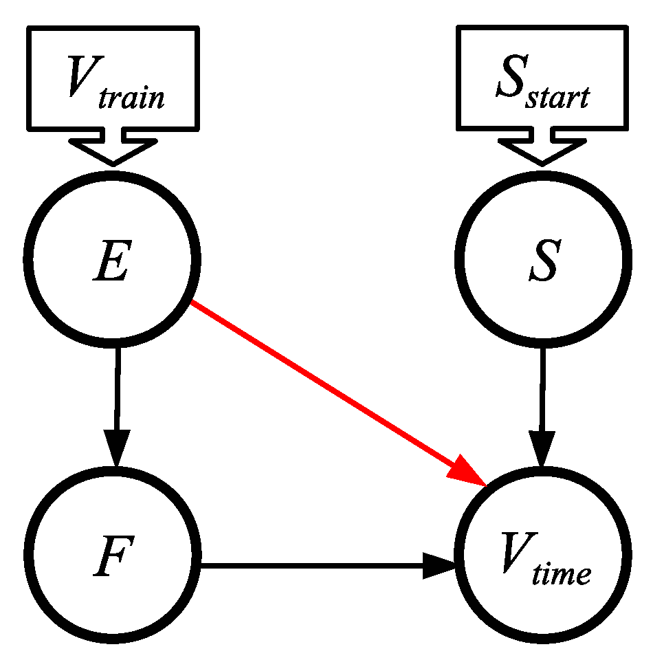
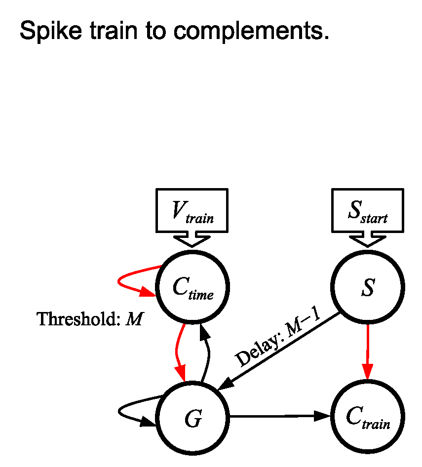
The simple network in Figure 7 converts a spike train into a time. Specifically, when V spikes are sent to the E neuron, one per timestep starting at timestep 0, and a single spike is sent to S, also at timestep 0, then the V t i m e neuron spikes at time V + 1 . Therefore, R = 1 and the network must run for M + 2 timesteps.
The mechanics of this network are straightforward—for each spike in the spike train at timestep i, a negatively charged spike arrives at V t i m e at timestep i + 1 , and a positively charged spike arrives at timestep i + 2 . Moreover, the spike from S arrives at timestep 1. Therefore, from timesteps 1 to V, two spikes arrive at V t i m e , one with a charge of 1 and one with a charge of −1. Its potential stays at 0. At timestep V + 1 , there is no negatively charged spike, but there is one positively charged spike. Therefore, at timestep V + 1 , V t i m e spikes.
The spike train going into neuron E must be strict. For a lax spike train, one should convert to a value as in Figure 3a or b, and then convert that value into a time.

5.5. V t r a i n C t i m e , C t r a i n

The remaining networks in this section are compositions and slight modifications to networks in the previous subsections. The first of these converts a spike train of V spikes into its complement as a time and a spike train. The network is shown in Figure 8. It is a composition of the network in Figure 3a, which converts the spike train to its value, and Figure 5, which converts values to complements.
The mechanics of this network are as follows. We input V, as a strict spike train, and desire to have C communicated as a time or spike train. To make the explanation easier, suppose 0 < V < M . Then after timestep V 1 , the input spike train causes the C t i m e neuron to store a potential of V. The spike from S to G arrives at timestep M 1 , at which point G starts to fire. Thus, at timestep M, the C t i m e neuron starts accumulating charge. When it accumulates C units of charge from G, which is at timestep M + C , it fires. Therefore, the C t i m e neuron communicates C as a time, with R = M 1 .
When C t i m e fires, its two negative synapses stop G from firing, and cancel the final spike from G. Thus, G fires a total of C + 1 times. Because of the one negative spike from S, C t r a i n fires one less time than G, which is C times. Its reference timestep is M + 1 , which is when G s second spike arrives.
If C t r a i n is not being used, it may be deleted from the network. If so, then the network runs for 2 M timesteps. If C t r a i n is being used, then the network must run for 2 M + 1 timesteps.
A simple examination of what happens when V = 0 and V = M confirms that its behavior fits with the above description. Therefore, we summarize as follows:
  • The C t i m e neuron fires at time C + M 1 . In other words, R = M 1 .
  • The C t r a i n neuron fires C times, once per timestep, starting at timestep M + 1 .
  • The network must run for 2 M + 1 timesteps, after which point it may be reused.

5.6. V v a l u e V t i m e , V t r a i n

The network in Figure 9 composes the networks in Section 5.1 and Section 5.3 to convert a value to a time and a spike train. It borrows the C t i m e and D neurons from Figure 5, and the synapse from D to V t i m e inserts the complement into V t i m e ’s potential. The delayed synapses from S convert that complement into values, as in Figure 5 again.
We do not explain the mechanics of this network further. However, we summarize as follows:
  • The value V is sent to C t i m e at timestep 0.
  • S is made to spike at timestep 0.
  • V t i m e spikes at timestep ( M + 2 ) + V . Therefore, R = M + 2 .
  • V t r a i n spikes V times, one per timestep, starting at timestep R = M + 3 .
  • The network must run for 2 M + 3 timesteps.

5.7. V t i m e C t i m e , C t r a i n , C v a l u e

The network in Figure 10 converts times to complements. It is a direct composition of the networks in Section 5.2 and Section 5.3. Specifically, we start with the network in Figure 4. That network converts V t i m e to V v a l u e ; however, we rename the V v a l u e neuron from Figure 4 to C t i m e from Figure 5, and append the rest of that network. We borrow the rest of the neuron names from the two figures.
Because this network works just like the networks in Section 5.2 and Section 5.3, we do not explain its mechanics further. We summarize as follows:
  • V is made to spike at timestep V.
  • S is made to spike at timestep 0.
  • C t i m e spikes at timestep M + 1 + C . Therefore, R = M + 1 .
  • C t r a i n spikes C times, one per timestep, starting at timestep R = M + 3 .
  • C v a l u e has a potential of V by timestep R = 2 M + 2 .
  • If either C t r a i n or C v a l u e is not used, it may be deleted from the network.
  • The network must run for 2 M + 3 timesteps if either C t r a i n or C v a l u e is used. Otherwise, it must run for 2 M + 2 timesteps.

5.8. Summary of Conversion Networks

We summarize the 15 conversions in Table 2. In the table, we include the following values for each conversion:
  • The figure that specifies the conversion.
  • N: The number of neurons in the network, where neurons that are unnecessary for the conversion are deleted.
  • S: The number of synapses in the network, where synapses that are unnecessary for the conversion are deleted.
  • R: The reference timestep for the conversion.
  • T: The number of timesteps required to perform the conversion.
Table 2. Summary of the 15 conversions performed by the networks specified in this paper.
     ConversionFigureNSRT
          V v a l u e C v a l u e Figure 548 M + 2 M + 3
          V v a l u e V t i m e Figure 9513 M + 2 2 M + 2
          V v a l u e C t i m e Figure 5362 M + 2
          V v a l u e V t r a i n Figure 9513 M + 3 2 M + 3
          V v a l u e C t r a i n Figure 5483 M + 3
          V t i m e V v a l u e Figure 444 M + 2 M + 3
          V t i m e C v a l u e Figure 10611 2 M + 2 2 M + 3
          V t i m e C t i m e Figure 1059 M + 1 2 M + 2
          V t i m e V t r a i n Figure 4331 M + 2
          V t i m e C t r a i n Figure 10611 M + 3 2 M + 3
          V t r a i n V v a l u e Figure 3a10 M 1 M
          V t r a i n C v a l u e Figure 3b32M M + 1
          V t r a i n V t i m e Figure 7431 M + 2
          V t r a i n C t i m e Figure 835 M 1 2 M
          V t r a i n C t r a i n Figure 847 M + 1 2 M + 1

6. Case Studies/Experiments

In this section, we detail a case study on constructing an SNN with specific properties, and two experiments that improve the communication performance of applications on neuromorphic FPGAs. They all leverage conversion networks to achieve their goals.
The applications in this section follow a typical application loop for AI agents:
  • The application has observations or features to send to the AI agent, which is implemented on an SNN that has been designed or trained specifically for the application. The application’s observations will be sent by a host.
  • The host converts observations/features into spikes, using one of the three communication techniques described in Section 4 above, which are applied to specific input neurons of the SNN.
  • The SNN runs for some number of timesteps, which is application-specific.
  • The spiking behavior of specific output neurons is communicated to the host, which converts the spikes to actions for the application (or a classification in the case of a classification application). The communication from the SNN to the host is either by time or by spike train (lax).

6.1. Case Study: Comparing Spike Counts

In this case study, we focus on applications that utilize an SNN to make a binary decision. This can be a classification application with two categories or a control application with two actions. The application follows the loop above, and its SNN has two output neurons, call them Y and N, which communicate votes by spike train (lax) to the host. The host counts the spikes on each output neuron, and selects the output that spikes the most, breaking ties in favor of Y or N. Without loss of generality, in this work, we break ties in favor of Y.
There are many applications that process outputs in this manner. The two in Section 6.2 and Section 6.3 below are examples, but there are many other examples in the literature [20,34,36].
As demonstrated below, communication between a host and neuroprocessor is often very expensive compared to the speed of the neuroprocessor. Therefore, it is advantageous for the host to reduce communications with the neuroprocessor. One way to reduce communication is to convert the communication of outputs from a spike train, which requires a communication event for every spike, to a single spike, which requires only one communication. We perform this conversion in this subsection, by converting V t r a i n on each output neuron to C t i m e . We then compare the times, so that if C t i m e from one output is smaller than C t i m e on the other, we generate a spike on one output neuron. If it is not, then we generate a spike on a second output neuron.
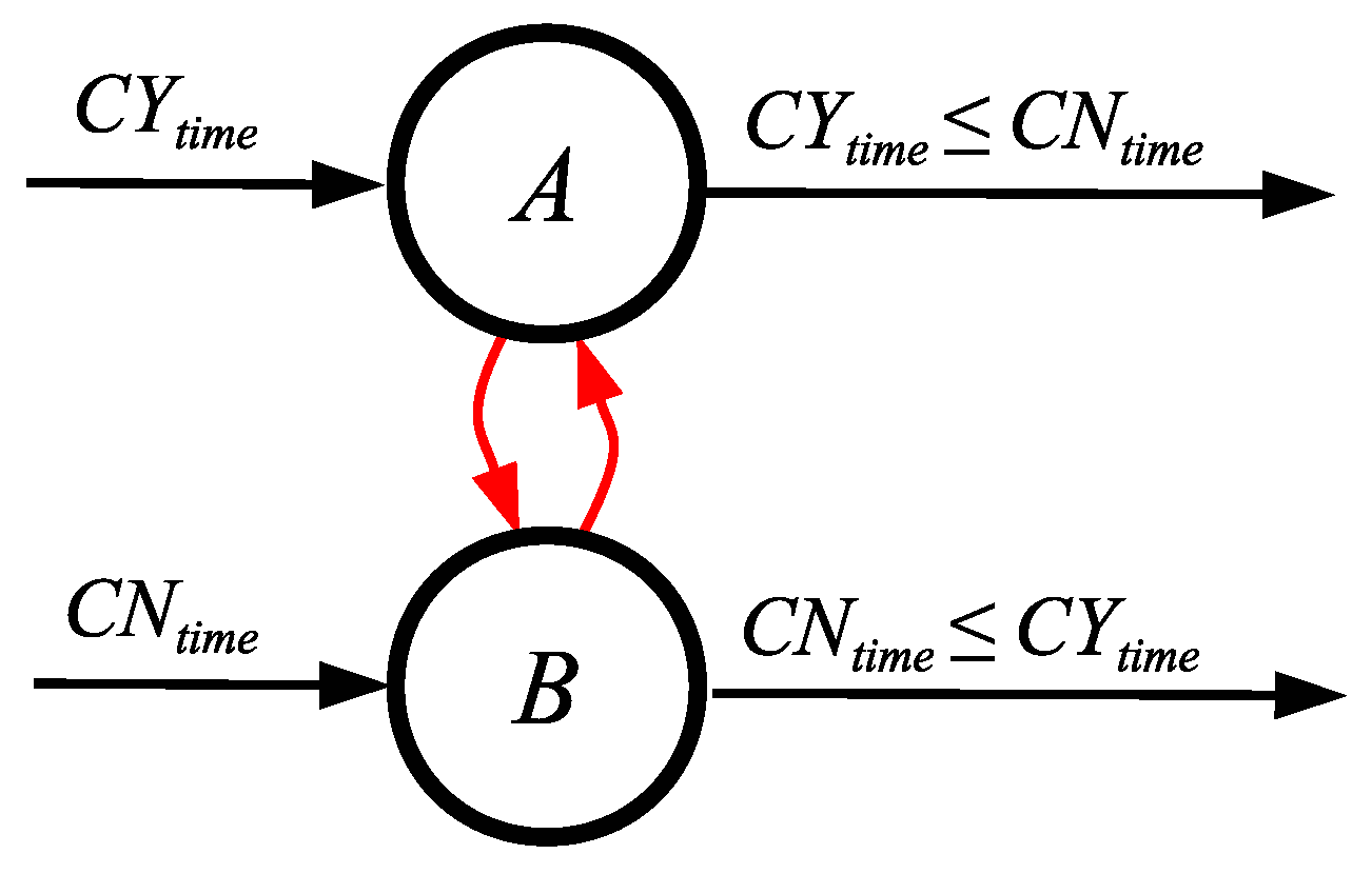
The process is depicted in Figure 11. The conversion of spike counts to times allows us to construct an SNN to compare the times. One simple, but flawed network to perform this comparison is shown in Figure 12. This network works as desired when C Y t i m e < C N t i m e , which causes neuron A to spike and neuron B to reset, and when C N t i m e < C Y t i m e , which causes neuron B to spike and neuron A to reset. However, when C N t i m e = C Y t i m e , both neurons spike, and their potentials are set to −1 on the next timestep. That is the flaw in the network.
We may fix this flaw by adding a network from [18] that performs the binary AND operation. This network has three neurons, C, D and E, where
  • C fires if and only if A and B both fire;
  • D fires if and only if A fires, but B does not;
  • E fires if and only if B fires, but A does not.
In Figure 13, we show how this AND network fixes the flaws of the network in Figure 12. In Figure 13, Y fires when C Y t i m e C N t i m e , N fires when C N t i m e < C Y t i m e , and all neurons are reset when the operation completes.
We show the entire network in Figure 14. Although it appears complex, it is the straightforward composition of four networks: two V t r a i n C t i m e networks, the “flawed” comparison network from Figure 12, and the binary AND network from [18] to fix the flaw. This network must run for 2 M + 3 timesteps, after which it may be reused.

6.2. Experiment: Inference with the MAGIC Dataset

The first experiment performs an inference task on a classification dataset on a neuromorphic FPGA. The dataset is the MAGIC Gamma Telescope dataset, in which high-energy gamma particles are classified in a simulated atmospheric Cherenkov telescope [37]. We selected this dataset as it has been used previously to evaluate the performance of the neuromorphic FPGA Caspian [17]. The dataset contains 13,376 observations, where each observation is composed of ten numeric features and belongs to one of two classifications. The observations are split equally among the two classifications in both the training and the testing sets. As in the previous evaluation, we partitioned the dataset into 75% training observations and 25% testing observations.

6.2.1. Training

We trained classification agents on the Reduced Instruction Spiking Processor (RISP) neuroprocessor [7]. This is a basic neuroprocessor that features integrate-and-fire neurons and synapses with unit delays. As such, it has the characteristics required to implement the conversion networks defined in this paper. RISP has an open-source simulator and FPGA implementation, both of which we use for our experiments. Although RISP allows both integer and floating point potentials, thresholds, and weights, we employ its discrete setting, where these values are all integers constrained from −127 to 127. The discrete setting is required for FPGA implementation.
We trained neuromorphic agents for this dataset using the EONS genetic algorithm for neuromorphic processors [38]. We varied several parameters in this experiment. First is the technique for encoding the features of the dataset into spikes:
  • Value: The features are converted into values between 0 and 127 using linear interpolation, and these values are applied to the input neurons.
  • Time: The features are converted into times between 0 and 47, and each feature is encoded by a single spike applied to the appropriate input neuron at the encoded timestep. We also used values between 0 and 95.
  • Spike Trains: We set a maximum spike train size of 8, 12, 16, 24 or 48, and converted the features into a spike train whose size is between 1 and the maximum. We then applied the spike trains every n timesteps, where n equals 48 divided by the maximum spike train size, or 96 divided by the maximum spike train size.
We ran the application loop described in Section 6 above, with a simulation time of 64 timesteps (when the inputs are encoded over 48 timesteps), or 128 timesteps (when the inputs are encoded over 96 timesteps). We used two output neurons and compared their spike counts to determine the classification. During training, we performed 100 runs per parameter setting.
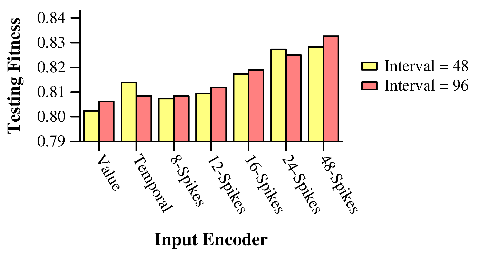
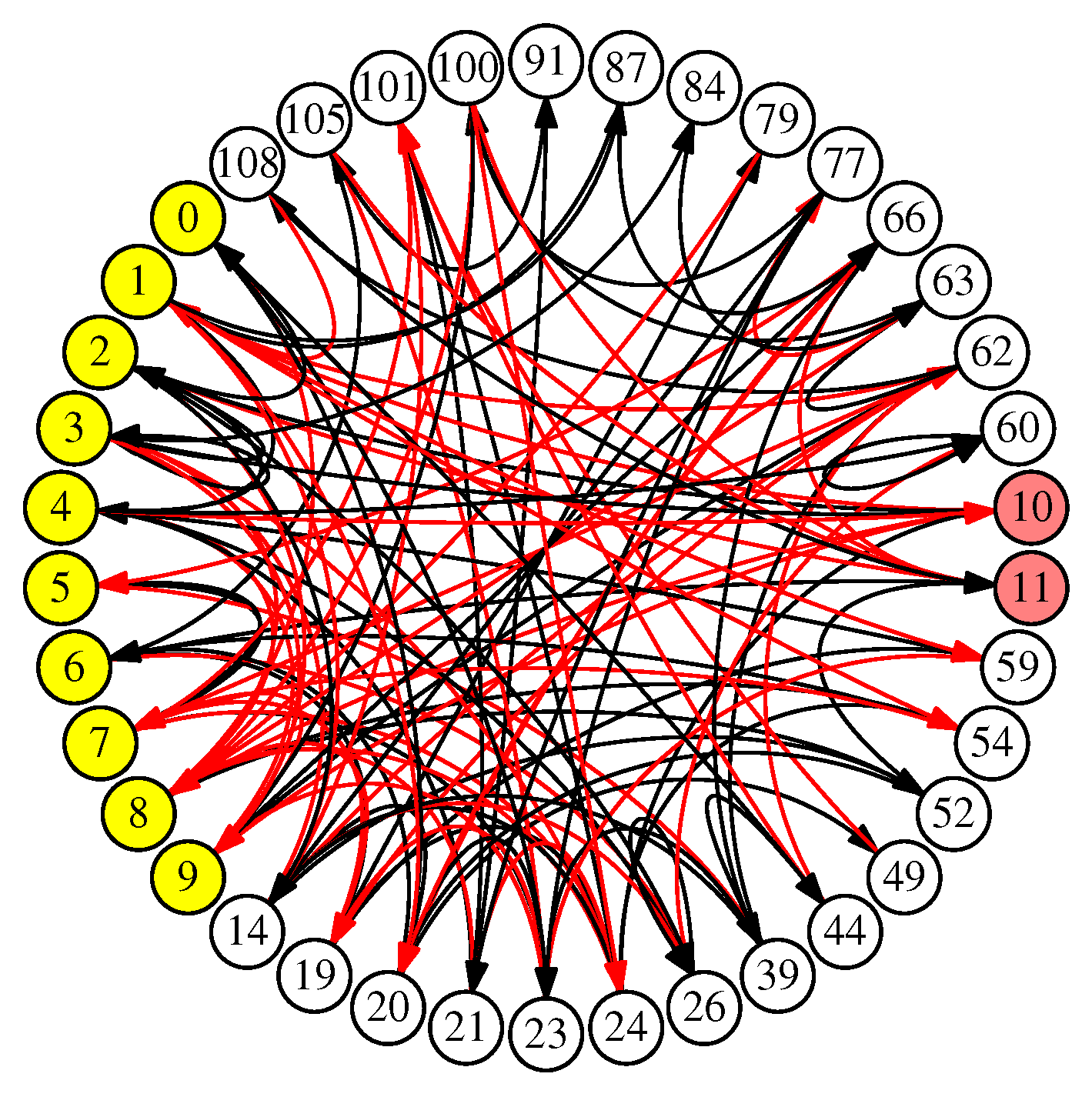
We display the results of training in Figure 15. The best fitness values are on par with those reported by Mitchell et al., which also includes traditional machine learning optimizations [17]. The best networks employed spike-train encoders, with the best overall network employing the most communication-heavy encoder—up to 48 spikes over an interval of 96 timesteps, with a total simulation time of 128 timesteps. This network is the focus of our FPGA experiment. The network contains 10 input neurons, 2 output neurons, and 26 hidden neurons. It has 120 synapses, and includes cycles and self-loops, which is typical for networks created by genetic algorithms.
We display the network in Figure 16. In the figure, the input neurons are colored yellow, and the output neurons are colored pink. Excitatory synapses are shown in black, and inhibitory synapses are shown in red. This network achieves an F1 score of 0.832 on the testing dataset.
Like other neuromorphic hardware projects listed in Section 2, the RISP FPGA features very fast execution of the SNN, but slow communication with the host. Specifically, the FPGA processes the SNN at a rate of roughly 100,000,000 timesteps per second, while communication over the Universal Asynchronous Receiver/Transmitter protocol (UART) is in the range of 10,000 bits per second. Therefore, the encoder that trains the best, employing spike trains of up to 48 spikes, has the worst communication behavior. Moreover, to count the output spikes, the RISP FPGA has each spike occur as a separate communication event to the host, which is also a performance penalty.

6.2.2. Conversions to Improve Communication

To improve performance, we use the networks specified previously in this paper. Specifically, for each feature, we employ a V v a l u e V t r a i n conversion network (Figure 9), so that the host may send single values rather than spike trains. We also use the network specified in the previous section (Figure 14) to convert the output spikes into a single spike on one of two output neurons. This reduces the communication burden significantly without changing the underlying behavior of the network.
The network is shown in Figure 17. The network is the composition of 13 subnetworks and an extra S neuron. The subnetworks are explained as follows:
  • Ten subnetworks are labeled “Figure 9(x2).” These convert the input features, that are applied to the SNN as single values, to spike trains of up to 48 spikes, applied every two timesteps. We discuss how to achieve “every two timesteps” below, but that is why the networks are labeled with “(x2).”
  • The original network from Figure 16 that performs the classification on spike trains of up to 48 spikes, applied every two timesteps. As described above, this network runs for 128 timesteps, and then the spikes on its output neurons (labeled 10 and 11) are counted and compared to perform the classification.
  • The subnetwork labeled “Figure 14.” This network converts the output spikes from the original network into a single spike on one of two output neurons.
  • The subnetwork composed of the K neuron and its synapses. The function of this subnetwork is to prevent neurons 10 and 11 from spiking when their 128 timesteps are finished, because the network needs to run extra timesteps to convert the output spikes.
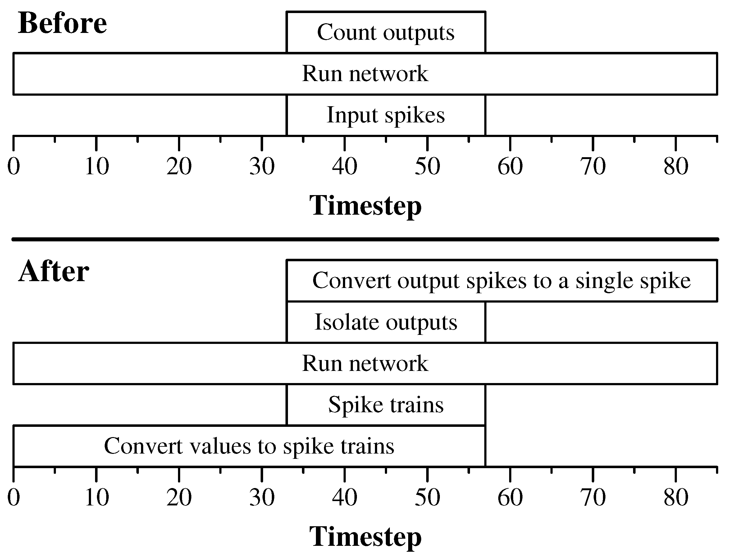
We show the timing of these subnetworks in Figure 18. There are a few subtle features of these subnetworks that bear explanation.
First, each of the subnetworks, besides the original, requires a starting spike. Rather than require the host to send 12 starting spikes, which would penalize performance, we instead have the spike apply one spike to the S neuron in Figure 17, and that neuron sends all of the starting spikes to the other networks.
Second, the spike trains in the original network come every other timestep rather than every timestep. Thus, the V v a l u e V t r a i n networks need to produce a spike train where the spikes arrive every two timesteps. That may be achieved by simply multiplying the delay of every spike by two. This is denoted in Figure 17 by “Figure 9(x2).” The spike trains from these networks start at timestep 2 ( M + 3 ) = 2 M + 6 . Since the original spike train has a maximum of 48 spikes, M = 48 , meaning the spike trains start at timestep 102. This is the timestep where “Run original network” starts in Figure 18. The conversion network needs to run for another 96 timesteps to complete sending its spikes. It resets itself by design, so after timestep 198, it has no more activity.
Third, because we use a single S neuron for all of the starting spikes, the spikes from S arrive to the “Figure 9(x2)” networks at timestep 1. Therefore, we subtract one from the delays of all of the S neurons in Figure 9(x2).
Fourth, the conversion network labeled Figure 14, needs to start its operation at the same time as the original network. For that reason, we set the delay of the synapse from the S neuron in Figure 17 to the S neuron in Figure 14 to 101.
Fifth, the original network runs for 128 timesteps, so the outputs may spike up to 128 times. Thus, in the subnetwork from Figure 14, we must set M to 128. Therefore, that subnetwork runs for 2 M + 3 = 259 timesteps. Since it starts at timestep 102, the entire network runs for 361 timesteps.
Sixth, since the original network only runs for 128 timesteps, but in order to perform output conversion we run it for an additional 131 timesteps, we must account for the fact that the original output neurons, labeled 10 and 11 in Figure 17, may spike during this additional time. We only want to count the spikes that occur during the original 128 timesteps. Therefore, we add a neuron, labeled K, and start it spiking during the last of the 128 timesteps. It has synapses with delay 1 and maximal negative weight to neurons 10 and 11, disabling them from spiking when the original 128 timesteps are completed.
We summarize the original network and the network with conversions in Table 3. They demonstrate the space–time tradeoff, as the original network is smaller and requires fewer neuromorphic timesteps, but also requires more communication. The converted network is larger and requires more neuromorphic timesteps, but reduces the communication drastically.

6.2.3. Performance on FPGA

We ran our experiment on a Basys 3 Artix-7 FPGA board configured to run networks using the RISP open-source FPGA implementation [7]. The board is connected to a Raspberry Pi Pico microcontroller configured to send input spikes to the FPGA and to read output spikes. The observations from the testing set are converted to input spikes for the Pico to send, and the output spikes are recorded and stored by the Pico. Communication is over UART and we perform the tests in batches of 3000 observations. We show the measurements from running the two networks in Table 4.
The results are as anticipated—even though the networks and running times are approximately 2.5 times larger, the converted network runs over 23 times faster than the original network due to the reduction in communication. This demonstrates the potential for conversion networks to improve performance drastically.
In Table 4, we also include the power consumption reports from Vivado. These are for the Artix-7 FPGA chip, and not for the entire Basys3 board, and therefore represent the converted network in its worst light. Because of the larger SNN and increased spiking activity, the converted network consumes more dynamic power on the chip. However, the total power consumption is still very low, with the increase being less than 20 percent.

6.3. Experiment: The Cart–Pole Application

Our second experiment focuses on the well-known Cart–Pole problem. In this problem, an AI agent must keep a pole balanced on a cart, and keep a cart within track limits, given observations every 0.02 s. As a result of the observations, the agent may push the cart right or left at a fixed power setting. This problem has been well-studied, and, as the default parameters of the problem are too easy [39], we focus on the “Hardest” parameters from [40]. With these parameters, the agent is only given two observations—the position of the cart and the angle of the pole. The “standard” setting also gives the agent velocities.
In [40], an SNN is presented that keeps the pole upright for an average of 3 min, 59.8 s on a mission time of 5 min for the “Hardest” setting. This network is published as part of the RISP open-source software [7]. The network uses an “argyle” encoder, where each observation is encoded into exactly nine spikes applied to two of four input neurons. The network runs for 24 timesteps, and the decoder is a binary-decision decoder, employing two output neurons that we name L and R. Whichever of these neurons spikes more in the 24 timesteps determines whether to push the cart left or right, with ties broken in favor of L. Therefore, at each 0.02 s interval of the application, the neuroprocessor receives 18 input spikes, runs for 24 timesteps, and then produces up to 48 output spikes, which are counted to determine the action.
Clearly, this network is a candidate for using conversion networks to improve performance, as in the previous experiment. However, there are a few subtleties that force us to take a different approach with the conversions. To explain, consider the classification example in the previous subsection. With classification, each inference is independent, which means that we clear the network between inferences. Therefore, running the network for additional timesteps does not affect the computation. Specifically, when we convert the input, all of the neurons and synapses have been cleared. Therefore, the only neurons that receive spikes are those participating in the conversion. When we convert the output, we “neutralize” the output neurons with the K neuron, and we are not concerned with the activity in the other neurons, as they are cleared when the inference is over.
With the Cart–Pole application, we do not clear the network between intervals. The reason is that we want the SNN to have memory of previous intervals. This is especially true when we are not using velocities as observations—the SNN needs to have some notion of system state. Therefore, adding extra timesteps to the beginning and end of the interval, to perform conversion, will corrupt its state, and the network will not perform identically to before conversion.
We solve this problem by training a different SNN, which is amenable to conversion. With this network, we simulate for 85 timesteps instead of 24. We apply the input spikes starting at timestep 33, and then only count output spikes during the 24 timesteps starting with timestep 33. During the final 28 timesteps, we process the network, but do not count output spikes. The process is shown in the top of Figure 19. Using the training parameters suggested in [40], we trained a network that averaged 3 min, 51 s on the application.
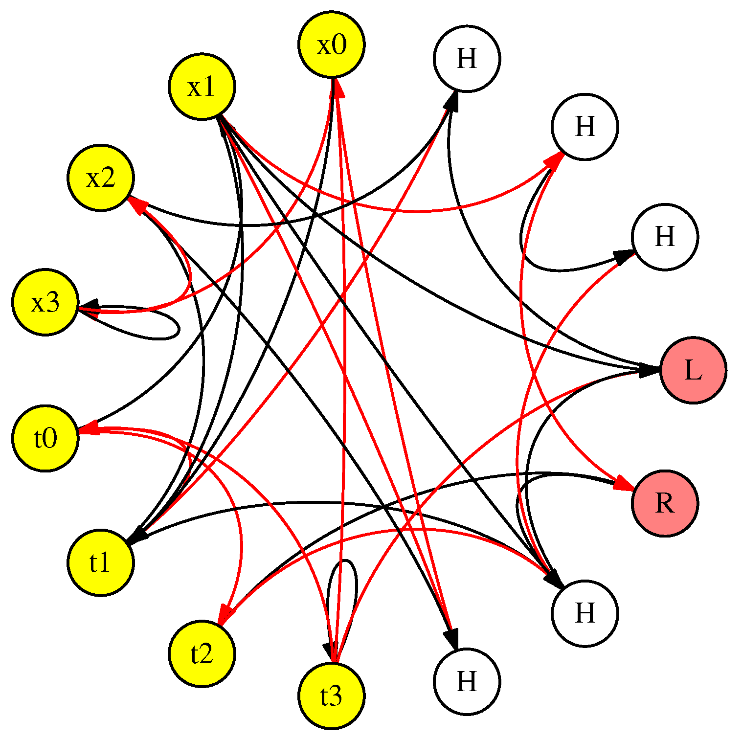
The network is shown in Figure 20. It has eight input neurons—four for the cart position ( x 0 x 3 ) and four for the pole angle ( t 0 t 3 ). It has two output neurons—one for “left” and one for “right”. Plus, it has five hidden neurons labeled “H”. It has 30 synapses, 16 of which are excitatory (black) and 14 of which are inhibitory (red). It uses the “RISP-127” setting of RISP, which means that neuron thresholds are integers between 1 and 127, and synapse weights are integers between −127 and 127.
We apply conversion networks in the following way. Instead of having the host send spike trains as inputs, it sends values between 0 and 8 to eight conversion networks. Those networks are like the networks in Figure 9, except the delay of each synapse is multiplied by three. The conversion networks convert the values to spike trains of up to 8 spikes, where the spikes appear every three timesteps, starting at timestep 33.
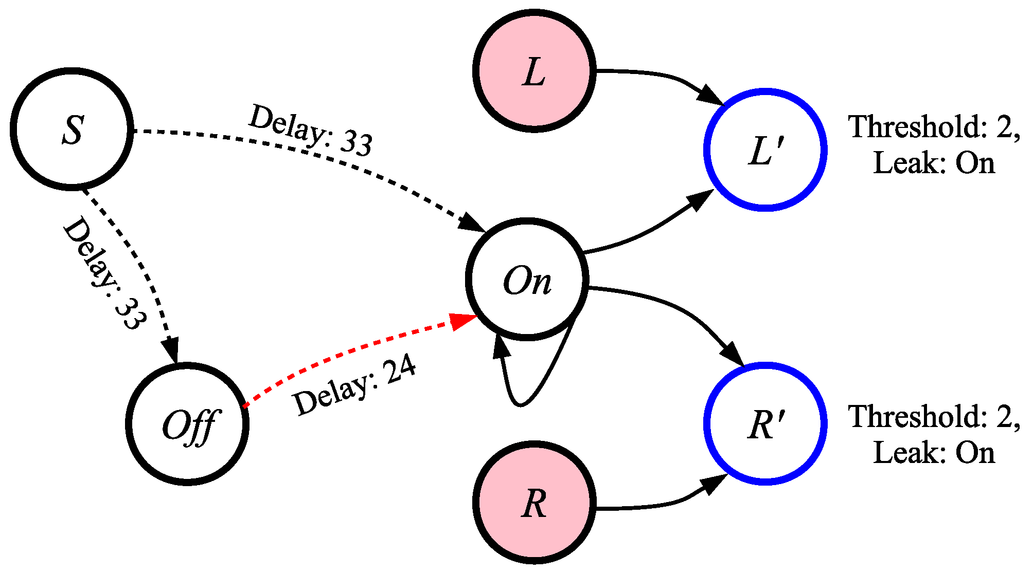
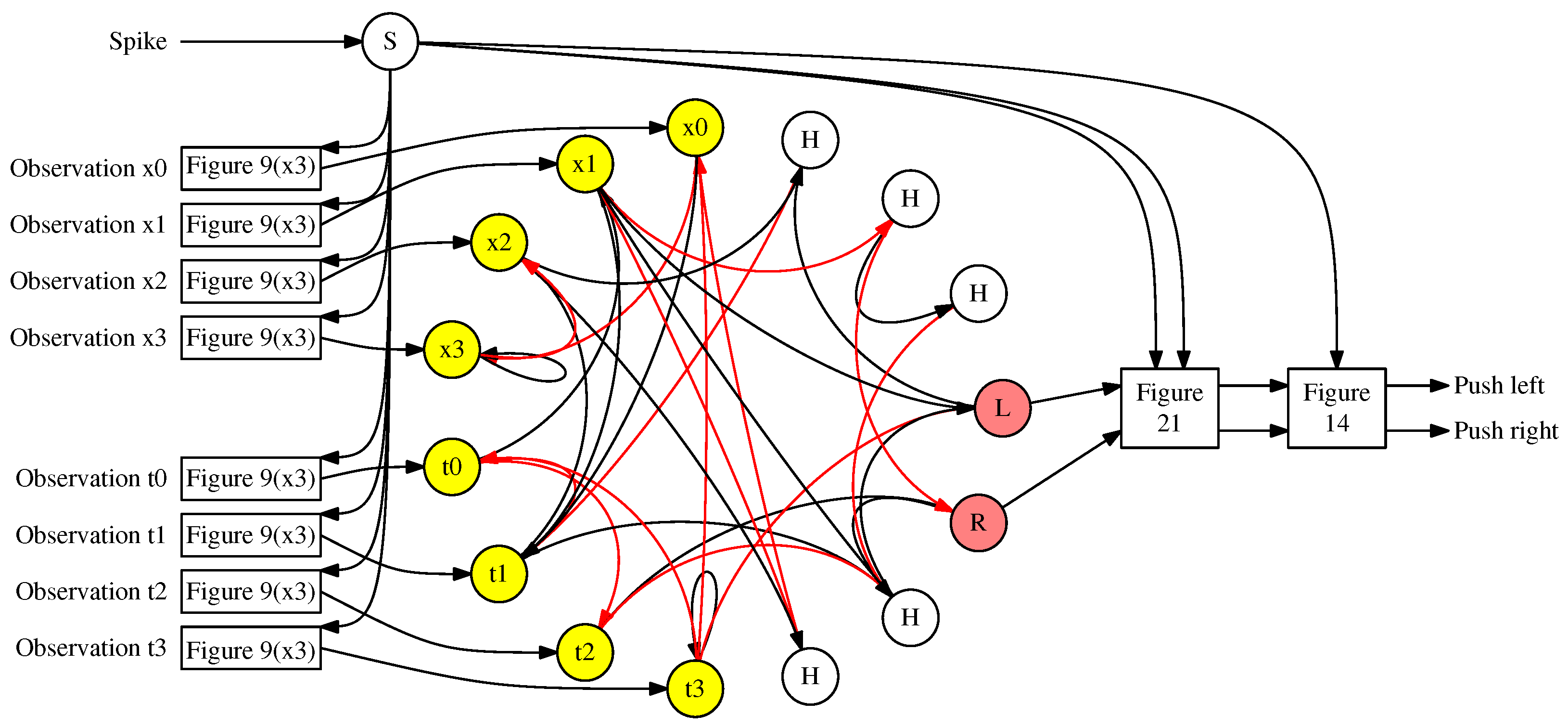
We also use a voting network as shown in Figure 14, where M = 24 , because there may be up to 24 spikes on each output neuron. Finally, we add an additional subnetwork shown in Figure 21 between the output neurons L and R and the voting network, so that only spikes from the 24 timesteps starting with timestep 33 are counted for the output. This subnetwork is straightforward—the neuron labeled On spikes exactly 24 times, starting with timestep 33. This neuron has synapses to two AND networks from [18]—one for L and one for R. Thus, starting at timestep 34, the neurons labeled L and R only fire when L / R fire during timesteps 33 through 56. In other words, the network isolates the output spikes so that the only output spikes counted are those during the correct timesteps.
We remark that the L and R neurons must be configured to leak their charge completely at every timestep. This feature is part of the RISP neuroprocessor, so we are able to implement the network in our tests. We can obtain the same functionality without leak [18], but the resulting network is much more complex, so we omit it here in favor of the simpler network.
The entire network is shown in Figure 22. To summarize again, a single spike is sent to the S neuron at timestep 0. Moreover, each of the two observations are converted, using an “argyle” encoder, to two values between 1 and 8, where the sum of the values is 9. Each value is spiked into one of the eight input neurons in the networks labeled “Figure 9(x3).” These networks convert the values into spike trains, where spikes appear every three timesteps starting with timestep 33. From timesteps 33 through 56, the outputs on the output neurons L and R are isolated by the network in Figure 21, and converted into a single spike by the network in Figure 14. That spike determines whether to push the cart left or right.
We summarize the original network and the network with conversions in Table 5. As in the MAGIC example, the conversion subnetworks have increased the number of neurons and synapses in the network significantly, while at the same time reducing the number of input and output events that must be communicated with the host. Unlike the MAGIC example, the overall number of timesteps is the same for both networks. That is because we trained the original network to accommodate the conversion networks.

Performance on FPGA

As in Section 6.2, we used the RISP open-source FPGA implementation [7] to convert the original and converted Cart–Pole networks to FPGA bitstreams. We then used the same experimental setup as in Section 6.2 to time the performance. The results are in Table 6.
Like the MAGIC test, the larger converted network decreases the communication load significantly, from 91.14 bytes per observation down to 12. This results in a speedup factor of 4.31, bringing the latency of processing observations from 76.62 ms to 12.16 ms. This reduction in time would be essential in an embedded setting, as the processing of observations in the Cart–Pole application must occur every 1/50 s, or every 20 ms. With its extra communication burden, the original network would not be able to “keep up” with the application in this implementation. The converted network, on the other hand, finishes each observation in 12.16 ms, thereby having ample spare time to “keep up” with the application.
The power numbers are similar to the MAGIC application.

7. Discussion

There are two themes that permeate this paper. The first involves information storage and communication in SNNs. We have demonstrated that three techniques for storing and communicating information—values, times, and spike trains—may be treated interchangeably within an SNN. They each have distinct properties within the network:
  • Values may be stored in the network, but it requires a conversion to time or a spike train to “read” a value that is stored in the potential of a neuron.
  • Spike trains communicate values from one neuron to another, but those trains must be converted into values to store them in a neuron. Spike trains are also inefficient as a mechanism to communicate with a host.
  • Times communicate values from one neuron to another, but require reference times to have meaning. Like spike trains, they must be converted into values to store them in a neuron. They are efficient as a mechanism to communicate with a host because they only require one event.
One liberating feature of the interchangeability of techniques for storing and communication of information is that it allows one flexibility in designing and training SNNs. An example of this is the network presented in Section 6.1, which builds a vote-counting network based on the fact that it is simple to compare two times neuromorphically. A second example is the training experiment with the MAGIC dataset, in Figure 15, where employing long spike trains for encoding input was much more successful than using other encoding techniques.
The second theme is of this paper is the effectiveness of composing subnetworks to achieve various goals in network design and training. Again, we highlight the network in Section 6.1, which we designed by hand by composing three subnetworks:
  • The network V t r a i n C t i m e .
  • A network to compare times and spike different output neurons as a result of differing spike times.
  • A network from [18] that performs a binary AND operation to handle the specific case of two spikes arriving at the same time.
The networks in both experiments were the composition of four types of subnetworks:
  • An original network that takes spike trains as inputs and makes a binary decision based on spike counts for outputs.
  • Separate V v a l u e V t r a i n networks for each input neuron.
  • A subnetwork that isolates the output spikes during certain timesteps. This subnetwork was different in each experiment—the subnetwork in the MAGIC experiment disabled the output neurons when they no longer were to be counted, and the subnetwork in the Cart–Pole experiment used binary AND networks so that the outputs were only processed during the relevant timesteps.
  • The network from Figure 14 that compares counts of output neurons and converts them to a single output spike.
The FPGA implementation in each experiment highlighted the importance of lowering communication to improve performance. In each case, a larger SNN was employed to lower the communication burden, and resulted in greatly improved performance.
A final discussion point is how the encoding techniques and the SNNs presented in Section 5 scale. As summarized in Table 1, encoding using time and spike trains incurs an overhead of O ( M ) for values between 0 and M, while value encoding is much more efficient, at O ( 1 ) . Thus, their overheads are functions of the values being encoded, and not, for example of the size of the SNN that processes them. Although efficient, the drawback of value encoding is that the encoding must be converted to another encoding to communicate it to other neurons or to the host.
The conversion networks in Section 5 all run in O ( M ) time, meaning that from a scalability perspective, they are as efficient as they can be. As with the encodings, their scalability depends on the values themselves, and not on the SNNs that process them. The networks are all O ( 1 ) in size, employing fixed numbers of neurons. Therefore, from a size perspective, these networks scale very efficiently, without any dependence on the values being encoded or the SNNs to which they are attached.
As a final remark involving scalability, there has been research on using a binary representation of numbers with spikes, meaning a maximum value of M may be encoded with O ( l o g M ) spikes. In separate works, Aimone et al. [41] and Wurm et al. [42] demonstrate SNNs that perform basic arithmetic operations on these binary-encoded spike trains. There is less work on leveraging this encoding technique to train SNNs for more complex tasks; however, these encodings may provide an efficient medium for communicating information when composing SNNs.

8. Limitations

One major limitation of this work depends on the perspective of the reader: Although SNNs are inspired by biology, these conversion networks have nothing to do with biology. They are computational in nature, relying on discrete timesteps and integration cycles, rather than biomimicry or machine learning. As such, they do not further our understanding of the computational ability of the brain. On the flip side, they have pragmatic benefits (performance), and like [18,24,25,26,27,43], help the research community build an arsenal of SNNs that may be composed for various tasks.
This paper focuses on utilizing the SNN to reduce the overhead of communication. Obviously, there are other ways of reducing this overhead, such as using faster communication protocols, employing buffering in the host or the neuroprocessor, and implementing aggregate communication primitives on the neuroprocessor. In particular, it is possible for the neuroprocessor to implement an “apply spike train” primitive, which would allow the host to simply specify a neuron, spike count, and period to communicate a spike train. Similarly, if the neuroprocessor reports spike counts rather than individual outputs, then the network from Section 6.1 is unnecessary for improving performance. Unfortunately, since many neuromorphic hardware projects are research-oriented, it is reasonable to expect that advanced communication protocols and primitives will be scarce for the near future. Moreover, faster communication protocols such as PCIe are typically not low-power, which means that although they promise high speed, they are not as applicable to embedded and edge applications. In either case, using the SNN to improve communication remains a universally viable approach, no matter the implementation of the neuroprocessor.
While our experimental work has been limited to the RISP simulator and FPGA implementation, the neuroprocessor model of our networks is applicable to a wide variety of hardware neuroprocessors, such as Loihi, Caspian, and TinyML [3,17,44]. Although functionally applicable to the SuperNeuro neuroprocessor, the fact that SuperNeuro utilizes an adjacency matrix to implement its synapses means that the addition of sparsely connected neurons negatively impacts the implementation [45]. As such, these conversion networks will have a tradeoff between the improved performance of communication and the space/time required for the adjacency matrix.
Since these networks require discrete values and integration cycles, they are not applicable to truly analog neuroprocessors [46,47,48,49] or to neuroprocessors that exhibit noise [50,51,52]. Since the networks are non-layered and recurrent, they do not apply to neuroprocessors that only support layered, nonrecurrent SNNs [53].
Our experiments and evaluations have been performed with the open-source RISP simulator and FPGA [7] using custom C++ programs and shell scripts. To increase their applicability and reach, it would be appropriate to implement them in software libraries that support the composition of SNNs, such as Fugu [43] or Lava [54].

9. Online Resources

We provide an open-source software repository in https://github.com/TENNLab-UTK/Conversion-Networks (accessed on 27 August 2025). This repository provides networks, simulator commands, and shell scripts for all of the networks presented in this paper. That includes the case study and two experiments in Section 6. For each network, we provide a detailed Markdown file describing how to create and use the network, and a video that provides explanations and examples of use.

10. Conclusions

In this work, we have addressed the communication bottleneck that often occurs in hardware by proposing software (or SNN) solutions that facilitate reduced communication between the host and the agent networks. We have provided detailed specifications of SNN conversion techniques between the three major information modalities used in SNNs. We then performed three case studies:
  • We provided the network construction for a voting spike decoder algorithm.
  • We demonstrated a classification inference speedup of 23.4× for a network running on an FPGA—all while increasing the network’s runtime and network size by 2.5×.
  • We demonstrated a control inference speedup of 4.3× for the classic Cart–Pole application, which in turn makes its implementation possible in an embedded setting operating at 50 Hz.
We have also open-sourced all of the networks and case studies presented in this work.

Author Contributions

Conceptualization, J.S.P., C.P.R., and C.D.S.; methodology, J.S.P., C.P.R., and C.D.S.; software, J.S.P., C.P.R., B.G., K.E.M.D., and C.D.S.; validation, B.G. and K.E.M.D.; formal analysis, J.S.P.; investigation, J.S.P. and C.P.R.; resources, J.S.P. and C.D.S.; data curation, J.S.P., C.P.R., and B.G.; writing—original draft preparation, J.S.P., C.P.R., and C.D.S.; writing—review and editing, J.S.P., C.P.R., B.G., K.E.M.D., and C.D.S.; visualization, J.S.P.; supervision, J.S.P., C.P.R., and C.D.S.; project administration, J.S.P. and C.D.S.; funding acquisition, J.S.P. and C.D.S. All authors have read and agreed to the published version of the manuscript.

Funding

This research was funded by AFRL grant number FA8750-21-1-1018, ARL and Accenture, Inc.

Data Availability Statement

Please see Section 9 for online resources for this paper.

Conflicts of Interest

Author Keegan E. M. Dent was employed by the company Arete, Inc. The remaining authors declare that the research was conducted in the absence of any commercial or financial relationships that could be construed as a potential conflict of interest.

Abbreviations

The following abbreviations are used in this manuscript:
FPGAField-Programmable Gate Array
PCIePeripheral Component Interconnect Express
RISPReduced Instruction Spiking Processor [7]
SNNSpiking Neural Network
UARTUniversal Asynchronous Receiver/Transmitter

References

  1. Roy, K.; Jaiswal, A.; Panda, P. Towards spike-based machine intelligence with neuromorphic computing. Nature 2019, 575, 607–617. [Google Scholar] [CrossRef] [PubMed]
  2. Davies, M.; Wild, A.; Orchard, G.; Sandamirskaya, Y.; Fonseca Guerra, G.A.; Joshi, P.; Plank, P.; Risbud, S.R. Advancing Neuromorphic Computing With Loihi: A Survey of Results and Outlook. Proc. IEEE 2021, 109, 911–934. [Google Scholar] [CrossRef]
  3. Davies, M.; Srinivasa, N.; Lin, T.H.; Chinya, G.; Cao, Y.; Choday, S.H.; Dimou, G.; Joshi, P.; Imam, N.; Jain, S.; et al. Loihi: A Neuromorphic Manycore Processor with On-Chip Learning. IEEE Micro 2018, 38, 82–99. [Google Scholar] [CrossRef]
  4. Akopyan, F.; Sawada, J.; Cassidy, A.; Alvarez-Icaza, R.; Arthur, J.; Merolla, P.; Imam, N.; Nakamura, Y.; Datta, P.; Nam, G.J.; et al. TrueNorth: Design and Tool Flow of a 65 mW 1 Million Neuron Programmable Neurosynaptic Chip. IEEE Trans.-Comput.-Aided Des. Integr. Circuits Syst. 2015, 34, 1537–1557. [Google Scholar] [CrossRef]
  5. Brainchip: Essential AI. Temporal Event-Based Neural Networks: A New Approach to Temporal Processing. 2023. Available online: https://brainchip.com/wp-content/uploads/2023/06/TENNs_Whitepaper_Final.pdf (accessed on 21 July 2025).
  6. Schuman, C.D.; Potok, T.E.; Patton, R.M.; Birdwell, J.D.; Dean, M.E.; Rose, G.S.; Plank, J.S. A Survey of Neuromorphic Computing and Neural Networks in Hardware. arXiv 2017, arXiv:1705.06963. [Google Scholar] [CrossRef]
  7. Plank, J.S.; Dent, K.E.M.; Gullett, B.; Rizzo, C.P.; Schuman, C.D. The RISP Neuroprocessor—Open Source Support for Embedded Neuromorphic Computing. In Proceedings of the IEEE International Conference on Rebooting Computing (ICRC), San Diego, CA, USA, 16–17 December 2024. [Google Scholar]
  8. Betzel, F.; Khatamifard, K.; Suresh, H.; Lilja, D.J.; Sartori, J.; Karpuzcu, U. Approximate communication: Techniques for reducing communication bottlenecks in large-scale parallel systems. ACM Comput. Surv. (CSUR) 2018, 51, 1–32. [Google Scholar] [CrossRef]
  9. Bergman, K.; Borkar, S.; Campbell, D.; Carlson, W.; Dally, W.; Denneau, M.; Franzon, P.; Harrod, W.; Hill, K.; Hiller, J.; et al. Exascale Computing Study: Technology Challenges in Achieving Exascale Systems; Tech. Rep.; Defense Advanced Research Projects Agency 804 Information Processing Techniques Office (DARPA IPTO): Arlington, VA, USA, 2008; Volume 15, p. 181. [Google Scholar]
  10. Amdahl, G.M. Validity of the single processor approach to achieving large scale computing capabilities. In Proceedings of the Spring Joint Computer Conference, New York, NY, USA, 18–20 April 1967; pp. 483–485. [Google Scholar] [CrossRef]
  11. Mysore, N.; Hota, G.; Deiss, S.R.; Pedroni, B.U.; Cauwenberghs, G. Hierarchical network connectivity and partitioning for reconfigurable large-scale neuromorphic systems. Front. Neurosci. 2022, 15, 797654. [Google Scholar] [CrossRef]
  12. Maheshwari, D.; Young, A.; Date, P.; Kulkarni, S.; Witherspoon, B.; Miniskar, N.R. An FPGA-Based Neuromorphic Processor with All-to-All Connectivity. In Proceedings of the IEEE International Conference on Rebooting Computing (ICRC), San Diego, CA, USA, 5–6 December 2023; pp. 1–5. [Google Scholar] [CrossRef]
  13. Shrestha, S.B.; Timcheck, J.; Frady, P.; Campos-Macias, L.; Davies, M. Efficient video and audio processing with loihi 2. In Proceedings of the ICASSP 2024—2024 IEEE International Conference on Acoustics, Speech and Signal Processing (ICASSP), Seoul, Republic of Korea, 14–19 April 2024; IEEE: Piscataway, NJ, USA, 2024; pp. 13481–13485. [Google Scholar]
  14. Paredes-Vallés, F.; Hagenaars, J.J.; Dupeyroux, J.; Stroobants, S.; Xu, Y.; de Croon, G.C. Fully neuromorphic vision and control for autonomous drone flight. Sci. Robot. 2024, 9, eadi0591. [Google Scholar] [CrossRef]
  15. Kampakis, S. Improved Izhikevich neurons for spiking neural networks. Soft Comput. 2011, 16, 943–953. [Google Scholar] [CrossRef]
  16. Chimmula, V.K.R.; Zhang, L.; Palliath, D.; Kumar, A. Improved Spiking Neural Networks with multiple neurons for digit recognition. In Proceedings of the 11th International Conference on Awareness Science and Technology (iCAST), Qingdao, China, 7–9 December 2020. [Google Scholar]
  17. Mitchell, J.P.; Schuman, C.D.; Patton, R.M.; Potok, T.E. Caspian: A Neuromorphic Development Platform. In Proceedings of the NICE: Neuro-Inspired Computational Elements Workshop, Heidelberg, Germany, 17–20 March 2020; ACM: New York, NY, USA, 2020. [Google Scholar]
  18. Plank, J.S.; Zheng, C.; Schuman, C.D.; Dean, C. Spiking Neuromorphic Networks for Binary Tasks. In Proceedings of the International Conference on Neuromorphic Computing Systems (ICONS), Knoxville, TN, USA, 27–29 July 2021; ACM: New York, NY, USA, 2021; pp. 1–8. [Google Scholar] [CrossRef]
  19. Reeb, N.; Lopez-Randulfe, J.; Dietrich, R.; Knoll, A.C. Range and angle estimation with spiking neural resonators for FMCW radar. Neuromorphic Comput. Eng. 2025, 5, 024009. [Google Scholar] [CrossRef]
  20. Yanguas-Gil, A. Fast, Smart Neuromorphic Sensors based on Heterogeneous Networks and Mixed Encodings. In Proceedings of the 43rd Annual GOMACTech Conference, Miami, FL, USA, 17–20 March 2018. [Google Scholar]
  21. Bauer, F.; Muir, D.R.; Indiveri, G. Real-Time Ultra-Low Power ECG Anomaly Detection Using an Event-Driven Neuromorphic Processor. IEEE Trans. Biomed. Circuits Syst. 2019, 13, 1575–1582. [Google Scholar] [CrossRef] [PubMed]
  22. Rizzo, C.P.; Schuman, C.D.; Plank, J.S. Neuromorphic Downsampling of Event-Based Camera Output. In Proceedings of the NICE: Neuro-Inspired Computational Elements Workshop, San Antonio, TX, USA, 11–14 April 2023; ACM: New York, NY, USA, 2023. [Google Scholar] [CrossRef]
  23. Verzi, S.J.; Rothganger, F.; Parekh, O.J.; Quach, T.; Miner, N.E.; Vineyard, C.M.; James, C.D.; Aimone, J.B. Computing with spikes: The advantage of fine-grained timing. Neural Comput. 2018, 30, 2660–2690. [Google Scholar] [CrossRef] [PubMed]
  24. Severa, W.; Parekh, O.; Carlson, K.D.; James, C.D.; Aimone, J.B. Spiking network algorithms for scientific computing. In Proceedings of the IEEE International Conference on Rebooting Computing (ICRC), San Diego, CA, USA, 17–19 October 2016. [Google Scholar] [CrossRef]
  25. Smith, J.D.; Severa, W.; Hill, A.J.; Reeder, L.; Franke, B.; Lehoucq, R.B.; Parekh, O.D.; Aimone, J.B. Solving a steady-state PDE using spiking networks and neuromorphic hardware. In Proceedings of the International Conference on Neuromorphic Computing Systems (ICONS), Arlington, VA, USA, 30 July–2 August 2020; ACM: New York, NY, USA, 2020; pp. 1–8. [Google Scholar]
  26. Monaco, J.V.; Vindiola, M.M. Integer factorization with a neuromorphic sieve. In Proceedings of the 2017 IEEE International Symposium on Circuits and Systems (ISCAS), Baltimore, MD, USA, 28–31 May 2017; IEEE: Piscataway, NJ, USA, 2017; pp. 1–4. [Google Scholar]
  27. Monaco, J.V.; Vindiola, M.M. Factoring Integers With a Brain-Inspired Computer. IEEE Trans. Circuits Syst. I Regul. Pap. 2018, 65, 1051–1062. [Google Scholar] [CrossRef]
  28. Blouw, P.; Choo, X.; Hunsberger, E.; Eliasmith, C. Benchmarking Keyword Spotting Efficiency on Neuromorphic Hardware. In Proceedings of the Neuro Inspired Computational Elements (NICE), Albany, NY, USA, 26–28 March 2019; ACM: New York, NY, USA, 2019. [Google Scholar] [CrossRef]
  29. Vogginer, B.; Rostami, A.; Jain, V.; Arfa, S.; Hantch, A.; Kappel, D.; Schafer, M.; Faltings, U.; Gonzalez, H.A.; Liu, C.; et al. Neuromorphic hardware for sustainable AI data centers. arXiv 2024, arXiv:2402.02521. [Google Scholar] [CrossRef]
  30. Yan, Z.; Bai, Z.; Wong, W.F. Reconsidering the energy efficiency of spiking neural networks. arXiv 2024, arXiv:2409.08290. [Google Scholar]
  31. Pearson, M.J.; Pipe, A.G.; Mitchinson, B.; Gurney, K.; Melhuish, C.; Gihespy, I.; Nibouche, M. Implementing spiking neural networks for real-time signal-processing and control applications: A model-validated FPGA approach. IEEE Trans. Neural Netw. 2007, 18, 1472–1487. [Google Scholar] [CrossRef]
  32. Cassidy, A.; Denham, S.; Kanold, P.; Andreou, A. FPGA based silicon spiking neural array. In Proceedings of the IEEE Biomedical Circuits and Systems Conference, Montreal, QC, Canada, 27–30 November 2007. [Google Scholar] [CrossRef]
  33. Schoenauer, T.; Atasoy, S.; Mehrtash, N.; Klar, H. NeuroPipe-Chip: A digital neuro-processor for spiking neural networks. IEEE Trans. Neural Netw. 2002, 13, 205–213. [Google Scholar] [CrossRef]
  34. Schuman, C.D.; Rizzo, C.; McDonald-Carmack, J.; Skuda, N.; Plank, J.S. Evaluating Encoding and Decoding Approaches for Spiking Neuromorphic Systems. In Proceedings of the International Conference on Neuromorphic Computing Systems (ICONS), Knoxville, TN, USA, 27–29 July 2022; ACM: New York, NY, USA, 2022; pp. 1–10. [Google Scholar]
  35. Shrestha, S.B.; Orchard, G. SLAYER: Spike Layer Error Reassignment in Time. In Advances in Neural Information Processing Systems 31; Bengio, S., Wallach, H., Larochelle, H., Grauman, K., Cesa-Bianchi, N., Garnett, R., Eds.; Curran Associates, Inc.: Red Hook, NY, USA, 2018; pp. 1412–1421. [Google Scholar]
  36. Viale, A.; Marchisio, A.; Martina, M.; Masera, G.; Shafique, M. CarSNN: An Efficient Spiking Neural Network for Event-Based Autonomous Cars on the Loihi Neuromorphic Research Processor. In Proceedings of the IJCNN: The International Joint Conference on Neural Networks, Shenzhen, China, 18–20 July 2021. [Google Scholar] [CrossRef]
  37. Bock, R. MAGIC Gamma Telescope. UCI Machine Learning Repository; UCI: Irvine, CA, USA, 2004. [Google Scholar] [CrossRef]
  38. Schuman, C.D.; Mitchell, J.P.; Patton, R.M.; Potok, T.E.; Plank, J.S. Evolutionary Optimization for Neuromorphic Systems. In Proceedings of the NICE: Neuro-Inspired Computational Elements Workshop, Heidelberg, Germany, 24–26 March 2020. [Google Scholar]
  39. Anderson, C.W. Learning to control an inverted pendulum using neural networks. Control Syst. Mag. 1989, 9, 31–37. [Google Scholar] [CrossRef]
  40. Plank, J.S.; Rizzo, C.P.; White, C.A.; Schuman, C.D. The Cart-Pole Application as a Benchmark for Neuromorphic Computing. J. Low Power Electron. Appl. 2025, 15, 5. [Google Scholar] [CrossRef]
  41. Aimone, J.B.; Hill, A.J.; Severa, W.M.; Vineyard, C.M. Spiking Neural Streaming Binary Arithmetic. In Proceedings of the IEEE International Conference on Rebooting Computing (ICRC), Los Alamitos, CA, USA, 30 November–2 December 2021. [Google Scholar] [CrossRef]
  42. Wurm, A.; Seay, R.; Date, P.; Kulkarni, S.; Young, A.; Vetter, J. Arithmetic Primitives for Efficient Neuromorphic Computing. In Proceedings of the IEEE International Conference on Rebooting Computing (ICRC), San Diego, CA, USA, 5–6 December 2023. [Google Scholar] [CrossRef]
  43. Aimone, J.B.; Severa, W.; Vineyard, C.M. Composing neural algorithms with Fugu. In Proceedings of the International Conference on Neuromorphic Computing Systems (ICONS), Knoxville, TN, USA, 23–25 July 2019; ACM: New York, NY, USA, 2019; pp. 1–8. [Google Scholar]
  44. Ali, A.H.; Navardi, M.; Mohsenin, T. Energy-Aware FPGA Implementation of Spiking Neural Network with LIF Neurons. arXiv 2024, arXiv:2411.01628. [Google Scholar] [CrossRef]
  45. Date, P.; Gunaratne, C.; Kulkarni, S.; Patton, R.; Coletti, M.; Potok, T. SuperNeuro: A Fast and Scalable Simulator for Neuromorphic Computing. In Proceedings of the International Conference on Neuromorphic Computing Systems (ICONS), Santa Fe, NM, USA, 1–3 August 2023; ACM: New York, NY, USA, 2023. [Google Scholar] [CrossRef]
  46. Cauwenberghs, G.; Neugebauer, C.F.; Agranat, A.J.; Yariv, A. Large Scale Optoelectronic Integration of Asynchronous Analog Neural Networks. In Proceedings of the International Neural Network Conference, Paris, France, 9–13 July 1990; Springer: Berlin/Heidelberg, Germany, 1990; pp. 551–554. [Google Scholar]
  47. Jacobs-Gedrim, R.B.; Agarwal, S.; Knisely, K.E.; Stevens, J.E.; van Heukelom, M.S.; Hughard, D.R.; Niroula, J.; James, C.D.; Marinella, M.J. Impact of Linearity and Write Noise of Analog Resistive Memory Devices in a Neural Algorithm Accelerator. In Proceedings of the IEEE International Conference on Rebooting Computing (ICRC 2017), Washington, DC, USA, 8–9 November 2017; pp. 160–169. [Google Scholar]
  48. Venker, J.S.; Vincent, L.; Dix, J. A Low-Power Analog Cell for Implementing Spiking Neural Networks in 65 nm CMOS. J. Low Power Electron. Appl. 2024, 13, 55. [Google Scholar] [CrossRef]
  49. Hazan, A.; Tsur, E.E. Neuromorphic Analog Implementation of Neural Engineering Framework-Inspired Spiking Neuron for High-Dimensional Representation. Front. Neurosci. 2021, 15, 627221. [Google Scholar] [CrossRef]
  50. Ma, G.; Yan, R.; Tang, H. Exploiting noise as a resource for computation and learning in spiking neural networks. Patterns 2023, 4, 100831. [Google Scholar] [CrossRef]
  51. Jiang, Y.; Lu, S.; Sengupta, A. Stochastic Spiking Neural Networks with First-to-Spike Coding. arXiv 2024, arXiv:2404.17719. [Google Scholar]
  52. Fonseca Guerra, G.A.; Furber, S.B. Using stochastic spiking neural networks on SpiNNaker to solve constraint satisfaction problems. Front. Neurosci. 2017, 11, 714. [Google Scholar] [CrossRef]
  53. Eshraghian, J.K.; Ward, M.; Neftci, E.; Wang, X.; Lenz, G.; Dwivedi, G.; Bennamoun, M.; Jeong, D.S.; Lu, W.D. Training spiking neural networks using lessons from deep learning. Proc. IEEE 2023, 111, 1016–1054. [Google Scholar] [CrossRef]
  54. Labs, I. Lava Software Framework. 2025. Available online: https://lava-nc.org/ (accessed on 25 March 2025).
Figure 1. Two neurons, A and B, with a synapse from A to B, at timestep 2 of processing. Neuron A has generated a spike at timestep 1, which arrives at B at timestep 6. The timing of this spike communicates a value V = 1 , relative to a starting timestep R = 5 .
Jlpea 15 00050 g001
Figure 2. Two neurons, A and B at timestep 3 of processing. Neuron A has generated a train of three spikes, one per timestep, starting at timestep 0. These spikes start to arrive at B at timestep 5. This spike train communicates a value V = 3 relative to a starting timestep R = 5 .
Jlpea 15 00050 g002
Figure 3. SNNs that convert spike trains to values. In these networks, V t r a i n is a train of V spikes, either strict or lax, and S s t a r t is a “starting” spike, sent at timestep 0. Unlabeled neurons have thresholds of 1, and unlabeled synapses have delays of one. Unlabeled black synapses have weights of 1, and unlabeled red synapses have weights of −1.
Jlpea 15 00050 g003
Figure 4. V t i m e V t r a i n and V t i m e V v a l u e : converting a value encoded as a time to a spike train ( V t r a i n ) and to a value ( V v a l u e ).
Jlpea 15 00050 g004
Figure 5. V v a l u e C t i m e , C t r a i n , C v a l u e . SNN that converts a value stored in a neuron’s potential into its complement, either as a time ( C t i m e ), spike train ( C t r a i n ) or value ( C v a l u e ).
Jlpea 15 00050 g005
Figure 6. Example of converting the value V = 2 into C = 6 , when M = 8 . The value is represented in time by the C t i m e neuron, in a spike train by the C t r a i n neuron, and in the C v a l u e neuron’s potential. Empty neurons have zero potential. Black neurons spike at that timestep.
Jlpea 15 00050 g006
Figure 7. V t r a i n V t i m e . SNN that converts a strict train of V spikes into a time with R = 1 .
Jlpea 15 00050 g007
Figure 8. V t r a i n C t i m e , C t r a i n . The reference time for V t i m e is R = M + 2 .
Jlpea 15 00050 g008
Figure 9. V v a l u e V t i m e , V t r a i n . The reference time R for V t i m e is M + 2 , and for V t r a i n is M + 3 .
Jlpea 15 00050 g009
Figure 10. V t i m e C t i m e , C t r a i n , C v a l u e .
Jlpea 15 00050 g010
Figure 11. Overview of comparing spike counts. Lax spike trains from neurons Y and N are converted to times, and the times are compared so that a single spike is output to determine if Y’s spike count is greater than or equal to N’s.
Jlpea 15 00050 g011
Figure 12. A flawed network to compare times. If C Y t i m e C N t i m e , then the A neuron spikes. If C N t i m e C Y t i m e , then the B neuron spikes. When C Y t i m e = C Y t i m e , both neurons spike and their potentials are set to −1 on the next timestep.
Jlpea 15 00050 g012
Figure 13. Network that fixes the flaws of Figure 12, and properly compares C Y t i m e and C N t i m e .
Jlpea 15 00050 g013
Figure 14. The final network to convert output spike trains, which are typically communicated to a host for counting and comparison, to a network where Y or N spikes exactly once.
Jlpea 15 00050 g014
Figure 15. Training experiment of various input encoding techniques on the MAGIC classification task.
Jlpea 15 00050 g015
Figure 16. The RISP network that achieves an F1 score of 0.832 on the MAGIC classification task. Yellow neurons are inputs, and pink neurons are outputs. Black synapses are excitatory (positively weighted) and red synapses are inhibitory (negatively weighted).
Jlpea 15 00050 g016
Figure 17. The network from Figure 16, modified with conversion networks to optimize communication, while still retaining the original behavior of the network.
Jlpea 15 00050 g017
Figure 18. The timing of the various subnetworks in Figure 17. These subnetworks allow the originally trained network from Figure 16 to run identically to how it was trained, but it reduces the communication burden significantly.
Jlpea 15 00050 g018
Figure 19. Training a Cart–Pole network with 85 timesteps instead of 24. The inputs are applied at timestep 33, and the counting of the output spikes is only performed during the 24 timesteps starting with timestep 33.
Jlpea 15 00050 g019
Figure 20. Network trained for the Cart–Pole problem as shown in the top of Figure 19.
Jlpea 15 00050 g020
Figure 21. Network to isolate spikes from L and R so that they are only counted for 24 timesteps starting with timestep 33.
Jlpea 15 00050 g021
Figure 22. Converted Cart–Pole network. The network from Figure 20 has been augmented so that the host sends values rather than spike trains, and so that the host receives a single output spike rather than two streams of spikes.
Jlpea 15 00050 g022
Table 1. Summary of storage and communication techniques explored in this paper.
TechniqueCan
Store
V
Can CommunicateMaximum
Timesteps
From
Host
To
Host
Neuron
to Neuron
ValueYesYesNoNo1
TimeNoYesYesYesM
Spike TrainNoYesYesYesM
Table 3. Properties of the original and converted SNNs for performing classification with the MAGIC dataset.
Original (Figure 16)Conversions (Figure 17)
Neurons38102
Synapses120304
Timesteps128361
Max input spikes48011
Max output spikes2561
Table 4. Parameters and results from running the MAGIC classification networks on the RISP FPGA. Values are shown as averages per inference. Input packets are two bytes each, while output packets are one byte each. The number of packets includes the input and output spikes, and also control commands such as “run” and “output-ready.”
Parameter/ResultOriginal (Figure 16)Conversions (Figure 17)
Input Packets199.514
Output Packets198.29
Communicated Bytes597.337
Run Time (ms)56.572.42
Speed-Up Factor123.40
Static Power Consumption (W)0.0720.072
Dynamic Power Consumption (W)0.0060.019
Total Power (W)0.0780.091
Table 5. Properties of the original and converted SNNs for solving the “hardest” setting of the Cart–Pole problem.
Original (Figure 20)Conversions (Figure 22)
Neurons1572
Synapses30188
Timesteps8585
Max input spikes185
Max output spikes481
Table 6. Parameters and results from running the Cart–Pole networks on the RISP FPGA. Values are shown as averages per observation. As before, the number of packets includes the input and output spikes, and also control commands such as “run” and “output-ready.”
Parameter/ResultOriginal (Figure 20)Conversions (Figure 22)
Input Packets30.197
Output Packets30.765
Communicated Bytes91.1412
Run Time (ms)76.6212.16
Speed-Up Factor14.31
Static Power Consumption (W)0.0720.072
Dynamic Power Consumption (W)0.0050.021
Total Power (W)0.0770.093
Disclaimer/Publisher’s Note: The statements, opinions and data contained in all publications are solely those of the individual author(s) and contributor(s) and not of MDPI and/or the editor(s). MDPI and/or the editor(s) disclaim responsibility for any injury to people or property resulting from any ideas, methods, instructions or products referred to in the content.