Low-Power and Optimized VLSI Implementation of Compact Recursive Discrete Fourier Transform (RDFT) Processor for the Computations of DFT and Inverse Modified Cosine Transform (IMDCT) in a Digital Radio Mondiale (DRM) and DRM+ Receiver


Abstract
:1. Introduction
2. The Proposed Compact RDFT with Prime Factor and Common Factor Algorithms
 is obtained as Equation (2).


 and
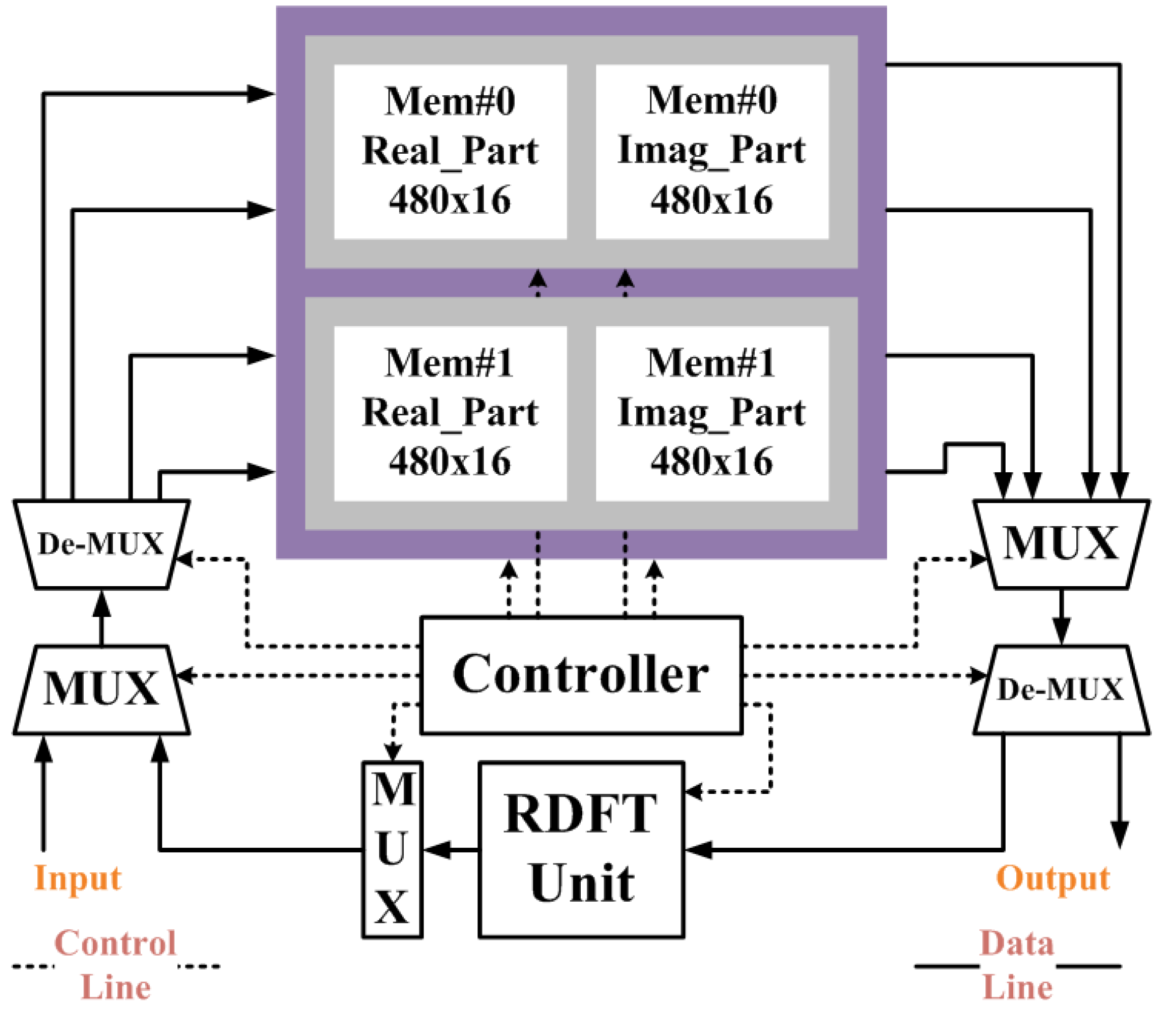
and  can be computed by one multiplication and a simple shift operation. To reduce the usage of multipliers in implementation, a multiplier-sharing scheme is proposed and applied in [23,24,26,29,30,31,32] for this recursive structure. Hence, the multiplication of cosine and sine can be computed by the same multiplier with one clock cycle delay in realization. By adopting the hardware-sharing scheme and register-shifting concept, the RDFT circuit of Lai et al. [29] can be further improved. Figure 1 shows the compact RDFT circuit. The detailed control rules of multiplexers are shown in Figure 1b.
 .
.


 . It implies that the computation between c-point DFT and m-point DFT has a complex multiplication. Additionally, it requires extra adders, multipliers and ROMs for the operations of twiddle factors in implementation. On the other hand, it will also increase the number of multiplications and additions in algorithm. Although the CF-DFT algorithm would take a fewer costs than PF-DFT, it can be applied to compute the one-prime-length DFT coefficients. To reduce the growth of coefficients with the variable-length DFT for DRM specification, Lai et al. proposes a coefficient-free algorithm in [31,32]. The two major coefficients in Equation (2), i.e., and
  , can be respectively calculated by using the trigonometric identities Equations (9,10) [31]. The detailed computations have been introduced in section 2.C of Lai et al.’s paper [31]. It is also applied to generate the coefficients of twiddle factors in this paper. Note that it only takes two computational cycles to generate the twiddle factors by using two multipliers in one RDFT kernel.
3. The Proposed Compact RDFT Architecture Design

4. Low Power VLSI Implementation
4.1. Low-Power Optimizations


4.2. Implementation Results


5. Comparison and Discussion

| Length | 288 | 256 * | 176 | 112 | 27 * | 480 | 60 |
|---|---|---|---|---|---|---|---|
| c | 32 | 16 | 16 | 16 | 9 | 32 | 12 |
| m | 9 | 16 | 11 | 7 | 3 | 15 | 5 |
| A | 9 | 1 | 11 | 7 | 1 | 15 | 5 |
| B | 32 | m | 16 | 16 | m | 32 | 12 |
| C | 64 | c | 144 | 64 | c | 256 | 36 |
| D | 255 | 1 | 33 | 49 | 1 | 255 | 25 |
| Method | Multiplications | Additions | ||
|---|---|---|---|---|
| N = 288 | N = 256 | N = 288 | N = 256 | |
| [26] * | 167,616 | 132,608 | 334,080 | 264,192 |
| [27] | 41,464 | 32,760 | 85,658 | 67,946 |
| [29] | 82,654 | 65,278 | 167,902 | 132,862 |
| [30] | 24,768 | 332,928 | 49,536 | 263,168 |
| [32] | 12,704 | 332,928 | 25,984 | 263,168 |
| Proposed | 11,470 | 8,640 | 22,034 | 14,976 |
| Method | Transform length | ||||
|---|---|---|---|---|---|
| 288 | 256 | 176 | 112 | 27 | |
| [26] | 41,472 | 32,768 | 15,488 | 6,272 | N/A |
| [27] | 431 | 383 | 263 | 167 | N/A |
| [29] | 41,327 | 32,639 | 15,399 | 6,215 | 364 |
| [30] | 9,594 | 32,896 | 3,124 | 1,960 | N/A |
| [32] | 4,842 | 11,137 | 1,594 | 1,006 | N/A |
| Proposed | 6,693 | 5,958 | 2,865 | 1,609 | 346 |
| Method | Multiplier | Adder | Buffer | ROM | DTPT |
|---|---|---|---|---|---|
| [26] | 10 | 17 | No | Yes | 1 |
| [27] | N + 4 | N + 18 | Yes | Yes | 4 |
| [29] | 2 | 13 | No | Yes | 2 |
| [30] | 4 | 8 | Yes | Yes | 1 |
| [32] | 6 | 18 | Yes | No | 4 |
| Proposed | 2 | 4 | No | No | 2 |
| Length | 288 | 256 | 176 | 112 | 27 |
|---|---|---|---|---|---|
| DRM Spec. (ms) | <26.7 | <26.7 | <20 | <16.7 | <2.5 |
| Proposed (us) | 267.72 | 238.32 | 114.60 | 64.36 | 13.84 |
| RAM_ATPT(us) | 23.04 | 20.48 | 14.08 | 8.96 | 2.16 |
| Reduction (%) | 98.91 | 99.03 | 99.36 | 99.56 | 99.36 |


| Design | [29 | [30 | [33] | This work | |
|---|---|---|---|---|---|
| Technology | 0.18 μm | 0.18 μm | 0.18 μm | 0.18 μm | |
| Internal/Coeff. word lengths | 24/24 (bits) | 21/16 (bits) | 24/24 (bits) | 24/24 (bits) | |
| Data Memory (bits) | Excluded | Excluded | Excluded | 2 × 480 × 32 | |
| Coefficient Memory | Excluded | Coeff.-free | Coeff.-free | Coeff.-free | |
| Supply Voltage | 1.98 v | 1.98 v | 1.98 v | 1.7 v (opt.) | |
| Clock Rate | 25 MHz | 25 MHz | 25 MHz | 25 MHz | |
| Supporting DFT | 288, 256, 176, | 288, 256, 176, | 288, 256, 176, | 288, 256, 176, | |
| Transform-Length | 112, 212, 106 | 112 | 112, 480, 60 | 112, 480, 60 | |
| Executing Time for 288-point | 1.65 ms | 384 μs | 193.68 μs | 267.72 μs | |
| Power Consumption | Circuit | 5.98 mW | 8.44 mW | 14.3 mW | 9.62 mW(opt.) |
| Data Memory | 5.53 mW * | 5.53 mW* | 5.53 mW * | ||
| Core Area | Circuit | 0.154 mm2 | 0.265 mm2 | 0.746 mm2 | 0.714 mm2 |
| Data Memory | 0.347 mm2 | 0.347 mm2 | 0.347 mm2 | ||
| Normalized DFTs/Energy | 63.71 | 225.56 | 315.05 | 346.34 (opt.) | |

6. Conclusions
Acknowledgments
References
- Digital Radio Mondiale; System Specification; ES 201 980 V3.1.1; European Telecommunications Standards Institute (ETSI): Nice, France, August 2009.
- Tai, S.C.; Wang, C.C.; Wang, J.L. Circuit-Sharing Design between FFT and IMDCT with Pipeline Structure for DAB Receiver. In Proceedings of the 17th International Conference on Advanced Information Networking and Applications, Xi’an, China, 27–29 March 2003; pp. 768–773.
- Tai, S.C.; Wang, C.C.; Lin, C.Y. FFT and IMDCT circuit sharing in DAB receiver. IEEE Trans. Broadcast. 2003, 49, 124–131. [Google Scholar] [CrossRef]
- Wang, C.C.; Lin, C.Y. An Efficient FFT processor for DAB receiver using circuit-sharing pipeline design. IEEE Trans. Broadcast. 2007, 53, 670–677. [Google Scholar] [CrossRef]
- Kim, B.E.; Chung, J.Y.; Hwang, S.Y. An efficient fixed-point IMDCT algorithm for high-resolution audio appliances. IEEE Trans. Consum. Electron. 2008, 54, 1867–1872. [Google Scholar] [CrossRef]
- Radio Broadcasting System: Digital Audio Broadcasting to Mobile Portable and Fixed Receiver; ETS 300 401; European Telecommunications Standards Institute (ETSI): Nice, France, January 2006.
- Digital Audio Broadcasting (DAB): Transport of Advanced Audio Coding (AAC) Audio; ETSI TS 102 563; European Telecommunications Standards Institute (ETSI): Nice, France, February 2007.
- Lai, S.C.; Lei, S.F.; Luo, C.H. Low-Cost and Shared Architecture Design of Recursive DFT/IDFT/IMDCT Algorithms for Digital Radio Mondiale System. In Proceedings of IEEE International Conference on Intelligent Information Hiding and Multimedia Signal Processing (IIH-MSP-2010), Darmstadt, Germany, 15–17 October 2010; pp. 276–279.
- Chiang, H.C.; Liu, J.C. Regressive implementations for the forward and inverse MDCT in MPEG audio coding. IEEE Signal Process. Lett. 1996, 3, 116–118. [Google Scholar] [CrossRef]
- Nikolajevic, V.; Fettweis, G. Computation of forward and inverse MDCT using Clenshaw’s recurrence formula. IEEE Trans. Signal Process. 2003, 51, 1439–1444. [Google Scholar] [CrossRef]
- Chen, C.G.; Liu, B.D.; Yang, J.F. Recursive architectures for realizing modified discrete cosine transform and its inverse. IEEE Trans. Circuits Syst. II 2003, 50, 28–45. [Google Scholar]
- Nikolajevič, V.; Fettweis, G. New Recursive Algorithms for the Forward and Inverse MDCT. In Proceedings of the IEEE Workshop on Signal Processing Systems: Design and Implementation (SiPS’2001), Antwerp, Belgium, 26–28 September 2001; pp. 51–57.
- Nikolajevič, V.; Fettweis, G. New recursive algorithms for the unified forward and inverse MDCT/MDST. J. VLSI Signal Process. Syst. 2003, 34, 203–208. [Google Scholar] [CrossRef]
- Fox, W.; Carriera, A. Goertzel Implementations of the Forward and Inverse Modified Discrete Cosine Transform. In Proceedings of the IEEE Canadian Conference on Electrical and Computer Engineering (CCECE’2004), Niagara Falls, Canada, 2–5 May 2004; pp. 2371–2374.
- Chen, C.H.; Wu, C.B; Liu, B.D.; Yang, J.F. Recursive Architectures for the Forward and Inverse Modified Discrete Cosine Transform. In Proceedings of the IEEE Workshop on Signal Processing Systems: Design and Implementation (SiPS’2000), Lafayette, LA, USA, 11–13 October 2000; pp. 50–59.
- Cheng, Z.Y.; Chen, C.H.; Liu, B.D.; Yang, J.F. Unified Selectable Fixed-Coefficient Recursive Structures for Computing DCT, IMDCT and Subband Synthesis Filtering. In Proceedings of the IEEE International Symposium on Circuits and Systems, Vancouver, Canada, 23–26 May 2004; pp. 557–560.
- Lei, S.F.; Lai, S.C.; Hwang, Y.T.; Luo, C.H. A High-Precision Algorithm for the Forward and Inverse MDCT Using the Unified Recursive Architecture. In Proceedings of the IEEE International Symposium on Consumer Electronics, Vilamoura, Algarve, 14–16 April 2008; pp. 1–4.
- Lai, S.C.; Lei, S.F.; Luo, C.H. Common architecture design of novel recursive MDCT and IMDCT algorithms for application to AAC, AAC in DRM, and MP3 codecs. IEEE Trans. Circuits Syst. II 2009, 56, 793–797. [Google Scholar] [CrossRef]
- Lei, S.F.; Lai, S.C.; Cheng, P.Y.; Luo, C.H. Low complexity and fast computation for recursive MDCT and IMDCT algorithms. IEEE Trans. Circuits Syst. II 2010, 57, 571–575. [Google Scholar] [CrossRef]
- Wolkotte, P.T.; Smit, G.J.M.; Smit, L.T. Partitioning of a DRM Receiver. In Proceedings of the 9th International OFDM-Workshop, Dresden, Germany, 15–16, September 2004; pp. 299–304.
- Goertzel, G. An algorithm for the evaluation of finite trigonometric series. Am. Math. 1958, 65, 34–35. [Google Scholar] [CrossRef]
- Yang, J.F.; Chen, F.K. Recursive discrete Fourier transform with unified IIR filter stluclures. Signal Process. 2002, 82, 31–41. [Google Scholar] [CrossRef]
- Van, L.D.; Yang, C.C. High-Speed Area-Efficient Recursive DFT/IDFT Architectures. In Proceedings of the IEEE International Symposium Circuits and System, Vancouver, Canada, 23–26 May 2004; pp. 357–360.
- Van, L.D.; Yu, Y.C.; Huang, C.N.; Lin, C.T. Low Computation Cycle and High Speed Recursive DFT/IDFT: VLSI Algorithm and Architecture. In Proceedings of the IEEE Workshop on Signal Processing Systems, Athens, Greece, 2–4 November 2005; pp. 579–584.
- Fan, C.P.; Su, G.A. Efficient recursive discrete Fourier transform design with low round-off error. Int. J. Electr. Eng. 2006, 13, 9–20. [Google Scholar]
- Van, L.D.; Lin, C.T.; Yu, Y.C. VLSI architecture for the low-computation cycle and power-efficient recursive DFT/IDFT design. IEICE Trans. Fundam. Electron. Commun. Comput. Sci. 2007, E90-A, 1644–1652. [Google Scholar]
- Meher, P.K.; Patra, J.C.; Vinod, A.P. Novel Recursive Solution for Area-Time Efficient Systolization of Discrete Fourier Transform. In Proceedings of the IEEE International Symposium on Signals, Circuits and Systems, Lasi, Romania, 12–13 July 2007; pp. 193–196.
- Meher, P.K.; Patra, J.C.; Vinod, A.P. Efficient systolic designs for 1- and 2-dimensional DFT of general transform-lengths for high-speed wireless communication applications. J. Signal Process. Syst. 2010, 60, 1–14. [Google Scholar] [CrossRef]
- Lai, S.C.; Lei, S.F.; Chang, C.L.; Lin, C.C.; Luo, C.H. Low computational complexity, low power, and low area design for the implementation of recursive DFT and IDFT algorithms. IEEE Trans. Circuits Syst. II 2009, 56, 921–925. [Google Scholar] [CrossRef]
- Lai, S.C.; Juang, W.H.; Chang, C.L.; Lin, C.C.; Luo, C.H.; Lei, S.F. Low-computation cycle, power-efficient, and reconfigurable design of recursive DFT for portable digital radio mondiale receiver. IEEE Trans. Circuits Syst. II 2010, 57, 647–651. [Google Scholar] [CrossRef]
- Lai, S.C.; Lei, S.F.; Juang, W.H.; Luo, C.H. A low-cost, low-complexity and memory-free architecture of novel recursive DFT and IDFT algorithms for DTMF application. IEEE Trans. Circuits Syst. II 2010, 57, 711–715. [Google Scholar] [CrossRef]
- Lai, S.C.; Juang, W.H.; Lin, C.C.; Luo, C.H.; Lei, S.F. High-throughput, power-efficient, coefficient-free and reconfigurable green design for recursive DFT in a portable DRM receiver. Int. J. Electr. Eng. 2011, 18, 137–145. [Google Scholar]
- Hsiao, C.F.; Chen, Y.; Lee, C.Y. A generalized mixed-radix algorithm for memory-based FFT processors. IEEE Trans. Circuits Syst. II 2010, 57, 26–30. [Google Scholar] [CrossRef]
- Munch, M.; Wurth, B.; Mehra, R.; Sproch, J.; Wehnl, N. Automating RT-Level Operand Isolation to Minimize Power Consumption in Datapaths. In Proceedings of the IEEE Design Automation and Test, Paris, France, 27–30 March 2000; pp. 624–631.
- Baas, B.M. A low-power, high-performance, 1024-Point FFT processor. IEEE J. Solid-State Circuits 1999, 34, 380–387. [Google Scholar]
© 2013 by the authors; licensee MDPI, Basel, Switzerland. This article is an open access article distributed under the terms and conditions of the Creative Commons Attribution license (http://creativecommons.org/licenses/by/3.0/).
Share and Cite
Lai, S.-C.; Lee, Y.-S.; Lei, S.-F. Low-Power and Optimized VLSI Implementation of Compact Recursive Discrete Fourier Transform (RDFT) Processor for the Computations of DFT and Inverse Modified Cosine Transform (IMDCT) in a Digital Radio Mondiale (DRM) and DRM+ Receiver. J. Low Power Electron. Appl. 2013, 3, 99-113. https://doi.org/10.3390/jlpea3020099
Lai S-C, Lee Y-S, Lei S-F. Low-Power and Optimized VLSI Implementation of Compact Recursive Discrete Fourier Transform (RDFT) Processor for the Computations of DFT and Inverse Modified Cosine Transform (IMDCT) in a Digital Radio Mondiale (DRM) and DRM+ Receiver. Journal of Low Power Electronics and Applications. 2013; 3(2):99-113. https://doi.org/10.3390/jlpea3020099
Chicago/Turabian StyleLai, Shin-Chi, Yueh-Shu Lee, and Sheau-Fang Lei. 2013. "Low-Power and Optimized VLSI Implementation of Compact Recursive Discrete Fourier Transform (RDFT) Processor for the Computations of DFT and Inverse Modified Cosine Transform (IMDCT) in a Digital Radio Mondiale (DRM) and DRM+ Receiver" Journal of Low Power Electronics and Applications 3, no. 2: 99-113. https://doi.org/10.3390/jlpea3020099
APA StyleLai, S.-C., Lee, Y.-S., & Lei, S.-F. (2013). Low-Power and Optimized VLSI Implementation of Compact Recursive Discrete Fourier Transform (RDFT) Processor for the Computations of DFT and Inverse Modified Cosine Transform (IMDCT) in a Digital Radio Mondiale (DRM) and DRM+ Receiver. Journal of Low Power Electronics and Applications, 3(2), 99-113. https://doi.org/10.3390/jlpea3020099