Review

A Review on the Recovery and Separation of Gallium and Indium from Waste

Department of Inorganic Chemistry, Analytical Chemistry and Electrochemistry, Silesian University of Technology, B. Krzywoustego 6, 44-100 Gliwice, Poland
Resources 2024, 13(3), 35; https://doi.org/10.3390/resources13030035
Submission received: 13 December 2023 / Revised: 27 January 2024 / Accepted: 22 February 2024 / Published: 1 March 2024

Abstract

:
Gallium and indium are crucial metals in various industries, such as the medical and telecommunication industries. They can find applications as pure metals, alloys and alloy admixtures, oxides, organometallic compounds, and compounds with elements such as nitrogen or arsenic. Recovery of these two metals from waste is an important issue for two main reasons. First, gallium and indium are scattered in the Earth’s crust and their minerals are too rare to serve as a primary source. Second, e-waste contributes to the rapidly growing problem of Earth littering, as its amount increased significantly in recent years. Therefore, it is essential to develop and implement procedures that will enable the recovery of valuable elements from waste and limit the emission of harmful substances into the environment. This paper discusses technological operations and methods that are currently used or may be used to produce pure gallium and indium or their oxides from waste. The first step was described—waste pretreatment, including disassembly and sorting in several stages. Then, mechanical treatment as well as physical, chemical, and physicochemical separations were discussed. The greatest emphasis was placed on the hydrometallurgical methods of gallium and indium recovery, to be more precise on the extraction and various sorption methods following the leaching stage. Methods of obtaining pure metals or metal oxides and their refining processes were also mentioned.

1. Introduction

Over the past decades, there has been a rapid development of the electronics industry, which continues to this day. Devices such as diodes, integrated circuits, or transmitters have started to accompany us in everyday life in increasing numbers. They provide us with the latest news and entertainment and enable remote work and quick contact with loved ones. We can find them both in the hospital and in our living rooms—or even closer, on the wrist or in the pocket.
Unfortunately, the life of many devices containing electronic circuits is short. This is due not only to the failure rate and difficulty of repair, but also to the very pace at which new models are created. Many people willingly follow the trends and want to be up to date with the latest technologies, which is why they change their devices to newer ones more often than just when the old ones stop fulfilling their functions [1].
The competition between electronics companies has been going on for many years, recently focusing on GPU graphics systems (graphics cards for cryptocurrency mining). The near future is the production of new processors designed specifically to support AI algorithms. We are currently observing a technological trend that allows for the introduction of artificial intelligence everywhere, from consumer processors, through server systems, to dedicated computing systems. Although miniaturized, new processors designed to support AI algorithms contain hundreds, millions, or even billions of electronic components, which are made of semiconductor materials. It can therefore be predicted that soon the earth will be covered with miniaturized e-waste, which will require specialized disposal due to the presence of valuable semiconductor materials such as GaAs or GaN.
In Europe alone, around 10 million tons of WEEE (Waste of Electrical and Electronic Equipment) are produced annually; this accounts for approximately 13% of all municipal waste registered on this continent. It is estimated that the amount of produced WEEE will gradually increase by 3–5% per year in the upcoming years [2]. Data characterizing global WEEE production show similar trends; for example, in 2019 around 53.6 megatons of electronic and electrical waste were produced, and in 2014 around 44.4 megatons. Based on these data, it can be calculated that this amount may increase to 74.7 megatons in 2030 (Figure 1) [3].
Gallium and indium are considered rare metals from a technological point of view. The raising interest in these elements began over a hundred years ago (1920, USSR) when it was announced that, together with germanium, selenium, and tellurium, Ga and In joined a group of rare elements and a dispersed subgroup [2]. Over the past decades, they have gained more and more applications and are now almost an inseparable component of many electrical and electronic devices [4,5,6]. Gallium is crucial to the modern electronic industry, where it is used mainly to manufacture semiconductor materials [7]. The use of pure In has also greatly increased with the use of indium-tin-oxide (ITO) electrode material for liquid crystal display (LCD) panels. A dynamically developing field—just like LED technology—is the production of modern CIGS solar cells (copper indium gallium (di)selenide) [4,5].
Gallium is currently classified as a critical raw material (CRM) and associated with high supply risk. Both gallium and indium are among the 30 critical raw materials (CRMs) on the 2020 EU list; however, indium has been removed from the EU CRM list which was published in 2023. This is because both the supply risk and the economic importance of indium used in flat-panel displays (FPD) dropped below the thresholds and the EU indium production is higher than the EU consumption [8]. On the other hand, new applications of indium are becoming increasingly important. Indium-added pure tin solders may replace lead–tin eutectic solders soon. As is widely known, Pb-Sn alloys pose significant hazards to both the environment and human health due to the toxicity of lead [9,10,11,12].
The provisions of the RoHS directive (Restriction of Hazardous Substances) specify the permissible content of harmful substances (lead, mercury, cadmium, hexavalent chromium, and polybrominated compounds) used by manufacturers in electrical and electronic equipment (EEE). Gallium and indium are not on this list, so their compounds may become substitutes for harmful substances currently used in EEE. Substitution of hazardous substances in EEE should be a priority and carried out in such a way as to be compatible with the health and safety of users of EEE [13].
Due to the increasing demand for gallium and indium caused by the development of the electrical and electronic equipment industry, production needs are growing. As can be seen in Figure 2a, approximately 210 tons of high-purity gallium were produced in 2019. The largest manufacturers were China, Slovakia, Japan, and the United States. The so-called primary gallium, characterized by its lower quality, was produced in the amount of 324 tons, and its main suppliers were the United States, China, Japan, Russia, Ukraine, and Korea. In 2022, the production of refined gallium amounted to 290 tons, which was a 16% increase compared to 250 tons in 2021. This had and still has an impact on the prices: in 2019, a customer had to pay about USD 573 per kilogram of refined gallium and USD 153 for low-purity primary gallium, while in 2022 the gallium price was, respectively, USD 640 and USD 420 per kilogram of high-purity refined gallium and low-purity primary gallium (Figure 2b). As can be seen, the prices across the years for both types of gallium increased, and Canada joined the group of significant producers. In the case of indium, only the data about the production of refined metal are available; in 2019, it amounted to 760 tons, while in 2018 it was 741 tons. In 2021 and 2022, indium production increased to 932 and 900 tons, respectively—see Figure 2c. The main manufacturers of indium are China, Peru, Korea, Canada, and Japan. Figure 2d shows that prices of indium have not changed significantly over the previous years. In 2018, a customer had to pay USD 310 per kilogram of indium, in 2019—USD 390, and in 2020—USD 395. This is presumably related to the existing effective substitutes for ITO in the strategic application fields of indium [7,14,15,16].
Gallium comes primarily from the processing of bauxite and zinc ores, while the main primary source of indium is actually ores containing zinc sulfides. Production of gallium and indium from ores is only a side process and benefit, and the amount obtained depends largely on the demand for the main products (e.g., zinc) [16].
Some amounts of these metals come from the recycling of used equipment, which is carried out mainly in Canada, the United States, Korea, and Japan [14]. In the case of gallium, substantial quantities of new scrap, generated during the manufacture of GaAs-based devices, are reprocessed to recover high-purity gallium at only one facility in New York [16]. Most of the indium is recovered from ITO scrap in Japan and Korea [7]. However, this amount is certainly not sufficient and is related to the fact that only about 20% of all discarded electronics are properly recycled through organized and regulated channels. Even in the EU, which is a global leader in e-waste recycling, only 35 percent of e-waste is reported as properly managed and recycled. It is not entirely clear what happens to the remaining 80% of indium—its fate depends primarily on the country in which it found itself. In very highly developed countries, probably 8% of it ends up in landfills or is incinerated. Most of it is mixed with other waste and subjected to incomplete recycling, during which appropriate conditions are not provided for the recovery of valuable materials. The rest, on the other hand, is either refurbished and found a new life in less developed countries, or illegally smuggled under the guise of becoming scrap (it is estimated that around 7–20% of WEEE is smuggled). In middle- and low-income countries, the situation is much worse. Those countries either do not yet have a fully developed system for managing this waste, or there is no such system at all, and e-waste is managed by the informal sector. Therefore, it is very often processed in inappropriate conditions, which causes serious damage to the health of not only the employees themselves but also people (mainly children) living in the vicinity of such processing plants. Of course, incorrect handling of WEEE also threatens the environment due to the numerous hazardous substances it contains [3]. It is also worth noting that the Basel Convention recognizes most electronics as hazardous waste [2].
In addition to the benefits that recycling will bring to the planet and the health of its inhabitants, economics also come into play. It is estimated that the value of all materials recovered from WEEE in 2019 was approximately USD 10 trillion, and the natural resources available to us are depleting [3]. The amount of gallium in all known bauxite deposits is estimated to be at 1 megaton; however, less than 10% of gallium in the bauxite and zinc resources is considered to be potentially recoverable [16]. The above-mentioned facts encourage the improvement of gallium and indium recovery methods from waste and the implementation of appropriate procedures of recycling.
This work aims to present a comprehensive overview of the state-of-the-art references in the field of gallium and indium recovery from secondary resources. It reviews the scientific knowledge about methods of waste pretreatment (dismantling, sorting, crushing, and roasting), followed by hydrometallurgical techniques (leaching, extraction, ion exchange, sorption, and precipitation), and finally focusing on the production of pure metals or their oxides. Additionally, the work includes a discussion on assisted methods for leaching and separating gallium and indium from each other and other metals which distinguishes this review paper from others. An advantage and novelty of this study is a suggestion of research areas that require intensified scientific activities at the present time.

2. Primary and Secondary Sources of Gallium and Indium

In obtaining gallium from its natural sources, the Bayer process currently has the largest importance. The main purpose of this process is to produce metallic aluminum from bauxite, while gallium is one of the by-products, forming an insoluble precipitate called “red mud”. It is separated from the mixture by subjecting the sludge to two electrolysis processes. The first one, using a mercury cathode, aims to concentrate the mixture. During the second one, using a stainless-steel cathode, gallium is obtained. It is most often subjected to further processing and purification, including the use of high temperatures, acids, and oxygen [17]. The second primary source is the process of hydrometallurgical treatment of zinc ores, in which gallium, along with several other elements, is again only an additional benefit and not the main product. It is also obtained through the electrolysis of the process residues, which is preceded by a series of steps aimed at removing or masking the elements present in the solution (cadmium, copper, iron, aluminum, germanium, and others). Depending on the method used, these stages may include, among others: leaching, precipitation, filtration, acidification, ion exchange, or extraction [18,19,20]. On a smaller scale, gallium is also obtained from coal ashes [7].
Secondary sources of gallium consist primarily of electronics: all kinds of damaged and used equipment, such as smartphones, TV sets, microwave ovens, computers, and laptops, as well as thermometers, diodes, and plates. As can be seen in Figure 3, approximately 54 megatons of WEEE are produced annually. Asia (24.9 megatons and 5.6 kg per person), the Americas (13.1 megatons and 13.3 kg per person), and Europe (12 megatons and 16.2 kg per person) lead the way in waste production. It is worth noting that in Europe about 42.5% of this waste is appropriately recycled, in Asia 11.7%, and in both of the Americas, only 9.4% [3].
It is estimated that in recent years “large equipment” used all over the world, i.e., mainly household appliances, accounted for approximately 24.5% of WEEE—see Figure 4. Another 32.4% was “small equipment”, which included both small household appliances (e.g., vacuum cleaners and fans) and electronics not included in the IT and telecommunication category (e.g., cameras). Waste from the IT and communication category, the share of which amounted to 8.7%, was mainly smartphones, computer parts, and devices equipped with transmitters (usually of the newer generation). Among them, pen drives, CDs, and portable memory devices could also be found. Lamps and light bulbs accounted for about 1.7%, while screens and monitors accounted for 12.5%. A category generally called “heat exchangers”, which includes, among others, thermometers, air conditioners, refrigerators, and freezers, consisted of 20.2%. In all categories, except for “screens and monitors”, there was an increase in percentage of content compared to the previous year. The number of used screens and monitors decreased by 1%, but only seemingly; the number of components continues to grow, but the new screens are getting lighter [3].
About 95% of indium manufactured from natural sources is a byproduct of obtaining zinc from minerals containing it (mainly sulfides). The remaining 5% comes mainly from the processes of obtaining copper and tin, but the production of other base metals, such as iron or lead, also has a small part [17].
Indium is obtained from zinc smelting residues, dusts, slags, and exhaust fumes, in refineries specially adapted for this purpose, which can operate independently or be located on the premises of smelters. In the hydrometallurgical process, after sphalerite has been roasted and subjected to a calcination step, deposits of zinc-related elements are precipitated in the elemental ore. Among them is indium. The precipitate, which is one of these residues, is then subjected to a series of technological operations, including numerous washings with acids and bases, manipulation of the pH of the solution, precipitation, filtration, and cementation, during which the individual components are separated. The finally obtained indium cement is burned in a kiln in the presence of chlorides, which allows for the production of ingots of this metal [18].
Secondary sources of indium are used electronic devices, especially those equipped with screens: TV sets, monitors, telephones, electronic billboards, interactive boards, tablets, and laptops. Other important sources are photovoltaic cells and car windows.
Economically viable secondary sources of indium include those that can be easily extracted; these are primarily screens and monitors as well as lamps and light bulbs, which can be amounted to a total of about 7.6 megatons (only in 2019) of potential secondary raw material for recycling processes.

3. Methods of Recovering Gallium and Indium from Secondary Sources

The main methods of metal recovery include pyrometallurgical and hydrometallurgical ones, which are used after the process of pretreatment of waste materials. These techniques are based on the use of various physicochemical properties of metals, and their effective application often requires very specific operating conditions. Hydrometallurgical methods are more popular than pyrometallurgical ones due to the milder conditions in which they are carried out, as well as a wide range of reagents available on the market. These methods are also used to recover gallium and indium from waste electrical and electronic equipment. Figure 5 shows a general scheme of five steps of metal recovery from waste.

3.1. Waste Pretreatment

The waste is pretreated before appropriate methods are used to recover gallium and indium. Pretreatment usually consists of several steps and depends on the type of waste, the availability of reagents, and what the further treatment will look like; therefore, individual recycling plants do not use all the steps mentioned later in the chapter.
WEEE is a material with a very complex composition, which therefore requires costly and time-consuming treatment. However, it is a necessary process because it simplifies the composition of the material directed to further stages of recycling [21].

3.1.1. Disassembly and Sorting

This stage allows for the separation of elements containing hazardous substances and other compounds, which are included in Annex VII of Directive 2012/19/EU. Batteries, external electrical wiring, bromine-containing plastics, mercury-containing backlights, printed circuit boards, and liquid crystal displays are listed there [22].
However, dismantling is not only conducted to meet the EU requirements. It is usually focused on extracting the most valuable materials from the waste, such as processors or RAM. The separation of elements containing valuable metals from plastic and ceramics and their segregation significantly improves the efficiency of the recycling process and makes it more economical [21].
Disassembly is carried out manually or with a special machine, with the first method being better in terms of efficiency, price, and the initial condition of the item. Despite this, some companies have already opted for automated systems, now using circular saws, lasers, or even water-jet cutting. Research is also underway to improve their operations [22].
Sorting usually consists of dividing elements into groups with similar physical properties, such as density, mass, shape, and magnetic and electrical properties [21].
After dismantling and assigning the elements to appropriate groups, the composition of the mixture they form is usually further simplified. This is accomplished both with further mechanical disassembly of the elements and by subjecting them to various types of physical and chemical separation techniques [23].
For example, in the case of LCD panels, the polarizing film and liquid crystal are removed, leaving only the ITO coating. This is achieved in various ways. The material can be pyrolyzed in a nitrogen atmosphere or vacuum, which will lead to the incineration of the organic components of the panels and allow for the obtainment of purified ITO glass. A physicochemical method is also used, which is more ecological and easier to use than pyrolysis. The panels are heated to about 230–240 °C which causes most of the foil to peel off, and the residues are easy to remove with a brush. The glass is then crushed and subjected to washing with acetone while treating it with ultrasound to remove the liquid crystal. On the other hand, the process of so-called electrical disintegration uses high current. It is the most environmentally friendly of the mentioned methods; moreover, it allows for the obtainment of glass from the ITO without the need to crush it, thus avoiding the accompanying losses [23].
Another example of research aimed at increasing the recycling efficiency is a system to sort electronic components from printed circuit boards (PCBs) via elemental composition. Current methods of treating waste PCBs (WPCBs), which consist first of crushing and then of grinding, produce a powder with a highly complex and heterogeneous chemical composition. The new method should allow for sorting wastes according to their chemical composition, leading to an enrichment of many targeted elements. It combines a convolutional-neural-network-based optical recognition with multienergy X-ray transmission spectroscopy, demonstrating up to 96.9% accuracy in controlled conditions. Hence, with the elemental enrichments of up to 10,000 for targeted elements, this method renders economically viable recovery of previously unrecycled critical metals by enriching sorting groups in many important metals [24].

3.1.2. Mechanical and Physical Processing

Mechanical treatment mainly involves various types of crushing and grinding processes, the aim of which is to homogenize the mixture and obtain grains of the appropriate size.
WEEE is crushed, most often while using shredders and hammer mills. The degree of fragmentation that must be achieved depends strictly on the future fate of the material: hydrometallurgical processes require fine grains (<200 μm), while pyrometallurgical processes also work well when the substrate is relatively coarse-grained [21].
At this stage, again, there may be many differences between the methods, even if they concern the same electronic items. An example could again be LCD panels. After the previously described preliminary processing, the obtained material is ground in ball mills, because the research has shown that the small grain size has a positive effect on the efficiency of the acid mixture washing process (grains below 5 mm allow for washing of up to 92% of indium). As already mentioned, crushing and grinding always involve some losses, which is why solutions are sought to minimize them. The HEBM method, which requires precise removal of the polarizing foil and liquid crystal, uses a high-energy ball mill. The obtained grains have a size of approximately 1 μm. The grinding time is about a minute, which is much less than in the case of classic grinding, which usually takes up to 6 h. In addition to saving time, this method also provides increased efficiency: during a test, it allowed 86% of indium to be washed from the material, while traditionally ground material subjected to the same solution released only 76.4% of the indium contained in it [23].
The fragmentation of the material also allows it to be subjected to a physical separation aimed at enriching it with the ingredients (of course, if it is predicted in a specific method). These separations are eagerly used due to their simplicity and low costs, and their effectiveness is often closely related to the level of material fragmentation. They use differences in various properties of the substances included in each mixture, such as relative density, conductivity, magnetic susceptibility, wettability, and brittleness, to separate them [25].
The five most often used operations are the following: flotation, magnetic separation, electrostatic separation, eddy current separation, and gravity separation. Magnetic separation, which is usually performed first, separates the ferrous metals from the rest of the material using magnetic drum separators. The lightest components of the mixture, such as plastic, can be separated in air classifiers. Their operation is based on a simple principle: air is passed into a chamber of the apparatus from the bottom, into which the shredded material is also introduced. The air lifts the lightest ingredients, and the heavier grains sink lower. Nonferrous metals are separated by considering their conductivity-to-density ratio. Metals with a high value of this ratio (e.g., aluminum, copper, and zinc) are separated via eddy current. Other nonferrous metals are separated electrostatically or using permanent magnets [21,25,26].
Gravity separation can have various technical solutions, but the main feature used in the process is always the difference between relative densities of the components. It can be performed, for example, on shaking tables or through separation in a heavy medium, which involves the use of a liquid of appropriately selected density for separation, in which some of the ingredients sink to the bottom and some come up to the surface [21,27].
Flotation takes advantage of the differences in wettability. It is conducted in a tank called a floating machine filled with liquid (usually water). Air is passed through the system and the flotation reagents are added to facilitate the flotation process. Hydrophobic ingredients are surrounded by gas bubbles and brought to the surface, where they form a mineral foam. The foam, along with valuable ingredients, is collected and directed to settling tanks, while the rest remains at the bottom of the tank and is then removed as sludge [25,28].
All the above-mentioned processes require crushed material, but in the case of magnetic, electrostatic, and eddy current separation, it cannot be too fine because the methods become difficult to carry out and ineffective. During grinding, a certain amount of dust fraction is always created, the presence of which can generate extremely high metal losses, ranging from 10% to even 35%. The other two described methods enable the recovery of metals from such small fractions [21].

3.2. Leaching

Leaching is the first stage of hydrometallurgical treatment used in the processing of low-grade raw materials and WEEE. It involves transferring metals into solutions using appropriate chemical reagents. The type of reagent used in a specific case depends strongly on the chosen method of separating metals from the solution; however, its availability and price should also be considered. Additionally, it is necessary to know which gallium and indium compounds dominate in each material, because some of them may react reluctantly with a given solution, which will reduce the efficiency of the leaching process and result in losses.
In 2019, in the United States, as much as 81% of gallium was used to produce gallium arsenide, gallium nitride, and gallium phosphide [14]. Gallium arsenide is by far the most in-demand product; in recent years, it accounted for up to 95% of the annual global consumption of gallium [16].
The reagent most often used for leaching gallium from GaAs is nitric acid because it yields the best results. The efficiency of the process depends on the concentration, temperature, solid-to-liquid phase ratio (S/L), and leaching time. With various combinations, it is possible to achieve up to 98–99% leaching efficiency [21,22,29].
Leaching is carried out in reactors equipped with a stirrer, usually at normal pressure. After the process is completed, the mixture is filtered, solid residues are separated, and the filtrate containing gallium ions is sent for further processing [29].
The form in which Ga3+ ions appear in the solution depends on the pH and other components present in the solution. Figure 6 shows the speciation of Ga(III) as affected by pH, calculated using the data generated in Li et al.’s study [30]. The dominant species of soluble Ga(III) is Ga3+ at pH < 3.0. In the pH range of 2–8, the species of cations Ga(OH)2+ and Ga(OH)2+ and neutral Ga(OH)3 are present. When the pH is above 8, Ga speciation is strongly dominated by the negatively charged species, Ga (OH)4. However, the research has shown that in the case of supersaturated and concentrated Ga(NO3)3 solutions, the vast majority of gallium ions will occur in the form of ion pairs separated via solvation: Ga(H2O)6NO32+. However, a small amount of bound ion pairs can also be found: Ga(H2O)5ONO22+ [31].
GaN is much more chemically resistant than GaAs. At atmospheric pressure, in the temperature range from 25 °C to 90 °C, the highest leaching efficiency achieved does not exceed 10%. Of all the tested acids, hydrochloric acid turned out to be the best, reaching 8.9% leaching efficiency at 90 °C, while sulfuric acid, nitric acid, and hydrofluoric acid did not even exceed 4%. Effective transfer of gallium from GaN into solution can be achieved using a high pressure. An HCl solution is used for washing, with a concentration of 0.25 M. The ratio of the S/L phase is 1 g/30 cm3, the pressure is 15 atm, and the temperature is 200 °C. With this method, the achieved leaching efficiency can be around 98% [32].
Other methods have proposed roasting Ga-containing materials with hydroxides or basic salts such as LiBO2, NaOH, and Na2CO3, as a prewashing step. The salts are mixed with the ground waste in a mass ratio of 10:1. Roasting is usually carried out for about 8 h at a temperature of about 1000 °C [32,33]. The salts react with GaN, resulting in compounds that can react more easily with the above-mentioned acids. In addition, a certain amount of the compound also reacts with oxygen. For example, during roasting with Na2CO3, the reactions presented in equations 1, 2, 3, and 4 occur [33].
4GaN(s) + 3O2(g) → 2Ga2O3 + 2N2,
2Na2CO3(s) → 2Na2O + 2CO2,
4GaN(s) + 2Na2O + 3O2(g) → 4NaGaO2 + 2N2,
4GaN(s) + 2Na2CO3(s) + 3O2(g) → 4NaGaO2 + 2N2 + 2CO2.
After roasting, a washing step is carried out. Studies have shown that the best washing efficiency (73.3%) is obtained while using NaOH and HCl [32]. Nevertheless, one of the developed methods, focusing on GaN contained in LEDs, uses Na2CO3. It is based on a double washing process: prewashing and washing after incandescence. Each time it is done at 100 °C, using HCl at a concentration of 4 M. After the first washing, the dust is dried and mixed in a 1:1 mass ratio with Na2CO3, then ground in a ball mill all day and dried and heated at 1000 °C for 4 h. After the second washing, the solid phase is filtered from the mixture. The filtrate is mixed with the one from the first leaching and directed for further processing, while the precipitate is analyzed to check the amount of gallium remaining in it. If the content turns out to be significant, it is returned to the process and, together with a new portion of material, introduced to the ball mill once again [33].
In a study documented in reference [34], CIGS materials were treated through a roasting process, which facilitates a transformation of selenides to oxides and a volatilization of Se. Afterward, a hydrochloric acid solution was utilized to leach the oxides in the experiments. The optimal leaching conditions consisted of an acid concentration of 4 mol/dm3, a temperature of 80 °C, a leaching time of 3 h, and an S/L phase ratio of 1 g/10 cm3. The leaching rates of Cu, In, and Ga were 99.98%, 93.40%, and 96.86%, respectively.
One way to transform the elements in spent CIGS into complex selenides is through an oxidative leaching process using nitric acid solution, during which separation of indium can be achieved. After leaching, copper, gallium, and selenium can be completely recovered from the solution by using magnesium oxide as a precipitant. The residue and precipitates can then be heated to 800 °C for 90 min to separate selenium. The recovery efficiencies of copper, indium, gallium, and selenium are high, at 99.23%, 96.82%, 98.08%, and 96.38%, respectively [35].
In solutions containing SO42− ions, gallium may occur in the following forms: GaSO4+ and Ga(SO4)2, with the former dominating when the acid concentration in the solution is low. In the hydrochloric acid solutions, gallium can be found in the form of GaCl2+, GaCl2+, GaCl3, and GaCl4, where the last form dominates in the concentrated acid solutions [31]. The spent GZO and IGZO targets were leached with three kinds of inorganic acids. The highest leaching efficiency using H2SO4 only reaches 85%, while the efficiency using HCl can be 99.34%, but it takes 6 h to leach the material. HNO3, as the leaching agent, has the highest leaching efficiency for a reaction time of 2 h. Under optimal conditions, a leaching efficiency of over 99% can be achieved for indium, gallium, and copper [36].
In the case of indium, most of the annual consumption for several years has been attributed to the production of ITO [4]; therefore, most attention will be given to it. Indium occurs primarily in the form of In2O3, and tin as SnO2. Because tin dioxide reacts reluctantly with acids, Equation (5), together with Equation (6), will constitute the two leading reactions of the indium leaching process with acid solutions [27].
In2O3 + 6H+ → 2In3+ + 3H2O,
SnO + 2H+ → Sn2+ + H2O.
The leaching efficiency is influenced by many factors, such as: grain size, temperature, acid concentration, and S/L ratio. Pulp density is also important, and its increase causes a decrease in the leaching efficiency. Research shows that the optimal temperature for the process ranges from 80 °C to 90 °C [21]. Various types of mineral acids and their mixtures are used to leach indium from ITO. The most popular ones are sulfuric acid and hydrochloric acid, although sometimes nitric acid is also used [23,24,29,31,32,33,37]. Much depends on the way the material is previously processed. Hydrochloric acid has many benefits: a high value of the dissociation constant, high reactivity, thanks to which it easily dissolves many different compounds, and its use does not generate problematic waste (wastewater is neutralized with sodium hydroxide, which leads to the production of sodium chloride) [38]. Moreover, it has a lower tendency to leach toxic components of the material, such as arsenic and antimony [23]. However, it is very corrosive and requires equipment resistant to its corrosive properties [37]. The use of hydrochloric acid at a concentration of 3.2 M allows for the obtainment of a leaching efficiency of 90% [23]. It is possible to obtain higher yields with lower concentrations of hydrochloric acid; however, at elevated temperatures a recovery efficiency of >90% can be achieved with 0.5 M HCl at 80 °C or 2 M HCl at 55 °C [39].
According to the research, using sulfuric acid can result in a similar performance as other options, while also being less expensive and less dangerous to the equipment [40]. A study found that a 0.25 M solution of H2SO4 was the most effective leaching agent for relatively fast reactions and high selectivity, with a recovery efficiency of over 99% for indium from ITO layers. At the same time, more than 95% of the tin remained in a solid residue [41].
Nitric acid is the most expensive of these three acids, so its application is reduced as much as possible [23]. Many different mixtures can be used to achieve high efficiencies. They are not limited to just the three acids mentioned above; they may also contain various other compounds, such as hydrogen peroxide. For example, a mixture containing 90% of 5 M HCl and 10% of hydrogen peroxide (by volume), at 75 °C, at atmospheric pressure, with an S/L phase ratio of 500 g/dm3 and a contact time of 2 h, allows for the obtainment of a solution in which the indium concentration will be around 76 mg/dm3 [38]. An oxidizing mixture of H2SO4 and H2O2 can be used to recycle waste containing InP. This process involves using an oxidizing mixture of H2SO4 and H2O2. When the mixture comes into contact with InP, it causes the phosphorus to oxidize to the valence state of +5, forming a stable H3PO4. Meanwhile, indium is dissolved and becomes soluble in the solution. It has been found that under optimized conditions—which consist of an H2SO4 concentration of 3 mol/dm3, an H2O2/InP mole ratio of 4, an S/L phase ratio of 1:4, a temperature of 80 °C, and a reaction time of 3 h—the leaching efficiency for indium can reach over 99% [42].
It is also possible to improve the washing process by using ultrasound, increased pressure, and mixing [38,43]. The technique of ultrasonic washing has gained importance in previous years [44]. Zhang et al. [45] investigated the recovery of In from LCD waste using HCl leaching and ultrasonication without the need to perform the primary crushing of the material. At low HCl concentrations, and without extra heating, a leaching efficiency of 96.80% for In can be achieved. Souada et al. [46] also used ultrasound in the process of indium leaching with H2SO4 from the end-of-life LCDs, obtaining an In leaching efficiency of 92% after 20 min, which was higher than the leaching efficiency of 70% without the ultrasound. An additional improvement is the use of UAL and supported liquid membrane (SLM) extraction. The leaching efficiency and purity of indium were approximately 97% and 94%, respectively, when using a 0.75 M sulfuric acid solution and 300 W ultrasound power in the experiments [47]. Furthermore, the leaching efficiency for In from the secondary sources is improved when sonication is combined with microwaves. Zhang et al. [48] explored the recovery of In from waste LCDs using different inorganic acids (HCl, H3PO4, and HClO4) in a new microwave–ultrasound heating system. It was found that HCl was the most effective leaching agent and the leaching efficiency for In reached 100%.
The form of In3+ ions in the solution also depends on its pH and other components present in it. Figure 7a shows the speciation of In(III) as affected by pH calculated using the data generated in Ashworth’s doctoral thesis [49]. The dominant species of soluble In(III) is In3+ at a pH < 4.0. In the pH range of 2–7, the species of cations In(OH)2+ and In(OH)2+ exist while neutral In(OH)3 is present in the pH range of 3.5–11.5. When the pH is above 10, In speciation is strongly dominated by the negatively charged species, In(OH)4. In hydrochloric acid solutions, they take the form of [InCln(H2O)6−n]3−n, where n depends on the concentration of the solution and can have a value from 0 to 6. In the diluted solutions, the form with n = 2 dominates, simplifying InCl2+—see Figure 7b [50]. In the solutions where the concentration of the acid is from 1 M to 12 M, the forms with n = 3 and n = 4 (InCl3 and InCl4, respectively) are the most apparent. In the sulfuric acid solutions, indium ions are mainly found in the forms of InSO4+, In(SO4)2, and In(SO4)33– for low, medium, and high acid concentration, respectively (Figure 7c) [50]. In the dilute solutions of nitric acid, the InNO32+ form dominates, while the In(NO3)2+ form is more common in the solutions with acid concentrations ranging from 1 M to 3 M [31].
The recovery of gallium and indium present together in white LED bulbs, also containing significant quantities of Cu, Sn, Pb, and Al, was successfully carried out using nitric acid. Using a 4 M solution of HNO3 at 80 °C with a L/S ratio of 10 caused Cu, Fe, Pb, and Ag to be washed from the waste, while Al passivated and Sn precipitated. After filtration, the LED beads, Al scrap, and Sn(OH)4 precipitate can be separated via three-stage sieving. The LED balls separated on a 2 mm sieve were then leached with HNO3 and ground in a mortar to an average grain size of 250–750 μm. Roasting was then carried out to convert GaN and InN into their leachable forms, according to Reaction (1) for GaN and to Reaction (7) for InN:
4InN(s) + 3O2(g) → 2In2O3 + 2N2
Application of an alkaline fusion with NaOH or roasting with Na2CO3 yielded recovery efficiencies above 90%. Then, the leaching of the roasted material with a 6 M solution of NaOH (L/S ratio of 1) at 95 °C for 3 h can efficiently dissolve Ga, while In is dissolved in the next step with the more concentrated NaOH (10–11 M) [51]. A comparison of the most favorable conditions for the leaching of indium from e-waste is presented in Table 1.
Gallium-based liquid metal (G-LM) waste was leached with a 3 M solution of HNO3 for 2 h at 40 °C and an S/L ratio of 1 g/20 cm3. Under the optimal conditions, more than 99.99% of Ga, In, and Zn were leached and then adsorbed and eluted with a CL-P204 solvent-impregnated resin [52].
It is possible to use mild leaching conditions to recover mainly silver and indium from flexible CIGS solar cells. The results show an increase in the leaching efficiency for Ag and In when acid concentration and a material surface-area-to-liquid ratio (A/L) increase. However, attention should be drawn to the fact that a level of contaminants (from other industrial elements) in the after-leaching solutions is also increasing [52]. The solution to this may be selective leaching of elements, aiming to clean the streams of metals and thus reusing them in new products. Total Ag recovery and 85% recovery efficiency for In can be obtained using 2 M HNO3 and an A/L ratio of 1:3 cm2/cm3 after 24 h of leaching at room temperature. Under the same conditions, leaching with 0.5 M HNO3 recovers 85% of Ag and 30% of In, but correspondingly reduced impurity levels are achieved. Finally, leaching with 0.1 M HNO3 can achieve higher Ag purity in the initial Zn selective leaching step for 1 h [53].
Selectively recovering Ga from gallium-bearing waste (MOCVD waste) of the LED industry by using an oxidation process coupled with NaOH leaching is another innovative and green recycling technology. In the process, GaN and In are converted to alkali-soluble Ga2O3 and alkali-insoluble In2O3 via oxidation calcination. Via the selective leaching with NaOH solution under the conditions of 2 mol/dm3 NaOH, an S/L ratio of 50 g/dm3, a leaching temperature of 90 °C and a leaching time of 180 min, nearly 92.65% of Ga can be recovered with a leaching selectivity of 99.3%. As a result, Ga2O3 with a purity of 99.97% can be obtained from the solution [54].
Some combinations of mixtures for the leaching and the additional treatment, that provide the best results, are listed in Table 2.
New methods of leaching gallium and indium are still being sought out. One of them is a method using tribromide ionic liquids, which allows for an effective transfer of metals from materials containing GaAs and InAs into a solution. However, due to its special nature and the fact that an aqueous solution suitable for typical isolation is not obtained, it will be treated separately and described in more detail later in this work [55].
Another solution is bioleaching, which involves using bacterial cultures. Bioleaching of indium in the presence of tin from LCD panels was carried out with different final efficiencies depending on the LCD pulp density (1% and 2% w/v) and the use of pure or mixed bacteria. By using the mixed culture of Acidithiobacillus ferrooxidans and Acidithiobacillus thiooxidans, high leaching efficiencies of both indium (94.7%) and tin (98.2%) can be obtained [56]. Bio-acid leaching of LED with a high pulp density (40 g/dm3) using only a culture of sulfur-oxidizing bacteria (Acidithiobacillus thiooxidans) but with a multistep contact bioleaching, allowed for the achievement of 100%, 100%, and 75% extraction efficiencies of Cu, Ni, and Ga, respectively [57]. Indium extraction from spent LED monitors, including bioleaching followed by solvent extraction, stripping, and precipitation, was also possible. At optimized inoculum percentages of A. ferrooxidans and A. thiooxidans (respectively, 1.5 and 0.5%, v/v) and pulp density (60 g/dm3) at an initial pH of 2, approximately 100% of indium can be recovered in 18 days [58].

3.3. Solvent Extraction

Extraction is one of the most used methods for separating gallium and indium from solutions. The basis of the process is the selective solubility of the ingredients in an extractant, i.e., an organic solvent. It can occur both in a liquid–solid system and a liquid–liquid system, but in the case of extraction of gallium and indium, the separation of these metals from solutions is used. There are many reagents available on the market suitable for this purpose. The decisive factor in the selection of the extractant is its insolubility or very poor solubility in the solution used for the separation. Moreover, temperature, concentration of a diffusing component, and mixing are of great importance for the extraction efficiency, as they increase the contact surface between the phases and accelerate the diffusion process of the chosen component [23,59].
The efficiency of the gallium and indium extraction process is also influenced by other factors that should be considered when selecting the extractant and setting the parameters under which the process will be carried out. For example, the presence of other metals in the solution is of great importance. It is essential to use an extractant to which the accompanying metals have the lowest possible affinity so that the minimum amount can pass to the extractant, and that they are relatively easy to remove. Moreover, the choice of reagents also depends on the acid used in the earlier step (or acids, if a mixture of them was used) [32] and on the pH [21], because they affect the form in which gallium and indium are present in the solution, and not every form has an equally high affinity for the given extracting solvent [37]. The contact time between the phases is also important, and in some cases the level of pressure also plays a role [60].

3.3.1. Extraction of Ga

Gallium extraction from mixtures containing concentrated acids is very efficient when a mixture of trialkylphosphine oxides, known under the trade name Cyanex 923, is used as the extractant, to which bis-(2,4,4-trimethylpentyl)octylphosphine oxide (with the trade name Cyanex 925) is added [61].
At higher pH values (approximately 2–4), gallium extraction is almost quantitative when carried out using the following substances: 2-ethylhexylphosphonic acid 2-ethylhexyl alcohol ester (EHEHPA), PC 88A), di-(2-ethylhexyl) acid phosphoric acid (D2EHPA), di-(2,4,4′-trimethylpentyl)phosphinic acid (DTMPPA), and derivatives of 2-methyl-8-quinolinol and a mixture of 5-dodecyl salicylic aldehyde oxime and 2-hydroxy-5-nonylacetophenone oxime (LIX 973N) [40,62,63,64].
If the pH of the solution is more alkaline, high process efficiency is ensured using primary amines or a mixture known under the trade name Cyanex 921 as extractants, the main active ingredient of which is trioctylphosphine oxide [31].
Gallium very often occurs in the company of Al(III), Cu(II), and Zn(II). In the solutions, Ni(II) and Fe(III) ions, as well as In(III), very often can be found [65]. However, the separation of gallium and indium will be discussed later in the chapter.
Since the need to take into account the influence of so many factors generates a large number of “combinations” in the solutions after leaching, an example will be presented of the selective extraction of gallium from solutions of hydrochloric acid of various concentrations and with different accompanying metals.
If, in a solution in which the HCl concentration is 5 M, gallium(III) is present in the company of zinc(II) and copper(II), Cyanex 923 and Cyanex 925 will work great as the selective extractants. Their biggest advantage is the fact that small amounts of zinc and copper, which will also pass with gallium into the extractant, can be easily washed out with distilled water. Gallium is removed from the extractant during a solvent regeneration step using an HCl solution [31]. CIGS wastes are materials considered as a viable source for the recovery of Cu, In, Ga, and Se. Using 4 M hydrochloric acid, Cu, In, and Ga can be leached with efficiencies around 99.98%, 93.40%, and 96.86%, respectively. Then, In and Ga can be sequentially extracted using P204, while Cu remains in the solution. Through solvent extraction, the extraction efficiency for In can reach 99.92%, and that of Ga can exceed 99.34% [34].

3.3.2. Extraction of In

In the case of indium, many different types of extractants are currently used to extract indium from solutions. One of the most popular is D2EHPA. It is valued for its high selectivity towards indium in the presence of other ions such as Zn(II), Fe(II), Cd(II), As(III), and Cu(II). In solutions with a low acid concentration, extraction is the most efficient for HNO3 as the leaching agent, followed by H2SO4, while the lowest efficiency is when the acid was HCl. However, this relationship reverses with an increase in the concentration of the given acid due to the change in the dominant form of indium in the solution [37]. If Fe(III) ions are present in the solution, it is necessary to reduce them to Fe(II) before the extraction process [66]. However, D2EHPA is not suitable for the selective extraction of indium from a solution that also contains tin, for example from ITO leaching. Tin passes into the extractant together with indium and it is necessary to separate it with tributyl phosphate (TBP). Another effective method to separate indium and tin is to wash indium away from the extractant with an HCl solution. Many studies have also been carried out on the extraction of metals from solutions after leaching of ITO with a mixture of D2EHPA and TBP, but they usually show greater selectivity towards tin. The developed extraction method enables the separation of tin from the solution using such a mixture or TBP alone, while indium remains in the raffinate [31,37].
Indium that was dissolved in the bioleaching process was extracted using an organic solvent containing 20% (v/v) of D2EHPA in kerosene. To selectively recover indium instead of iron, a stripping step was performed after extraction. The optimal volume ratio of the aqueous to organic phase was found to be 1:1 and the ideal time was determined to be 30 min, resulting in a 91.5% recovery efficiency for indium. The use of a 5 M sulfuric acid solution also proved to be effective in the stripping process. Finally, sodium hydroxide was added to precipitate the indium, resulting in a final precipitate containing 94% (w/w) of indium [58].
An organic mixture of 15% of D2EHPA and 85% of kerosene can be used for indium-selective solvent extraction from the In–Ge residue leaching using a sulfuric acid solution. The indium-loaded organic phase can be washed with 0.5 M H2SO4 and then stripped with a 4 M HCl solution to obtain an indium extraction efficiency of 99% and a stripping efficiency of 98.3%. This process can be also used to separate indium from germanium which can be precipitated as a tannin–germanium complex, allowing for the selective recovery (99%) of In from the In–Ge residue leaching solutions [67]. After treating LCDs with UAL and SLM extraction at a 300 W ultrasound power level and 0.75 M sulfuric acid solution, the highest efficiency of indium extraction achieved was about 82%. This was accomplished using a 20% (v/v) D2EHPA solution, a 2 M HCl stripping solution, and a feed solution with a pH of 3. The indium recovery efficiency was nearly 80%, and the purity of indium in the final solution was close to 100% [46].
Another valued acid extractant is Cyanex 272, which allows for the quantitative extraction of indium from dilute (maximum 0.1 M) solutions of sulfuric and nitric acids. As their concentration increases, the efficiency decreases, while in the case of hydrochloric acid, it increases above the concentration of 1 M. LIX 973N, which is classified as a chelating extractant, is used for the extraction of indium from solutions containing sulfate, with moderately acidic pH and low ionic strength. Although solvating solvents, such as TPB, can be used for indium extraction, they are not used on a large scale because they give worse results than other available substances [37].
Basic and neutral solvents also give good results if neutral or anionic forms of indium dominate in the solution (e.g., in hydrochloric acid solutions). These extractants include the following: tri-n-octylamine (TOA), n-octylaniline, TBP, tri-n-octylphosphine oxide (TOPO), and Aliquat 336 [31,37].

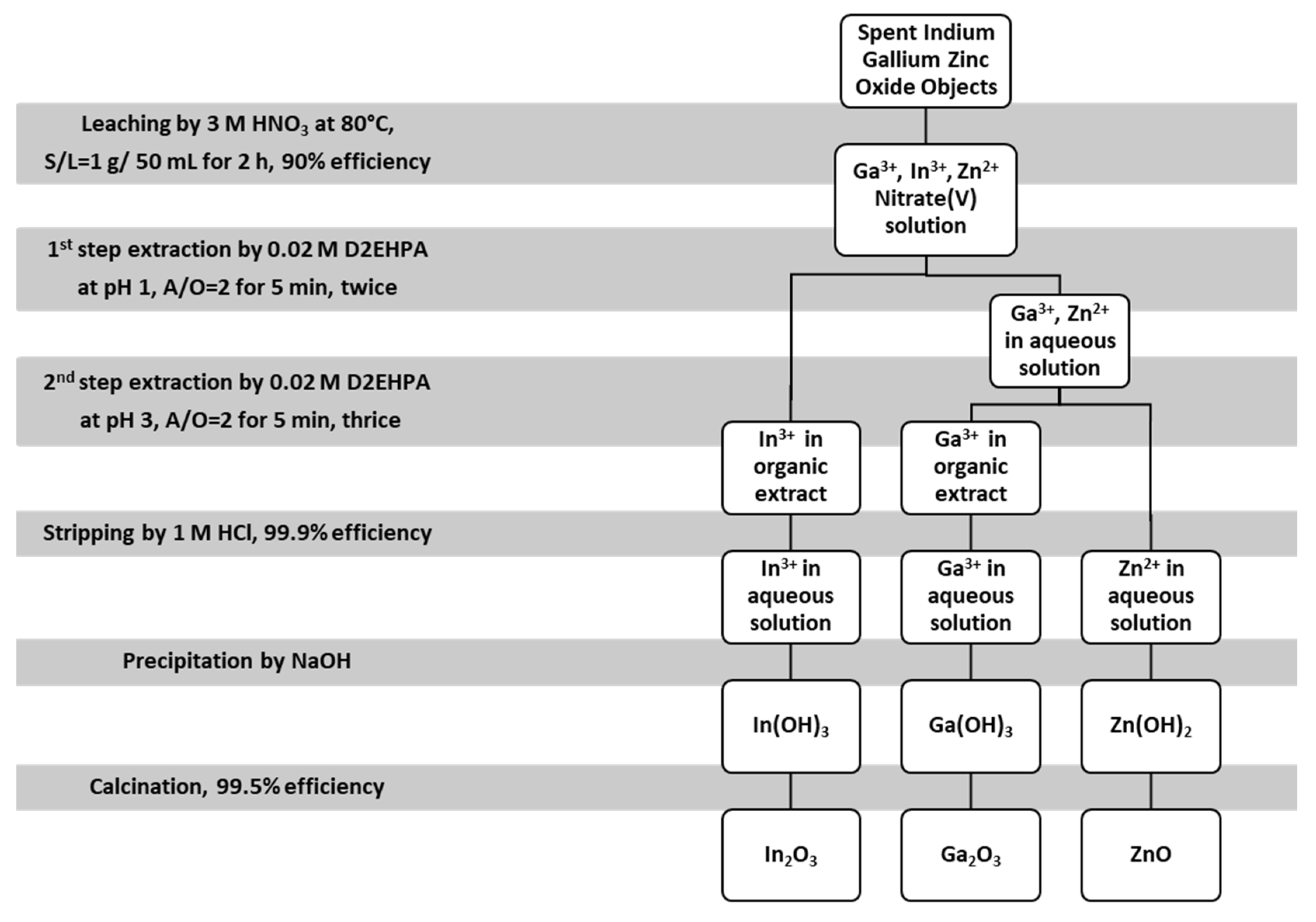
3.3.3. Separation of Ga and In

In many cases, gallium and indium occur together in the solutions. They can be isolated in two ways: by using one common extractant or two extractants selective for ions of one of these metals. In the first case, the extract obtained contains both gallium and indium, and their actual separation occurs because two different solutions are needed for their re-extraction, differing, for example, in concentration. The second method involves carrying out two extractions: during the first one, the solvent used will be selective towards one of the metals, and during the next one the solvent used will be selective towards the other. Of course, it is also necessary to consider other ions present in the solution.
Extractants used for the separation of gallium and indium can be acidic, basic, or neutral. There is a wide range of them available on the market, and the choice depends on the individual case [31]. Some examples will be presented.
The use of Cyanex 272 allows for the isolation of gallium and indium from a solution of hydrochloric acid. As described earlier, the efficiency of the process decreases when the acid concentration exceeds 0.1 M, and with concentrations of 1 M or more, it starts to increase again. A dilute acid solution is used to wash out gallium, while the quantitative washing of indium requires the use of a concentrated solution [68].
Another example may be the use of D2EHPA for the extraction of gallium and indium from solutions containing significant amounts of Zn(II). Depending on the solution pH at which the process is conducted, it is possible to isolate both at once or separately. If the pH is 2.2, the extract will contain both gallium, indium, and a small amount of zinc. They are then separated using appropriate solutions. Extraction at a pH of 1.48 ensures selectivity towards indium, while extraction of the raffinate at a pH of 1.99 allows for selective isolation of gallium. Studies have shown that the re-extraction of these metals from the extract is more effective using the H2SO4 solution compared to the HCl solution [69].
Valuable metals can be effectively extracted from nitric acid solutions after leaching of CIGS solar panels through a sequential extraction process (Figure 8). The first step involves extracting In using di-(2-ethylhexyl) phosphoric acid, while Cu and Ga remain in the aqueous phase. After extracting In, Ga is extracted using the same extracting agent but under different conditions. The residual aqueous solution contains nearly pure Cu. To form metal hydroxide precipitates, ammonium hydroxide is added to the three solutions. Under optimal conditions, a recovery efficiency of over 90% can be achieved for In, Ga, and Cu. Additionally, the formed hydroxides can be recycled and converted into metal oxides, with a purity of over 99%, through calcination [36].
Another, perhaps slightly unusual, but certainly worth mentioning, possible extraction method is an extraction using scCO2—carbon dioxide under supercritical conditions. Furthermore, the addition of a chelating agent is also necessary. This method was used to recover indium from a solution after leaching of ITO and was able to reach over 90.8% extraction efficiency (in relation to the indium content in the ground material). The optimal conditions established during the testing of this method were as follows: the chelating agent was HFOD and the extraction was carried out at 80 °C, under a pressure of 20.7 MPa, and for 30 min. The efficiency of indium recovery from the solution was 93.3% [60].
Solvent extractants yielding high extraction efficiencies and separation of metals are listed in Table 3.

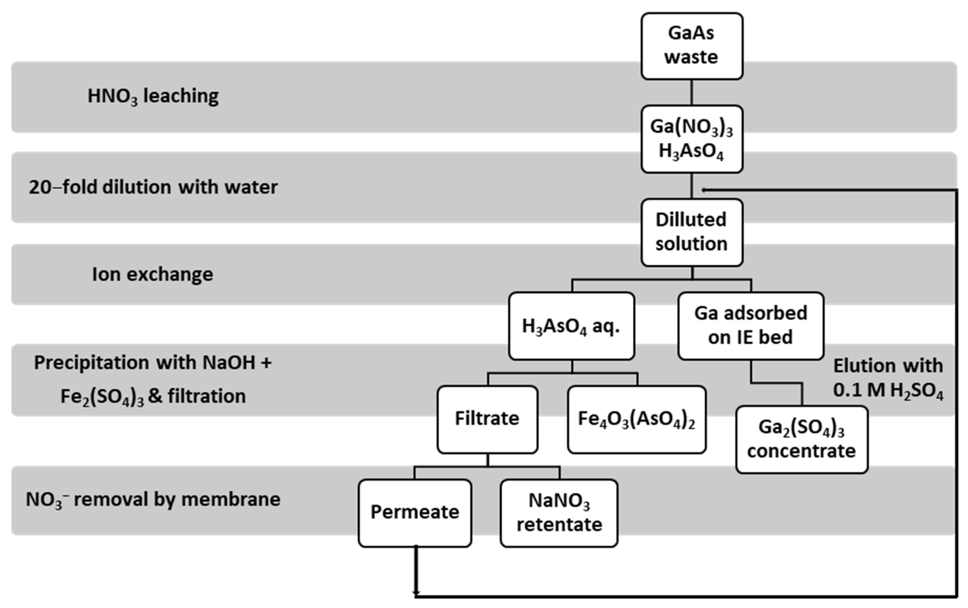
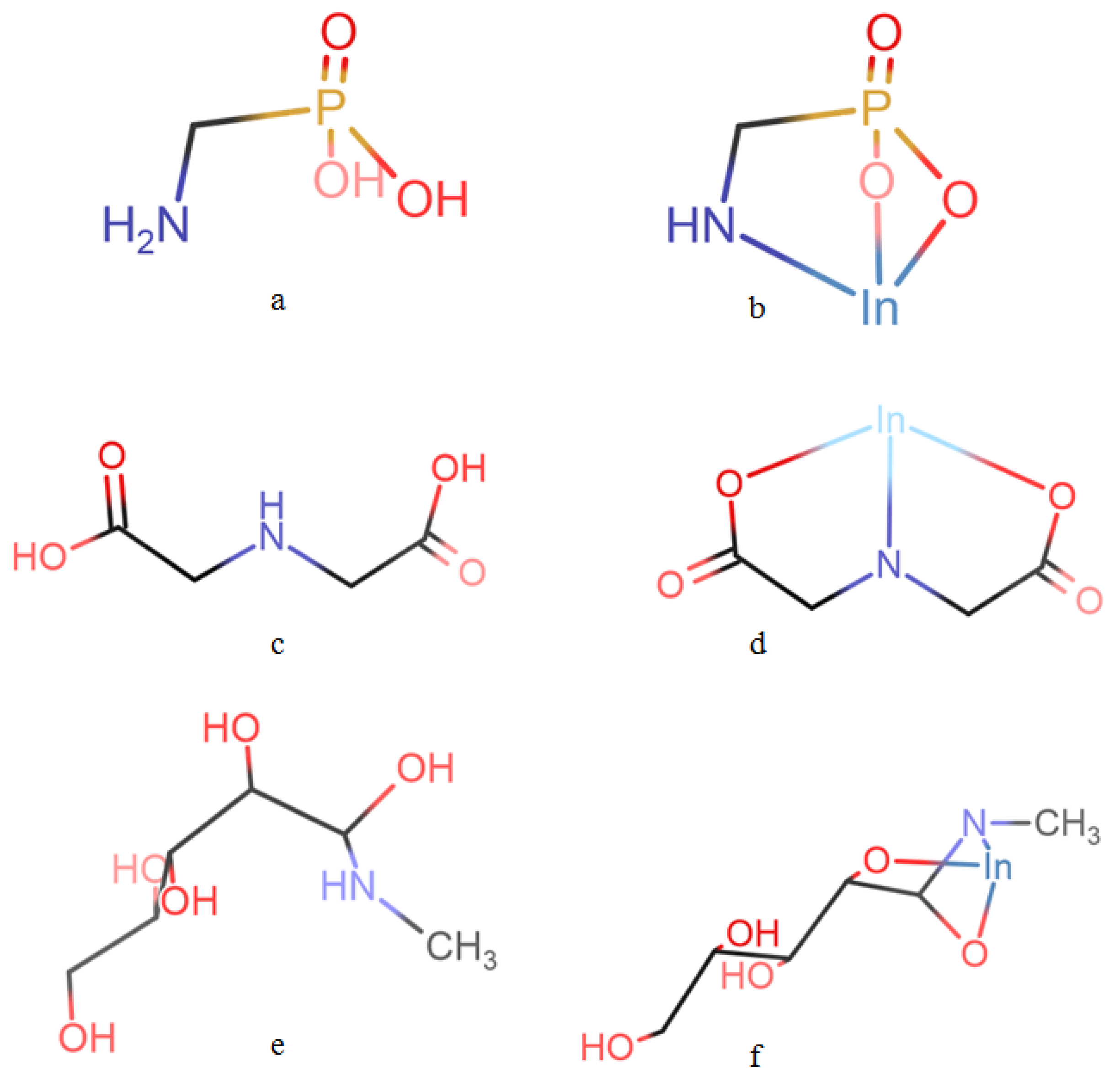
3.4. Sorption and Ion Exchange

Similar to solvent extraction, the choice of a sorbent for the recovery of gallium and indium from solutions also depends on its affinity for these metals and its selectivity to their forms present in the solution.

3.4.1. Sorption Using Silica Gels, Carbons, Minerals, and Biomaterials

Silica gels demonstrate high adsorption efficiency for gallium. Impregnating them with appropriate solvents further improves this ability. The choice of solvent also depends on the type of acid which was used to leach the metal and what other metal ions are present in the solution. The pH of the solution is also very important, because in some cases, for example when silica gel is impregnated with D2EHPA, above a certain pH value (in this case 2) partial leakage of D2EHPA from the gel may occur [71].
The use of unmodified silica gel for adsorption of gallium(III) from solutions very often requires pH correction with a buffer. Studies have shown that adsorption is quantitative at the pH of 3. Gel impregnated with n-octylaniline provides quantitative recovery of gallium from solutions containing hydrochloric acid. Its advantage is that there is no need to add a buffer, and metal elution is easy. The use of 2-hydroxy-5-(2-hydroxybenzylideneamino)benzoic acid also allows for the obtainment of high process yields [31].
In the case of indium, unmodified silica gels have much lower effectiveness of adsorption and do not show sufficient efficiency even at a very elevated pH [31]. However, silica adsorbent modified with D2EHPA, named D2EHPA/SiO2–P, exhibits excellent adsorption selectivity and kinetics for In(III), even from a solution which contains a large number of impurities, especially Fe(III). In(III) from D2EHPA/SiO2–P can be desorbed with a 3 M HCl solution, and D2EHPA/SiO2–P still has high adsorption and desorption efficiency for In(III) after five cycles of adsorption–desorption experiments. During the process of leaching of LCD waste with 0.1 M H2SO4, no toxic gases are released. Iron(III) ions can be reduced using oxalic acid which allows for the separation of Fe(III) from In(III) [72]. Gel modified with a nonionic surfactant called TritonX-100, containing D2EHPA micelles (known as DTS), also shows a high In(III) adsorption capacity. It is believed that the metal is bonded with the solvent by forming a chelate, which is then adsorbed onto the silica gel [31]. Probably, the O–H bond in D2EHPA participates in the substitution reaction and bonds with In(III), forming the In–O bond at the adsorption site. Furthermore, the bond order value of In–O was the lowest in D2EHPA; therefore, during the desorption process, the In–O bond was easy to break [72]. Impregnating the surface of silica gel with n-octylaniline or 2-hydroxy-5-(2-hydroxybenzylideneamino)benzoic acid also allows for the obtainment of high sorption efficiencies [31].
Research was also carried out on the adsorption of gallium from solutions using activated bentonite. Bentonite is a clayey montmorillonite rock that swells in water. It is also known as “bleaching earth”. In addition to montmorillonite, it also contains quartz, feldspars, and mica [73]. In the studies, bentonite was activated with sulfuric acid, and as a result of sorption, 99.1% of gallium was recovered from a gallium(III) nitrate solution. The research shows that the adsorption efficiency is positively influenced by both an increase in the pH (the research was carried out in a pH range from 1 to 3 so that the Ga(H2O)6NO32+ form dominated in the solution) and an increase in the mass of bentonite involved in the process. However, increased temperature significantly reduces the efficiency of the process and should be maintained at around 20 °C. The optimal sorption conditions were as follows: a temperature of 20 °C, a solution pH of 2.50, and a bentonite mass of 3.50 g per 1 L of solution [74].
Modified bentonite has also been used as an indium sorbent. The so-called CCB, i.e., chitosan-coated bentonite, turned out to be a promising solution, and its adsorption capacity for indium is approximately 5.79 mg/g [75].
New composite materials, created by combining carbon nanotubes (CNTs) with UiO-66 series metal–organic frameworks (MOFs), can improve the recovery efficiency for Ga in solution [76]. CNT is a unique material composed of graphite multilayers, with a hollow tubular structure, excellent mechanical and structural properties, and a high specific surface area. MOF, on the other hand, is a type of porous crystal material characterized by a high specific surface area, high porosity, adjustable pore structure, and strong stability. UiO-66, which is one of the MOFs, has an ordered micropore structure that enhances the compatibility of the polymer matrix and creates more active sites. This can improve the transmission rate, and it has a high potential for use in the adsorption and recovery of metal ions. By combining CNT with UiO-66, better composite materials can be produced, which retain the original morphology and pore structure of MOF while being well dispersed in various solvents [76,77]. Using 2-CNT/UiO-66-NH2 composite at 40 °C and a pH of 8, the maximum capacity of Ga adsorption is 925.44 mg/g, and the efficiency at which it is adsorbed can reach 99% after only 1 h [76].
Adsorption of indium via MOFs of UiO-66 is also possible (a maximum adsorption capacity of 11.75 mg/g was recorded). In a solution with a pH of 1, even common, coexisting ions, such as magnesium and aluminum, do not disturb the adsorption of In(III). Furthermore, UiO-66 can be easily regenerated to adsorb In(III) again in another cycle [77]. Indium can adsorb onto multiwalled CNTs too. An adsorption capacity of 40 mg/g can be achieved; however, the presence of other cations in the solution has a significantly negative impact on the process [78].
Indium recovery from aqueous solutions is also possible using an iron–magnesium composite (MgFe2O4). In optimum conditions, this material obtained a maximum adsorption capacity of 46.4 mg/g, and very efficient desorption with a 15% HCl solution was also possible, which allowed for 10 adsorption–desorption cycle tests [79].
Phosphoryl sawdust bead can be used as a sorbent in both batch and column systems, and the adsorption efficiency increases with its quantity. The highest adsorption capacity recorded was 0.95 mg/g; however, approximately 20% of the adsorbed indium cannot be washed out during the bed regeneration [80].
Hydroxyapatite (HAP) is a naturally occurring mineral, that can be used in the recovery of indium from solutions. HAP was coupled with two surfactants: Pluronic P123 and Pluronic F127. Maximum adsorption capacity estimated using the Langmuir model was c.a. 11 mg/g for all sorbents: HAP, HAP P123, and HAP F127 at the optimum pH of 4 and with a time elapsed ranging from 15 to 45 min. Copper, cadmium, tin, and zinc did not interfere with the removal of indium. The studied adsorbents can be applied for multicycle wastewater treatment, demonstrating high adsorption and desorption capacity during three cycles [81].
Biomaterials consisting of living organisms or their remains can also be used to adsorb indium from solutions. It turned out that the marine gram-negative bacteria Shewanella algae are capable of selectively adsorbing indium. They can function in the solutions derived directly from the leaching of indium-containing materials with an HCl solution. Using them is simple, but very time-consuming, so they are not expected to be used on a large scale [23].

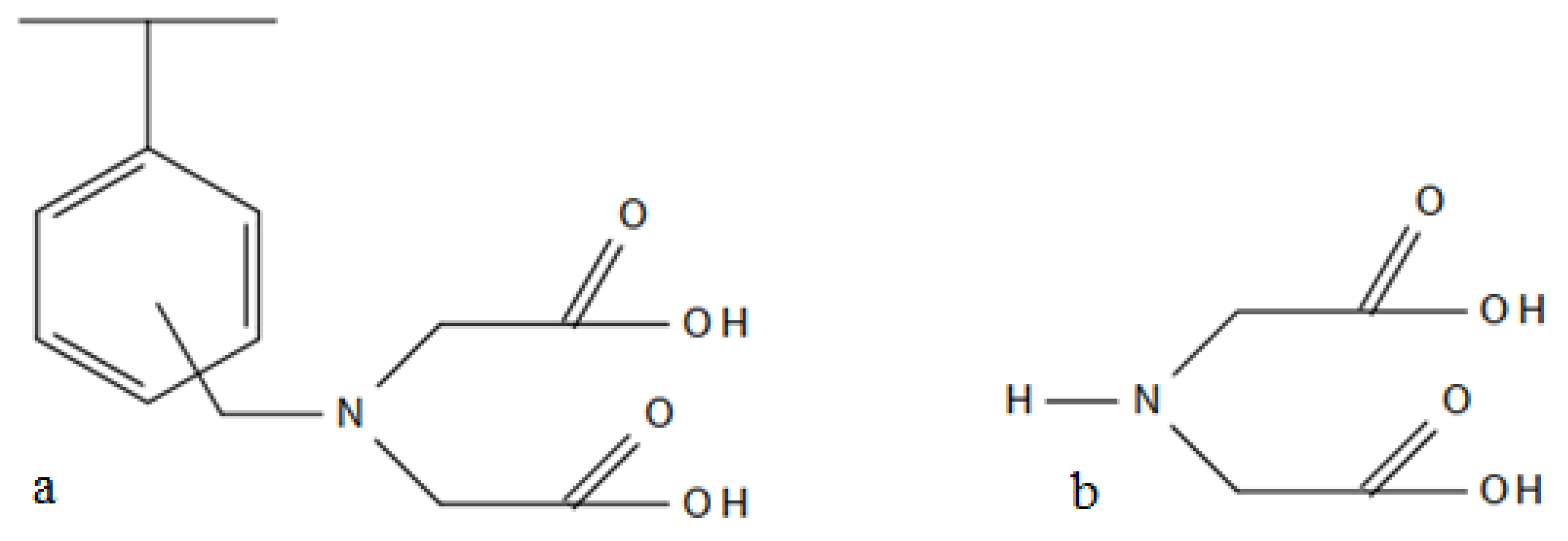
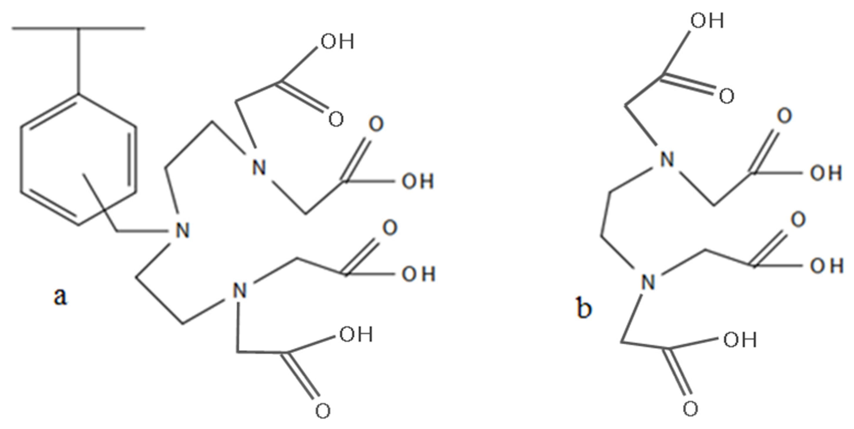
3.4.2. Sorption Using Polymer Resins

Several ion exchange resins also deserve attention. A porous resin with the trade name XAD-7 impregnated with Cyanex 923 is characterized by a high adsorption capacity towards In(III) [31]. Styrene-divinylbenzene copolymer impregnated with sec-octylphenoxyacetic acid is also a very good indium sorbent. The adsorption process can be carried out in a wide temperature range, at a pH of 3. Unfortunately, only three bed cycles are possible [82]. Strongly basic (with quaternary ammonium functional groups on polystyrene–DVB matrix) gel-type resin (Varion AD) in a chloride form was used to recover indium via ion exchange. A purified indium solution obtained from the anion-exchange procedure was neutralized to a pH 7 via a 5 M NH4OH solution to obtain In(OH)3. It was then redissolved in HCl, obtaining a solution with 72 g/dm3 In concentration, which was used to electrodeposit pure metallic indium (of 99.9997% purity) using DSA anodes and Ti cathode blanks [39].
IRA-900 is another strong base anion exchange resin. It consists of a macroporous styrene–divinylbenzene matrix that has quaternary ammonium functional groups. This resin can be used to separate and recover indium from a sulfuric acid solution by using the HSO3/HSO4 ligand. Initially, In(III) forms a complex anion with HSO3/HSO4. This complex anion can then be adsorbed by the IRA-900 anion exchange resin through ion exchange. IRA-900 demonstrated the best adsorption selectivity to indium at a concentrations of sodium sulfide and sulfuric acid of 0.5 mol/dm3. It had an adsorption capacity of 95.56 mg/g at 318 K after 30 min. In contrast, the adsorption capacities of Al, Sr, Fe, Zn, and Cu were weak. The In(III) recovery efficiency was about 99.6%, which indicates that the resin is effective for the separation and recovery of indium from ITO films [83].
Impregnating polymer resins with appropriate solvents allows for or improves the separation of gallium, indium, and zinc from the sulfate solutions. For example, it was proposed to use EHEHPA and D2EHPA solvents to impregnate HZ-803, a macroporous resin. A solution with a pH of 1 was passed through a first column, in which indium was completely recovered from it. Then, the pH of the solution was raised to 3 and it was directed to a second column, where gallium ions and some zinc ions were adsorbed. To completely separate Ga(III) from Zn(II), the solution, after the regeneration of the second column, had to be passed through a third column [31]. In another study, to recover indium from the spent LCD screens, the efficiencies of nine ion-exchange resins were studied: Lewatit TP207, Amberlite IRC 748, Purolite MTS 9300, Lewatit TP 260, Lewatit SP 112, Amberlite IR 120, Lewatit VP OC 1026, Lewatit TP 272, and Reillex HPQ. Among the tested resins, Lewatit VP OC 1026, which was impregnated with D2EHPA, was found to be the most selective towards indium in solutions with high concentrations of Al, Ca, and Fe. Optimal leaching conditions were established, which included a H2SO4 concentration of 0.2 M, a pulp density of 50% w/v, a temperature of 70 °C, and a time of 30 min. Lewatit VP OC 1026 resin was able to adsorb up to 34.6 mg of indium per 1 g of resin from the post-leaching solution with an initial indium concentration of 102 ± 7 mg/dm3 at 25 °C. Indium could be partially eluted (78%) with a 1 M HCl solution or completely eluted with a 5 M HCl solution. At the end of the regeneration/elution tests, a final solution with an indium concentration of about 242 ± 29 mg/dm3 was obtained, which contained less than 2 mg/dm3 of other impurities [84].
Polymer resins containing complexing functional groups are another promising solution thanks to their high selectivity towards Ga(III) and In(III) [73]. Of the available complexones, two, in particular, have been shown to have the ability to form exceptionally stable complexes with these metals: iminodiacetic acid (IDA) and ethylenediaminetetraacetic acid (EDTA). Although they cannot be directly attached to a polymer surface, other reagents have been used to obtain resins whose functional groups mimic IDA and EDTA structures and behaviours. A polystyrene resin with active groups that have a structure analogous to IDA is called IDA resin, while another polystyrene resin with active groups that are similar to EDTA is called CMA resin. Figure 9 and Figure 10 show the structures of the complexones and the corresponding resins [1].
Both resins allow for the quantitative adsorption of gallium and indium from the solutions. The maximum capacity of the ion exchanger for the given metal depends on the pH at which the process is carried out. The maximum capacity of the IDA resin in the case of gallium is 0.9 mmol/g of resin at a pH of 2.8, and in the case of indium, it is 1.2 mmol/g of resin at a pH of 2. The CMA resin is capable of adsorbing a maximum of 1.5 mmol of gallium/g of resin at a pH of 2 and 1.4 mmol of indium/g of resin at a pH of 1.8. Both metals can be removed from the resins by regenerating the beds with a 2 M hydrochloric acid solution. It is worth noting that the complexes formed with the functional groups of the CMA resin are much more stable than those formed with the IDA resin. Moreover, a breakthrough point of the CMA bed is reached later than that of the IDA bed [85].
Tests have shown that both resins can effectively separate gallium or indium from solutions additionally containing Al(III) ions. Moreover, the CMA resin is also able to selectively adsorb them from solutions containing Zn(II) and Ca(II) ions as well. However, it shows greater selectivity towards Fe(III) ions than towards In(III) and Ga(III), and its selectivity towards Cu(II) is very similar to its selectivity towards Ga(III). Therefore, if the presence of Fe(III) or Cu(II) is suspected in the raw solution, it is necessary to remove them beforehand. Most often, hydrogen sulfide gas is passed through the solution, which causes the precipitation of copper sulfide and the reduction of Fe(III) to Fe(II)—towards which the CMA resin is much less selective [85].
The chelating resin with the trade name Diaion CR 11 has a similar structure to the IDA resin, but in the active groups, the mobile ions are Na+, not H+. A method of arsenic and gallium recovery was developed using Diaion CR-11 from waste containing gallium arsenide, which allows for the obtainment of a concentrated gallium solution with a purity of approximately 99.3%.
Gallium and arsenic were leached with a 2 M nitric acid solution for about 30 min at 30 °C and an S/L ratio of 2 g/100 cm3. About 98% of gallium and arsenic present in the waste were transferred to the resulting solution, which was very acidic and its pH was usually lower than 0. Because at the higher pH, the breakthrough point of the bed is reached more slowly and the capacity of the ion exchange for gallium increases, the solution was diluted before passing it through the column. Dilutions ranging from 1/5 to 1/40 were tested, and the capacity of the ion exchanger increased with the dilution and amounted to 0.14 mmol/cm3 of resin and 0.38 mmol/cm3 of resin within this range, respectively. The twenty-fold dilution was chosen because, in addition to the satisfactory ion exchange capacity of 0.37 mmol/cm3 of resin, it also allowed for the obtainment of a good Ga/As partition coefficient of 115. Ga3+ ions were present in the solution, while arsenic appeared in the form of H3AsO4. It was passed through the column with a hydraulic loading of 1 BV/h, and the process ended after 35 BV had flowed. It is assumed that gallium forms a complex with the active groups of the resin via the reaction mechanism presented in Figure 11 [1]. Regeneration of the ion exchange bed was achieved with a 0.1 M solution of sulfuric acid, resulting in a Ga2(SO4)3 concentration of 4.5 g/dm3 in the final solution [29].
The effluent from the column was sent for further processing, during which, as a result of the addition of NaOH and iron(III) sulfate, a precipitate of Fe4O3(AsO4)2 was formed. The maximum amount of arsenic that could be removed in this way was 95% and required the process to be carried out at a pH of 6 and an iron/arsenic ratio of 3.6. Then, the precipitate was filtered and the solution was sent to a nitrate anion purification process, which is usually carried out using a membrane method. Then, the solution purified in this way could be returned to the beginning of the process, where it can be used to dilute the solution after leaching [29]. A schematic diagram showing the entire described technology is shown in Figure 12.
Studies have shown that gallium adsorption in batch systems yields very good results, as long as the volume ratio of the resin to the solution is 1:20. The contact time between phases usually lasts an hour. The situation is similar in the dynamic systems, where the process parameters are set so that 20 units of solution volume pass through 1 unit of resin volume per hour. Many chelating resins can be used for gallium adsorption under these conditions. They are divided into three types [86]:
  • Resins which have a –NOH group and a functional group capable of forming a chelate with it via gallium;
  • Resins which have active groups with a structure analogous to 8-hydroxyquinoline;
  • Chelating resins with a high affinity for gallium, which have groups containing several electron donor atoms (e.g., O, N, or P), for example –NHOH and –P(O)(OH)2H.
Similarly to gallium, the use of iminodiacetate resins for indium recovery also gives very good results. Research has shown that this type of resin, commercially named Amberlite IRC 748, allows indium adsorption with an efficiency of 99.5% in the dynamic system. Then, the metal ions can be washed out with a solution of sulfuric acid, with a flow rate of 5 cm3/min. It is also possible to recover indium using cellulose functionalized with iminodiacetic acid. The adsorption capacity of chelating cellulose is 1.5 mmol/g and can be achieved at a pH of 3.5 in the presence of zinc(II) ions [87].
Other ion exchangers with high selectivity towards indium turned out to be basic anion exchangers with the trade names Amberlite IRA 400 AR, Amberlite IRA 420, Dowex 1, and Amberjet 4200 CI. They enable the adsorption of indium from solutions containing platinum and tin. To isolate indium from the bed, the resins are washed with 0.1 M EDTA solution. Then, indium is precipitated from this solution by dropwise addition of a Na2S solution with a concentration of 3 M at a temperature of 80 °C. The resulting yellow–brown In2S3 precipitate contains indium with a purity of 99% (m/m) [37]. The chelating aminodiacetic resin with the trade name Ionac® SR-5 and the resin containing diphosphonic acid groups with the trade name Ionac R12 show a similarly high degree of adsorption of indium. Ionac SR12 additionally shows a greater selectivity towards indium when iron ions are present in the solution: the loading percentage of resin for indium was 40%, while for iron it was 5%. Ionac SR5 can be used for the adsorption of indium from solutions containing sulfuric acid [37].
A very effective solution is the use of macroporous polystyrene–divinylbenzene resins equipped with the following functional groups: (aminomethyl)phosphonic and iminodiacetate. The trade names of these resins are Lewatit TP 260 and Lewatit TP 208. The proposed process of indium recovery from LCD panels using these resins was carried out in the batch system. A resin with N-methylglucamine groups with the trade name Amberlite IRA 743 was also tested, but it gave much worse results. Indium was leached from the separated LCD panels and ground ITO glass using a mixture of hydrochloric and nitric acids, in which their concentrations were 3 M and 0.5 M, respectively. The leaching was carried out for 5 min at a temperature of 70 °C and an L/S ratio equal to 5 cm3/g. Additionally, the system was treated with ultrasound (300 W) and stirred at a speed of 500 rpm. The optimal adsorption conditions proposed by the researchers were as follows: a temperature of 25 °C, a pH of 2, a contact time of 30 min, and an L/S ratio equal to 50 cm3/g of resin. After the process, the resin was filtered and regenerated with 2 M HCl for approximately 5 min. During regeneration, additional mixing was performed and the S/L ratio was 10 cm3/g. The concentrations of In in the solutions obtained after regeneration reached up to 120 mg/dm3. The adsorption and desorption efficiencies were, respectively, 84.7% and 83.3% for Lewatit TP 260, 94.2% and 94.0% for Lewatit TP 208, and 54.7% and 53.3% for Amberlite IRA 743 [43].
The use of Lewatit TP 208 allowed for the highest recovery of indium, although the amine group is present in all three chelating resins. It is assumed that this is related to the symmetry of the iminodiacetate group in Lewatit TP 208 and may provide it with a greater affinity for In(III). Moreover, this group is also characterized by a lower steric hindrance than the other two, which may also contribute to the fact that it is easier for it to interact with indium ions [43]. The structures of all three active groups before and after the addition of indium are shown in Figure 13 [1].

3.4.3. Separation of Ga and In in an Acid Solution

Indium and gallium can be separated from the solution of hydrochloric acid using the relationship between the occurrence of different forms of these metals and the acid concentration—in short, via the cation and anion exchange. In the solutions with a concentration of 0.1 M and 1.5 M HCl, the cationic forms In(H2O)63+ and Ga(H2O)3+ dominate, respectively. In the case of indium, the anionic forms begin to dominate at a concentration of 1 M, and for gallium at a concentration of at least 2.5 M. Therefore, with appropriate changes in the acid concentration, it is possible to separate gallium from indium ions using first a strong acid cation exchanger (e.g., an ion exchanger with the trade name Dowex 50W X8), and then a base anion ion exchanger (e.g., an ion exchanger with the trade name Dowex 1 X8) [88].
Indium, gallium, and zinc were separated from the solution obtained in the process of gallium-based liquid metal (G-LM) waste leaching with 3 M HNO3 solution for 2 h at 40 °C. Under these optimal conditions, more than 99.99% of Ga, In, and Zn were leached and then adsorbed on a CL-P204 solvent-impregnated resin. The metals were then eluted using HCl solutions with varying pH levels. The results showed a recovery efficiency and purity of 96.01% and 99.49% for gallium, and 99.83% and 98.23% for indium, respectively. The leaching efficiency for tin was only 4.43%, and it was mainly found in the slag phase as β-H2SnO3. The P204 solvent-impregnated resin used in the experiments can be recycled [52].
On the other hand, when the solution obtained in the process of waste leaching contains sulfate ions, it was proposed to use HZ-803 resin impregnated with EHEHPA and D2EHPA solvents to separate indium, gallium, and zinc. A solution with a pH of 1 was passed through a first column, where indium was completely separated from it. Then the pH of the solution was raised to 3 and it was directed to a second column, where gallium ions and some zinc ions were adsorbed. To completely separate Ga(III) from Zn(II), the solution after regeneration of the second column had to be passed through a third column [31].

3.5. Precipitation

Precipitation is a classic method, used primarily in the separation of indium and tin from solutions after leaching of ITO glass. Increasing the pH of the solution causes indium to precipitate in the form of indium(III) oxide.
One method involves the addition of an oxidant to the solution (for example, hydrogen peroxide), in the presence of which tin precipitates completely from the solution at a pH of 3.5, while indium remains in the solution. When the pH increases above 4–5, indium(III) oxide then precipitates. Chemical precipitation alone makes it possible to obtain indium with a purity of 99.99%, and if the method is combined with solvent extraction, it is possible to obtain a recovery efficiency of 99.999%.
Precipitation of indium from solutions containing zinc and iron ions can be carried out at 90°C using an ammonia solution, at a pH of 6. Metals accompanying indium do not precipitate in such conditions [37].
The precipitation method can be also used to separate and recover indium from Pb–Ag tailings. Following the leaching of the roasted material in water, Pb, Ag, and most of the Fe remain in the solid residue. The leaching solution can be treated further with precipitation using NaOH, where In and the remaining Fe are precipitated, in comparison to Cu and Zn which remain in the solution. In(OH)3 and Fe(OH)3 precipitates can be dissolved further in a diluted H2SO4 solution, and then a cementation of In with Al can be performed. Next, HCl can be used to separate Al from In, after which raw In is obtained [89].

Separation of Ga and In with the Precipitation Method

No research papers on the separation of gallium and indium using the precipitation method were found. To explore this possibility, the use of a Pourbaix diagram can be very helpful. This diagram visually displays the ionization equilibrium of various ions in the system and indicates the conditions for their stable existence. Figure 14 shows the Pourbaix diagrams for the Ga–H2O system and In–H2O system, both with a concentration of 1 mol/dm3 at 25 °C and 60 °C [30]. Figure 14a shows that for the Ga–H2O system, as the pH of the system increases, the form of gallium changes from gallium ions to gallium hydroxide precipitate. The dissolution of the Ga(OH)3 precipitate and the formation of the highly soluble Ga(OH)4 complex ion can be observed at pH levels around 8 or higher. On the other hand, Figure 14b shows that for the In–H2O system, as the pH of the system increases, the form of indium changes from indium ions to indium hydroxide precipitate. Even at a strongly alkaline pH of 14, no dissolution of the In(OH)3 precipitate is observed. Other references indicate that above a pH of 12, In2O3 is transformed into the InO2 ion [90,91].
The Pourbaix diagrams indicate that gallium and indium exist as Ga(OH)4 and In(OH)3, respectively, in a wide alkaline environment, and their dominant regions expand with the increase in temperature of the system. This implies that by raising the pH and temperature of the system, the precipitation method can potentially be used to separate gallium and indium.

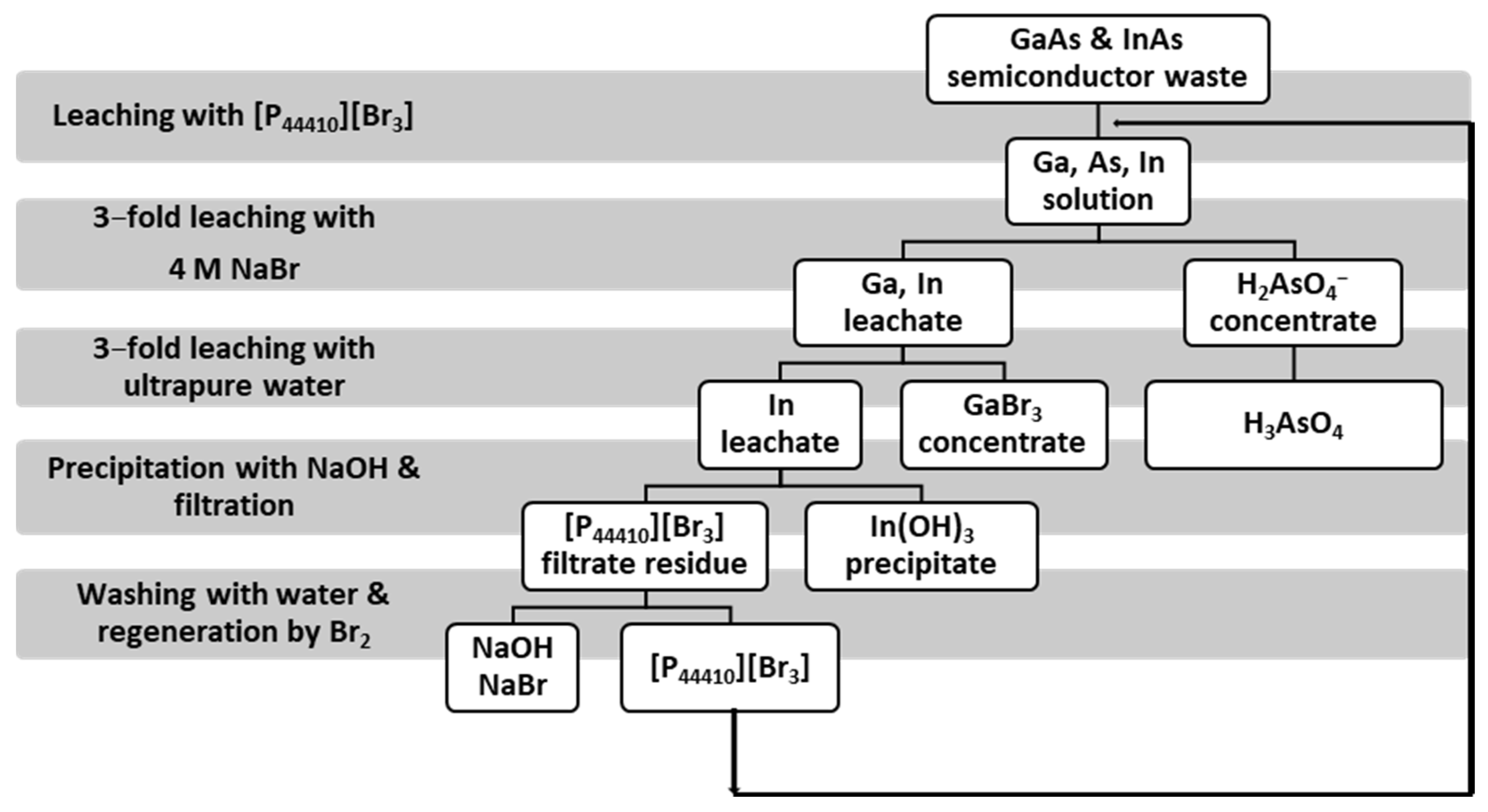
3.6. Ionic Liquid Use

With the rising trend towards green technologies, recent years have seen an increase in the use of ionic liquids (ILs) in the extraction of important metals from aqueous solutions. Ionic liquids (ILs) based on phosphonium cations can be promising extractants for metals, including gallium and indium. The use of tributyldecylphosphonium tribromide ionic liquids [P44410][Br3] for the recovery of gallium, indium, and arsenic from waste containing GaAs and InAs turns out to be very effective. The process consists of two stages: leaching of metals from semiconductor materials using ILs, and their selective recovery from the ILs solutions using appropriate regenerating substances. In addition to the high efficiency of 95% or more for all three metals, the great advantage of this method is the fact that arsenic is obtained in the form of H2AsO4. It is much less toxic than the AsH3 form usually obtained in other recovery methods. In the leaching process, the molar ratio of GaAs, InAs, and ionic liquid [P44410][Br3] is 1:1:20, respectively. As a result of the ionic liquid regeneration process, over 99% of metals can be recovered. To remove arsenic from the ionic liquid, a 4 M NaBr solution can be used, which allows for the obtainment of H2AsO4 in a three-stage process. Gallium can be removed by washing the ionic liquid solution three times with distilled water and then indium can be precipitated in the form of indium(III) hydroxide by contacting the ionic liquid with a sodium hydroxide solution. The ionic liquid can be regenerated with the addition of molecular bromine and then reused. Figure 15 shows a schematic diagram of the process along with the exact concentrations of the separated metals in the solutions obtained after the specific steps [55].
In another study, acid–base bifunctional ionic liquids (Bif-ILs) in both solvent extraction and supported liquid membrane (SLM) processes were examined to separate and recover gallium from aqueous solutions. The SLM containing Bif-ILs demonstrated a highly selective transfer of 96.2% of Ga(III) from the feed into the stripping solution, containing Al(III), Mg(II), Cu(II), and Fe(II). After five cycles, the process efficiency showed only a slight decrease to 88.1% [92].
Indium recovery from discarded LCD screens is possible using Cyphos IL 101 diluted in kerosene as the organic phase. The maximum efficiency of indium recovery was 99.7% at optimum conditions which were as follows: 4 M aqueous phase acidity, 197.79 ppm of indium, 0.009 M ionic liquid, and 1.58 mol/dm3 of aqueous to organic phase ratio [93].
In a solution in which the HCl concentration ranges from 1 M to 3 M and the accompanying ions are Al(III) and Ni(II), complete selectivity towards gallium is ensured by the use of trihexyl(tetradecyl)phosphonic chloride (trade name Cyphos IL 101). However, if Cu(II), Zn(II), or Fe(III) ions are also present in the same solution, it would not be possible to separate gallium from them with good efficiency. As with previous cases, this extractant can be regenerated using an HCl solution [65]. To solve the difficulty in the traditional solvent extraction process of stripping Ga(III) from the loaded organic phase, a low acidity aqueous solution with a pH of 2 can be introduced as the stripping agent of the Aliquat 336-based supported liquid membrane (SLM). This method allows for the selective separation of low-content Ga(III) ions from mixed solutions of concentrated hydrochloric acid that contain other metal ions like Fe(II), Al(III), Mg(II), and Cu(II) under optimal process conditions [94].
Some ILs were synthesized in a reaction of Aliquat 336 with organophosphorus acids (Cyanex 272, D2EHPA, and PC88A), resulting in the formation of ALi-CY, ALi-PC, and ALi-D2. These ILs were then used to selectively extract Ga(III) and In(III) from a solution with an initial pH ranging from 0.1 to 2.0. The highest separation coefficient between In(III) and Ga(III) was 87, and it was achieved by using ALi-PC with an initial pH of 1.0. Stripping of the loaded ALi-PC with hydrochloric and sulfuric acid selectively removed In(III) over Ga(III). However, only half of the Ga(III) loaded in ALi-PC was scrubbed by using a pure In(III) solution. Batch simulation experiments for three counter-current extraction stages showed that extracting In(III) using ALi-PC made it possible to completely separate both metal ions, with Ga(III) being left in the raffinate [95].

3.7. Obtaining Pure Oxides and Metals

To separate pure gallium and indium or their oxides from the solutions, additional technological procedures such as cementation or electrolysis are necessary. If the final product is not pure enough, it is also subjected to a refining process.

3.7.1. Cementation

Gallium can be isolated from neutral solutions using zinc dust. As a result of this reaction, gallium is “replaced” in the solution with zinc, which dissolves during the process while gallium is precipitated [96].
Zinc or aluminum are most often used for indium cementation [96], with the best results achieved in chloride solutions. Reducing agents are used both in the form of plates and powders. The zinc plate proves to be low efficiency; however, Zn powder performs well. In the case of aluminum, both the plates and the powder work well, and virtually complete recoveries of indium could be achieved within 10–60 min—depending on the pH and temperature of the solutions. The produced sponge can be removed easily from the Al plates and efficiently melted under a protective atmosphere, vacuum, or salt flux. The purity of the produced sponges can generally be above 99.9%, and the reduction on the Al plates produces the purest indium [97]. The cemented sponge can be vacuum melted to produce an indium anode block of >99.9% purity used for electrorefining. Galvanostatic and potentiodynamic results show that the optimal electrolyte conditions are 50 g/dm3 of In, 1 M of free Cl ions, and a pH of 1. The cathodic deposition of Zn, Mn, and Fe is negligible; however, the prior removal of Cu and Sn from the electrolyte is required for producing high-purity indium [41].
The method of cementation that uses the aluminum plate is highly effective in recovering indium from the pregnant leach solution after processing of the waste indium phosphide (InP). When the reaction temperature is maintained at 85 °C, the indium sponge precipitates and can be separated easily from the surface of the aluminum plate, thus simplifying the cementation process. The cementation process can achieve over 90% recovery efficiency for indium in its metallic sponge form [42].

3.7.2. Hydrogen Reduction

Adding an excess of NaOH to a solution of gallium or indium allows the precipitation of their hydroxides, from which their oxides are then obtained via simple roasting or calcination [31,96]. In2O3 and Ga2O3 can then be reduced with hydrogen (in the case of gallium oxide, the process is carried out at 900 °C), allowing for the obtainment of raw metals [96].

3.7.3. Electrolysis

Electrolysis of gallium solutions usually involves two steps. The first stage is called initial concentration. It is usually carried out in electrolysers with a rotating drum that is partially immersed in mercury [77]. The cathode is the rotating drum made of steel and covered with sodium amalgam. Mercury also contains some sodium metal [96]. The cathode surface is constantly renewed as a result of the drum movement, and its overvoltage prevents the creation of hydrogen. Gallium dissolves in mercury with some iron and sodium, together with some impurities such as lead, copper, and zinc, if present in the solution. The saturated amalgam of gallium and sodium is directed to a decomposition vessel, where mercury is purified from gallium and the accompanying metals using hot water or NaOH solution. Mercury is returned to the electrolyser and the obtained concentrate is sent to the second stage [96,98]. Again, the electrolysis process is carried out. It is usually carried out at approximately 70 °C on platinum or stainless-steel electrodes. This time, hydrogen is released in the process, as a result of which the current efficiency of the process usually does not exceed 10%. An amalgam of gallium and sodium is obtained on the cathode, and after its decomposition, gallium with a purity of up to 99.9% can be obtained [96].
Indium is obtained via electrolysis of acidic solutions (when the pH is approximately 2–2.5) of indium chloride or sulfate. Electrolysis of the InCl3 solution at a pH of 2.2 and a sodium chloride concentration of 100 g/dm3 allows for the obtainment of metal with a purity of up to 99.999%. In the process, the anode is raw indium and the cathode is refined indium. Electrolysis of indium in a formic acid solution allows indium to be obtained in the form of a sponge. However, during the process indium may be contaminated with metals such as cadmium, copper, zinc, tin, and thallium [98].
Research is underway to obtain indium on a molybdenum electrode in a molten NaCl–KCl eutectic system at 750 °C. The method is currently at the stage of collecting the theoretical basis for the development of an efficient and cost-effective process for indium secondary resources recycling based on molten salt electrochemistry [99].
The method of recovery and reuse of spent ITO waste through electrochemical techniques has also been described in the publication [100]. An indium–tin alloy can be prepared via electrolytic reduction of the s-ITO target in a molten CaCl2 at 850 °C. Then, hydroxides can be synthesized via electrolysis of an In–Sn alloy in an aqueous ammonium chloride solution. Finally, oxide nanocomposites, which are used to prepare ITO, can be produced through calcination. Importantly, the process can be extended to a large-scale production.

3.7.4. Other Methods

The metals obtained with the methods described above are usually too contaminated to be used directly for certain purposes, especially for the production of semiconductors. Therefore, it is necessary to carry out additional operations to further purify them.
Gallium can be purified in six independent ways [96]:
  • Filtration. A dense filter is used, onto which raw gallium is poured at an elevated temperature. The method takes advantage of the easy fusibility of gallium and the poor solubility of many impurities in the molten gallium;
  • Chlorination. Raw gallium is subjected to a reaction with chlorine, and the resulting gallium(III) chloride is distilled from the chloride solutions containing impurities (except aluminum chloride);
  • Amalgamation. The solubility of gallium in mercury is high and increases with increasing temperature; therefore, saturating mercury with raw gallium at 400 °C, filtering out impurities, and then slowly cooling the amalgam allows for the isolation of purified gallium;
  • Zone melting method, i.e., local melting of the charge. The molten zone moves along its axis. It is mainly used for further purification of previously purified gallium or its chlorides;
  • Vacuum heating. It allows the removal of mercury from gallium by heating it under reduced pressure and at a high temperature;
  • Czochralski method. Slow extraction of a single crystal of gallium at a temperature close to solidification.
Indium can be purified with the following methods [96]:
  • Melting under a layer of NaOH + NaCN. It allows for the removal of residues of copper, zinc, cadmium, and lead (which is usually removed before electrolysis via coprecipitation of lead(II) sulfate with barium sulfate);
  • Distillation of impurities with a boiling point lower than indium (2080 °C);
  • Amalgamation. It is repeated several times and combined with the distillation of mercury under reduced pressure;
  • Zone melting method. It is described above;
  • Extraction of a single crystal from a molten indium in an inert atmosphere.
Refined gallium may contain 10−4% to 10−8% of impurities, while refined indium may contain 10−6% to 10−7% of the impurities in the final product [96].

3.8. Discussion

The mentioned specificity of e-waste is closely related to the multitude and diversity of uses of gallium and indium, and this complicates the selection of the method. Each has several advantages, but also some disadvantages (Table 4), arising from the fact that not every method is equally suitable for each form of gallium or indium, as well as from the difficulties related to the gradual loss of the reagent, its toxicity, limited access, or price.
The pretreatment stage itself must be adapted to the type of waste that will be processed. A decision must be made whether dismantling will be carried out manually or with a machine and to what extent. It is also necessary to take into account preliminary chemical treatment and calculate whether the reduction in metal losses will compensate for the costs associated with its implementation.
The selection of the grinding technique is also important, in terms of the obtained grain size, grinding time, and the accompanying material losses that occur as a result of the formation of the dusty fraction. The HEBM method, which uses the high-energy ball mill and allows for the obtainment of grains with a diameter of up to 1 μm in just a minute, seems to be a very good solution. However, it requires thorough cleaning of the material. Hammer and ball mills, which can obtain grains with a wide range of diameters, but in a much longer time (e.g., in the case of the ball mill this time is 6 h), do not have such limitations.
Moreover, the obtained grain size should be adapted to further processes, because, although a high degree of material fragmentation greatly improves the washing efficiency, it also reduces the efficiency of magnetic, electrostatic, and eddy current separations. The selection of the physical separation method depends on the other components accompanying gallium and indium in the ground material. Magnetic separation is used to separate ferrous metals, light components are separated with air classification, and the eddy current method is used to separate nonferrous metals with a high conductivity to density ratio. The remaining nonferrous metals are removed from the mixture via the electrostatic method or by using permanent magnets. Gravity separation allows for the separation of components that differ significantly in density, and flotation allows for the separation of components that differ in wettability. Knowledge of the physical properties of the material components is therefore necessary when selecting a processing method.
Nitric acid is the best choice for leaching gallium from materials containing GaAs, because, even though it is the most expensive of the mineral acids considered, it gives the best results. Using one of the three combinations of conditions presented in Table 1 enables the achievement of a leaching efficiency of up to 99%. Leaching gallium from GaN-containing materials requires more aggressive conditions: a pressure of 15 atm and a temperature of 200 °C. The alternative is to roast the material with alkaline salts. In both cases, hydrochloric acid is used and the choice between them requires calculating whether the process using a furnace and a ball mill operating for many hours or the process requiring the high-pressure equipment will be more expensive.
Hydrochloric acid, sulfuric acid, and nitric acid, as well as their mixtures or other mineral acids, can be used to leach indium from ITO. Due to having the lowest cost and lower risk to equipment, the suggested acid is sulfuric acid. Hydrochloric acid is also used because it does not generate problematic waste and is less prone to leaching toxic components from the material. Due to the high price, it is recommended to reduce the consumption of nitric acid.
Choosing a method for separating gallium and indium from the post-leaching solution requires considering what other components are present in it. Of course, issues such as price and availability of reagents are also important.
Extraction is one of the most popular methods, and there are solvents available on the market with a high affinity for gallium and indium and a low affinity for the accompanying metals such as copper, zinc, or iron. When choosing the specific extractant, the acid used in the earlier stage and its concentration should be taken into account, because they may not have the same affinity for each of the forms in which gallium or indium may occur. The serious disadvantage of this method is the gradual loss of the solvent, part of which leaves the system together with the extract and raffinate. This not only generates losses related to the need to refill the reagent but very often poses a threat to the environment. Moreover, extraction is time-consuming due to the need to keep the appropriate contact time between the extractant and the raw solution and then to separate them in a centrifuge or settler. There is also a level of minimum concentration of metal that must be present in the solution (usually several hundred ppm) for it to be carried out successfully.
Sorption methods solve the problem of solvent loss, as long as they are not impregnated with it. Many substances can be used as sorbents, liquids, gels, and solids, both synthetic and natural. Commercial sorbents (silica gels, chelating resins, and others) can be additionally modified to increase their affinity towards gallium and indium. Particularly promising sorption processes are those using living organisms or their fragments. Sorption methods are much less time-consuming than extraction. There is also no minimum concentration below which the sorption process is ineffective. As in the extraction method, the selection of the sorbent depends on the accompanying metals and the acid used in the leaching. It is also worth considering the type of regenerating agent to minimize the cost of the process.
The precipitation method is recommended only for indium recovery. The advantage of precipitation is undoubtedly the simplicity and the degree of purity of indium obtained in this way, which can reach 99.99%. This method is mainly intended for the recovery of indium from ITO and combining it with extraction, which allows for a further increase in the purity of indium to 99.999%, seems to be a very optimal solution.
The use of tribromide ionic liquids for the recovery of gallium, indium, and arsenic from waste containing GaAs and InAs allows for the quantitative isolation of all three elements. In addition to the high efficiencies of the element recovery (which are 95% or more for all), the additional advantage of this method is the fact that arsenic is obtained in the form of H2AsO4. This form is much less toxic than arsane, which is usually obtained through other recovery methods. However, so far it has not been possible to isolate gallium from the components containing GaN.
The choice of method for separating the solid component (metal or metal oxide) depends largely on the cost of electricity in a given geographical location. If it is very high, the alternative to electrolysis may be to precipitate the hydroxides, roast them to form oxides, and then use the high-temperature reduction with hydrogen. The selection of the refining and purification method of the obtained metals depends strictly on the type of impurities we expect in the system, as well as the degree of purity we ultimately want to achieve.
Because each of the presented methods of recovery and separation of gallium and indium from waste has advantages and disadvantages, the author of this study recommends using the advantages of the sorption and extraction methods and eliminating the disadvantages of these methods by using solvent-impregnated resins or gels. This solution will offer simple process conditions and good selectivity of metals, as is the case with sorption techniques, and high extraction and separation efficiency for metals, as is the case in solvent extraction. Furthermore, the loss of extractant (the main inconvenience in the extraction technique), causing environmental hazards and economic limitations, will be eliminated. The suggestion is to intensify the research activities on the recovery of In(III) and Ga(III) with solvent-impregnated resins and the selective elution of gallium and indium. After that, it will be possible to commercialize this method on an industrial scale.

4. Summary

Gallium and indium are metals of great importance for many different areas of life, from medicine and telecommunications to the entertainment industry. They are used in the form of pure metals, alloys, admixtures, oxides, compounds with other elements, such as nitrogen or arsenic, and organometallic compounds. This article addressed the issue of recovery of these metals from waste, which is an extremely important issue for several reasons.
The first is the large dispersion of gallium and indium in nature, as well as the rarity of natural minerals, which is related to the great difficulties in their isolation and separation from primary sources. Gallium and indium are obtained as the byproducts during the processing of other metal ores. In the case of gallium, the most important sources are bauxite and zinc sulfides, while for indium, zinc sulfides and (to a much lesser extent) sulfides of copper, iron, tin, and lead are the most important sources.
The second reason for the importance of this topic is the fact that gallium and indium are already on the European Union’s list of critical and strategic raw materials. This is caused by the global problem of depletion of natural resources and the threat that in several dozen years many of them will run out, including gallium and indium. It is also connected to the growing demand for these metals, mainly for the production of semiconductors and LCD panels.
The third important aspect is the problem of increasing pollution of the Earth, which is caused by toxic e-waste, the consumption of which has increased significantly in recent years. Therefore, developing and implementing methods that enable the recovery of valuable elements from waste, while limiting emissions of harmful substances into the environment, should be a priority. This will both reduce the negative impact of human activity on the environment and will bring profits because electrical and electronic waste contains many valuable elements. In addition to gallium and indium, in e-waste there are also, for example, gold, copper, and silver.
This literature review showed that it is impossible to propose a universal method of dealing with all electronic waste due to their different specificities. It can be noted, however, that the waste disposal methods described in this work are mostly hydrometallurgical processing methods and focus on the recovery of gallium and indium in relatively mild conditions. It is possible to combine different methods to recover gallium and indium from electronic waste of a given type to achieve high efficiency and repeatability of the process.
GaAs and GaN wastes are the main sources of gallium recycling, while the proportion of gallium recycling of IGZO (GZO) display and CIGS scrap is relatively low. Recovery of gallium from GaN waste is usually done through fire or wet methods, whereas the wet method is used for GaAs waste. The gallium and indium obtained from IGZO (GZO) display are mostly through acid leaching.
According to the sources, indium is not being recovered from WEEE in the European Union (EU), even though this type of waste is generally well-collected and has high concentrations of indium. To recover indium from discarded LCDs, the process could generally involve (1) collecting LCDs, (2) dismantling them either manually or mechanically, (3) treating the displays with methods such as crushing or pyrolysis, and (4) properly recovering the indium. There are several techniques for separating and purifying indium, including solvent extraction, ion exchange resins, biological metallurgy, cross-current leaching with zinc cementation, vacuum chlorinated separation, and vacuum carbon reduction. Combining these techniques could potentially increase process yields and reduce operating costs. Despite the promise of many of these processes, a complete recycling system for end-of-life (EoL) indium has not yet been established in the EU.
The suggestions for research mentioned earlier can help make the recovery of gallium and indium a profitable and common technology. However, the efforts of scientists may not yield the desired results if the bottleneck in the recycling process is not eliminated. The necessary actions that need to be taken are at the governmental level and relate to financial, procedural, and legal aspects. Governments should invest in e-waste segregation to ensure that used electronic devices are appropriately distributed to the sector responsible for their disposal.

Funding

This research received no external funding.

Data Availability Statement

No new data was created.

Acknowledgments

J.K. is very grateful to Karolina Goc for editing and proofreading the manuscript.

Conflicts of Interest

The author declares no conflict of interest.

Abbreviations

ITOIndium–tin oxide
CIGS[Cu(InxGa1−x)Se2] copper indium gallium (di)selenide (CIGS) thin-film solar cell
HEBMHigh-energy ball milling
LEDLight-emitting diode
TFTThin-film transistor
PCBsPrinted circuit boards
WPCBsWaste PCBs
RAMRandom access memory, a form of electronic computer memory
MMolar concentration [mol/dm3]
TBPTributyl phosphate
TOPOTri-n-octylphosphine oxide
LCDLiquid-crystal display
InPWaste indium phosphide
S/LSolid-to-liquid ratio
EHEHPA2-ethylhexylphosphonic acid 2-ethylhexyl alcohol ester
D2EHPAdi-(2-ethylhexyl) acid phosphoric acid
DTMPPAdi-(2,4,4′-trimethylpentyl)phosphinic acid
rpmRevolutions per minute
IDAIminodiacetic acid
EDTAEthylenediaminetetraacetic acid
GZOGallium zinc oxide
IGZOIndium gallium zinc oxide
MOCVDMetal organic chemical vapor deposition
IEIon exchange
EoLEnd-of-life

References

  1. Kalaga, K. Recovery of Gallium and Indium from Waste. Bachelor’s Thesis, Silesian University of Technology, Gliwice, Poland, January 2021. (In Polish). [Google Scholar]
  2. Menad, N.; van Houwelingen, J.A. Identification and recovery of rare metals in electric and electronic scrap. In Proceedings of the Thirteenth International Waste Management and Landfill Symposium, Sardinia, Italy, 3–7 October 2011; p. hal-00594122. [Google Scholar]
  3. Forti, V.; Balde, C.P.; Kuehr, R.; Bel, G. The Global E-Waste Monitor 2020: Quantities, Flows and the Circular Economy Potential; United Nations University: Bonn, Germany; International Telecommunication Union: Geneva, Switzerland; International Solid Waste Association: Vienna, Austria, 2020; Available online: https://ewastemonitor.info/wp-content/uploads/2020/11/GEM_2020_def_july1_low.pdf (accessed on 6 December 2023).
  4. Bhuiyan, A.G.; Hashimoto, A.; Yamamoto, A. Indium nitride (InN): A review on growth, characterization, and properties. J. Appl. Phys. 2003, 94, 2779–2808. [Google Scholar] [CrossRef]
  5. Khashan, K.S.; Taha, J.M.; Abbas, S.F. Fabrication and properties of InN NPs/Si as a photodetector. Energy Procedia 2017, 119, 656–661. [Google Scholar] [CrossRef]
  6. Elrouby, M.; El-Shafy Shilkamy, H.A.; Elsayed, A. Development of the electrochemical performance of zinc via alloying with indium as anode for alkaline batteries application. J. Alloys Compd. 2021, 854, 157285. [Google Scholar] [CrossRef]
  7. Moskalyk, R.R. Gallium: The backbone of the electronics industry. Miner. Eng. 2003, 16, 921–929. [Google Scholar] [CrossRef]
  8. European Commission, Directorate-General for Internal Market, Industry, Entrepreneurship and SMEs; Grohol, M.; Veeh, C. Study on the Critical Raw Materials for the EU 2023—Final Report; Publications Office of the European Union: Luxembourg, 2023. [Google Scholar] [CrossRef]
  9. Ervina Efzan, M.N.; Nur Faziera, M.N. Review on the effect of Gallium in solder alloy. IOP Conf. Ser. Mater. Sci. Eng. 2020, 957, 012054. [Google Scholar] [CrossRef]
  10. Luktuke, A.; Singaravelu, A.S.S.; Mannodi-Kanakkithodi, A.; Chawla, N. Influence of Indium addition on microstructural and mechanical behavior of Sn solder alloys: Experiments and first principles calculations. Acta Mater. 2023, 249, 118853. [Google Scholar] [CrossRef]
  11. Sopoušek, J.; Palcut, M.; Hodúlová, E.; Janovec, J. Thermal Analysis of the Sn-Ag-Cu-In Solder Alloy. J. Electron. Mater. 2010, 39, 312–317. [Google Scholar] [CrossRef]
  12. Ylä-Mella, J.; Pongrácz, E. Drivers and Constraints of Critical Materials Recycling: The Case of Indium. Resources 2016, 5, 34. [Google Scholar] [CrossRef]
  13. European Parliament; Council of the European Union. Directive 2011/65/EU of the European Parliament and of the Council of 8 June 2011 on the restriction of the use of certain hazardous substances in electrical and electronic equipment. Off. J. Eur. Union 2011, 32, 147–169. [Google Scholar]
  14. National Minerals Information Center. Mineral Commodity Summaries 2020; U.S. Geological Survey: Reston, VA, USA, 2020; 200p. [CrossRef]
  15. National Minerals Information Center. Mineral Commodity Summaries 2019; U.S. Geological Survey: Reston, VA, USA, 2019; 204p. [CrossRef]
  16. National Minerals Information Center. Mineral commodity summaries 2023; U.S. Geological Survey: Reston, VA, USA, 2023; 210p. [CrossRef]
  17. Sethurajan, M.; Van Hullebusch, E.D.; Fontana, D.; Akcil, A.; Deveci, H.; Batinic, B.; Neto, I.F. Recent advances on hydrometallurgical recovery of critical and precious elements from end of life electronic wastes—A review. Crit. Rev. Environ. Sci. Technol. 2019, 49, 212–275. [Google Scholar] [CrossRef]
  18. Werner, T.T.; Mudd, G.M.; Jowitt, S.M. Indium: Key issues in assessing mineral resources and long-term supply from recycling. Appl. Earth Sci. 2015, 124, 213–226. [Google Scholar] [CrossRef]
  19. Lu, S.; Chen, L.; Hamza, M.F.; He, C.; Wang, X.; Wei, Y.; Guibal, E. Amidoxime functionalization of a poly(acrylonitrile)/silica composite for the sorption of Ga(III)—Application to the treatment of Bayer liquor. Chem. Eng. J. 2019, 368, 459–473. [Google Scholar] [CrossRef]
  20. Hamza, M.F.; Abd El-Hamid, A.A.M.; Guibal, E.; Abdel-Rahman, A.A.H.; El Araby, R. Synthesis of a new pyrimidine-based sorbent for indium(III) removal from aqueous solutions—Application to ore leachate. Sep. Purif. Technol. 2023, 314, 123514. [Google Scholar] [CrossRef]
  21. Lokanc, M.; Eggert, R.; Redlinger, M. The Availability of Indium: The Present, Medium Term, and Long Term; No. NREL/SR-6A20-62409; National Renewable Energy Lab. (NREL): Golden, CO, USA, 2015. [Google Scholar]
  22. European Parliament; Council of the European Union. Directive 2012/19/EU of the European Parliament and of the Council of 4 July 2012 on waste electrical and electronic equipment. Off. J. Eur. Union 2012, 34, 194–227. (In Croatian) [Google Scholar]
  23. Zhang, K.; Wu, Y.; Wang, W.; Li, B.; Zhang, Y.; Zuo, T. Recycling indium from waste LCDs: A review. Resour. Conserv. Recycl. 2015, 104, 276–290. [Google Scholar] [CrossRef]
  24. Charpentier, N.M.; Maurice, A.A.; Xia, D.; Li, W.J.; Chua, C.S.; Brambilla, A.; Gabriel, J.C.P. Urban mining of unexploited spent critical metals from E-waste made possible using advanced sorting. Resour. Conserv. Recycl. 2023, 196, 107033. [Google Scholar] [CrossRef]
  25. Wills, B.A.; Finch, J. Wills’ mineral processing technology. In An Introduction to the Practical Aspects of Ore Treatment and Mineral Recovery, 8th ed.; Butterworth-Heinemann: Oxford, UK, 2015; p. 512. [Google Scholar]
  26. Tuncuk, A.; Stazi, V.; Akcil, A.; Yazici, E.Y.; Deveci, H. Aqueous metal recovery techniques from e-scrap: Hydrometallurgy in recycling. Miner. Eng. 2012, 25, 28–37. [Google Scholar] [CrossRef]
  27. Veit, H.M.; Juchneski, N.C.F.; Scherer, J. Use of gravity separation in metals concentration from printed circuit board scraps. Rem Int. Eng. J. 2014, 67, 73–79. [Google Scholar] [CrossRef]
  28. Vidyadhar, A.; Das, A. Enrichment implication of froth flotation kinetics in the separation and recovery of metal values from printed circuit boards. Sep. Purif. Technol. 2013, 118, 305–312. [Google Scholar] [CrossRef]
  29. Cheng, T.H.; Liu, C.J.; Tsai, T.Y.; Shen, Y.H. A Process for the Recovery of Gallium from Gallium Arsenide Scrap. Processes 2019, 7, 921. [Google Scholar] [CrossRef]
  30. Li, X.; Ma, B.; Hu, D.; Zhao, Q.; Chen, Y.; Wang, C. Efficient separation and purification of indium and gallium in spent Copper indium gallium diselenide (CIGS). J. Clean. Prod. 2022, 339, 130658. [Google Scholar] [CrossRef]
  31. Nguyen, T.H.; Lee, M.S. A review on separation of gallium and indium from leach liquors by solvent extraction and ion exchange. Min. Proc. Ext. Met. Rev. 2019, 40, 278–291. [Google Scholar] [CrossRef]
  32. Chen, W.S.; Hsu, L.L.; Wang, L.P. Recycling the GaN waste from LED industry by pressurized leaching method. Metals 2018, 8, 861. [Google Scholar] [CrossRef]
  33. Swain, B.; Mishra, C.; Kang, L.; Park, K.S.; Lee, C.G.; Hong, H.S. Recycling process for recovery of gallium from GaN an E-waste of LED industry through ball milling, annealing and leaching. Environ. Res. 2015, 138, 401–408. [Google Scholar] [CrossRef]
  34. Hu, D.; Ma, B.; Li, X.; Lv, Y.; Wenjuan, Z.; Chen, Y.; Wang, C. Efficient separation and recovery of gallium and indium in spent CIGS materials. Sep. Purif. Technol. 2022, 282, 120087. [Google Scholar] [CrossRef]
  35. Hu, D.; Ma, B.; Li, X.; Lv, Y.; Chen, Y.; Wang, C. Innovative and sustainable separation and recovery of valuable metals in spent CIGS materials. J. Clean. Prod. 2022, 350, 131426. [Google Scholar] [CrossRef]
  36. Chen, W.S.; Wang, Y.C.; Chiu, K.L. The separation and recovery of indium, gallium, and zinc from spent GZO(IGZO) targets. J. Environ. Chem. Eng. 2017, 5, 381–390. [Google Scholar] [CrossRef]
  37. Wang, L.; Lee, M. Recovery of indium from secondary resources by hydrometallurgical method. J. Korean Inst. Resour. Recycl. 2013, 22, 3–10. [Google Scholar] [CrossRef]
  38. Pradhan, D.; Panda, S.; Sukla, L.B. Recent advances in indium metallurgy: A review. Miner. Process. Extr. Metall. Rev. 2018, 39, 167–180. [Google Scholar] [CrossRef]
  39. Illés, I.B.; Kékesi, T. The application of selective leaching and complex anion exchange in a novel aqueous process to produce pure indium from waste liquid crystal display panels. J. Environ. Chem. Eng. 2022, 10, 108420. [Google Scholar] [CrossRef]
  40. Inoue, K.; Baba, Y.; Yoshizuka, K. Solvent extraction equilibria of gallium(III) with acidic organophosphorus compounds from aqueous nitrate media. Solvent Extr. Ion Exch. 1988, 6, 381–392. [Google Scholar] [CrossRef]
  41. Illés, I.B.; Nagy, S.; Kékesi, T. The recycling of pure metallic indium from waste LCD screens by a combined hydro-electrometallurgical method. Hydrometallurgy 2022, 213, 105945. [Google Scholar] [CrossRef]
  42. Zhang, X.; Ge, T.; Xu, L.; Sun, Y.; Yang, C.; Yao, Y.; Tian, Y.; Zhao, Z. Oxidative acid leaching of indium phosphide waste and recovery of indium metal by cementation with aluminum. Hydrometallurgy 2023, 221, 106109. [Google Scholar] [CrossRef]
  43. Assefi, M.; Maroufi, S.; Nekouei, R.K.; Sahajwalla, V. Selective recovery of indium from scrap LCD panels using macroporous resins. J. Clean. Prod. 2018, 180, 814–822. [Google Scholar] [CrossRef]
  44. Bao, S.; Chen, B.; Zhang, Y.; Ren, L.; Xin, C.; Ding, W.; Yang, S.; Zhang, W. A comprehensive review on the ultrasound-enhanced leaching recovery of valuable metals: Applications, mechanisms and prospects. Ultrason. Sonochem. 2023, 98, 106525. [Google Scholar] [CrossRef]
  45. Zhang, K.H.; Li, B.; Wu, Y.F.; Wang, W.; Li, R.B.; Zhang, Y.N.; Zuo, T.Y. Recycling of indium from waste LCD: A promising non-crushing leaching with the aid of ultrasonic wave. Waste Manag. 2017, 64, 236–243. [Google Scholar] [CrossRef]
  46. Souada, M.; Louage, C.; Doisy, V.; Meunier, L.; Benderrag, A.; Ouddane, B.; Bellayer, S.; Nuns, N.; Traisnel, M.; Maschke, U. Extraction of indium-tin oxide from end-of-life LCD panels using ultrasound assisted acid leaching. Ultrason. Sonochem. 2018, 40, 929–936. [Google Scholar] [CrossRef]
  47. Huang, Y.F.; Hsia, W.N.; Lo, S.L. Ultrasound-assisted leaching and supported liquid membrane extraction of waste liquid crystal displays for indium recovery. Sustain. Chem. Pharm. 2023, 35, 101227. [Google Scholar] [CrossRef]
  48. Zhang, W.; Lin, Y.; Chien, S.; Wu, T.; Chen, S.; Cheng, P.C.; Lai, C.N. Efficient indium leaching and recovery from waste liquid crystal displays panels using microwave and ultrasound-assisted heating system. Sep. Purif. Technol. 2020, 250, 117154. [Google Scholar] [CrossRef]
  49. Electrochemical Speciation and Quantitative Chromatography for Modelling of Indium Bioleaching Solutions. Available online: https://tubaf.qucosa.de/api/qucosa%3A32002/attachment/ATT-0/ (accessed on 6 December 2023).
  50. Illés, I.B.; Kékesi, T. The relative efficiency of electrowinning indium from chloride electrolyte. J. Appl. Electrochem. 2023, 53, 271–284. [Google Scholar] [CrossRef]
  51. Illés, I.B.; Kékesi, T. A comprehensive aqueous processing of waste LED light bulbs to recover valuable metals and compounds. Sustain. Mater. Technol. 2023, 35, e00572. [Google Scholar] [CrossRef]
  52. Li, Z.; Chen, Z.; Ma, W.; Cai, C.; Li, S.; Wang, Y. Efficient separation and recovery of valuable gallium and indium from gallium-based liquid metal waste. J. Clean. Prod. 2023, 408, 137053. [Google Scholar] [CrossRef]
  53. Teknetzi, I.; Holgersson, S.; Ebin, B. Valuable metal recycling from thin film CIGS solar cells by leaching under mild conditions. Sol. Energy Mater. Sol. Cells 2023, 252, 112178. [Google Scholar] [CrossRef]
  54. Yang, Y.; Zheng, X.; Tao, T.; Rao, F.; Gao, W.; Huang, Z.; Leng, G.; Min, X.; Chen, B.; Sun, Z. A sustainable process for selective recovery of metals from gallium-bearing waste generated from LED industry. Waste Manag. 2023, 167, 55–63. [Google Scholar] [CrossRef]
  55. Van den Bossche, A.; Vereycken, W.; Vander Hoogerstraete, T.; Dehaen, W.; Binnemans, K. Recovery of gallium, indium, and arsenic from semiconductors using tribromide ionic liquids. ACS Sustain. Chem. Eng. 2019, 7, 14451–14459. [Google Scholar] [CrossRef]
  56. Willner, J.; Fornalczyk, A.; Saternus, M.; Sedlakova-Kadukova, J.; Gajda, B. LCD panels bioleaching with pure and mixed culture of Acidithiobacillus. Physicochem. Probl. Miner. Process. 2022, 58, 15–23. [Google Scholar] [CrossRef]
  57. Pourhossein, F.; Mousavi, S.M.; Beolchini, F. Innovative bio-acid leaching method for high recovery of critical metals from end-of-life light emitting diodes. Resour. Conserv. Recycl. 2022, 182, 106306. [Google Scholar] [CrossRef]
  58. Khezerloo, S.; Nasirpour, N.; Pourhossein, F.; Mousavi, S.M. Bioleaching of indium from spent light-emitting diode monitors and selective recovery followed by solvent extraction. J. Environ. Manag. 2023, 335, 117520. [Google Scholar] [CrossRef]
  59. Pianowska, K.; Kluczka, J.; Benke, G.; Goc, K.; Malarz, J.; Ochmański, M.; Leszczyńska-Sejda, K. Solvent Extraction as a Method of Recovery and Separation of Platinum Group Metals. Materials 2023, 16, 4681. [Google Scholar] [CrossRef] [PubMed]
  60. Liu, H.M.; Wu, C.C.; Lin, Y.H.; Chiang, C.K. Recovery of indium from etching wastewater using supercritical carbon dioxide extraction. J. Hazard. Mater. 2009, 172, 744–748. [Google Scholar] [CrossRef]
  61. Ahmed, I.M.; El-Nadi, Y.A.; El-Hefny, N.E. Extraction of gallium(III) from hydrochloric acid by cyanex 923 and cyanex 925. Hydrometallurgy 2013, 131–132, 24–28. [Google Scholar] [CrossRef]
  62. Jayachandran, J.; Dhadke, P. Solvent extraction separation of gallium(III) with 2-ethylhexyl phosphonic acid mono 2-ethylhexyl ester (PC-88A). Hydrometallurgy 1998, 50, 117–124. [Google Scholar] [CrossRef]
  63. Choi, S.Y.; Ohashi, K. Large synergism of 3,5-dichlorophenol in the extraction of gallium(III) with 2-methyl-8-quinolinol derivatives. Anal. Sci. 2000, 16, 169–176. [Google Scholar] [CrossRef]
  64. Alguacil, F. Solvent extraction of indium (III) by LIX 973N. Hydrometallurgy 1999, 51, 97–102. [Google Scholar] [CrossRef]
  65. Nayak, S.; Devi, N. Separation and recovery of gallium(III) ions from aqueous phase by liquid–liquid extraction using a novel extractant, cyphos IL 101. Turk. J. Chem. 2017, 41, 892–903. [Google Scholar] [CrossRef]
  66. Avila Rodriguez, M.; Cote, G.; Bauer, D. Recovery of In(III) from mixed hydrochloric acid-sulfuric acid media by solvent extraction with cyanex 301. Solvent Extr. Ion Exch. 1992, 10, 811–827. [Google Scholar] [CrossRef]
  67. Tan, Z.; Jin, X.; Zhen, Y.; Wei, C.; Li, X.; Deng, Z.; Li, M. Recovery of indium and germanium from In-Ge residue leaching solution using solvent extraction and tannin precipitation. Sep. Purif. Technol. 2023, 323, 124416. [Google Scholar] [CrossRef]
  68. Gupta, B.; Mudhar, N.; Singh, I. Separations and recovery of indium and gallium using bis(2,4,4-trimethylpentyl)phosphinic acid (cyanex 272). Sep. Purif. Technol. 2007, 57, 294–303. [Google Scholar] [CrossRef]
  69. Nishihama, S.; Hirai, T.; Komasawa, I. Separation and recovery of gallium and indium from simulated zinc refinery residue by liquid-liquid extraction. Ind. Eng. Chem. Res. 1999, 38, 1032–1039. [Google Scholar] [CrossRef]
  70. Gu, S.; Tominaka, T.; Dodbiba, G.; Fujita, T. Recovery of Indium and Gallium from Spent IGZO Targets by Leaching and Solvent Extraction. J. Chem. Eng. Jpn. 2018, 51, 675–682. [Google Scholar] [CrossRef]
  71. Theocharis, M.; Tsakiridis, P.E.; Kousi, P.; Hatzikioseyian, A.; Zarkadas, I.; Remoundaki, E.; Lyberatos, G. Hydrometallurgical Treatment for the Extraction and Separation of Indium and Gallium from End-of-Life CIGS Photovoltaic Panels. Mater. Proc. 2021, 5, 51. [Google Scholar]
  72. Hassanien, M.M.; Mortada, W.I.; Kenawy, I.M.; El-Daly, H. Solid phase extraction and preconcentration of trace gallium, indium, and thallium using new modified amino silica. Appl. Spectrosc. 2017, 71, 288–299. [Google Scholar] [CrossRef]
  73. Qin, J.; Ning, S.; Xu, J.; Zeng, J.; He, Z.; Luo, L.; Hu, F.; Li, Y.; Fujita, T.; Wei, Y. Separation and recovery of indium in hazardous liquid crystal display treatment by a novel silica adsorbent: Study on adsorption mechanism and process design. J. Clean. Prod. 2023, 425, 138999. [Google Scholar] [CrossRef]
  74. Chegrouche, S.; Bensmaili, A. Removal of Ga(III) from aqueous solution by adsorption on activated bentonite using a factorial design. Water Res. 2002, 36, 2898–2904. [Google Scholar] [CrossRef]
  75. Calagui, M.J.C.; Senoro, D.B.; Kan, C.C.; Salvacion, J.W.L.; Futalan, C.M.; Wan, M.W. Adsorption of indium(III) ions from aqueous solution using chitosan-coated bentonite beads. J. Hazard. Mater. 2014, 277, 120–126. [Google Scholar] [CrossRef] [PubMed]
  76. Li, W.; Zhou, C.; Li, C.; Zhu, W.; Shi, J.; Liu, G. Synthesis of CNT/UiO-66-NH2 adsorbent and the selective adsorption of gallium in solution. Sep. Purif. Technol. 2023, 323, 124464. [Google Scholar] [CrossRef]
  77. Zeng, W.; Xu, L.; Wang, Q.; Chen, C.; Fu, M. Adsorption of Indium(III) Ions from an Acidic Solution by Using UiO-66. Metals 2022, 12, 579. [Google Scholar] [CrossRef]
  78. Alguacil, F.J.; Lopez, F.A.; Rodriguez, O.; Martinez-Ramirez, S.; Garcia-Diaz, I. Sorption of indium(III) onto carbon nanotubes. Ecotoxicol. Environ. Saf. 2016, 130, 81–86. [Google Scholar] [CrossRef] [PubMed]
  79. Ciocărlie, L.; Negrea, A.; Ciopec, M.; Duteanu, N.; Negrea, P.; Ianasi, P.; Ianasi, C.; Nemes, N.S. Indium Recovery by Adsorption on MgFe2O4 Adsorbents. Materials 2022, 15, 7054. [Google Scholar] [CrossRef] [PubMed]
  80. Jeon, C.; Cha, J.H.; Choi, J.Y. Adsorption and recovery characteristics of phosphorylated sawdust bead for indium(III) in industrial wastewater. J. Ind. Eng. Chem. 2015, 27, 201–206. [Google Scholar] [CrossRef]
  81. Zinicovscaia, I.; Yushin, N.; Humelnicu, D.; Ignat, M.; Humelnicu, I.; Grozdov, D.; Vershinina, T. Removal of Indium Ions from Aqueous Solutions Using Hydroxyapatite and Its Two Modifications. Separations 2023, 10, 401. [Google Scholar] [CrossRef]
  82. Li, H.; Liu, J.; Gao, X.; Liu, C.; Guo, L.; Zhang, S.; Liu, X.; Liu, C. Adsorption behavior of indium(III) on modified solvent impregnated resins (MSIRs) containing sec-octylphenoxy acetic acid. Hydrometallurgy 2012, 121–124, 60–67. [Google Scholar] [CrossRef]
  83. He, C.; Yang, Y.; Qi, M.; Jiang, Y.; Wei, Y.; Fujita, T.; Wang, G.; Ma, S.; Yang, W. Separation and recovery of indium from solution in a sulfite-sulfuric acid system. J. Environ. Chem. Eng. 2023, 11, 109372. [Google Scholar] [CrossRef]
  84. Fortin-Lecomte, C.; Tran, L.H.; Rioux, G.; Coudert, L.; Blais, J. Recovery of indium from acidic leach solutions of spent LCD panels using ion exchange. Hydrometallurgy 2022, 210, 105845. [Google Scholar] [CrossRef]
  85. Suzuki, T.M.; Yokoyama, T.; Matsunaga, H.; Kimura, T. The separation and concentration of gallium(III) and/or indium(III) using polystyrene resins functionalized with complexane-type ligands. Bull. Chem. Soc. Jpn. 1986, 59, 865–868. [Google Scholar] [CrossRef]
  86. Kato, Y.; Matsuda, M.; Ochi, K. Process for Recovery of Gallium by Chelate Resin. U.S. Patent 4,999,171, 12 March 1991. [Google Scholar]
  87. Akama, Y.; Suzuki, S.; Monobe, Y. Study on the adsorption and selective separation of indium from zinc with chelating cellulose. Cellul. Chem. Technol. 2016, 50, 147–152. [Google Scholar]
  88. Herdzik, I.; Dembiński, W.; Narbutt, J.; Siekierski, S. Separation of Gallium and Indium Isotopes by Cation and Anion Exchange Chromatography. Solvent Extr. Ion Exch. 2012, 30, 593–603. [Google Scholar] [CrossRef]
  89. Janošević, M.; Conić, V.; Božić, D.; Avramović, L.; Jovanović, I.; Kamberović, Ž.; Marjanović, S. Indium Recovery from Jarosite Pb–Ag Tailings Waste (Part 1). Minerals 2023, 13, 540. [Google Scholar] [CrossRef]
  90. Shen, X.; Li, L.; Wu, Z.; Lü, H.; Lü, J. Ultrasonic-Assisted Acid Leaching of Indium from Blast Furnace Sludge. Metall. Mater. Trans. B 2013, 44, 1324–1328. [Google Scholar] [CrossRef]
  91. Chung, Y.H.; Lee, C.W. Electrochemical behaviors of Indium. J. Electrochem. Sci. Technol. 2012, 3, 1–13. [Google Scholar] [CrossRef]
  92. Zhou, H.; Ye, Y.; Tan, Y.; Zhu, K.; Liu, X.; Tian, H.; Guo, Q.; Wang, L.; Zhao, S.; Liu, Y. Supported Liquid Membranes Based on Bifunctional Ionic Liquids for Selective Recovery of Gallium. Membranes 2022, 12, 376. [Google Scholar] [CrossRef]
  93. Hemmati, A.; Asadollahzadeh, M.; Derafshi, M.; Salimi, M.; Mahabadi Mahabad, M.H.; Torkaman, R. Comparative investigation of artificial neural network and response surface approach in the optimization of indium recovery from discarded LCD screen with the presence of ionic liquids. Miner. Eng. 2023, 192, 107975. [Google Scholar] [CrossRef]
  94. Zhoua, H.; Huang, K. Extraction and separation of low-concentration Ga(III) in concentrated hydrochloric acid using supported liquid membrane via controlling the dissociation behavior of GaCl4 ions at interface. Chem. Eng. Res. Des. 2022, 186, 1–12. [Google Scholar] [CrossRef]
  95. Song, S.J.; Le, M.N.; Lee, M.S. Separation of Gallium(III) and Indium(III) by Solvent Extraction with Ionic Liquids from Hydrochloric Acid Solution. Processes 2020, 8, 1347. [Google Scholar] [CrossRef]
  96. Jeżowska-Trzebiatowska, B.; Kopacz, S.; Mikulski, T. Occurrence and Technology of Rare Elements; Wydawnictwo Naukowe PWN: Warsaw, Poland, 1990. [Google Scholar]
  97. Illés, I.B.; Kékesi, T. Efficient deposition of indium by cementation from chloride solutions. Hydrometallurgy 2022, 208, 105806. [Google Scholar] [CrossRef]
  98. Pawlikowski, S. An Overview of Technical Electrochemistry; Wydawnictwo Naukowo-Techniczne: Warsaw, Poland, 1969. [Google Scholar]
  99. Zhang, K.; Xu, L.; Xia, D.; Meng, J.; Zhao, Z. A fundamental study on indium electrochemistry in molten NaCl-KCl eutectic: Toward new technology development for indium secondary resources recycling. Ionics 2023, 29, 4379–4387. [Google Scholar] [CrossRef]
  100. Su, X.; Li, S.; Che, Y.; Song, J.; Yang, B.; He, J. Recovery and Reuse of Spent ITO Targets through Electrochemical Techniques. J. Electrochem. Soc. 2022, 169, 023507. [Google Scholar] [CrossRef]
Figure 1. Global e-waste generated per year (Mt/y) and per capita (kg/c); the data for 2023–2030 are estimated.
Resources 13 00035 g001
Figure 2. World production of high-purity and low-purity refined gallium (a), estimated average free market prices of high-purity and low-purity refined gallium (b), world refinery production of indium without U.S. Data (c), and estimated average free market and free-on-board U.S. warehouse prices of indium (d).
Resources 13 00035 g002
Figure 3. Global production of e-waste by continents: total generated e-waste in Mt (a) and kg of e-waste generated per capita (b). E-waste collected and properly recycled in brackets.
Resources 13 00035 g003
Figure 4. E-waste categories and their percentage contribution (% (m/m)).
Resources 13 00035 g004
Figure 5. A general scheme of metal recovery steps from waste.
Resources 13 00035 g005
Figure 6. Speciation of Ga(III) aqueous species as a function of pH at 25 °C. Reprinted with permission from [30].
Resources 13 00035 g006
Figure 7. Speciation of In(III) aqueous species as a function of pH at 25 °C (a) and the distribution of chloride (b) and sulfate (c) complexes of In(III) plotted against chloride and sulfate(VI) concentration, respectively. Adapted from [49,50].
Resources 13 00035 g007
Figure 8. An exemplary process of the recovery of gallium and indium via extraction.
Resources 13 00035 g008
Figure 9. Comparison of the structure of the IDA resin (a) with the IDA complexone (b).
Resources 13 00035 g009
Figure 10. Comparison of the structure of the CMA resin (a) with the EDTA complexone (b).
Resources 13 00035 g010
Figure 11. Mechanism of gallium adsorption on the Diaion CR 11 resin.
Resources 13 00035 g011
Figure 12. Schematic diagram of gallium recovery from the GaAs scrap waste using Diaion CR 11 chelating resin.
Resources 13 00035 g012
Figure 13. Structures of active resin groups before and after the attachment of the indium ion: TP 260 (a), TP 260-In (b), TP 208 (c), TP 208-In (d), IRA 743 (e), and IRA 743-In (f).
Resources 13 00035 g013
Figure 14. Potential pH equilibrium diagrams for the gallium–water system (a) and indium–water system (b) reprinted with permission from [30].
Resources 13 00035 g014
Figure 15. Schematic diagram of the recovery of gallium, indium, and arsenic using tribromide ionic liquids.
Resources 13 00035 g015
Table 1. Optimal conditions for the leaching of indium from ITO, InP, InAs, and CIGS waste.
Acid/Base Concentration [mol/dm3]Temperature [°C]Solid-to-Liquid Phase Ratio (S/L) [g/100 cm3]Time [h]Additional ProceduresLeaching Efficiency [%], Type of WasteRef.
4 M HCl80103roasting Na2CO3:waste = 1:1 1000 °C 4 h93.40 from CIGS[34]
5 M HCl75502oxidant addition (H2O2 (A/O = 9:1))99 from ITO[38]
0.5 M HCl
2 M HCl
80
55
33.331none>90 from ITO[39]
0.8 M HClwithout heating- 11Ultrasonication (300 W ultrasonic waves)96.80 from ITO[45]
4 M HCl- 1200142 sMicrowave (650 W)–ultrasound heating system100 from ITO[48]
0.25 M H2SO480402none99 from ITO[41]
3 M H2SO4 and H2O280253oxidant addition (H2O2)99 from InP[42]
18 M H2SO468- 10.33ultrasonication92 from ITO[46]
10–11 M NaOH951003pre-leaching (4 M HNO3 at 80 °C) roasting NaOH or Na2CO3>90 from LED (InAs and GaAs)[51]
1 not specified.
Table 2. Optimal conditions for the leaching of gallium from GaAs, GaN, and CIGS waste.
Acid/Base Concentration [mol/dm3]Temperature [°C], Pressure [atm]Solid-to-Liquid Phase Ratio (S/L) [g/100 cm3]Time [h]Additional ProceduresLeaching Efficiency [%], Type of WasteRef.
2 M HNO360- 12none99 from GaAs[17]
2 M HNO33022none98 from GaAs[29]
2 M HNO33022none99 from GaAs[39]
0.25 M HCl200, 153.33- 1none98 from GaN[32]
0.25 M HCl- 13.33- 1roasting NaOH:waste = 10:1 1000 °C 8 h73.3 from GaN[32]
4 M HCl80103roasting Na2CO3:waste = 1:1 1000 °C 4 h96.86 from CIGS[34]
6 M NaOH951003pre-leaching (4 M HNO3)
roasting NaOH or Na2CO3
>90 from LED (GaAs and InAs)[51]
2 M NaOH90503oxidation process92.65 from Ga rich waste MOCVD (GaN)[54]
1 not specified.
Table 3. Solvent extractants and optimal conditions for the extraction of gallium and indium from leaching solutions.
Solution after LeachingAccompanying MetalsExtractantGa Extraction Efficiency [%]In Extraction Efficiency [%]Other Metals Extraction Efficiency [%]Stripping AgentGa Stripping Efficiency [%]In Stripping Efficiency [%]Ref.
5 M HClZn(II) Cu(II)Cyanex 923 or Cyanex 925 in kerosene100- 110 Zn, 3 Cu1 M HCl97- 1[61]
4 M HClCu(II)P20499.9299.34lowHCl99.9399.90[34]
0.01 M HCl (pH 2)noneD2EHPA<20>90- 11 M HCl96.297.8 [70]
bioleachate (pH 2)Fe(III)D2EHPA in kerosene- 191.5- 15 M H2SO4- 194[58]
spent ZnSO4 electrolyteGe(IV)
Zn(II)
D2EHPA in kerosene- 199.13- 10.5 M H2SO4 and 4 M HCl- 198.3[67]
H2SO4Zn(II)D2EHPA in kerosene: - 1H2SO4- 1- 1[69]
0.01 M87.9
0.05 M 98.9
6 M HNO3Mo(VI) Zn(II) Cu(II)0.02 M D2EHPA pH = 1.5 97- 12 M HCl- 1- 1[71]
0.015 M D2EHPA pH = 3.372 1 M HCl
1 not specified.
Table 4. Advantages and disadvantages of gallium and indium recovery methods.
MethodAdvantageDisadvantage
Extractionhigh availability of selective extractantsgradual loss of solvent,
environmentally unfriendly,
time-consuming,
ineffective for low metal concentrations
Sorptionhigh availability of sorbents,
low time consumption,
process effective for high and low metal concentrations,
possibility of using waste and bio-waste to produce sorbents
the need to modify sorbents to increase selectivity towards gallium and indium,
slow or not efficient elution step
Precipitationthe simplicity of the process,
satisfactory purity of indium
not suitable for gallium recovery
Ionic liquids ([P44410][Br3] use)satisfactory recovery of gallium, indium and arsenic from GaAs and InAs waste,
obtaining a less toxic form of arsenic
low recovery efficiency for gallium from GaN waste
Disclaimer/Publisher’s Note: The statements, opinions and data contained in all publications are solely those of the individual author(s) and contributor(s) and not of MDPI and/or the editor(s). MDPI and/or the editor(s) disclaim responsibility for any injury to people or property resulting from any ideas, methods, instructions or products referred to in the content.

