Review

A Review on Small Power Rating PV Inverter Topologies and Smart PV Inverters

by
Indragandhi Vairavasundaram
1,
Vijayakumar Varadarajan
2,*,
Pitta Janakiram Pavankumar
1,
Ramesh Kumar Kanagavel
3,
Logesh Ravi
4 and
Subramaniyaswamy Vairavasundaram
5
1
School of Electrical Engineering, Vellore Institute of Technology, Vellore 632014, India
2
School of Computer Science and Engineering, University of New South Wales, Sydney, NSW 2052, Australia
3
Department of Electrical and Electronics Engineering, Dr. Mahalingam College of Engineering and Technology, Pollachi 642003, India
4
Department of Computer Science and Engineering, Vel Tech Rangarajan Dr. Sagunthala R&D Institute of Science and Technology, Avadi, Chennai 600062, India
5
School of Computing, SASTRA Deemed University, Thanjavur 613401, India
*
Author to whom correspondence should be addressed.
Electronics 2021, 10(11), 1296; https://doi.org/10.3390/electronics10111296
Submission received: 15 April 2021 / Revised: 21 May 2021 / Accepted: 24 May 2021 / Published: 29 May 2021
(This article belongs to the Section Power Electronics)

Abstract

:
The two most critical deciding factors for power consumption are energy efficiency and cost. Power electronic circuits are widely used and play an important role in achieving high efficiency in power distribution to customers and power transfer from source to load. Furthermore, solar energy is abundant, sustainable, and pollution-free in nature. Power electronic circuits are used in high-power applications with voltages ranging from a few millivolts to thousands of volts and wattages ranging from a few mW to megawatts. This paper examines a variety of inverter topologies and their modeling, as well as a comparison of single-stage and multi-stage/inverter topologies depending on the application. The main aim of control techniques is to keep Total Harmonic Distortion (THD) to a minimum and the switching frequency within the permissible range so that inverters for renewable energy sources, electric vehicles, uninterruptible power supply (UPS) systems, and hybrid energy storage systems can work efficiently. Plug-and-play, adaptability, self-awareness, and other features should all be included in a smart inverter. Based on the findings of this comparative analysis, selection criteria are established. This comparative analysis can be used to develop selection criteria for choosing inverter circuits for the various applications described in this paper.

1. Introduction

Renewable energy sources, such as solar, wind, and tidal, play a significant role in the energy market, supplying the majority of energy in the modern era. Because of the need for energy, the decline of fossil fuels, and the greenhouse effect, the usage of solar power has risen rapidly. Furthermore, the usage of solar photovoltaic (PV) systems has risen significantly, owing to the lower environmental impact and maintenance costs as compared to wind energy. In recent years, more solar PV plants have been built, which have been used in a variety of mini and mega projects. In this situation, power electronic converters, which are interfaced between the source and the grid, can play a significant role in regulating the extraction of full power from the PV plant. Despite the multiple benefits of solar, due to its non-linear characteristics, tracking maximum power from solar PV is a challenging task [1,2,3].
Existing grid-following inverter controllers are based on the presumption that device voltage and frequency are controlled by inertial sources. However, current control approaches cannot ensure device reliability in a zero-inertia environment and are unlikely to support an inverter-dominated infrastructure. The introduction of stabilizing grid-forming controllers for distributed inverter networks that effectively regulate voltage and frequency is needed in the future.
However, since the installation cost of solar PV is very high and the life cycle of solar panels is reduced, maximum power point tracking (MPPT) implementation is critical in solar PV systems. Electronic converters, which are interfaced between the source and the load, play a key role in achieving this capacity. These converters are controlled by an MPPT controller to extract maximum power. As a result, scholars and practitioners have used a variety of converter topologies to achieve this MPPT. The authors of this review article focused on the various inverter topologies that help to increase maximum power extraction and overall system efficiency. The operating point of converters should be maintained at a specific position where this can extract full power to enforce the MPPT method. The inverter can be used extensively in grid-connected systems in real-time applications for various forms of inverter topologies (Figure 1). The different levels of PV plants, such as small, medium, and large scale, can be used to classify the inverters. In this article PV inverter configurations utilized in small-scale applications are presented.
This paper discusses various single-stage and multi-stage inverters for power shift in a disseminated era system. Single-stage converters and inverters have a simple structure and the lowest voltage and current stress. Multi-stage converters, on the other hand, support a large range of input voltages; however, they have a high cost, a complex structure, and low effectiveness [4,5,6]. In the presence of large parasitic capacitors at the ground of the PV panels, leakage current in the non-isolated PV grid-connected device becomes a critical and important issue. On the inverter side, various circuit topologies or PWM controller algorithms can be used to effectively limit leakage current to overcome this effect [7,8]. As more distributed electricity supplies come online, smart inverters are a more advanced version of power electronics that can make autonomous decisions to keep the grid safe and secure. Instead of just feeding power into the grid, smart inverters can communicate with it in both directions. These inverters are presented in the last section of this article.

2. Inverter Classifications

An inverter is a device that connects to the converter’s output and converts direct current (DC) power to alternating current (AC) power. A PV inverter usually has two stages for shaping the PV array output power before feeding it into the AC load. The first stage is in charge of increasing PV array voltage and monitoring the MPPT; the second stage inverters convert usable DC power to AC power. The major classification of the inverters is discussed in this section.

2.1. Stand-Alone Photovoltaic (PV) Systems

The stand-alone system is used in isolated systems where the inverter draws its DC from the batteries as shown in Figure 2. The photovoltaic structure comprises a PV panel coupled with the AC or DC stack through a power conditioning unit (PCU). This kind of framework is one of the best alternatives for taking care of power requests of the remote locality, which aid financial advancement. The size of the battery unit defines the period of the PV device, which is dependent on the time interval during which reinforcement [9,10] is required during off-peak hours.
This network, which is linked to a PV grid, encourages the generated energy to be used to generate local load and lacks a capacity unit [11]. The PV system, DC–DC converter with MPPT, inverter with islanding avoidance, and step-up transformer make up this framework. The end of the capacity unit lowers the framework for estimating many-sided efficiency and financial aspects of the solar PV matrix, but problems with power framework gadgets, such as inverters and transformers, combine to lower the consonant level and balance the voltage and recurrence with the utility network. A few converter applications only need bucking or boosting of voltage and can depend on comparing converters. These converters are subjected to a significant amount of information current swell [12]. This swell can cause noise, which can rewind a large capacitor in a variety of applications. This sometimes results in a decrease in productivity [13]. Another thing that can complicate the use of buck-boost converters is how the voltage is tripped (Figure 3).

2.2. Grid-Connected PV Inverter

The grid-connected PV system is connected to the electric grid and is usually used in areas where solar PV generates a lot of electricity. A PV farm, DC–DC converters with MPPT controller, and inverter with islanding evasion are all part of this system [14]. The end of the limit unit reduces the system’s ability to measure various efficiency and cost-related parts of the PV structure, but it also increases problems with an influence on the system’s contraptions, such as inverters and transformers, to reduce consonant twisting and match the voltage levels repeating with utility system circuits. Controlling the input to specific sub-circuits is crucial for fulfilling design requirements [15].
Inverters are one of the essential components of the solar PV system; they can be thought of as the system’s brain. The inverter’s position is increasing as it converts DC power to AC. Installers, and owners will look at the output and power generation capacity of the PV plant using an inverter monitoring system. Furthermore, the testing facility provides diagnostic data to assist (Operation & Maintenance) O&M crews in detecting and addressing system problems [16]. A description of the various forms of solar inverters is given in Figure 4.
String inverter: each string in a grid-connected string inverter system is connected to an inverter and then to an AC bus. In the case of halfway shading and obfuscating impacts, a string inverter has more detailed control over MPP monitoring and, as a result, higher effectiveness than other inverters [17]. PV plants also ensure optimal energy harvesting and reliable power generation. Because of their low effort per watt and moderately high productivity, these types of inverter are commonly used in small and medium-scale PV systems. String inverters have been in use for a long time, and their only benefit is that they are ideal for installations in which panels are arranged on a single plane. When an installation uses string inverters and even single-panel shades, the output of every panel on the string is reduced [18].
To improve MPPT air conditioning reliability and adaptability, a few strings have been interfaced with autonomous MPPT DC-DC stages to a standard matrix tied inverter. Because of its adaptable architecture and provision for extensions, this multi-string innovation is suitable for both rooftop PV frameworks and medium- and large-scale control plants.
Central inverter: this type of central inverter is one of the most effective solutions for large-scale applications. PV string inverters are similar to focal inverters, but focal inverters are much larger and can support more series of boards. Rather than running directly to the inverter, as in string models, the strings are linked together in a standard combiner box that runs the DC electricity to the focal inverter where it is changed over to AC control [19]. Due to shading and blurring effects, the primary disadvantage of this form of PV device is the lack of a maximum power point condition for each module. While focal inverters need less part allocation, they require the use of a cushion and combiner box. These are the best for large establishments with consistent creation in the exhibits.
Micro-inverters: unlike central or string inverters, which are attached to arrays of several solar panels, micro-inverters can only accommodate one or two panels. Micro-inverters are normally mounted to the backside of solar PV panels. Micro-inverters, when connected to a single or two PV panels, can effectively tune the output power of a single or two panels at all times using the MPPT technique.
When using a micro-inverter, the overall power output of the PV string may not be decreased due to shading or minor defects in the solar PV panels. When there are yield issues in a PV plant, it is much easier to monitor which PV panels are generating less and to correct them as soon as possible; this saves time and lowers the PV plant’s maintenance costs. Microinverters are less difficult to set up since there is usually only one point of failure. Microinverters are also becoming a popular option for both private and commercial establishments as shown in Figure 5. Microinverters, including power enhancers, are module-level hardware, so one is mounted on each PV plate. Nonetheless, unlike power analyzers, which do not shift, microinverters convert DC energy to AC energy, minimizing the need for a string inverter.
The micro inverter interfaces the PV panel to the grid, which consisting of several control techniques is presented to achieve better output. The control technique is mainly classified into two types such as voltage control and current control.

3. Transformerless Inverters

In this paper, a comparative review of the existing step-up Transformer less single-phase inverter topologies are presented. These topologies are classified into three different groups: two-stage, pseudo-DC link, and single-stage topologies.

3.1. Two-Stage Topologies

The block diagram of a two-stage topology, also known as topology with pseudo-DC link, is shown in Figure 6. These solutions include a DC–DC converter that amplifies the low voltage of the PV module to a high level for the second stage while still performing MPPT [20,21]. The DC–AC stage uses Pulse Width Modulation (PWM) to regulate the high current that is injected into the grid. The pseudo DC-link capacitor is used to decouple the electricity. At high voltage levels, the DC connection allows for a lower DC-link capacitance (Cpv), which extends the inverter’s life cycle. Consequently, Furthermore, the DC link’s ripple value is not limited, and the DC-link capacitance is not limited [22].
The authors addressed a transformerless inverter with boost converter topology in [23,24], which is depicted in Figure 7. A boost converter and a full-bridge inverter are used in this traditional design. The variations of this design to increase the arrangement’s efficiency and a time cycle sharing dual-mode inverter are discussed, which is depicted in Figure 8. A hysteresis current control is also related, which achieves zero voltage switching (ZVS) in the second-stage switches. Furthermore, the author of the paper [25] attempted to improve the efficacy of the boost converter dual bridge inverter by using this one and a half times rather than two times as in previous topologies. At the same time, an improvement in the DC–DC organization’s voltage pick-up is achieved (Figure 9).
In addition to the above, the authors [26] used a transformerless half-bridge inverter in combination with a voltage pick-up DC–DC boost converter. If a half-bridge inverter is used as the second stage in the traditional setup, the number of semiconductors used in this configuration can be reduced, as shown in Figure 10 by the authors in [26]. It is possible that the DC-interface voltage at the DC connection capacitor (C1) should be twice the matrix voltage crest, and the semiconductors in the principal should block that voltage. The primary preferred neutral point of these inverter topologies, which are also half-connected, neutral point connected (NPC), is that the DC inverter’s central function.
The authors in [27,28], discussed the dual grounded transformerless inverter, and also it is considered for the establishment with the solar PV system as a source which is shown in Figure 11. Accordingly, derive the topology in which a portion of the switches is shared by the two phases. This topology builds the number of diodes and with the quality of the controller setup. Further high yield current can be analyzed by the total harmonic distortion (THD) as less than 3%, and high productivity (higher as 94%) are accounted for the primary elements of the two-stage topology overview is displayed in Table 1.

3.2. Single-Stage Topologies

In recent years, the number of power stages has been reduced to improve overall performance and reliability for the proposed level, as well as increase power density and lower cost [29,30,31]. The pseudo-DC-link topologies shown in the previous section are a step in the right direction. The single-stage topology of step-up transformerless inverters, which are most significant in medium and large-scale solar PV systems, is depicted in Figure 12. Furthermore, for a better understanding of inverter technologies, a thorough discussion used by various researchers has been examined here. In this regard, more information on single-stage inverter topologies with their ratings and their applications that are used in solar PV system applications is given below in detail.
The pseudo-DC-link topologies exhibited in the past segment constitute a stage toward this pattern. These days, the trend is to integrate all of the converted functionalities provided by multi-stage topologies into a single-stage converter, as shown in Figure 13 [32,33]. The power decoupling in single-stage topologies is completed by methods for a capacitor in parallel with the PV module, just as it is in pseudo-DC link topologies. Given either help or, on the other hand, buck-boost criteria, a few topologies have been suggested (Figure 14).
Reference [34] shows a single-stage topology that can be used as a buck, boost, or buck-boost (Figure 15). This setup will operate for a wide range of input voltages, increasing efficiency because it eliminates the need for a separate setup for each working condition. In [35], the same topology is broken down for separate applications using a hysteresis control technique, achieving low-voltage add-up to consonant distortion (THD). As a boost converter cannot generate the required voltages lower than the input voltage, a zero-crosscurrent bending is natural; the authors deal with subsequent coordination of the boost converter and the full-connect, as shown in Figure 16. This issue associates with the lattice two DC–DC converters differentially. Each of the converters produces a DC-one-sided unipolar sinusoidal voltage 180° out of stage one of the next a similar guideline is utilized as a part of the boost inverter [34]. A similar guideline is utilized as a part of the boost inverter exhibited and its schematic is shown in Figure 17.
As a boost converter cannot generate voltage output lower than the input voltage, a zero cross current distortion is expected. The boost DC–AC converter introduced in [36,37,38] solves this problem by connecting to the grid two DC–DC boost converters differentially. Each of the converters generates a DC-biased unipolar sinusoidal voltage 180° out of phase one to the other.
The key objective is to improve the current zero intersection. The implementation of this mechanism requires an additional adjustment to achieve the current freewheeling state of the inductor. The reconciliation of the boost converter and the full-connect converter is seen in [39], as previously stated. The combination of the buck-boost converter and the full-connect inverter is recommended. The authors [40] describe another energy conversion method, the Z-source inverter, which is often used in three-phase applications. By using an LC impedance network in the front end of the converter, this family of converters will improve traditional H-bridge inverters. Single-step topologies for Z-source or modified Z-source inverters have been proposed in recent years. Two buck-boost converters with their solar PV board, or two unique segments of a related board, are connected in anti-parallel in the inverter shown in Figure 18. Any converter uses a discontinuous mode (DCM) for a portion of the matrix cycle that is compared.
The dual ground capability, desirable in PV applications, has also been studied, and topologies with lower switch counting are presented in Figure 19 by the authors [41], The main drawback of these inverters is the limited practical conversion range, which limits the use of these inverters suitable for AC-module application discussed in [41].
The ratings of single-stage inverter topologies are compared in the table above. Based on Table 2, the authors concluded that Figure 13 performs better than other topologies. As a result, for single-stage inverters, the semi quasi-Z-source inverter with continuous voltage gain is preferable. The leakage current regulation is a major concern in non-isolated PV grid-connected inverters, so both the grid connection and solar panel specifications are examined. A benchmark of a standard AC-module framework is set to compare the most suitable solutions of the reviewed topologies under the same specifications.
The performance of the single-stage isolated PV inverters is presented in Table 3.

4. Grid-Connected Isolated Inverters

Isolated PV inverters play a critical role, include achieving high performance, long life, and low manufacturing costs. Microinverters include high-frequency transformers, and carelessness and switching losses are the main concerns for increased performance. Recent research has demonstrated a variety of methods for increasing production. Microinverters are categorized into single-stage and multi-stage topologies, as previously mentioned. Fly-back converters with a low number of power semiconductor devices are widely used in single-stage converters.
In multi-stage topologies, the DC–DC converters are cascaded with the inverters providing a DC link to place the decoupling capacitor [42]. Here, different topologies are explained as below. A fly-back converter with a center-tapped transformer is proposed in below Figure 20.
By estimating PV current and PV voltage, the maximum power can be monitored from the MPPT service. The ability to combine the energy storage system inductor with the transformer defined in [43] is a benefit of the fly-back topology. The use of these two components in a fly-back topology removes the need for a DC sensor, which saves money. At a switching frequency of 9.6 kHz, this inverter’s measured efficiency is about 89%. To ensure the injection of high-quality current into the utility grid, this switching frequency necessitates a loose and bulky operation output filter. DCM control fly-back type single-stage micro-inverter was presented in [44], as shown in Figure 21, in which the decoupling of power pulsation is achieved by an additional circuit.
The additional switch S2 is controlled to release the energy of the primary side winding to the decoupling capacitor. The stored energy of the decoupling capacitor is then fed to the grid through the secondary winding. Thus, the additional circuit enables the replacement of the short lifetime electrolytic capacitor, to film capacitors of small capacitance. The maximum reported efficiency is only 70% because of the double-conversion of energy and power loss on the Metal–Oxide–Semiconductor Field-Effect Transistor (MOSFET). The merits and demerits of the various single-stage topologies are summarized in Table 4.
In Figure 22 and Figure 23 authors specified the three-port power coupling, decoupling circuits where the third port is an extra switch for power decoupling. The surplus power is stored in a power decoupling circuit and stored in a transformer to compensate for the deficit power respectively to the grid. The coupling capacitor value is reduced due to the presence of high voltage and voltage ripples across the grid presented in [45].
Hence, because of life span and low power density, film capacitors can be used instead of electrolytic capacitors, which have a shorter life span. Therefore, the efficiency of these inverters is around 90% due to their frequent switching losses in the primary side and conduction losses in the diode [46,47]. The authors described a single fly-back inverter with soft-switching in Figure 24. The bi-directional switches are mounted on the secondary side of the circuit, providing negative current to the primary switch on the grid side.
These negative current discharges the output capacitor of MOSFET through the primary switch to attain ZVS. For this circuit, the efficiency is up to 95% with the reduced number of switches [48]. In Figure 25, the authors specified the interleaved fly-back converter with single-phase and to phase interleaved micro inverter presented in [49].
To improve the efficiency at heavy load conditions, a two-phase DCM operation displays the current and reduces the current between two interleaved phases. Thus, it reduces the conduction as well as turnoff losses of MOSFET, diodes and the copper loss of the transformer. The single-phase DCM operation of the gate driving losses of power MOSFET. The efficiency of this system is about 94% by taking advantage of both operations. In Figure 26 the authors specified the Continuous Conduction Mode (CCM) control interleaved fly-back converter. To operate the system in CCM mode, fourth-order system modeling is shown. When operating in CCM mode, it was affected by an effect called the resonant peak effect.
This effect can be overcome by using a PI controller because the CMM mode has the advantage of high-power density, low voltage, and low current stresses. But it is difficult to operate in DCM mode. The interleaved fly-back microinverter with an active clamp circuit is shown in Figure 27. It has three different modes of service. When the PV output power is less than the PV module power and the voltage spikes around the switch S1 are less, the converter works without its clamping circuit in the first mode. If the output power is less than half of the PV module power, the two phases with their active clamp circuit operate simultaneously. The efficiency is about 95.1%. In author [50] suggested a closed-loop interleaving phase synchronization control system.
The magnetizing inductances mismatch between two interleaved converters may create a current oscillations problem and increase switching losses [51]. Thus, the switching period of the slave will be equal to the master without any switching phase error. The maximum efficiency improvement was reported to be about 58% concerning the open-loop system.
In Figure 28, the authors specified the primary-parallel secondary series multicore-inverter presented in [52,53]. Because of parallel connection, the current stress at primary switches is reduced. The grid voltage is easily achieved on the secondary winding due to the series relation and lower turn ratio. As a result, the leakage inductance is reduced, and the transformer’s primary to secondary coupling is strengthened. Electrolytic capacitors may be replaced with low-profile ceramic capacitors. Because of converter switching and transformer failure, the efficiency of a multicore transformer is about 92% [54].

5. Multi-Stage Isolated Micro-Inverter
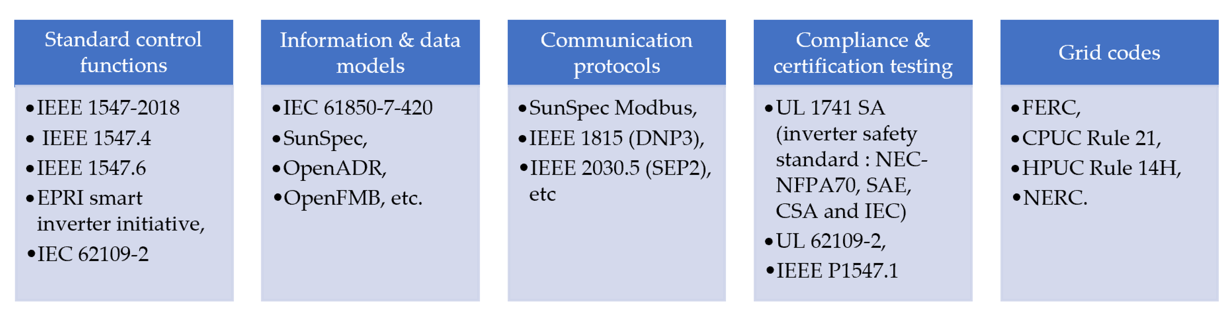
In Figure 29, the authors specify the double stage fly-back microinverter with soft switching. The first stage is to boost the DC voltage level and the second stage fed AC power to the AC grid. The energy stored in coupling capacitor C2 is released to primary winding through switch S2 and delivered to a grid-connected system. The voltage level caused is presented at the first stage of capacitor C2 and reduces the value of the capacitor. The efficiency of the system is up to 85% [55].
In Figure 30 the authors specified the three-stage power inverter. In this topology, the circuit consists of a full-bridge with a combined buck converter through a high-frequency transformer presented in [56]. The buck converter is assigned to form the grid current injection on the inverter side to achieve the rectified sine wave. The phase shift PWM controller achieves ZVS by minimizing switching losses. Long-life film capacitors are being used in place of unreliable aluminum electrolytic capacitors in the high voltage DC connection. The overall efficiency is approximately 89%, with an MPPT efficiency of approximately 99%.
In Figure 31 authors specified the boost half-bridge converter with full-bridge inverter presented in [57]. The current controller based on a linear phase Infinite Impulse Response (IIR) filter is realized to obtain the high-power factor and low THD of voltage and current. The efficiency of this converter is about 97–98%, and the overall efficiency is reduced due to its frequent switching losses.
In Figure 32 the authors present the dual-boost converter with a full-bridge inverter in [58]. The PV voltage is directly fed to the input of interleaved dual boost converter. Energy obtained from the PV is first stored in inductors L1 and L2 and delivered to the voltage doubler capacitor via a transformer.
The energy stored in buck inductor Lb is realized to diode Db when the AC grid voltage is lesser than the input voltage. The overall efficiency is about 93%, with an MPPT accuracy of 0.93. The overall cost of the system is high due to the usage of a large number of components. In Figure 33 authors proposed the current-push pull converter with a full bride inverter [59].
The parallel capacitor and transformer secondary leakage reactance form an LC resonance circuit. Soft-switching is achieved by turn-on ZVS and turn off ZCS for certain operating conditions. This system has an efficiency of 97.5% at high power. In Figure 34 authors proposed the new Hybrid resonant DC-DC converter with soft switching. Hybrid DC–DC converter consisting of bi-directional GAN switch parallel to the high-frequency transformer and DC link capacitors [60].
The converter operates in three modes pure buck-boost series resonant modes. With the proper design of transformer inductance Lm under certain operating conditions, the primary side of MOSFETs can achieve ZVS near zero current switching (ZCS). The overall efficiency of the system is about 97% at high power. In Figure 35 the authors propose an active clamp DC–DC converter with a single switch modulated inverter. It can achieve ZVS by recycling the energy stored in the leakage inductance of the transformer [61].
The series resonant voltage doubler at the secondary side achieves ZCS turnoff of the rectifier diode, and reverse recovery loss can be eliminated. Because of a single switch module, higher efficiency and reliability can be achieved. The overall efficiency can be obtained up to 96% with a THD of 3.8%. In Figure 36, the authors propose the fly-back inverter with HFAC-link and active decoupling circuit. In this system, the active decoupling circuit replaces the electrolytic capacitor with a film capacitor proposed. This proposed model achieves the ZCS of the transistor in the decoupling circuit and output stage of converter. Due to hard switching on the primary side and fly back in the decoupling circuit may reduce the overall performance of the system presented in [62].
In Figure 37 the authors specify the full-bridge resonant converter with a three-phase inverter circuit. In the first stage, full-bridge LLC (inductor–inductor–capacitor) resonant DC–DC converter with MPPT, and in the second stage DC link capacitor, a three-phase inverter with the resonant circuit is presented in [63,64]. Thus, a bi-directional inductor current can achieve the ZVS, and the converter does not require any auxiliary circuit for soft switching. The efficiency is about 96%. Due to the use of a thin DC-link film capacitor, the life span is long and which makes the system good is suitable for three-phase solar PV farms. The comparison of multi-stage isolated PV micro-inverter summarized in Table 5 and Table 6 shows the different single phase inverter control techniques and their features.

6. Smart Inverter

The smart inverter has increased in popularity in the field, and it now demands a digital architecture, multimodal communications functionality, and reliable computing infrastructure. The device starts with silicon-centric hardware that is stable, rugged, and powerful and can be managed by a flexible software interface with comprehensive performance management capabilities. A smart inverter must be adaptable and capable of easily sending and receiving messages, as well as sharing granular data with the user, utility, and other stakeholders. Installers and repair technicians may use such systems to detect operating and maintenance concerns, as well as anticipate potential inverter or module issues and remotely update those parameters in seconds. These intelligent power electronics systems must also have a robust application programming interface (API) that allows fleet owners and other collaborators to integrate their applications and build effective enterprise-level tools.
Although the digital architecture, bidirectional connectivity, and software infrastructure technology that underpin smart inverters are crucial, the organizations that deliver such advanced solutions must also work on modern utility specifications and standards in a smart way (Figure 38). Such collaborative projects as the continuing UL/ANSI 1741 and IEEE 1547 standards progress work, as well as the Smart Inverter Working Group, will help ensure the proper deployment of advanced grid functionality needed for the more solarized energy mix of the not-too-distant future.
The smart online tracking and fault detection system is compatible with intelligent Internet of Things (IoT) devices and can be accessed from a personal computer (PC) or an Android/iOS app. Users can capture real-time data, analyze historical data, compare patterns across various dimensions, and export graphs. Furthermore, users will be alerted via SMS/email if the platform detects any faults, trouble areas, or breakdowns. Users and suppliers may use these intelligent management platforms to efficiently and effectively track errors in real time, ensuring optimal results. It helps you solve efficiency problems by achieving full power output against faulty and dusty panels. The alarms created by the panel are a true lifesaver in situations like the output below simple limits or a specific type of misfiring (Figure 39).
Smart inverters have a positive impact on both the residential sector and the national power grid because they operate independently. The traditional grid needs constant maintenance, but smart inverters may be able to help fix these localized issues and increase the system flexibility. The smart inverter functions such as fault detection, islanding detection, and power flow control [65,66,67,68]. Figure 40 illustrated the main function smart inverter.
Smart inverters are a combination of conventional inverters that are interfaced with renewable energy sources such as PV, wind, and plug-in electric vehicles with advanced controllers for performing ancillary services such as reactive power-sharing and Var management. As a result, it is also known as a multifunctional or intelligent hybrid inverter. The role of a multifunctional inverter exceeds the basic functionalities of traditional inverters, such as power conversion, maximum power point tracking, and islanding detection. The government, utilities, industries, and standard bodies have collaborated to create common, standardized control functionalities for integrating renewable energy sources with the power system. The smart inverter standards are given in Figure 41.
The distributed energy resources penetration level directly links power quality to the smart inverter, with higher penetration levels resulting in a stronger coupling between grid power quality and the smart inverter. The smart inverter may operate in a different mode of operation such as isochronous operation, droop control mode, grid following the operation, and micro-grid operation. The following are the specific changes in the power quality-related limits that are effective for smart inverters such as rapid voltage change, flicker, harmonic current distortion, and overvoltage contribution.

7. Conclusions

A study of inverter structure was discussed, with an emphasis on state-of-the-art configurations such as single-stage and double-stage inverters. In addition, transformerless inverter configurations play a prominent part in PV-based power generation. These inverter types are discussed together with a qualitative assessment of the inverters. The structural and practical advantages/issues of each topology are discussed in depth. There was also a comparison of such architectures. For the efficient integration of PVs with the utility grid in the future, a simple perception of power converters would be needed. Meeting the grid-connected specifications becomes a big obstacle as well. As a result, the synchronization between the inverter and the grid was explored in this article, to highlight core principles in grid synchronization. Finally, smart inverters were surveyed and explored from various developed works. An analysis of numerous studies in the literature has been given to provide researchers with a detailed description of all potential inverter architectures.
From the above review, it has been concluded that the average efficiency of a solar PV system is likely to increase in the coming years and the price will also be reduced. This analysis will assist technicians in choosing the best and correct control and inverter configuration, as per basic power specifications, position, and the ability for grid communication. The study is also projected to benefit designers, analysts, suppliers, and consumers involved in the area of solar energy for the improvement of the exploitation and grid incorporation of solar energy. It also lets you choose the right configuration for your specific system.

Author Contributions

Conceptualization, I.V. and P.J.P.; methodology, I.V. and R.K.K.; software, V.V.; formal analysis, P.J.P. and S.V.; investigation, I.V. and L.R., writing—original draft preparation, I.V., L.R. and S.V.; writing—review and editing, I.V. and V.V.; visualization, R.K.K. and S.V.; supervision, I.V., L.R. and S.V. All authors have read and agreed to the published version of the manuscript.

Funding

This research received no external funding.

Conflicts of Interest

The authors declare no conflict of interest.

References

  1. Babu, T.S.; Rajasekar, N.; Sangeetha, K. Voltage band based improved particle swarm optimization technique for maximum power Point tracking in solar photovoltaic system. Renew. Sustain. Energy Rev. 2016, 15, 60–70. [Google Scholar]
  2. Babu, T.S.; Rajasekar, N.; Sangeetha, K. Modified particle swarm optimization technique based maximum power point tracking for uniform and under partial shading condition. Appl. Soft Comput. 2015, 32, 613–624. [Google Scholar] [CrossRef]
  3. Ram, J.P.; Babu, T.S.; Rajasekar, N. A comprehensive review on solar PV maximum power point tracking techniques. Renew. Sustain. Energy Rev. 2017, 67, 826–847. [Google Scholar] [CrossRef]
  4. Yang, Z.; Sen, P.C. A novel switch-mode dc-to-ac inverter with nonlinear robust control. IEEE Trans. Ind. Electron. 1998, 45, 602–608. [Google Scholar] [CrossRef]
  5. Kim, J.K.; Moon, G.W. Derivation, analysis, and comparison of non-isolated single switch high step-up converters with low voltage stress. IEEE Trans. Power Electron. 2015, 30, 1336–1344. [Google Scholar] [CrossRef]
  6. Balaji, C.; Chellammal, N.; Subranshu, S.D. A Non isolated Three-Port DC–DC Converter with Continuous Input and Output Currents Based on Cuk Topology for PV/Fuel Cell Applications. Electronics 2019, 8, 214. [Google Scholar]
  7. Wang, B.; Sechilariu, M.; Locment, F. Intelligent DC micro grid with smart grid communications: Control strategy consideration and design. IEEE Trans. Smart Grid 2012, 3, 2148–2156. [Google Scholar] [CrossRef]
  8. Veneri, O.; Capasso, C.; Lannuzzi, D. Experimental evaluation of DC charging architecture for fully-electrified low-power two-wheeler. Appl. Energy 2016, 162, 1428–1438. [Google Scholar] [CrossRef]
  9. Sun, Y.; Zhong, C.; Hou, X.; Yang, J.; Han, H.; Guerrero, G.M. Distributed cooperative synchronization strategy for multi-bus microgrids. Int. J. Electr. Power Energy Syst. 2017, 86, 18–28. [Google Scholar] [CrossRef] [Green Version]
  10. Li, W.; He, X. Review of non-isolated high step-up DC/DC converters in photovoltaic grid-connected applications. IEEE Trans. Ind. Electron. 2011, 58, 1239–1250. [Google Scholar] [CrossRef]
  11. Davis, R.; Aathira, K.V. Developed non-isolated high step-up converter with low voltage stress. In Proceedings of the 2016 International Conference on Electrical, Electronics, and Optimization Techniques (ICEEOT), Chennai, India, 3–5 March 2016; pp. 1537–1540. [Google Scholar] [CrossRef]
  12. Teodorescu, R.; Blaabjerg, F.; Liserre, M.; Loh, P. Proportional resonant controllers and filters for grid-connected voltage-source converters. IEEE Electr. Power Appl. 2006, 153, 750–762. [Google Scholar] [CrossRef] [Green Version]
  13. Blaabjerg, F.; Chen, Z.; Kjaer, S.B. Power electronics as efficient inter power generation systems. IEEE Trans. Power Electron. 2004, 19, 1184–1194. [Google Scholar] [CrossRef]
  14. Prabaharan, N.; Palanisamy, K. Analysis and integration of multilevel inverter configuration with boost converters in a photovoltaic system. Energy Convers Manag. 2016, 128, 327–342. [Google Scholar] [CrossRef]
  15. Kasa, N.; Iida, T.; Iwamoto, H. An inverter using buck-boost type chopper circuits for popular small-scale photovoltaic power system. In Proceedings of the IEEE IECON’99, San Jose, CA, USA, 29 November–3 December 1999; pp. 185–190. [Google Scholar]
  16. Nagao, M.; Harada, K. Power flow of photovoltaic system using buck-boost PWM power inverter. In Proceedings of the IEEE PEDS’97, Singapore, 26–29 May 1997; pp. 144–149. [Google Scholar]
  17. Rahman, M.F.; Zhong, L. A new, transformerless, photovoltaic array to utility grid interconnection. In Proceedings of the Second International Conference on Power Electronics and Drive Systems, Singapore, 26–29 May 1997; pp. 139–143. [Google Scholar]
  18. Veerachary, V.; Senjyu, T.; Uezato, K. Neural-network-based maximum-power-point tracking of coupled-inductor interleaved-boost-converter-supplied PV system using fuzzy controller. IEEE Trans. Ind. Electron. 2003, 50, 749–758. [Google Scholar] [CrossRef] [Green Version]
  19. Hsieh, Y.; Chen, J.; Liang, T.; Yang, L. Novel High Step-Up DC–DC Converter with Coupled-Inductor and Switched-Capacitor Techniques. IEEE Trans. Ind. Electron. 2012, 59, 998–1007. [Google Scholar] [CrossRef]
  20. Akkaya, R.; Kulaksız, A.A.; Aydoğdu, Ö. DSP implementation of a PV system with GA-MLP-NN based MPPT controller supplying BLDC motor drive. Energy Convers. Manag. 2007, 48, 210–218. [Google Scholar] [CrossRef]
  21. Choi, S.; Agelidis, V.G.; Yang, J.; Coutellier, D.; Marabeas, P. Analysis, design and experimental results of a floating-output interleaved-input boost-derived DC–DC high-gain transformer-less converter. IET Power Electron. 2011, 4, 168–180. [Google Scholar] [CrossRef]
  22. Cáceres, R.O.; Barbi, I. A boost dc-ac converter: Analysis, design, and experimentation. IEEE Trans. Power Electron. 1999, 14, 134–141. [Google Scholar] [CrossRef]
  23. Ashraf Gandomi, A.; Varesi, K.; Hosseini, S.H. “DC-AC buck and buck-boost inverters for renewable energy applications. In Proceedings of the 6th Power Electronics, Drive Systems & Technologies Conference (PEDSTC2015), Tehran, Iran, 3–4 February 2015; pp. 77–82. [Google Scholar] [CrossRef]
  24. Suroso; Winasis; Priswanto; Purnama, I.D. Design of 1 kW Buck-Boost Chopper with PI Control for Photovoltaic Power Conversion. IOP Conf. Series Mater. Sci. Eng. 2020, 982, 012022. [Google Scholar] [CrossRef]
  25. Wang, X.; Xiao, H.; Wei, Z.; Chen, C. An Improved Transformerless Photovoltaic Grid-Connected Soft-Switching Inverter. In Proceedings of the 14th IEEE Conference on Industrial Electronics and Applications (ICIEA), Xi’an, China, 19–21 June 2019; pp. 2338–2343. [Google Scholar] [CrossRef]
  26. Shen, J.-M.; Jou, H.-L.; Wu, J.-C. Novel Transformerless Grid-Connected Power Converter with Negative Grounding for Photovoltaic Generation System. IEEE Trans. Power Electron. 2012, 27, 1818–1829. [Google Scholar] [CrossRef]
  27. Duran-Gomez, J.L.; Garcia-Cervantes, E.; Lopez-Flores, D.R.; Enjeti, P.N.; Palma, L. Analysis and evaluation of a series-combined connected boost and buck-boost dc-dc converter for photovoltaic application. In Proceedings of the Twenty-First Annual IEEE Applied Power Electronics Conference and Exposition, APEC ’06, Dallas, TX, USA, 19–23 March 2006; pp. 19–23. [Google Scholar]
  28. Mallwitz, R. Circuit Apparatus for Transformerless Conversion of an Electric Direct Voltage into an Alternating Voltage. U.S. Patent 7,616,467, 10 November 2009. [Google Scholar]
  29. Zacharias, P.; Sahan, B. Device for Feeding Electric Energy into A power Grid and DC Converter for such a Device. U.S. Patent 8116103 B2, 14 February 2012. [Google Scholar]
  30. Araujo, S.V.; Zacharias, P.; Sahan, B. Novel grid-connected non isolated converters for photovoltaic systems with grounded generator. In Proceedings of the 2008 IEEE Power Electronics Specialists Conference, Rhodes, Greece, 15–19 June 2008; pp. 58–65. [Google Scholar]
  31. Schoenbauer, S.; Martin-Lopez, F.R. Single Inductor Buck Boost Converter with Positive and Negative Outputs. U.S. Patent 2010/0039080, 18 February 2010. [Google Scholar]
  32. Prasad, S.; Jain, S.; Agarwal, V. Universal single-stage grid connected inverter. IEEE Trans. Energy Convers. 2008, 23, 128–137. [Google Scholar] [CrossRef]
  33. Junior, L.G.; de Brito, M.A.G.; Sampaio, L.P.; Canesin, C.A. Single stage converters for low power stand-alone and grid-connected PV systems. In Proceedings of the 2011 IEEE International Symposium on Industrial Electronics, Gdansk, Poland, 27–30 June 2011; pp. 1112–1117. [Google Scholar]
  34. Nahavandi, A.; Roostaee, M.; Azizi, M.R. Single stage DC-AC boost converter. In Proceedings of the 7th Power Electronics and Drive Systems Technologies Conference (PEDSTC), Tehran, Iran, 16–18 February 2016; pp. 362–366. [Google Scholar] [CrossRef]
  35. Liang, T.; Shyu, J.; Chen, J. A novel DC/AC boost inverter. In Proceedings of the 2002 37th Intersociety Energy Conversion Engineering Conference, Washington, DC, USA, 29–31 July 2002; pp. 629–634. [Google Scholar]
  36. Swaminathan, N.; Lakshminarasamma, N. High Gain, High Frequency Link DC-AC Converter with Hybrid SPWM Scheme. In Proceedings of the 2018 IEEE International Conference on Power Electronics, Drives and Energy Systems (PEDES), Madras, India, 18–21 December 2018; pp. 1–6. [Google Scholar] [CrossRef]
  37. Vazquez, N.; Almazan, J.; Alvarez, J.; Aguilar, C.; Arau, J. Analysis and experimental study of the buck, boost and buck-boost inverters. In Proceedings of the 30th Annual IEEE Power Electronics Specialists Conference. Record. (Cat. No.99CH36321), Charleston, SC, USA, 1 July 1999; pp. 801–806. [Google Scholar]
  38. Kasa, N.; Ogawa, H.; Iida, T.; Iwamoto, H. A transformer-less inverter using buck-boost type chopper circuit for photovoltaic power system. In Proceedings of the IEEE 1999 International Conference on Power Electronics and Drive Systems, Hong Kong, China, 27–29 July 1999; pp. 653–658. [Google Scholar]
  39. Patel, H.; Agarwal, V. A single-stage single-phase transformer-less doubly grounded grid-connected PV interface. IEEE Trans. Energy Convers. 2009, 24, 93–101. [Google Scholar] [CrossRef]
  40. Kusakawa, M.; Nagayoshi, H.; Kamisako, K.; Kurokawa, K. Further improvement of a transformerless, voltage-boosting inverter for AC modules. Solar Energy Mater. Solar Cells 2001, 67, 379–387. [Google Scholar] [CrossRef]
  41. Cao, D.; Jiang, S.; Yu, X.; Peng, F.Z. Low-cost semi-Z-source inverter for single-phase photovoltaic systems. IEEE Trans. Power Electron. 2011, 26, 3514–3523. [Google Scholar] [CrossRef]
  42. Li, D.; Loh, P.C.; Zhu, M.; Gao, F.; Blaabjerg, F. Generalized multi cell switched-inductor and switched-capacitor Z-source inverters. IEEE Trans. Power Electron. 2013, 28, 837–848. [Google Scholar] [CrossRef]
  43. Kjaer, S.B.; Pedersen, J.K.; Blaabjerg, F. A review of single-phase grid-connected inverters for photovoltaic modules. IEEE Trans. Ind. Appl. 2005, 41, 1292–1306. [Google Scholar] [CrossRef]
  44. Kasa, N.; Iida, T.; Chen, L. Fly-back inverter controlled by sensorless current MPPT for photovoltaic power system. IEEE Trans. Ind. Electron. 2005, 52, 1145–1152. [Google Scholar] [CrossRef]
  45. Shimizu, T.; Wada, K.; Nakamura, N. Flyback type single-phase utility-interactive inverter with power pulsation decoupling on the DC input for an AC photovoltaic module system. IEEE Trans. Power Electron. 2006, 21, 1264–1272. [Google Scholar] [CrossRef]
  46. Hu, H.B.; Harb, S.; Fang, X.; Zhang, D.H.; Zhang, Q.; Shen, Z.J. A three-port flyback for PV micro inverter applications with power pulsation decoupling capability. IEEE Trans. Power Electron. 2016, 27, 3953–3964. [Google Scholar] [CrossRef]
  47. Hu, H.B.; Harb, S.; Kutkut, N.H.; Shen, Z.J.; Batarseh, I. A single-stage micro inverter without using electrolytic capacitors. IEEE Trans. Power Electron. 2013, 28, 2677–2687. [Google Scholar] [CrossRef]
  48. Sukesh, N.; Pahlevaninezhad, M.; Jain, P.K. Analysis and implementation of a single-stage flyback PV micro inverter with softswitching. IEEE Trans. Ind. Electron. 2014, 61, 1819–1833. [Google Scholar] [CrossRef]
  49. Zhang, Z.L.; He, X.F.; Liu, Y.F. An optimal control method for photovoltaic grid-tied interleaved flyback micro inverters to achieve high efficiency in wide load range. IEEE Trans. Power Electron. 2013, 28, 5074–5087. [Google Scholar] [CrossRef]
  50. Edwin, F.F.; Xiao, W.; Khadkikar, V. Dynamic modelling and control of interleaved flyback module-integrated converter for PV power applications. IEEE Trans. Ind. Electron. 2014, 61, 1377–1388. [Google Scholar] [CrossRef]
  51. Pathy, S.; Sridhar, R.; Hari, N.; Dash, S.S.; Subramani, C. A modified module integrated—Interleaved boost converter for standalone photovoltaic (PV) application. In Proceedings of the 2016 IEEE International Conference on Renewable Energy Research and Applications (ICRERA), Birmingham, UK, 20–23 November 2016; pp. 989–994. [Google Scholar] [CrossRef]
  52. Gao, M.; Chen, M.; Zhang, C.; Qian, Z. Analysis and implementation of an improved flyback inverter for photovoltaic AC module applications. IEEE Trans. Power Electron. 2013, 28, 2649–2663. [Google Scholar] [CrossRef]
  53. Kim, Y.-H.; Ji, Y.-H.; Kim, J.-G.; Jung, Y.-C.; Won, C.-Y. A new control strategy for improving weighted efficiency in photovoltaic AC module-type interleaved flyback inverters. IEEE Trans. Power Electron. 2013, 28, 2688–2699. [Google Scholar] [CrossRef]
  54. Meneses, D.; Garcia, O.; Alou, P.; Oliver, J.; Cobos, J. Grid-connected forward microinverter with primary- parallel secondary-series transformer. IEEE Trans. Power Electron. 2015, 30, 4819–4830. [Google Scholar] [CrossRef] [Green Version]
  55. Tan, G.H.; Wang, J.Z.; Ji, Y.C. Soft-switching flyback inverter with enhanced power decoupling for photo voltaic applications. IET Electron. Power Appl. 2017, 1, 264–274. [Google Scholar] [CrossRef]
  56. Rodriguez, C.; Amaratunga, G.A. Long-life time power inverter for photovoltaic AC modules. IEEE Trans. Ind. Electron. 2008, 55, 2593–2601. [Google Scholar] [CrossRef]
  57. Jiang, S.; Cao, D.; Li, Y.; Peng, F.Z. Grid-connected boost-half-bridge photovoltaic micro inverter system using repetitive current control and maximum power point tracking. IEEE Trans. Power Electron. 2012, 27, 4711–4722. [Google Scholar] [CrossRef]
  58. Chiu, H.J.; Lo, Y.K.; Yang, C.Y.; Cheng, S.J.; Huang, C.M.; Chuang, C. C A module integrated isolated solar micro inverter. IEEE Trans. Ind. Electron. 2013, 60, 781–788. [Google Scholar] [CrossRef]
  59. Kim, Y.-H.; Shin, S.-C.; Lee, J.-H.; Jung, Y.-C.; Won, C.-Y. Soft-switching current-fed push–pull converter for 250W AC module applications. IEEE Trans. Power Electron. 2014, 29, 863–872. [Google Scholar]
  60. LaBella, T.; Lai, J.S. A hybrid resonant converter utilizing a bidirectional GaNAC switch for high-efficiency PVapplications. IEEE Trans. Ind. Electron. 2015, 50, 3468–3475. [Google Scholar]
  61. Cha, W.J.; Cho, Y.W.; Kwon, J.M.; Kwon, B.H. Highly efficient micro inverter with soft- switching step-up converter and single-switch-modulation inverter. IEEE Trans. Ind. Electron. 2015, 62, 3516–3523. [Google Scholar]
  62. Korosec, L.; Konjedic, T.; Truntic, M.; Rodic, M.; Milanovic, M. PDM flyback PV micro inverter with HFAC-link and active de coupling circuit. Electron. Lett. 2015, 51, 516–517. [Google Scholar] [CrossRef]
  63. Chen, L.; Amirahmadi, A.; Zhang, Q.; Kutkut, N.; Batarseh, I. Design and implementation of three-phase two-stage grid-connected module integrated converter. IEEE Trans. Power Electron. 2013, 29, 3881–3892. [Google Scholar] [CrossRef]
  64. Arbab-Zavar, B.; Palacios-Garcia, E.J.; Vasquez, J.C.; Guerrero, J.M. Smart Inverters for Microgrid Applications: A Review. Energies 2019, 12, 840. [Google Scholar] [CrossRef] [Green Version]
  65. From Smart Meters to Smart Inverters: How DVI Is Optimizing the Distributed Grid Greentechmedia.com. 2018. Available online: https://www.greentechmedia.com/articles/read/DVIs-grid-edge-vision-from-smart-meters-to-smart-inverters (accessed on 15 April 2021).
  66. Xue, Y.; Guerrero, J.M. Smart inverters for utility and industry applications. In Proceedings of the PCIM Europe 2015, International Exhibition and Conference for Power Electronics, Intelligent Motion, Renewable Energy and Energy Management, Nuremberg, Germany, 19–20 May 2015; pp. 1–8. [Google Scholar]
  67. Mirafzal, B.; Adib, A. On grid-interactive smart inverters: Features and advancements. IEEE Access 2020, 8, 160526–160536. [Google Scholar] [CrossRef]
  68. Lulbadda, K.T.; Hemapala, K.T.M.U. The additional functions of smart inverters. Aims Energy 2019, 7, 971–988. [Google Scholar] [CrossRef]
Figure 1. Inverter applications.
Electronics 10 01296 g001
Figure 2. Block diagram of standalone photovoltaic (PV) system.
Electronics 10 01296 g002
Figure 3. Block diagram of converter and inverter-based on solar PV system.
Electronics 10 01296 g003
Figure 4. Comparison of PV inverter.
Electronics 10 01296 g004
Figure 5. Micro-inverter.
Electronics 10 01296 g005
Figure 6. Block diagram of two-stage topology transformerless inverter.
Electronics 10 01296 g006
Figure 7. Boost converter full bridge transformerless inverter.
Electronics 10 01296 g007
Figure 8. Period sharing boost converter with full-bridge transformerless inverter.
Electronics 10 01296 g008
Figure 9. Soft switched parallel resonant boost converter and full-bridge inverter.
Electronics 10 01296 g009
Figure 10. Boost converter and transformerless half-bridge inverter.
Electronics 10 01296 g010
Figure 11. Boost with feedback integrated and dual grounded transformerless inverter.
Electronics 10 01296 g011
Figure 12. Block diagram of a single-stage topology for an alternating current (AC) module.
Electronics 10 01296 g012
Figure 13. Universal single-stage grid-connected inverter.
Electronics 10 01296 g013
Figure 14. Integrated boost inverter.
Electronics 10 01296 g014
Figure 15. Integrated buck-boost inverter.
Electronics 10 01296 g015
Figure 16. Boost inverter with improved zero crossing.
Electronics 10 01296 g016
Figure 17. Differential boost inverter.
Electronics 10 01296 g017
Figure 18. Two-sourced anti-parallel buck-boost inverter.
Electronics 10 01296 g018
Figure 19. Single phase Z-source inverter.
Electronics 10 01296 g019
Figure 20. Single stage fly-back inverter.
Electronics 10 01296 g020
Figure 21. Single stage fly-back inverter with decoupling circuit.
Electronics 10 01296 g021
Figure 22. Three port fly-back inverter with coupling circuit-1.
Electronics 10 01296 g022
Figure 23. Three port fly-back inverter with coupling circuit-2.
Electronics 10 01296 g023
Figure 24. Single stage fly-back inverter with soft switching.
Electronics 10 01296 g024
Figure 25. Single phase two-phase interleaved fly-back converter.
Electronics 10 01296 g025
Figure 26. CCM control interleaved fly-back converter.
Electronics 10 01296 g026
Figure 27. Interleaved fly-back inverter with soft switching.
Electronics 10 01296 g027
Figure 28. Primary parallel secondary series multi-core inverter.
Electronics 10 01296 g028
Figure 29. Double stage fly-back inverter with soft switching.
Electronics 10 01296 g029
Figure 30. Three stage fly-back inverter with soft switching.
Electronics 10 01296 g030
Figure 31. Boost half-bridge converter with full bridge inverter.
Electronics 10 01296 g031
Figure 32. Dual boost converter with full bridge inverter.
Electronics 10 01296 g032
Figure 33. Current fed push-pull converter with full bridge inverter.
Electronics 10 01296 g033
Figure 34. Hybrid resonant DC–DC converter with soft switching.
Electronics 10 01296 g034
Figure 35. Active clamp DC–DC converter with single switch modulated inverter.
Electronics 10 01296 g035
Figure 36. Fly-back converter with High Frequency AC linked active decoupling circuit.
Electronics 10 01296 g036
Figure 37. Full bridge resonant converter with three phase inverter.
Electronics 10 01296 g037
Figure 38. Smart inverter features.
Electronics 10 01296 g038
Figure 39. Smart PV system with inverter.
Electronics 10 01296 g039
Figure 40. Smart inverter functions.
Electronics 10 01296 g040
Figure 41. Smart inverter standards and grid codes.
Electronics 10 01296 g041
Table 1. Comparative study on ratings of two-stage inverter topologies.
FigureVinVout (Vrms)Power RatingFrequencySwitching TimingEfficiency
Figure 71602101500200.0594
Figure 81402001600200.0596.5
Figure 9160120270300.033-
Figure 101202309806.260.15-
Figure 11150115930180.05596.7
Table 2. Comparative study on ratings of single-stage inverter topologies.
FigureVinVoutPower RatingFrequencySwitching TimingEfficiency
Figure 1250100150100.1-
Figure 1316.8110200100.170
Figure 1420230170100.185
Figure 15200–3502301000--93.6
Figure 1660–75120180150.15-
Figure 1750120200--75
Figure 1840–5090–1105009.20.09280–90
Figure 1950–25012095050.05-
Figure 20150120200200.294–95
Table 3. Comparison of single-stage isolated PV inverter.
FigurePowerMode of OperationNumber of SwitchesCostTHDEfficiencyLife Span
Figure 21300DCM3Low-89.1Short
Figure 22100DCM4Medium-70.2Long
Figure 23100DCM4Medium<1.7%90.51Long
Figure 24100Modified DCM4Medium<1.9%90.12Long
Figure 252502φAnd
1φDCM
3Low-94.1Short
Figure 26200DCM6Medium<3.79%94.21Short
Figure 27200CCM6Medium<4%95.1Short
Figure 28200BCM6Medium<2.46%94.2Short
Figure 29250DCM8Medium-95.1Short
Table 4. Merits and demerits of the various single stage topologies.
TopologyMeritsDemeritsReference
BoostHigh gain, low Total Harmonic Distortion Less efficiency, high switching losses, and high voltage and current stresses[32,33]
Buck-BoostHigh gain, the dead time during Pulse Width Modulation (PWM) eliminated, common-mode leakage current removedIncreased inductor size, High current stress on inductors[34,36,39]
Z sourceHigh gainhigh conduction losses and voltage stresses, expensive[41]
Fly-backAvailability of galvanic isolation, eliminate power pulsation,High Electro Magnetic Interference (EMI), low efficiency, increased cost, size, and weight[43]
Table 5. Comparison of multi-stage isolated PV micro inverter.
FigurePowerMode of OperationNumber of SwitchesCostTHDEfficiencyLife Span
Figure 32500DCM4Medium<1.7%90.1Long
Figure 33150-9High<1.9%90Long
Figure 34210-6High-94.1Long
Figure 35250-7High<3.79%94.1Short
Figure 36250-6High<4%95.4Short
Figure 37400-6High<2.46%94.1Short
Figure 38100-6High-95.1Short
Table 6. Control techniques and their features.
TopologyControllerApplication
Full bridgeDeadbeatUninterrupted Power Supply (UPS)
Two-stage half-bridge inverterProportional-Resonant (PR) current controlFuel cell
Z source inverterRepetitive, PR current control, Selective compensator, Capacitor current, Droop control, Fractional-order repetitive controlDistributed Generation (DG), UPS, PV and Wind
Publisher’s Note: MDPI stays neutral with regard to jurisdictional claims in published maps and institutional affiliations.

