Abstract
This paper proposed a novel antenna for ultra-high frequency (UHF) radio frequency identification (RFID) near-field applications with uniform distribution of the electric field along the x-axis (Ex), and the y-axis (Ey). The proposed antenna adopted a spiral structure to achieve broadband and multi-polarization. The novel antenna achieved good impedance matching within 860–960 MHz. Using a ground plate, the proposed antenna achieved low far-field gain and a maximum gain of less than −11 dBi. The component of the excited electric field Ex and Ey parallel to the antenna surface was uniformly distributed, and there was no zero point. The proposed antenna achieved a 100% read rate of tags parallel to its surface in the reading area of 150 mm × 150 mm × 220 mm. Simulation results were consistent with the results of real-world measurements, and the proposed antenna was suitable as a reader antenna in near-field applications. The polarization mode of RFID tags is mostly linear polarization, and the placement of tags in practical applications is diversified. Compared with the traditional RFID reader antenna, the proposed antenna achieves uniform electric field distribution parallel to the antenna surface, but the single-direction electric field has zero-reading points, which is easy to cause the misread of tags. The RFID tags can be read more accurately. To verify the scalability of the reading area of the spiral antenna unit, it was used for array design, and simulations were conducted using 1 × 2, 2 × 2, 1 × 4, and 2 × 4 arrays. The component distribution of the electric field excited by the four array antennas in the x and y directions was uniform and the reading area was controllable. Therefore, the proposed spiral antenna has the expandability of the reading area and can meet the needs of different application scenarios by changing the number of array units. With the array extension, the matching network also extends, and the impedance characteristics of the array antenna are somewhat different, but they also meet the application requirements.
1. Introduction
Radio frequency identification (RFID) uses radio signals to identify specific targets. RFID operates using a reader antenna to remotely track objects through an RFID tag attached to the object, as well as recognize and store relevant information about objects in order to realize item tracking and real-time monitoring. RFID has been widely adopted because of its no-contact, reliable communication; automatic recognition of moving targets; and quick reading and writing capabilities. It is widely used in freight, retail, indoor positioning, access control management, identity identification, etc. RFID used in far-field applications can identify RFID tags at long distance, but it is easy to misread other tags in near-field. RFID used in near-field applications can accurately and stably identify RFID tags and not miss reading other tags at a long distance. With the increasing demand for RFID near-field applications, it is important to conduct research into near-field RFID [1,2,3]. In the practical application of RFID tags, the placement of tags is diverse. To achieve uniform and stable reading of tags, the horizontal field uniformity of the antenna is required to be relatively high and its distribution is required to be uniform. The research on antennas that realize uniform field distribution in the near field of RFID mainly realizes uniform distribution of the composite field in the horizontal direction. There are zero points in the field distribution in a single direction in the horizontal plane, and the field is not uniform. Thus, the research on RFID near-field applications with uniform distribution of the electric field along the x-axis (Ex) and the y-axis (Ey) is important. Depending on electromagnetic field coupling, reader antennas for RFID near-field applications can be based on magnetic field coupling and electric field coupling. Reader antennas, which are based on magnetic field coupling, induce current through an alternating magnetic field to activate loop tags. Common antennas for magnetic field coupling are loop structure antennas [4,5,6,7,8,9,10,11,12,13], reconfigurable modular antennas [14,15], and array antennas [16,17,18]. The loop is made up of a typical magnetic coupling antenna, which includes a large loop antenna and a small loop periodic antenna. Large loop antennas are generally designed to be larger in size in order to achieve a larger reading area. Current inversion on the loop must be resolved in order to achieve a strong and uniform magnetic field distribution. Contemporary methods for achieving current inversion involve loading capacitors [1,2], segmented lines [3], phase shifters [4], and zero-phase-shifting loop antennas [5,6,7,8,9,10]. Large loop antennas are characterized by strong and uniform magnetic field distribution, high reading accuracy, high system reliability, and high gain in the far-field antenna. It is easy to misread labels outside the reading area of large loop antennas due to double-sided radiation. Antennas that are periodically arranged with small loops as units [11,12] use the superposition of magnetic fields between the small loops to achieve uniform magnetic field distribution in the reading area. This kind of antenna is characterized by low gain, difficulty in misreading tags outside the reading area, and the ability to adjust the number of units according to application requirements in order to achieve expansion of the reading area. Reader antennas, which are based on electric field coupling, activate tags through an electromotive force induced by an alternating electric field. The reading distance is longer than the magnetic field coupling. Common antennas for electric field coupling include traveling-wave antennas, standing-wave antennas, circularly polarized antennas, and multi-polarized antennas. The general form of the traveling wave reader antenna [19] is that the terminal is connected to a matched load, the current changes with time, no current is reflected, and a wide impedance bandwidth is achieved. The standing wave reader antenna generally has an open terminal [20]. The current is a standing wave distribution and has fixed wave nodes and anti-nodes. The radiation field of the standing wave of the reader antenna is easier to control than that of the traveling-wave antenna; however, the impedance bandwidth of the standing wave is relatively narrow. Due to the reflection effect of current in the standing-wave antenna, the reflected wave is opposite to the incident wave at λ/2 from the terminal antenna, and both waves cancel each other out. The reflected wave and incident wave are in phase and superimposed at λ/4; therefore, stripline antennas cannot avoid zero points. A common solution to this problem is to increase bending in order to reduce the influence of the current wave node [21]. The electric field coupling reader antenna considers the direction of polarization in the reader antenna and the tag antenna. The reader antenna and the tag antenna cannot receive RF signals from each other when the directions of polarization in both antennas are perpendicular. In practical applications, tag antennas are usually designed with linear polarization in order to simplify design and reduce cost.
Multi-polarized near-field reader antennas [22,23,24] have a strong and uniform electric field distribution in the reading area and low gain in the far field; however, their reading area is fixed and cannot be expanded. Consequently, a multi-polarized antenna with an expandable reading area was proposed in [25]. Reader antennas, which are based on electric field coupling, consider the uniformity of the electric field components in a three-dimensional direction. The analysis of the electric field generated by multi-polarized antennas mainly focuses on the distribution of the total field and does not address three-dimensional electric field components in space. The distribution of electric field components in a three-dimensional direction is not completely uniform and controllable.
In summary, research on antennas based on magnetic field coupling is more mature than that of antennas based on electric field coupling. Additionally, the issue of magnetic field distribution uniformity has been resolved. However, the application of reader antennas, which are based on magnetic field coupling, is limited by their short reading distance. At the same frequency, the reading and writing distance of near-field antennas that are based on electric field coupling is longer than that of near-field antennas that are based on magnetic field coupling. This makes near-field antennas based on electric field coupling more suitable for a wider array of applications. Near-field antennas that are based on electric field coupling consider polarization in order to ensure that their electric field is uniformly distributed across the three dimensions. This makes the design of antennas that are based on electric field coupling more complicated than that of antennas that are based on magnetic field coupling. Contemporary reader antennas based on electric field coupling for RFID near-field applications do not separately consider the uniformity of the three components. This study proposed a novel antenna for ultra-high frequency (UHF) RFID near-field applications with uniform distribution of a horizontal electric field. The proposed antenna had broadband multi-polarization and a uniform distribution of electric fields along the x-axis and y-axis in the reading area.
2. Antenna Design
2.1. The Theory of Antenna Design
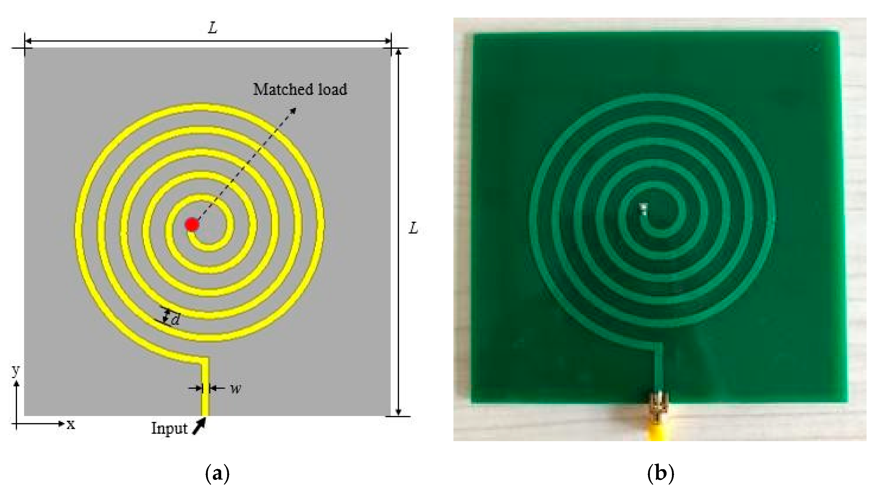
The configuration of the proposed antenna is shown in Figure 1. Referring to Figure 1, the antenna consists of a radiation patch with five and a quarter turns of a spiral, an FR4 dielectric substrate with a dielectric constant of 4.4, a loss tangent of 0.02, and a metal ground plate. The dimensions of the metal ground plane are the same as the FR4 dielectric substrate. To ease processing, an extension line was added to the outer ring of the spiral, and side feed mode was used for feeding. A 50 Ω resistor at the end of the spiral wire formed the traveling-wave antenna. The optimized parameters of the proposed antenna are shown in Table 1. Referring to Table 1, L is the perimeter, d is the loop spacing, w is the microstrip line width of the planar helix, and h is the substrate thickness.
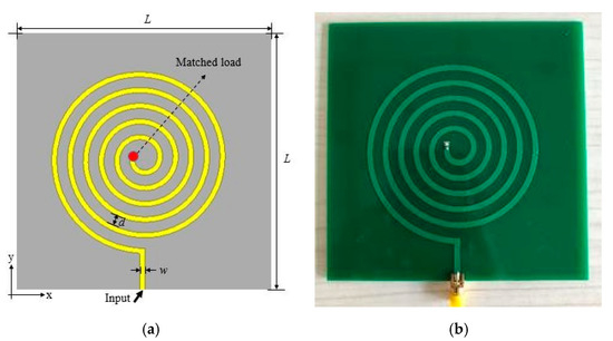
Figure 1.
Configuration of the proposed antenna: (a) schematic and (b) physical representation.

Table 1.
Design parameters of the antenna (unit: mm).
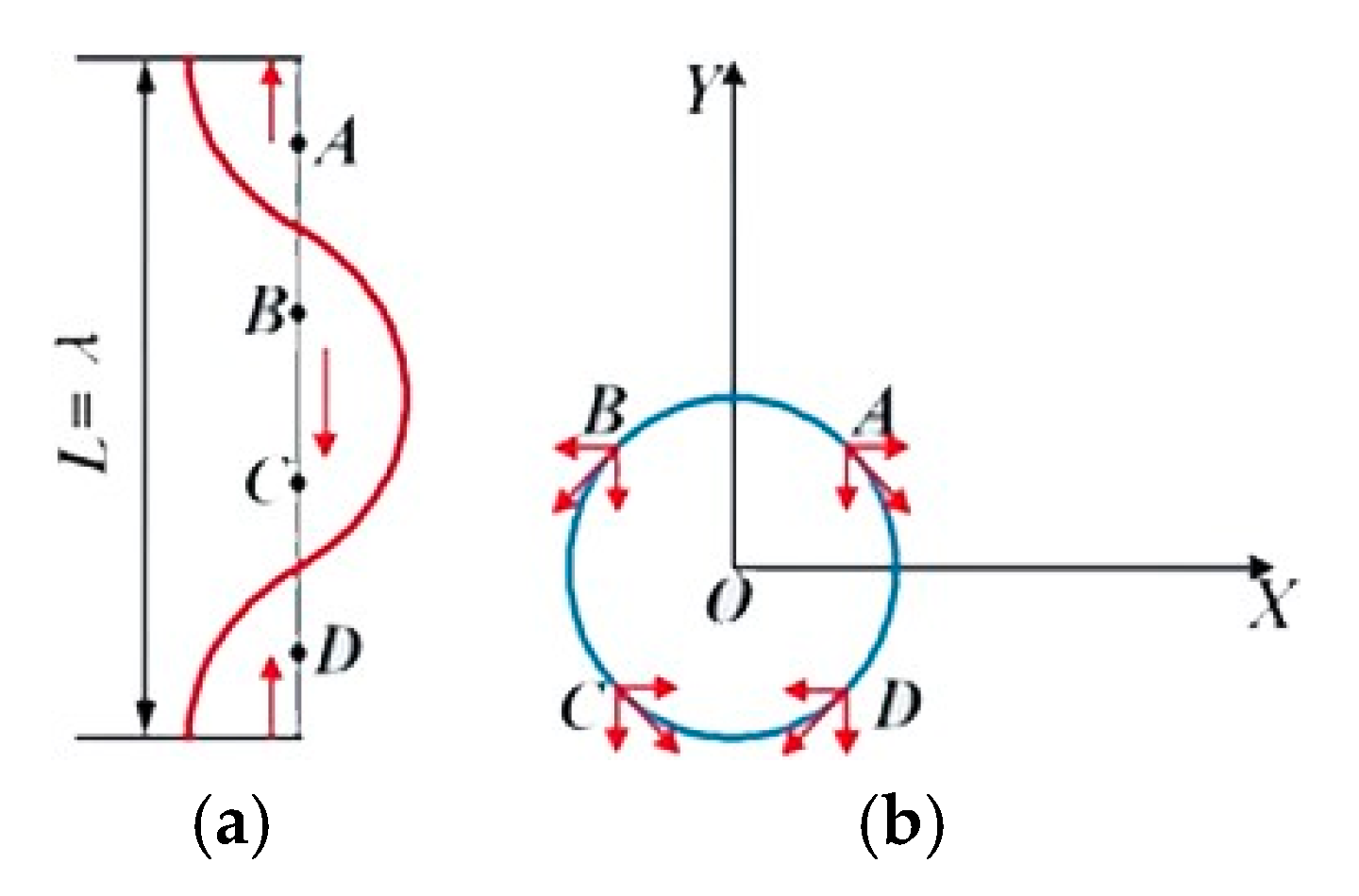
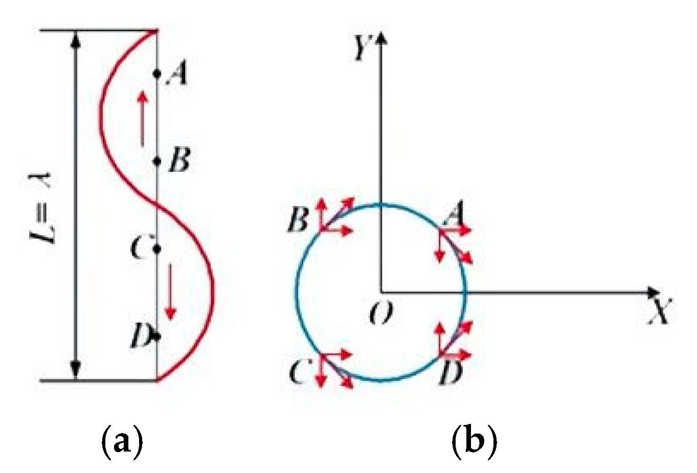
Analysis of the spiral antenna, with perimeter L of one wavelength, revealed that current distribution was different at t = 0 and t = T/4, as shown in Figure 2 and Figure 3, respectively. In Figure 2 and Figure 3A–D are four points distributed along the spiral. The amplitude and direction of current at t = 0 and t = 1/4T (T represents a cycle) are shown in Figure 2a and Figure 3a, respectively. The spiral line projected onto the rings at t = 0 and t = 1/4T is shown in Figure 2b and Figure 3b, respectively. The decomposed currents were superimposed to conclude that the current on the spiral produced a radiated electric field along the −y axis at t = 0 and a radiated electric field in the +x direction at t = T/4. The same analysis revealed that the current on the spiral produced radiated electric fields in the +y and −x directions at t = T/2 and t = 3 × T/4, respectively. As time changes, the current on the spiral produced a continuously rotating, circularly polarized radiation field with angular frequency ω = 2Π/T.
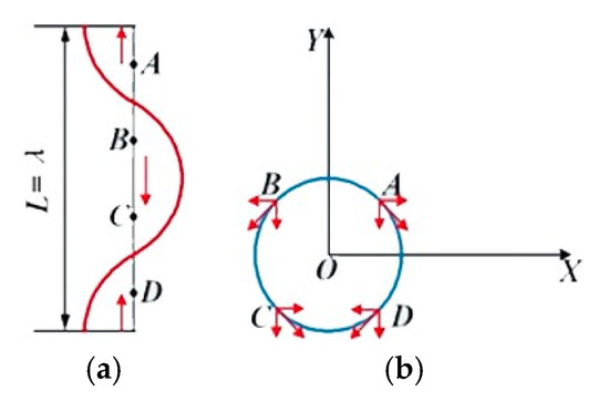
Figure 2.
Current distribution on the spiral at t = 0. (a) the amplitude and direction of current on the unfolding spiral and (b) the amplitude and direction of current on circle spiral.
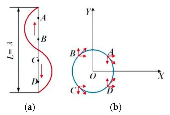
Figure 3.
Current distribution on the spiral at t = T/4. (a) the amplitude and direction of current on the unfolding spiral and (b) the amplitude and direction of current on circle spiral.
The directions of rotation and traveling wave current transmission were consistent on the spiral.
Compared with standing-wave antennas, traveling-wave antennas have better impedance characteristics and a wider impedance bandwidth. There are generally two methods for obtaining traveling waves. The first method involves matching the load at the antenna terminal. The second method involves using the effect of radiation to make the current distributed on the antenna decay continuously when it is radiated. HFSS15 was used as a simulation tool in this study.
2.2. The Measurement of Near-Field RFID Reader Antennas
The electronic field distribution of the near-field antenna is relatively complex. In addition to the reference parameters of the traditional antenna, the polarization direction of the electric-coupled RFID reader antenna and the tag antenna should be considered. The far-field axial ratio is not suitable for describing the polarization of the near-field antenna, so the tag reading rate and reading/writing area are also performance indicators to be considered.
2.2.1. The Reading Rate of Tags
The real reading performance of an RFID reader antenna must be obtained through actual tests. This measurement index is the reading rate of the tags. Based on the reading rate of tags, which is
Reading rate of tags = Number of tags that antenna detected/Total tags.
2.2.2. The Reading/Writing Uniform Area
The reading/writing uniform area of an RFID antenna refers to the area that the antenna can read and write 100%, and the reading/writing area of the antenna affects the application scene of the antenna. A good RFID reader antenna should be able to control its read–write range strictly according to the requirements and achieve strict regional control. The antenna proposed in this paper requires the electric field distribution along x-axis and the y-axis can be controlled.
3. Results
Simulations and measurements were used to evaluate the working performance of the antenna, considering the reflection coefficient, the far-field gain, the radiation efficiency, the reading area of several measurement indicators, and the distribution of electric field components in the space above the antenna and parallel to its surface. The performance of the antenna was evaluated under the assumption that it is placed in the XOY plane. The electric field parallel to the x-axis (Ex) and that parallel to the y-axis (Ey), Ex and Ey, were used, respectively, and these variables were measured in v/m. All distribution maps of electric field components were obtained on the same scale.
3.1. Reflection Coefficient
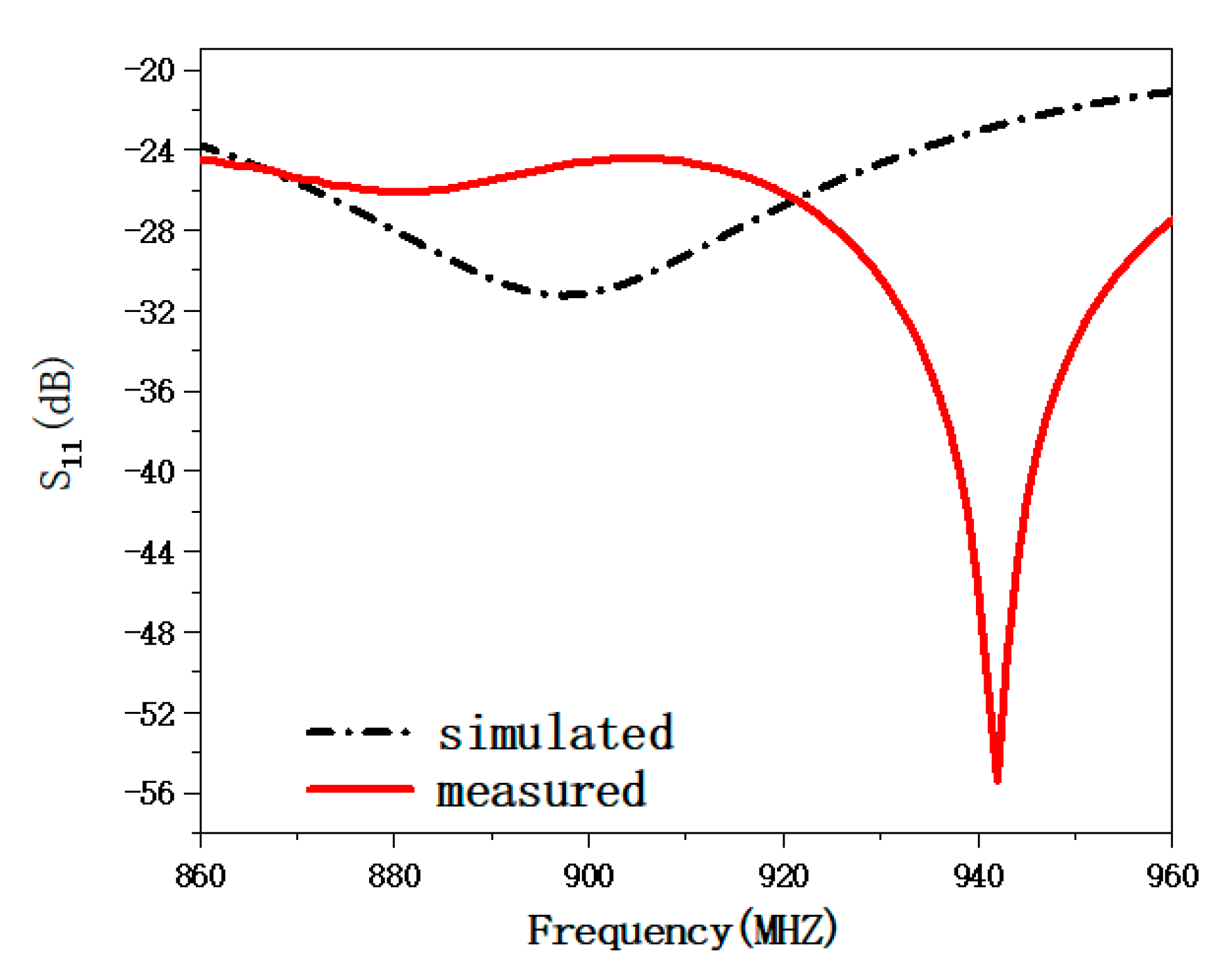
The reflection coefficients of the antenna obtained through simulation and measurements are shown in Figure 4. Referring to Figure 4, it is seen that the proposed spiral traveling-wave antenna has broadband characteristics, and both simulated and real-world reflection coefficients, S11, are less than −10 dB within the frequency range of 860–960 MHz. These properties represent a significant advantage of traveling-wave antennas.
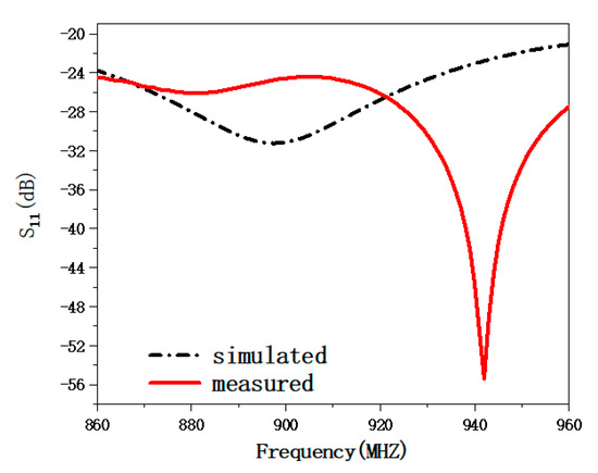
Figure 4.
Reflection coefficients of the spiral antenna obtained through simulation and real-world measurements.
3.2. Far-Field Gain and Reading Efficiency
Unlike reader antennas for far-field RFID applications, reader antennas for near-field RFID applications require low gain in order to avoid the misreading of tags outside the reading area and achieve a controllable reading distance.
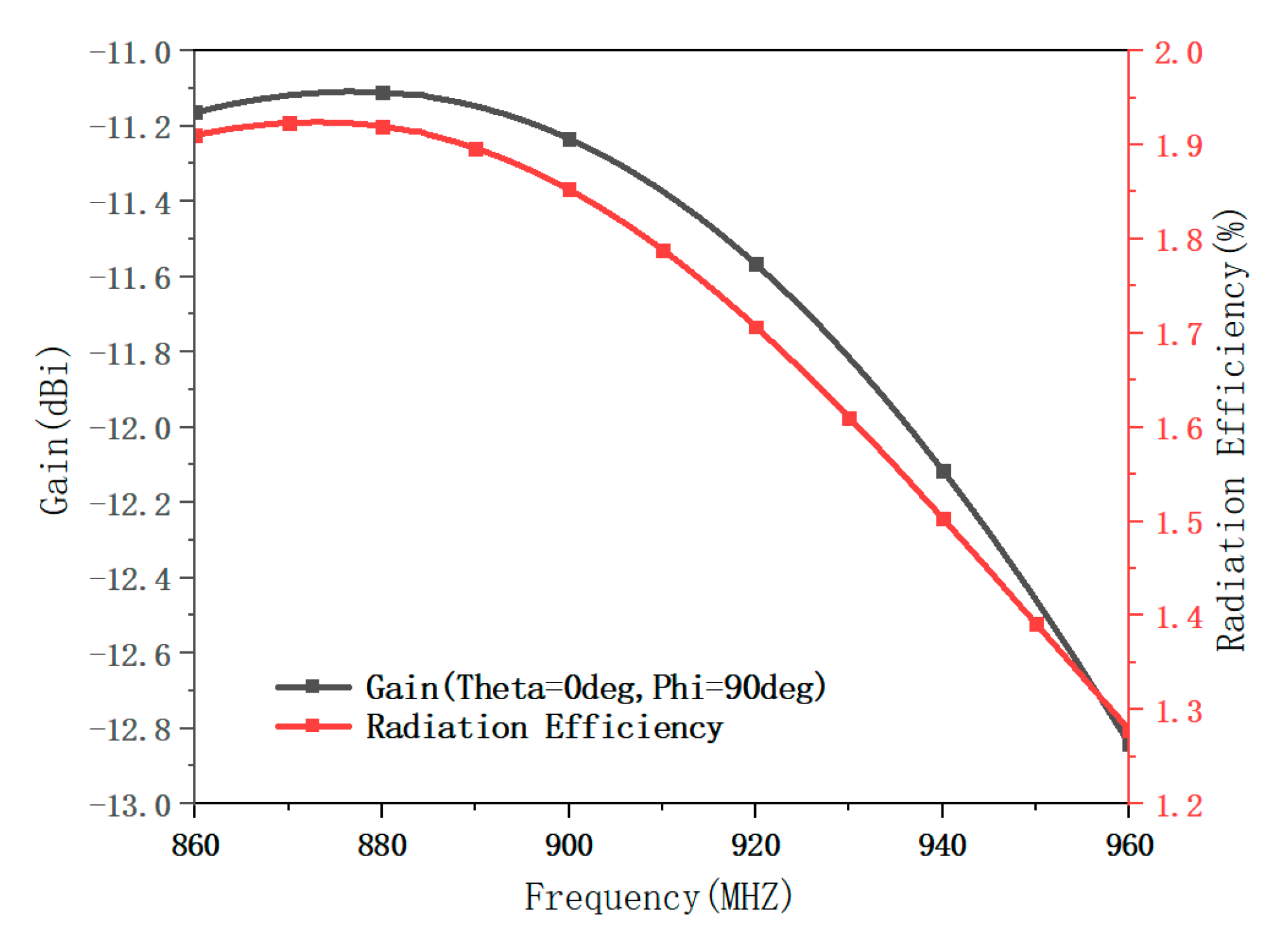
Figure 5 presents a graph of gain in the simulated spiral antenna (antenna in Figure 1a) and the radiation efficiency as a function of frequency. The antenna consists of a radiation patch with five and a quarter turns of the spiral, an FR4 dielectric substrate with a dielectric constant of 4.4, a loss tangent of 0.02, and a metal ground plate. The dimension of the metal ground is the same as the FR4 dielectric substrate, and the thickness of the substrate is 1.6 mm.

Figure 5.
Simulated far-field gain and radiation efficiency of the spiral antenna.
Referring to Figure 5, gain in the proposed spiral antenna is less than −11 dBi, and the radiation efficiency does not exceed 0.02. After being fed from the feed port, the energy in the antenna is continuously attenuated along the spiral, and most of the energy is oscillated and lost in the substrate. The introduction of a ground plate cancels the strength of the far field under the influence of a mirror source; hence, the far-field gain is lower, and the distance of electromagnetic wave propagation ius short. The far-field gain and radiation efficiency are references that confirm the near-field operation of the antenna from the side.
3.3. Electric Field Distribution
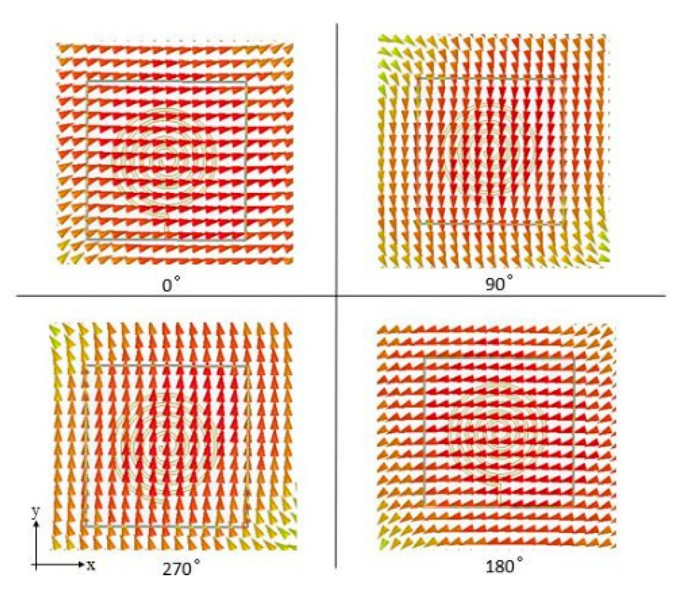
The distribution of the electromagnetic field is the most important performance index of reader antennas for RFID near-field applications. The distribution of the electric field in the antenna was described in terms of the direction of the electric field and the distribution of electric field components along the x- and y-axes. Figure 6 shows the simulation of the electric field direction in one cycle, parallel to the antenna surface and 100 mm from the antenna, at phases 0°, 90°, 180°, and 270°. Referring to Figure 6, the direction of the electric field changes with each phase and rotates clockwise as the phase increases from 0° to 270°. This indicates that the antenna is a multi-polarized antenna and that the direction of rotation of the polarization is consistent with the current along the spiral. This antenna could, therefore, read linearly polarized tags placed parallel to it in the reading area.
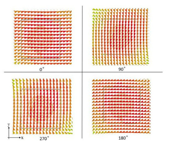
Figure 6.
Simulation of electric field direction, parallel to the antenna surface and 100 mm from the antenna, at phases 0°, 90°, 180°, and 270°.
Figure 7 and Figure 8 show simulations of the distribution of electric field components Ex and Ey in the proposed antenna at different heights. Figure 7 and Figure 8 demonstrate that the reading area is controllable and that the distribution of electric field components in the proposed antenna is uniform along both x- and y-axes. The coverage areas of Ex and Ey are dependent on the structure of the antenna. At any given height, electric fields are strongest at locations directly opposite to the center of the antenna at any given height. Additionally, the strength of the electric fields reduces across locations farther from the center of the antenna. Referring to Figure 7 and Figure 8, the strength and coverage area of electric field components decrease as the distance from the antenna surface increases. There are no zero points in the reading area of the antenna, which satisfies the requirements for RFID near-field applications.
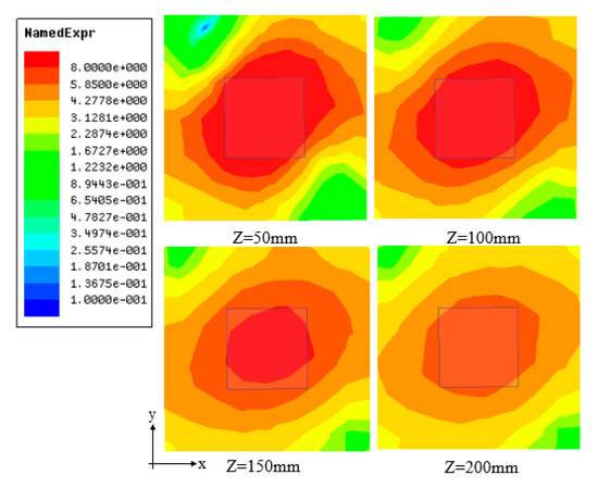
Figure 7.
Simulation of the distribution of the electric field component Ex at different heights.
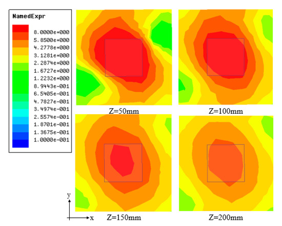
Figure 8.
Simulation of the distribution of the electric field component Ey at different heights.
3.4. Parametric Analysis
This section simulated and analyzed key parameters that affect the planar spiral antenna, the number of spiral loops, and loop spacing.
3.4.1. Number of Spiral Loops
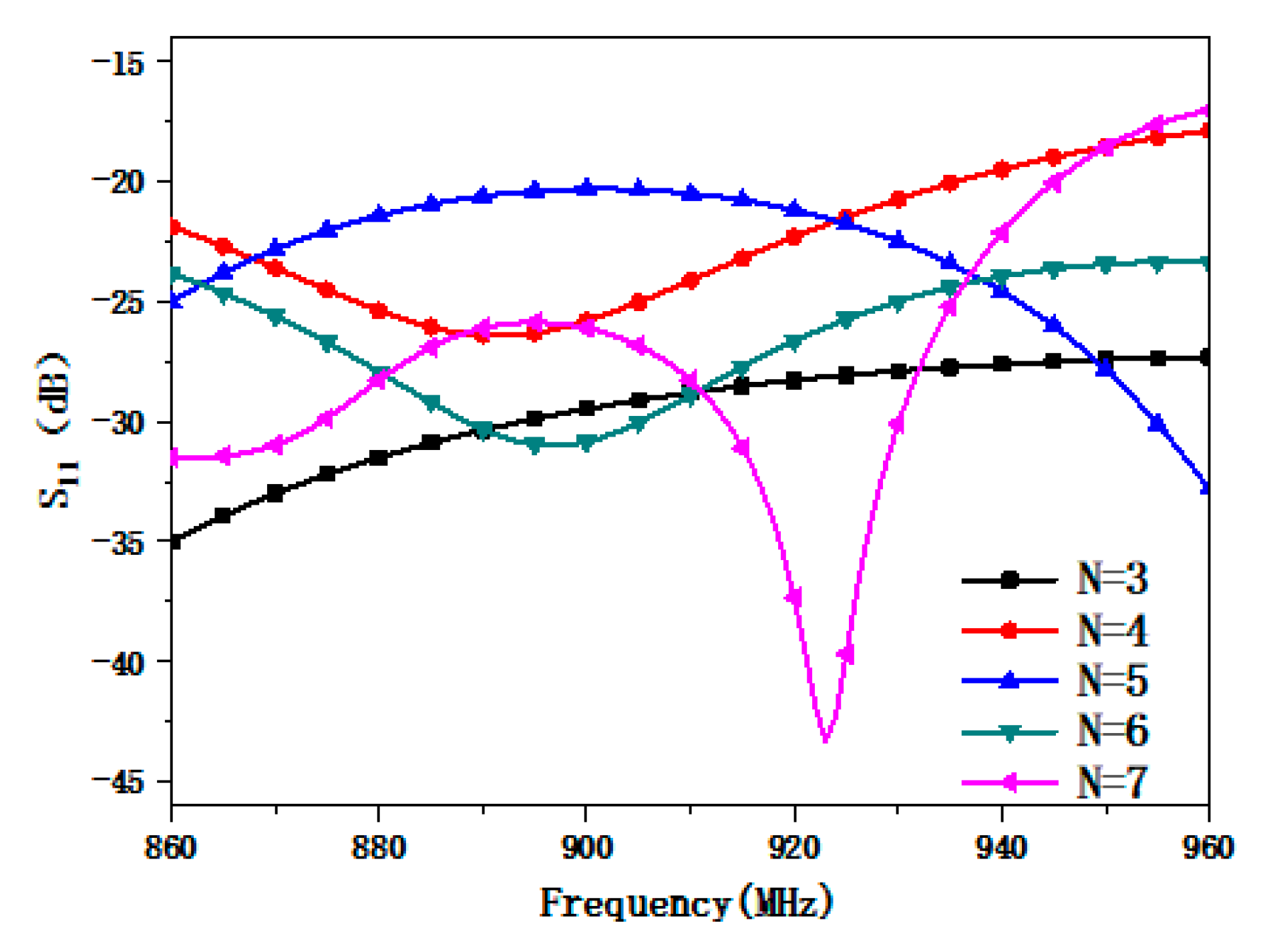
To analyze the impact of the number of spiral loops on antenna performance, the reflection coefficient and distribution of electric field components (Ex, Ey) of the antenna were simulated. The number of spiral loops, N, in the simulation was set to 3, 4, 5, 6, and 7, while other parameters shown in Table 1 were left unchanged.
Figure 9 shows the simulated reflection coefficient S11 with different numbers of spiral loops in the antenna. Changing the number of spiral loops affects the magnitude of the reflection coefficient S11 and the location of the antenna resonance point.
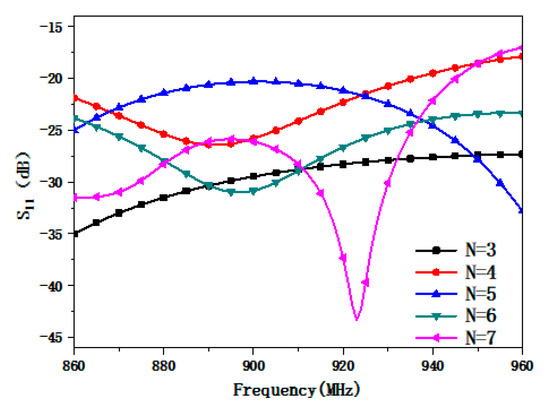
Figure 9.
Simulated reflection coefficient S11 with different numbers of spiral loops in the antenna.
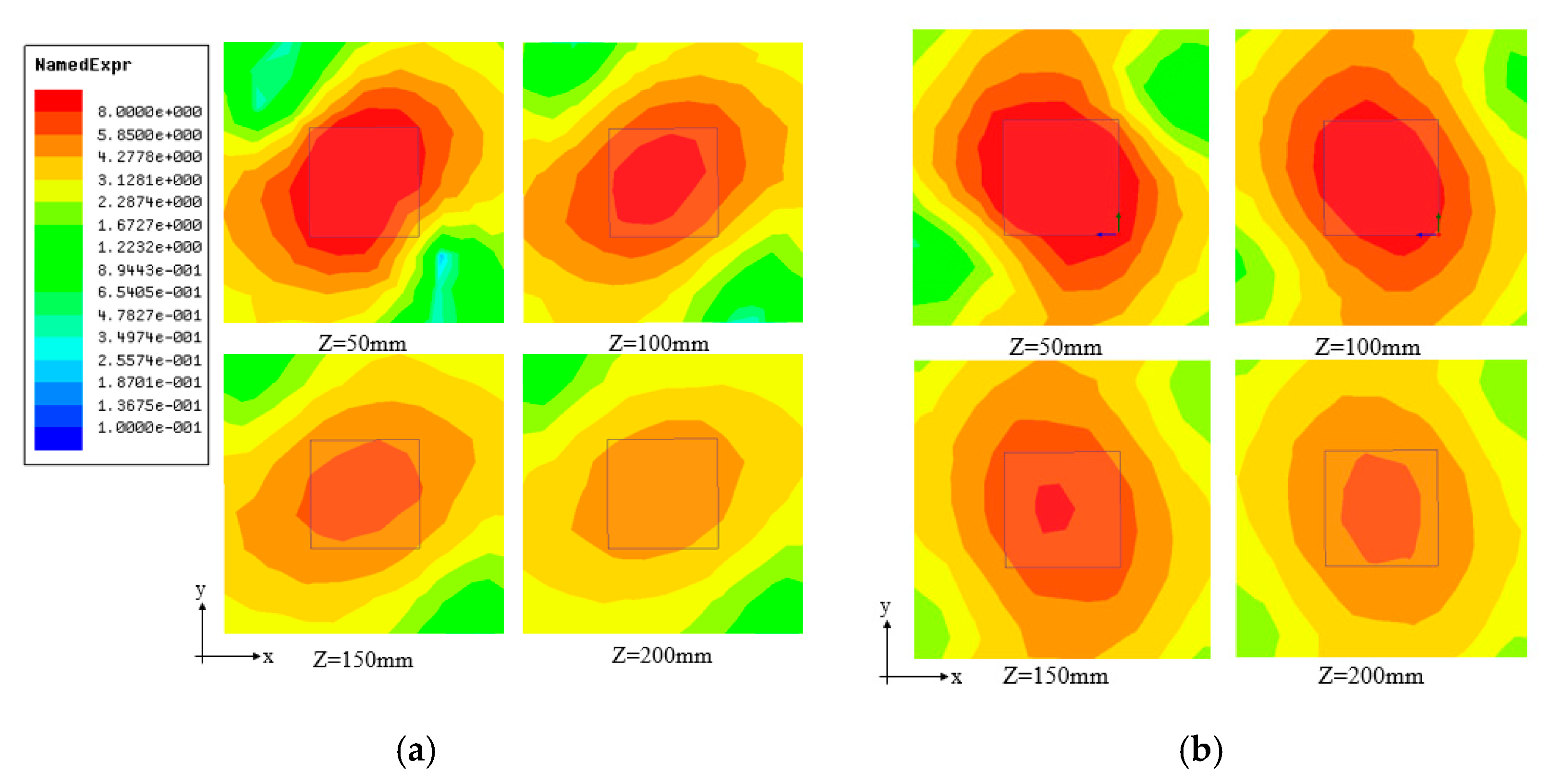
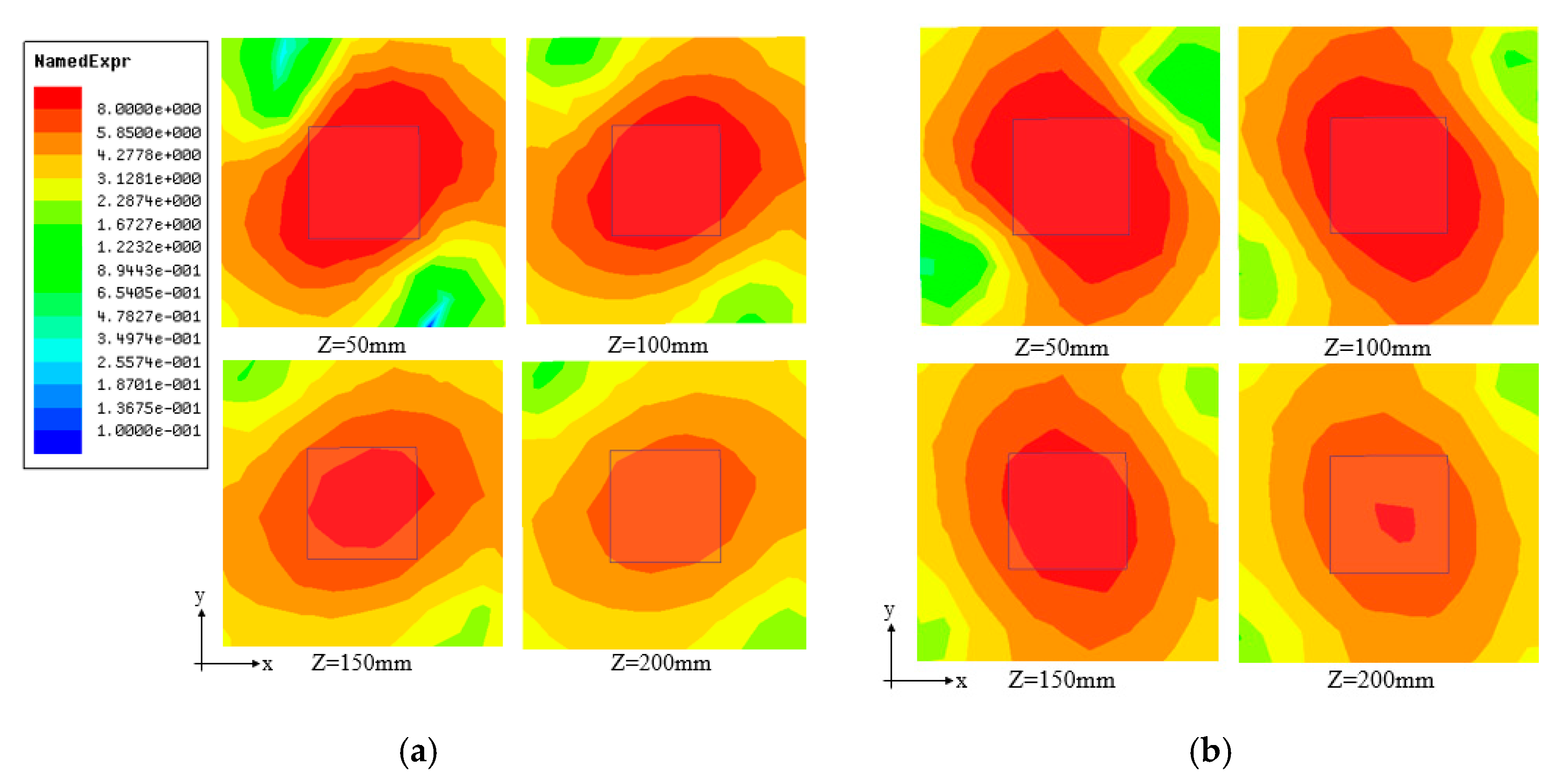
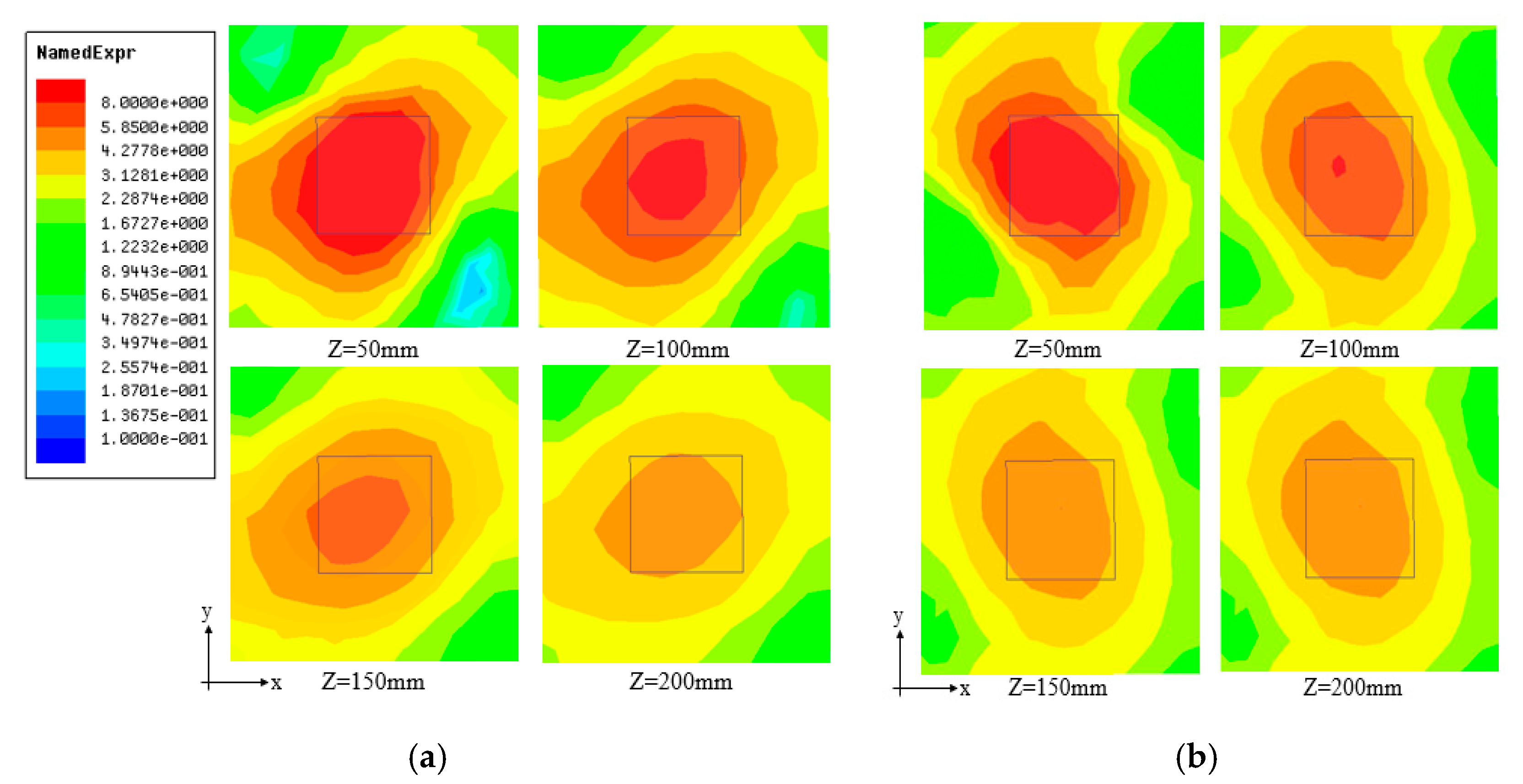
Figure 10, Figure 11, Figure 12, Figure 13 and Figure 14 show the distribution of simulated electric field components (Ex, Ey) at different heights for the antenna with 3–7 spiral loops. Figure 12, Figure 13, Figure 14, Figure 15 and Figure 16 show that the number of spiral loops, N, has a significant effect on the distribution of electric field components parallel to the antenna. When the number of spiral loops, N, is small, the intensity of the electric field components in the horizontal direction increases as the number of spiral loops increases. When the number of spiral loops is large, the intensity of the electric field components in the horizontal direction decreases as the number of spiral loops increases.
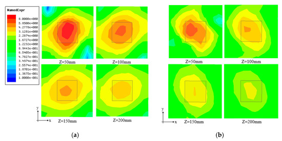
Figure 10.
Distribution of simulated electric field components (Ex, Ey) at different heights with three spiral loops: (a) Ex distribution and (b) Ey distribution.

Figure 11.
Distribution of simulated electric field components (Ex, Ey) at different heights with four spiral loops: (a) Ex distribution and (b) Ey distribution.
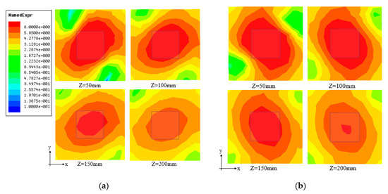
Figure 12.
Distribution of simulated electric field components (Ex, Ey) at different heights with five spiral loops: (a) Ex distribution and (b) Ey distribution.
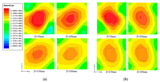
Figure 13.
Distribution of simulated electric field components (Ex, Ey) at different heights with six spiral loops: (a) Ex distribution and (b) Ey distribution.

Figure 14.
Distribution of simulated electric field components (Ex, Ey) at different heights with seven spiral loops: (a) Ex distribution and (b) Ey distribution.
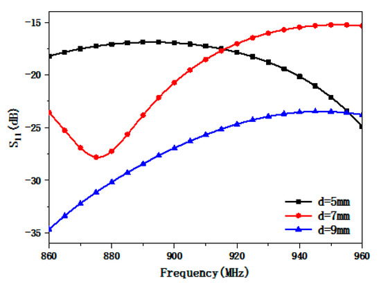
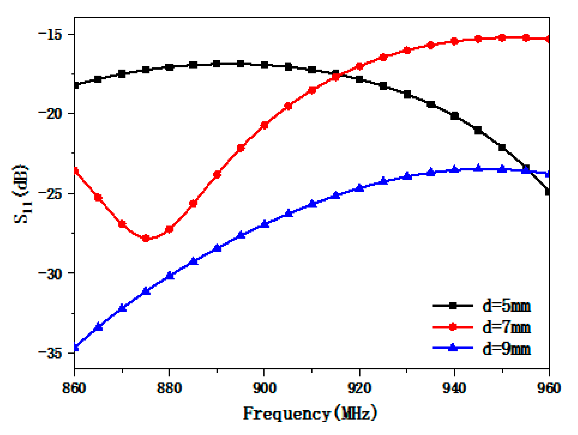
Figure 15.
Simulated reflection coefficient S11 with different loop spacings in the antenna.
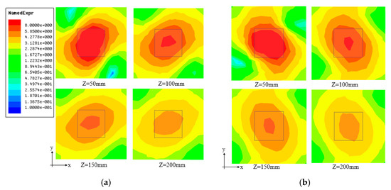
Figure 16.
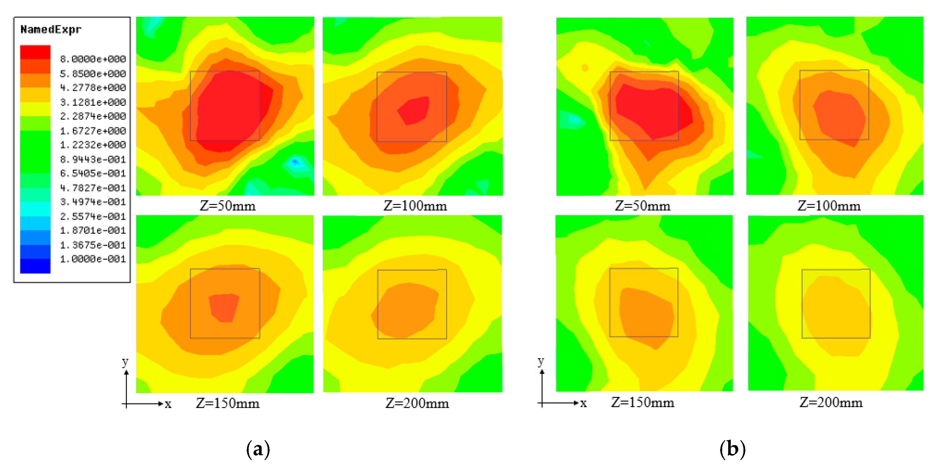
Distribution of simulated electric field components (Ex, Ey) at different heights when loop spacing d = 5 mm: (a) Ex distribution and (b) Ey distribution.
The radiation area is small, and most of the energy is lost due to terminal resistance when the number of spiral loops is smaller than the critical value. Energy is dispersed and the electric field strength is reduced when the number of spiral loops is larger than the critical value. Analyzing Figure 12, Figure 13, Figure 14, Figure 15 and Figure 16 reveals that the critical value is about 5. The horizontal component of the radiated electric field is strongest when the number of spiral loops is about 5.
3.4.2. Loop Spacing
To analyze the impact of loop spacing on the antenna performance, the reflection coefficient and distribution of electric field components (Ex, Ey) of the antenna were simulated. The loop spacing d was set to 5, 7, and 9 mm, while the other parameters in Table 1 were kept unchanged. Figure 15 shows the simulated reflection coefficient S11 with different loop spacings. It is seen in Figure 15 that changing the loop spacing affects the location of the antenna resonance point and the magnitude of the reflection coefficient S11. Referring to Figure 15, the reflection coefficient S11 is less than −10 dB within the simulated frequency band of 860–960 MHz. This meets the requirements of the intended application.
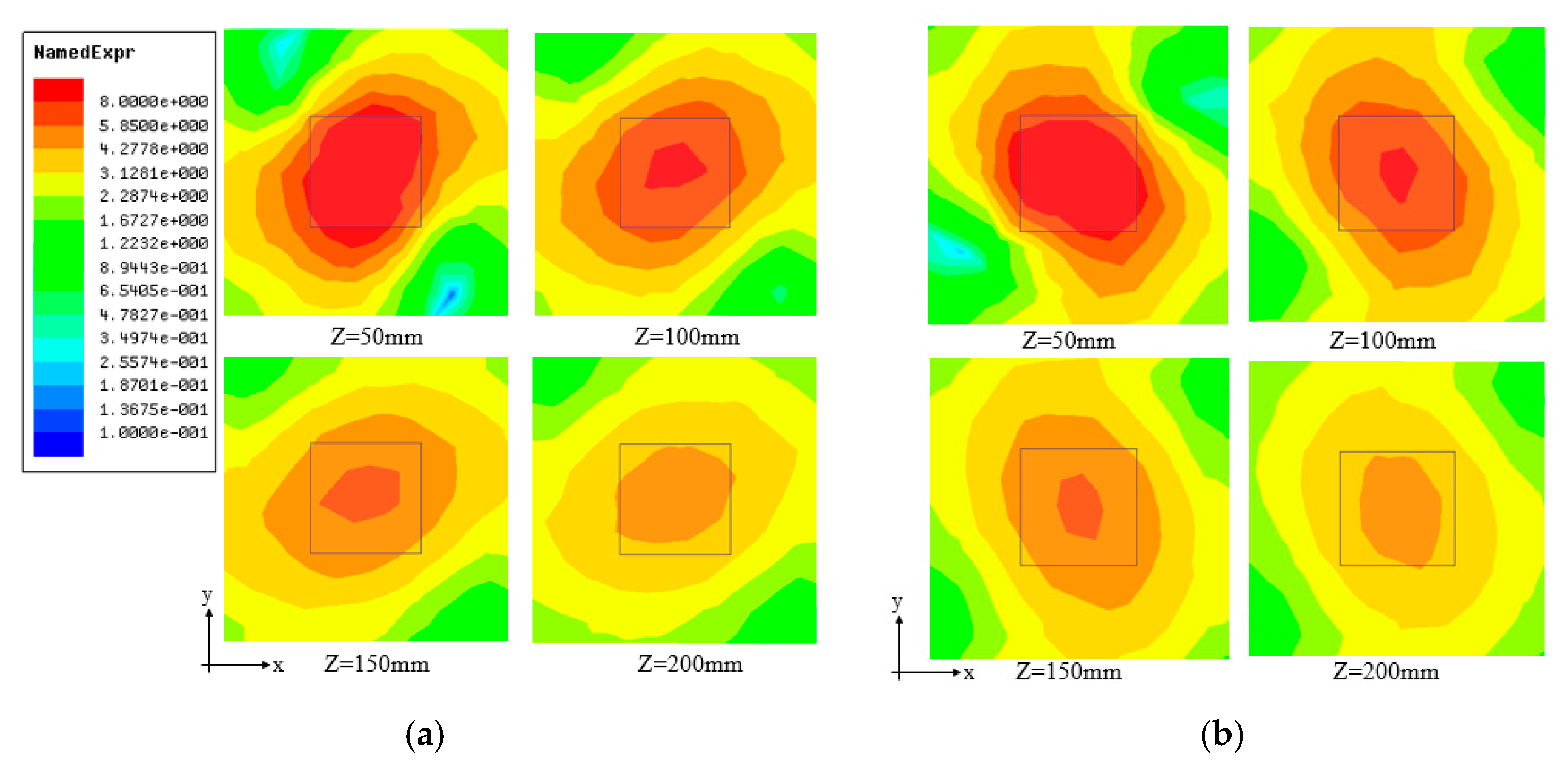
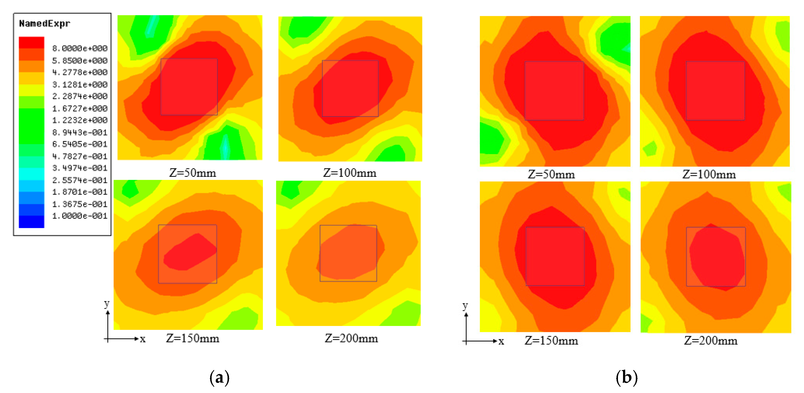
Figure 16, Figure 17 and Figure 18 show the distribution of simulated electric field components (Ex, Ey) of the spiral antenna at different heights when the loop spacing d was 5, 7, and 9 mm, respectively. The effect of loop spacing on the electric field strength is obvious in Figure 16, Figure 17 and Figure 18. Figure 16, Figure 17 and Figure 18 demonstrate that the horizontal component of the electric field is strongest when the loop spacing d is about 7 mm.
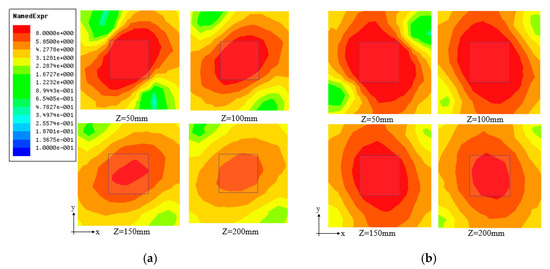
Figure 17.
Distribution of simulated electric field components (Ex, Ey) at different heights when loop spacing d = 7 mm: (a) Ex distribution and (b) Ey distribution.
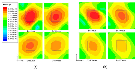
Figure 18.
Distribution of simulated electric field components (Ex, Ey) at different heights when loop spacing d = 9 mm: (a) Ex distribution and (b) Ey distribution.
In summary, the number of spiral loops and loop spacings were demonstrated to have significant effects on electric field components (Ex, Ey). The electric field components (Ex, Ey) were strongest when the number of spiral loops, N, was about 5 and the loop spacing d was about 7 mm. The optimal values of spiral loops N and loop spacing d were 5.25 and 7.5 mm, respectively. These optimized values were used as the parameters of the antenna proposed in this paper.
3.4.3. Antenna Unit
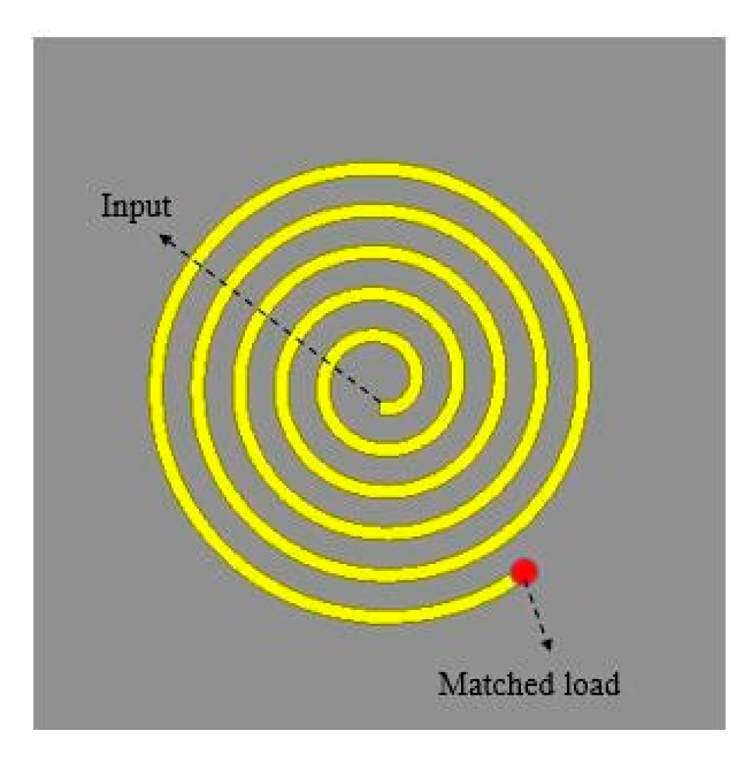
The structure shown in Figure 19 is used as the antenna unit in the array in order to expand the reading area to make the antenna suitable for different applications. Comparing the antenna in Figure 1 and Figure 19, the electric field intensity and uniform area of the simulated were approximately the same. Thus, we use coaxial feed at the center of the spiral loop to facilitate array design. The antenna unit was obtained by removing the extension line and changing the position of the feed port to the center of the spiral according to the structure shown in Figure 1. Except the number of spiral loops, N, the parameters of the real-world antenna unit in Figure 1 were consistent with those of the simulated antenna unit in Figure 20. The number of spiral loops was changed in order to adjust the antenna resonance point. The dielectric substrate is made of FR4 with a dielectric constant of 4.4. The size of the ground is 126 mm × 126 mm. A matched load with a resistance of 50 Ω was connected to the end of the spiral in order to form a traveling-wave antenna.

Figure 19.
Structure of the array antenna unit.
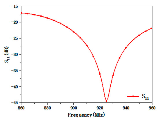
Figure 20.
Simulated reflection coefficients S11 of the antenna unit.
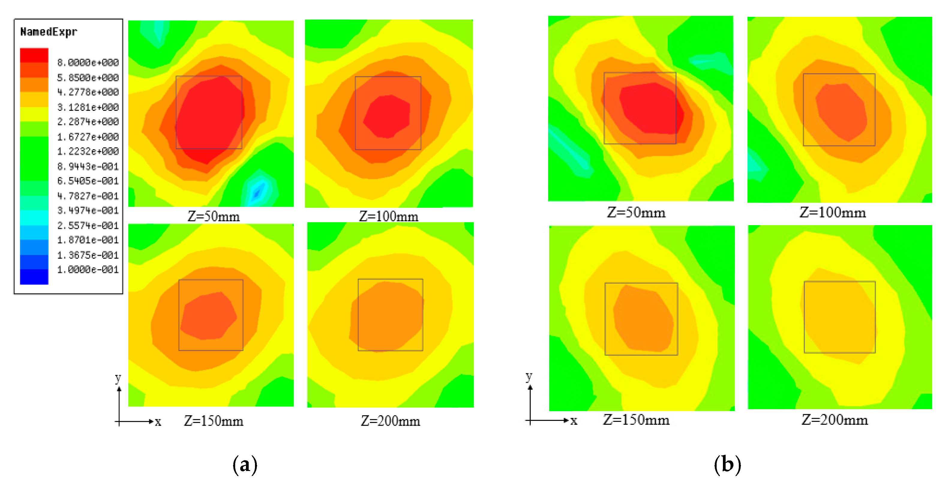
Figure 21 shows the distribution of electric field components (Ex, Ey) of the antenna unit at different heights. The direction of polarization of the antenna unit is different from that of the proposed spiral antenna because the position of the antenna feed port and the direction of current rotation both change. The coverage areas of the electric field components (Ex, Ey) of the antenna unit are also inconsistent with those of the proposed spiral antenna. The distribution of electric field components in the x- and y-directions of the antenna unit is uniform, and the reading area is controllable. There are no zero points in the reading area. The antenna can be used as an RFID reader antenna in near-field applications.
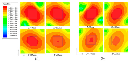
Figure 21.
Simulated distribution of electric field components (Ex, Ey) of the antenna unit at different heights: (a) Ex distribution and (b) Ey distribution.
3.4.4. Array
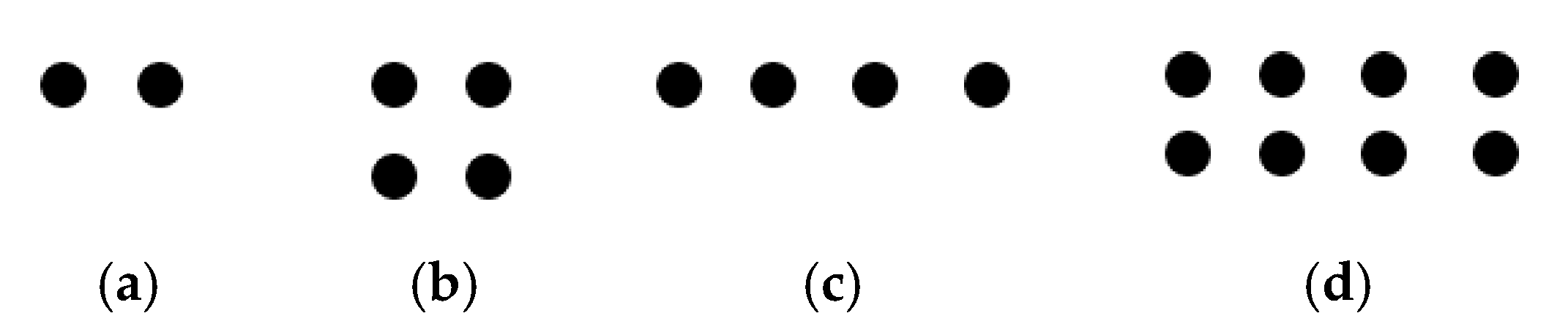
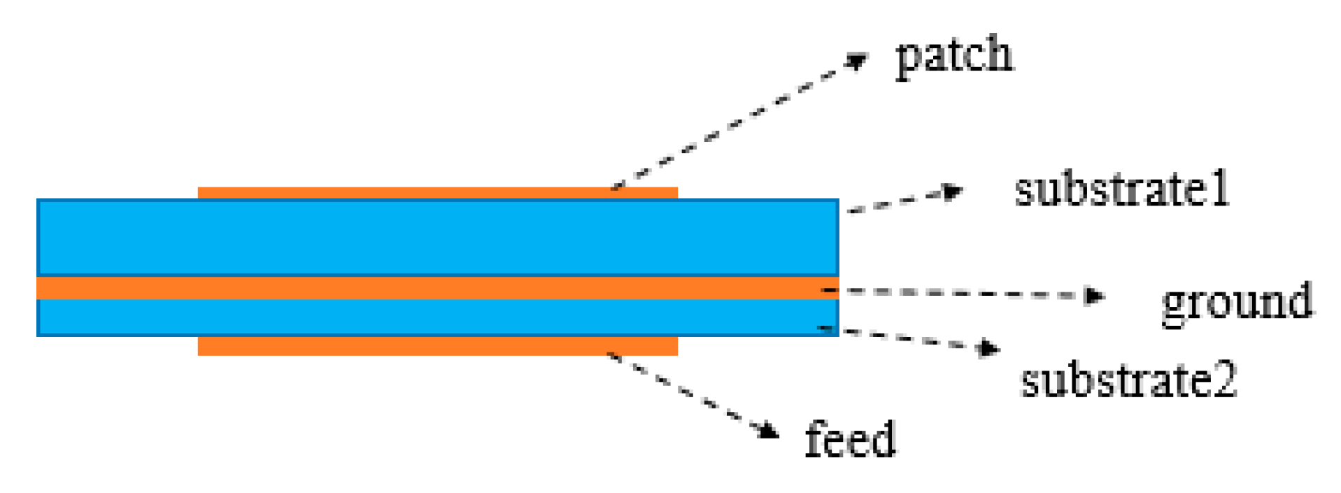
To verify the scalability of the reading area of the spiral antenna unit, it was used for array design, and simulations were conducted using 1 × 2, 2 × 2, 1 × 4, and 2 × 4 arrays. The distribution of antenna units in the array is shown in Figure 22, and the side view of the array antenna is shown in Figure 23. Array antennas consisted of a radiating patch, an FR4 dielectric substrate with a thickness of 1.5 mm, a metal ground plate, an FR4 dielectric substrate with a thickness of 0.6 mm, and a feeding network. The distance between the center of any two adjacent antenna units was 126 mm. The feeding network adopted the form of one is divided into two, one is divided into four, one is divided into four, one is divided into eight. In addition, side feed mode was used for feeding.

Figure 22.
Distribution of antenna units in the array: (a) 1 × 2, (b) 2 × 2, (c) 1 × 4, and (d) 2 × 4 arrays.
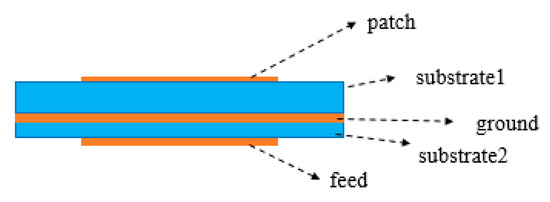
Figure 23.
Side view of the array antenna.
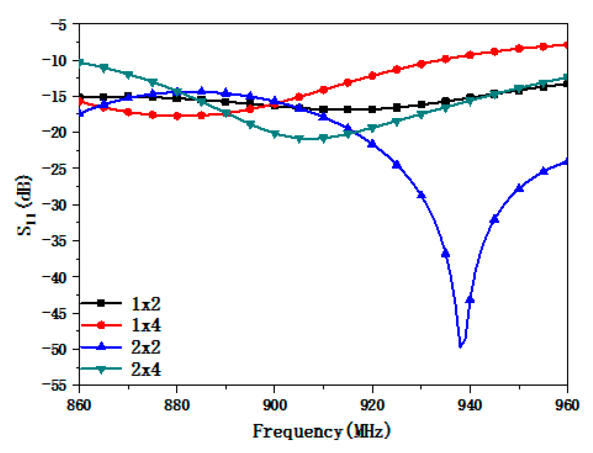
The reflection coefficient and horizontal electric field component of the array antenna were simulated in order to analyze its performance. Figure 24 shows the simulated reflection coefficients of the array antenna with different arrays. Referring to Figure 24, the 1 × 2, 1 × 4, and 2 × 4 arrays achieve good impedance matching in the simulated 860–960 MHz frequency band. Additionally, the impedance bandwidth of the 2 × 2 array antenna is 860–933 MHz. The impedance characteristics of the array antenna are somewhat different from those of the antenna unit due to the presence of the matching network and the difference in the array antenna’s effective working area. The array antenna, however, meets the requirement for the desired application.

Figure 24.
Simulated reflection coefficients of the array antenna.
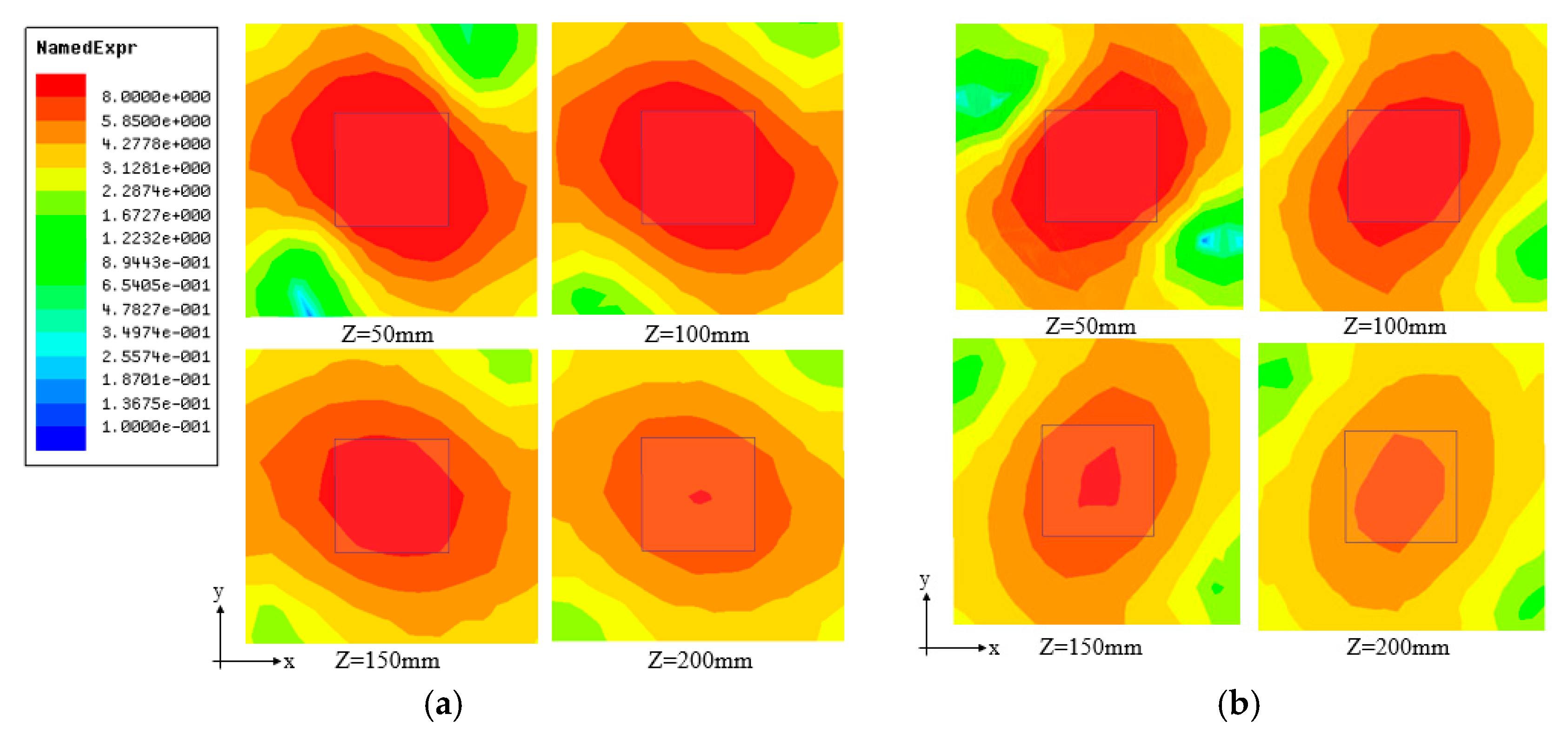
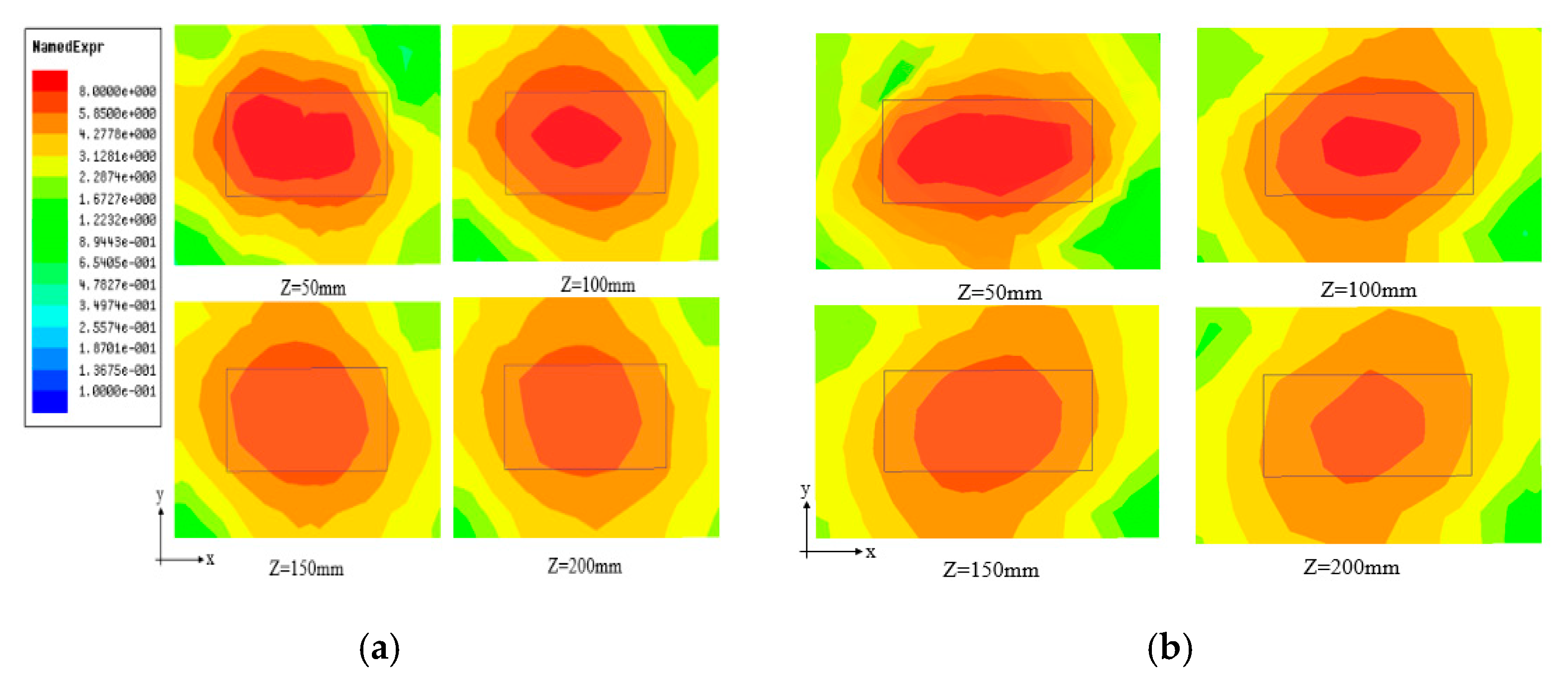
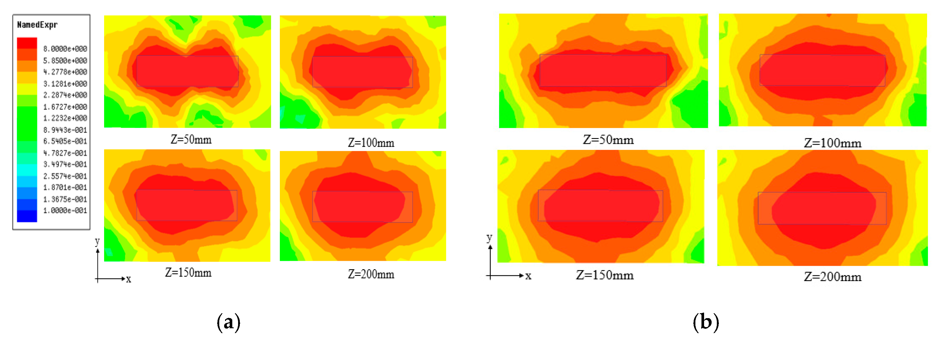
Figure 25, Figure 26, Figure 27 and Figure 28 show the simulated distribution of electric field components (Ex, Ey) at different heights for 1 × 2, 2 × 2, 1 × 4, and 2 × 4 array antennas, respectively. Figure 25, Figure 26, Figure 27 and Figure 28 show that the number of antenna units affects the electric field strength; hence, there is a trade-off between the electric field strength (reading height) and the horizontal reading area during design. The distribution of electric field components excited by the array antennas is uniform in the x- and y-directions, and the reading area is controllable. There is no zero point in the reading area, which meets the requirement for use as a reader antenna in RFID near-field applications. The proposed spiral antenna has an expandable reading area, which makes it suitable for different applications by changing the number of array units.
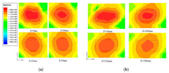
Figure 25.
Simulated distribution of electric field components (Ex, Ey) at different heights for a 1 × 2 array antenna: (a) Ex distribution and (b) Ey distribution.
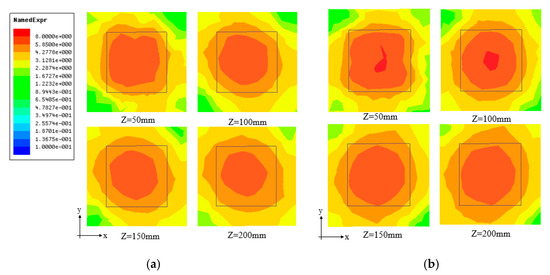
Figure 26.
Simulated distribution of electric field components (Ex, Ey) at different heights for a 2 × 2 array antenna: (a) Ex distribution and (b) Ey distribution.

Figure 27.
Simulated distribution of electric field components (Ex, Ey) at different heights for a 1 × 4 array antenna: (a) Ex distribution and (b) Ey distribution.
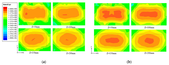
Figure 28.
Simulated distribution of electric field components (Ex, Ey) at different heights for a 2 × 4 array antenna: (a) Ex distribution and (b) Ey distribution.
4. Discussion
4.1. The Electric Field Distribution along X-Axis (Ex) and Y-Axis (Ey)
The traditional RFID reader antenna can realize uniform distribution of the electric field in the horizontal direction, ignoring the diversity of the orientation of the tags. If the distribution of the electric field in a single direction is non-uniform, it will cause missed reading of the tags. The RFID reader antenna can be divided into a circularly polarized antenna [23], a multipolar antenna [24], a traveling-wave antenna [26], a standing-wave antenna [27], etc. The antennas all focus on the horizontal synthetic electric field and achieve the synthetic electric field uniform. However, the electronic field distribution in single direction is non-uniform, such as the electronic field distribution along the x-axis (Ex) and y-axis (Ey), which can cause the misread of RFID tags and influence the accuracy of data reading. Therefore, it is important to achieve uniform distribution of electric fields Ex and Ey. The antenna proposed in this paper can achieve Ex and Ey distribution uniform, and the simulation results are good. The proposed antenna’s results compared with other antennas are shown in Table 2.
Table 2.
Comparison with other antennas.
4.2. Reading Area
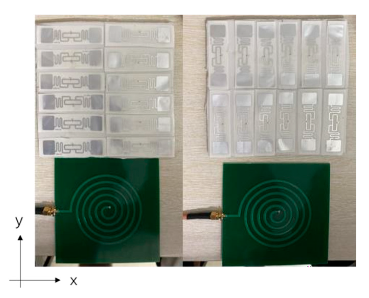
To measure the reading area of the antenna for tags parallel to the x- and y-axes, the antenna was used as an RFID reader in an open test system, as shown in Figure 29. The tag adopts the Alien A9662 dipole with dimensions of 70 mm × 17 mm. The antenna was directly connected to an Impinj Speedway R420 reader through a low-loss coaxial line, and the reader operating frequency was set to 920–925 MHz with an output power of 30 dBm. A hard 150 mm × 150 mm thin plastic foam board was placed directly above the antenna and divided into 12 even parts, each of which was square with dimensions 70 mm × 17 mm. The reading rate of the tag is illustrated in Figure 14. Referring to Figure 30, the antenna achieved a 100% reading rate of tags placed along the x- and y-axes of antenna at distances of 0–220 mm from the antenna surface. The reading area had dimensions of 150 mm × 150 mm × 220 mm. In the area close to the antenna, the electric field intensity was large, and the electric field range was wide. The reading range and electric field intensity both decreased with increasing distance between the tag and the antenna surface.

Figure 29.
Test system for measuring the reading area of the proposed antenna.
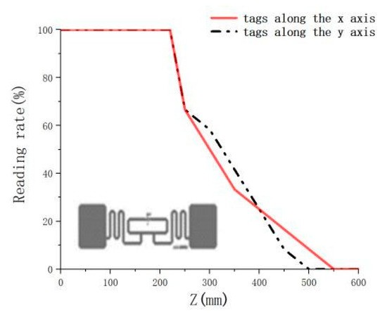
Figure 30.
Reading rate of the tag along the x-axis and y-axis of the antenna at different distances from the antenna.
5. Conclusions
This paper proposed a novel antenna, with uniform horizontal electric field distribution and multi-polarization, for UHF RFID near-field applications. The proposed antenna has a wide frequency band and low gain. The horizontal electric field component excited by the antenna is uniformly distributed, and the reading area is controllable. There are no zero points, which makes the proposed antenna suitable as a reader antenna in RFID near-field applications. The impact of certain parameters on the performance of the proposed spiral antenna was analyzed. To verify the scalability of the reading area of the spiral antenna, 1 × 2, 2 × 2, 1 × 4, and 2 × 4 array antennas were simulated with the proposed spiral antenna.
Author Contributions
Conceptualization, Y.Y.; methodology, Y.Y.; software, Q.G.; validation, Y.Y., Q.G., J.Y. and X.C.; formal analysis, Q.G.; investigation, Q.G. and Y.Y.; resources, Y.Y.; data curation, Q.G.; writing—original draft preparation, Q.G.; writing—review and editing, Y.Y., J.Y. and X.C.; visualization, Q.G., Y.Y., J.Y. and X.C.; supervision, Y.Y.; project administration, Y.Y.; funding acquisition, Y.Y. All authors have read and agreed to the published version of the manuscript.
Funding
This research received no external funding.
Conflicts of Interest
The authors declare no conflict of interest.
References
- Dobkin, M.; Weigand, S.M.; Iyer, N. Segmented magnetic antennas for near- field UHF RFID. Microw. J. 2007, 50, 96–102. [Google Scholar]
- Qing, X.; Chen, Z.; Goh, C. UHF near-field RFID reader antenna with capacitive couplers. Electron. Lett. 2010, 46, 1591. [Google Scholar] [CrossRef]
- Ong, Y.S.; Qing, X.; Goh, C.K.; Chen, Z.N. A Segmented loop antenna for UHF near-field RFID. In Proceedings of the 2010 IEEE Antennas and Propagation Society International Symposium, Toronto, ON, Canada, 11–17 July 2010. [Google Scholar]
- Chen, Z.N.; Goh, C.K.; Qing, X. Loop antenna for UHF near-field RFID reader. In Proceedings of the Fourth European Conference on Antennas and Propagation, Barcelona, Spain, 1–4 April 2010. [Google Scholar]
- Qing, X.; Goh, C.K.; Chen, Z.N. A Broadband UHF Near-Field RFID Antenna. IEEE Trans. Antennas Propag. 2010, 58, 3829–3838. [Google Scholar] [CrossRef]
- Shi, J.; Qing, X.; Chen, Z.N.; Goh, C.K. Electrically Large Dual-Loop Antenna for UHF Near-Field RFID Reader. IEEE Trans. Antennas Propag. 2013, 61, 1019–1025. [Google Scholar] [CrossRef]
- Shi, J.; Qing, X.; Chen, Z.N. Electrically Large Zero-Phase-Shift Line Grid-Array UHF Near-Field RFID Reader Antenna. IEEE Trans. Antennas Propag. 2014, 62, 2201–2208. [Google Scholar] [CrossRef]
- Zeng, Y.; Chen, Z.N.; Qing, X.; Jin, J.M. Design of a Near-field Nonperiodic Zero Phase Shift-Line Loop Antenna with a Full Dispersion Characterization. IEEE Trans. Antennas Propag. 2017, 65, 2666–2670. [Google Scholar] [CrossRef]
- Zeng, Y.; Chen, Z.N.; Qing, X.; Jin, J.-M. A Directional, Closely Spaced Zero-Phase-Shift-Line Loop Array for UHF Near-Field RFID Reader Antennas. IEEE Trans. Antennas Propag. 2018, 66, 5639–5642. [Google Scholar] [CrossRef]
- Zeng, Y.; Chen, Z.N.; Qing, X.; Jin, J.-M. An Artificial Magnetic Conductor Backed Electrically Large Zero-Phase-Shift Line Grid-Loop Near-Field Antenna. IEEE Trans. Antennas Propag. 2017, 65, 1599–1606. [Google Scholar] [CrossRef]
- Yao, Y.; Liang, Y.; Yu, J.; Chen, X. A Broadband Near-Field UHF RFID Reader Antenna with Low Far-Field Gain. IEEE Trans. Antennas Propag. 2017, 65, 4869–4874. [Google Scholar] [CrossRef]
- Liang, Y.; Yao, Y.; Yu, J.; Chen, X. Design of A Novel Meander Line Reader Antenna for UHF Near-field RFID. In Proceedings of the 2016 11th International Symposium on Antennas, Propagation and EM Theory (ISAPE), Guilin, China, 18–21 October 2016. [Google Scholar]
- Li, X.; Li, Q.; Zhu, H.; Li, Q.; Qi, Z.; Xiao, J. A Novel Near-Field UHF RFID Reader Array Antenna for Configurable Electrically Large Reading Area. IEEE Trans. Antennas Propag. 2019, 67, 6714–6722. [Google Scholar] [CrossRef]
- Caso, R.; Michel, A.; Buffi, A.; Nepa, P.; Isola, G. A modular antenna for UHF RFID near-field desktop reader. In Proceedings of the 2014 IEEE RFID Technology and Applications Conference (RFID-TA), Tampere, Finland, 8–9 September 2014. [Google Scholar]
- Michel, A.; Buffi, A.; Caso, R.; Nepa, P. A scalable modular antenna configuration to extend the detection volume of a near-field UHF-RFID desktop reader. In Proceedings of the 2015 IEEE International Symposium on Antennas and Propagation & USNC/URSI National Radio Science Meeting, Vancouver, BC, Canada, 19–24 July 2015. [Google Scholar]
- Li, H.; Chen, Y.; Xing, Z.; Yang, S. A Novel Printed Dual-Log- Periodic Array Antenna for UHF Near-Field RFID Applications. IEEE Trans. Antennas Propag. 2018, 66, 7418–7423. [Google Scholar] [CrossRef]
- Jeong, M.-G.; Lee, W.-S. A Smart Blood Bag Management System Using a Load-Integrated U-Shaped Near-Field RFID Antenna Array. IEEE Trans. Antennas Propag. 2019, 67, 1837–1843. [Google Scholar] [CrossRef]
- Huang, C.; Wang, C.; Zhu, J.; Tang, W. Electrically Large Segmented Dipole Array Antenna with Reflectors for UHF Near-Field RFID Applications. IEEE Trans. Antennas Propag. 2019, 67, 4280–4285. [Google Scholar] [CrossRef]
- Medeiros, C.R.; Costa, J.; Fernandes, C.A. RFID Smart Shelf with Confined Detection Volume at UHF. IEEE Antennas Wirel. Propag. Lett. 2008, 7, 773–776. [Google Scholar] [CrossRef]
- Andrenko, A.S.; Kai, M. Novel design of UHF RFID near- field antenna for smart shelf applications. In Proceedings of the 2013 Asia-Pacific Microwave Conference Proceedings (APMC), Seoul, Korea, 5–8 November 2013; pp. 242–244. [Google Scholar]
- Yao, Y.; Cui, C.; Yu, J.; Chen, X. A Meander Line UHF RFID Reader Antenna for Near-field Applications. IEEE Trans. Antennas Propag. 2017, 65, 82–91. [Google Scholar] [CrossRef]
- Andrenko, A.S. Simultaneous Quasi. RHCP and LHCP Radiation in the Near Field of Planar RFID Antennas. In Proceedings of the International Conference on Mathematical Methods in Electromagnetic Theory, Lviv, Ukraine, 18 August 2016. [Google Scholar]
- Wang, M.-S.; Guo, Y.-X.; Wu, W. Planar Shared Antenna Structure for NFC and UHF-RFID Reader Applications. IEEE Trans. Antennas Propag. 2017, 65, 5583–5588. [Google Scholar] [CrossRef]
- Yao, Y.; Liang, Y.; Yu, J.; Chen, X. Design of a Multipolarized RFID Reader Antenna for UHF Near-Field Applications. IEEE Trans. Antennas Propag. 2017, 65, 3344–3351. [Google Scholar] [CrossRef]
- Yao, Y.; Ren, X.; Liang, Y.; Yu, J.; Chen, X. Multipolarized Reader Antenna with Periodic Units Based on Electric Field Coupling for UHF RFID Near-Field Applications. IEEE Trans. Antennas Propag. 2019, 67, 5265–5271. [Google Scholar] [CrossRef]
- Michel, A.; Caso, R.; Buffi, A.; Nepa, P.; Isola, G. An array of meander Travelling Wave Antennas for near-field UHF-RFID readers. In Proceedings of the Antennas & Propagation Society International Symposium, Orlando, FL, USA, 7–13 July 2013. [Google Scholar]
- Guo, J.; Lan, H.; Yin, Y. A Near-Field UHF RFID Reader Antenna without Dead Zones. In Proceedings of the International Conference on Microwave and Millimeter Wave Technology, Chengdu, China, 8–11 May 2018. [Google Scholar]


Publisher’s Note: MDPI stays neutral with regard to jurisdictional claims in published maps and institutional affiliations. |
© 2021 by the authors. Licensee MDPI, Basel, Switzerland. This article is an open access article distributed under the terms and conditions of the Creative Commons Attribution (CC BY) license (https://creativecommons.org/licenses/by/4.0/).