Article

Digital Control of a Stepping Motor for Eliminating Rotation Speed Fluctuations Using Adaptive Gains

1
Department of Intelligent and Mechanical Interaction Systems, University of Tsukuba, Tsukuba 305-8577, Japan
2
National Institude of Technology, Oyama College, Oyama 323-0806, Japan
3
Domain of Mechanical Systems Engineering, Ibaraki University, Hitachi 316-8511, Japan
*
Author to whom correspondence should be addressed.
Electronics 2021, 10(11), 1335; https://doi.org/10.3390/electronics10111335 (registering DOI)
Submission received: 30 April 2021 / Revised: 28 May 2021 / Accepted: 31 May 2021 / Published: 2 June 2021
(This article belongs to the Special Issue Recent Issues on Motors and Motor Drives)

Abstract

:
Nowadays, stepping motors are usually used as precise actuators in various new scientific fields, such as syringe pumps, blood analyzers, and bio-3D printers. Controlling rotation of the stepping motor without speed fluctuation under no-load conditions plays an important role in improving the accuracy of the machine’s drive. This paper proposes a digital control method for a five-phase hybrid stepping motor. The proposed controller includes an original control loop and a PI adaptive integration gain control loop. The original digital control loop is redesigned from the analog controller by using the direct PIM method. The PI adaptive control loop is added to the original control loop in a parallel way to remove a steady deviation of the motor and suppress a physical saturation factor inside the plant. Lyapunov stability theory is used to prove a stability condition of the PI regulator gains. Experimental results show that the proposed controller can suppress the chattering caused by the switching structure and gives performances as good as that of the commercial analog controller in a high rotation speed range without fluctuation.

1. Introduction

A stepping motor is an actuator that can rotate precisely in a feed-forward manner responding to an input pulse signal [1]. As a result, the stepping motor is usually used in precision instrument systems such as syringe pumps, ink-jet bio-printers, and biochemical analyzers. These systems play an important role in high-tech sectors such as micro-fluid, bio-engineering, and laboratory testing and are attracting a great deal of attention in both industry and research [2,3,4,5].
Since the applications of the stepping motor require high accuracy for control of position and speed, a control method that can suppress speed fluctuations of the motor in a high-speed range is an important research topic [6,7]. Li et al. show that each ripple observed at an ultra-low interfacial tension in a syringe pump system is caused by step-wise speed fluctuation of the stepping motor [8]. Zeng et al. show that fluctuation of the stepping motor in the syringe pump generates flow fluctuations, which causes pressure fluctuations in the microfluidic channel [9]. In order to improve the performances of micro-fluid devices, it is necessary to develop a stepping motor system that can suppress the speed fluctuation while controlling the position and speed with high accuracy.
A method, which delays the turn-off instant of the current flowing through the coil winging of one phase before switching to the next phase has been proposed for suppressing the speed fluctuation [10,11]. Another method reverses a phase of excitation damping to generate a torque in an opposite direction and breakes the speed fluctuation before the final stopping position has also been proposed [12,13]. These methods can suppress the speed fluctuations at a low-speed range without using mechanical loads, such as a damper. However, at a high-speed range, these methods may increase the stopping time of the final step. Furthermore, a time of switching and exciting a gate drive can only be determined by trial and error or by qualitative analysis in the phase plane of a model, where the system is approximated to a second-order system. These processes tend to increase the development cost of the system.
An open-loop control using a hysteresis current control method, which is usually implemented by a digital controller with a high sampling frequency, has been proposed to reduce the position errors [14]. An FPGA may be suitable for implementing such a high-sampling frequency digital controller [15]. However, these so-called digital controllers are just an implementation of the conventional analog controllers on a computer. Recently, Yagi et al. proposed a digital current control method for a stepping motor using an adaptive gain tuning [16]. This method allows a control system designer to focus only on the transient response of the plant output to remove the steady-state deviation, without considering the internal model principle [17] for the closed-loop system. This method makes it easier to adjust the transient response during the development process than with conventional analog controllers.
As a result of this study, the stabilization control and constant current control are digitalized and implemented in commercial processors. However, this method may lead to an undesired speed fluctuation characteristic. In order to suppress a windup of the plant input, this method employs an algorithm switching structure based on a threshold value of plant input saturation. This switching causes an oscillatory phenomenon called chattering in the variable gain [18]. This chattering affects the plant input, the pulse-wide-modulation (PWM) generator circuit and, eventually, leads to speed fluctuation on the rotor of the stepping motor.
Various countermeasures against the chattering have been proposed in the framework of sliding mode control [19,20,21]. In general, the chattering can be suppressed by decreasing the integral gain. However, this may worsen the performance of the controller on the transient response, the acceleration characteristics, and the back electromotive force (EMF) of the motor, when the plant varies due to the reference input. In this study, we propose a digital control algorithm to compensate for the variation in plant characteristics of the stepping motor using a method called Model Reference Adaptive Control System (MRACS) [22,23]. The proposed controller aims to eliminate the trade-off between the time response and the speed fluctuation characteristic of the motor. The contributions of the paper are as below.
  • Proposes an MRACS, which adds an adaptive gain to a digital control system designed by the direct Plan Input Mapping (PIM) method, for the stepping motor.
  • Gives proof for the stability of the proposed controller by using Lyapunov’s direct method.
  • Gives proof based on the Principle of Equivalent Areas (PEA) theory [24] that an integral proportional adaptive system can remove stationary deviations. The proposed adaptive control structure allows correction of the convergence speed and back EMF with proportional gain, while the removal of steady-state deviations is guaranteed by the integral gain.
  • Conducts an actual experiment using an integral proportional adaptive law in a constant current control arithmetic unit of a stepping motor driver. The experiments confirmed that the unevenness of the rotational speed at constant speed can be removed by adjusting the parameters of the integral proportional adaptive law appropriately.
The paper is organized as below. The discrete time used in the constant current control arithmetic part of the digital stepping motor driver. Section 3 describes the method of determining the plant and the constant current control calculation part of the driver, which is the target of control is presented in Section 2. Section 4 presents mathematical proof for the stability condition of the PI regulator gains. Section 5 presents the experimental results and gives some discussions. Conclusions are presented in Section 6.

2. Discrete-Time and PIM Digital Redesign Method

2.1. Discrete-Time Operator

In this paper, unless otherwise noted, discrete-time signals at the k-th step are denoted as r k , and we use the Laplace operator s to represent a continuous-time system and the Euler operator ε [25,26] to represent a discrete-time system. Let T be a sampling period. Then, the Euler operator ε is defined by
ε = z 1 T ,
where z is an operation of Z-transform. The Euler operator represents the forward difference, while the Laplace operator represents the differentiation. A relationship between the operations ε and s is given by
ε = e s T 1 T .
The stable region in the ε -plane, which is a circle with a radius of 1 / T , approaches the stable region (the left-half) in the s-plane as the sampling period T decreases. In other words, for a sufficiently small sampling period, a discrete-time system represented by the Euler operator can be treated like a continuous-time system.

2.2. Step-Invariant Model

Consider a continuous-time single-input-single-output (SISO) transfer function G ( s ) . A step-invariant discrete-time model of G ( s ) is given by
G ( ε ) = ε T ε + 1 Δ G ( s ) s ,
where Δ [ F ( s ) ] : s ε refers to the delta transformation [25] of the inverse Laplace transform of F ( s ) by the sampling period T.
Although the step-invariant model given by Equation (3) does not preserve the poles and the zeros of the continuous-time transfer function, it is able to represent the time and frequency response of the continuous-time plant exactly. Thus, from the viewpoint of digital control, the step-invariant model is not preferred to discretize compensators, which are designed by specifying the pole and zero configurations. However, it is a suitable discrete-time model representing a continuous-time plant, which connects to a digital controller through an analog/digital converter (ADC).

2.3. PIM Method

There are two major methods for designing digital control systems, such as digital stepping motor drivers: the emulation method and the direct design method. In the emulation method, at first, an analog control system is designed to have a desired performance for the control target. Then, the digital controller is derived by discretizing the designed analog controller. As an advantage of this method, when the sampling period changes, the impact of this change on the entire procedure is small because the sampling period affects only the discretization process. Another advantage of this method is that various conventional analog control system design methods can be applied to design the analog controller in the first step.
Among the emulation methods, the PIM digital controller design method [27] is known as a rare method, which can preserve the stability of the closed-loop continuous-time system even for a large value of sampling period T, i.e., a low sampling frequency. The PIM method focuses on the continuous-time plant input transfer function (CT-PITF) [28], which represents the characteristics of the reference input to the plant input of the closed-loop system. The analog controller is discretized such that the digital controller preserves the characteristics (poles and zeros) of the CT-PITF. As a disadvantage of the emulation method, because the controller is designed in the continuous-time domain, it is not easy to understand the relationship between parameter adjustment and performance of the digital control system.

2.4. Direct PIM Method

In contrast with the emulation method, the direct method designs the digital controller directly based on a discrete-time model, which is derived by discretizing the continuous-time plant previously. The direct design method allows us to design the digital controller with more degrees of freedom without being constrained by the structure of the analog control controller.
In order to improve the disadvantage of the original PIM method, a direct PIM, one of a direct design method, has been proposed [29]. While the PIM method can only digitalize the analog current control circuit, the direct PIM method enables us to design the digital controller such that the closed-loop system responds as the desired reference model. In this study, we use an adaptive control structure with feed-forward adaptive gain. By using this design as a reference model, we can remove stationary deviations.

3. Control Target

3.1. Stepping Motor Driver

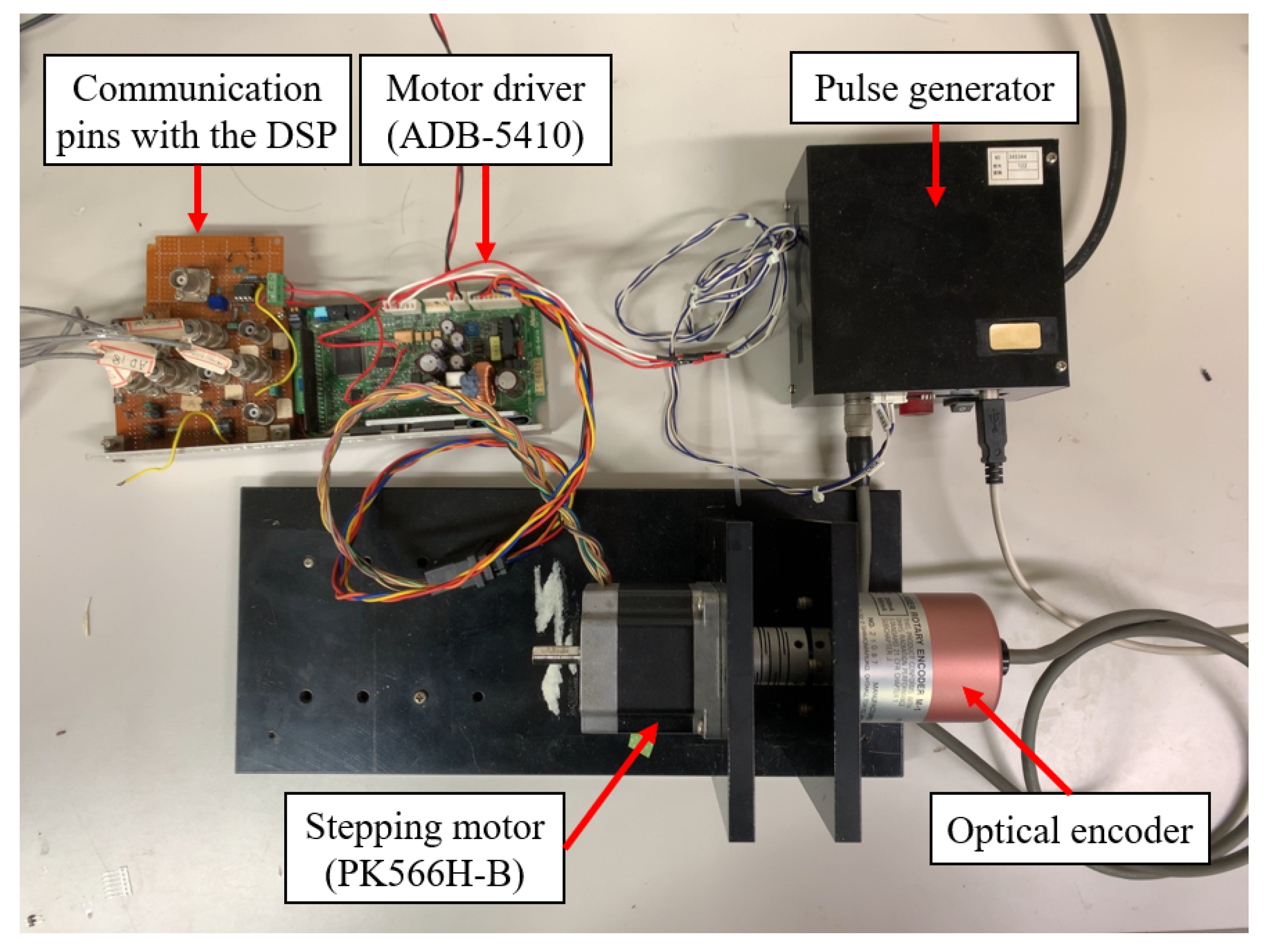
In this study, we consider a system consisting of a 5-phase HB (Hybrid) stepping motor (PK566H-B: Oriental Motor Corporation) and a driver (ADB-5410: Melec Corporation). The system configuration is shown in Figure 1.
The ADB-5410 driver is commercially available and mainly consists of an excitation sequencer, a reference generator, and a current controller. The excitation sequencer determines the rotation angle and angular velocity of the motor by distributing the currents flowing to the coils, which is used to rotate the motor, in response to the input pulses. The reference generator compensates for the effect of the back EMF caused by the rotational speed and is designed to reduce the unevenness in torque. It is also composed of analog elements inside the ADB-5410.
The motor system has separate I/O (Input/Output) terminals connecting to a PC via a DSP (Digital Signal Processor) board (DS1103: dSPACE Corporation). The DS1103 board is equipped with I/O terminals and an ADC (Analog/Digital Converter), which allows us to implement the digital control algorithm for the current control unit designed by Matlab/Simulink directly without manual coding.

3.2. Current Controller

The current controller is used to control the current of the coil at an appropriate value to obtain a user-specified torque. This is because the coil of each phase in the stepping motor is an inductive load, which composes a series of inductances and resistance. The inductive load delays the rise time of the current, which is determined by the excitation sequencer. This delay time between the actual current flowing through the coil winding of the motor and the input pulses increases when the frequency of the input pulse increases. As a result, the response of the motor is usually poor in the high-speed range. In addition, the excess of the excitation current in the high-speed range may cause the motor and the driver to generate ineffectual heat [30]. Thus, controlling the current accurately plays an important role in improving the accuracy of the motor.

3.3. Plant and Current Controller

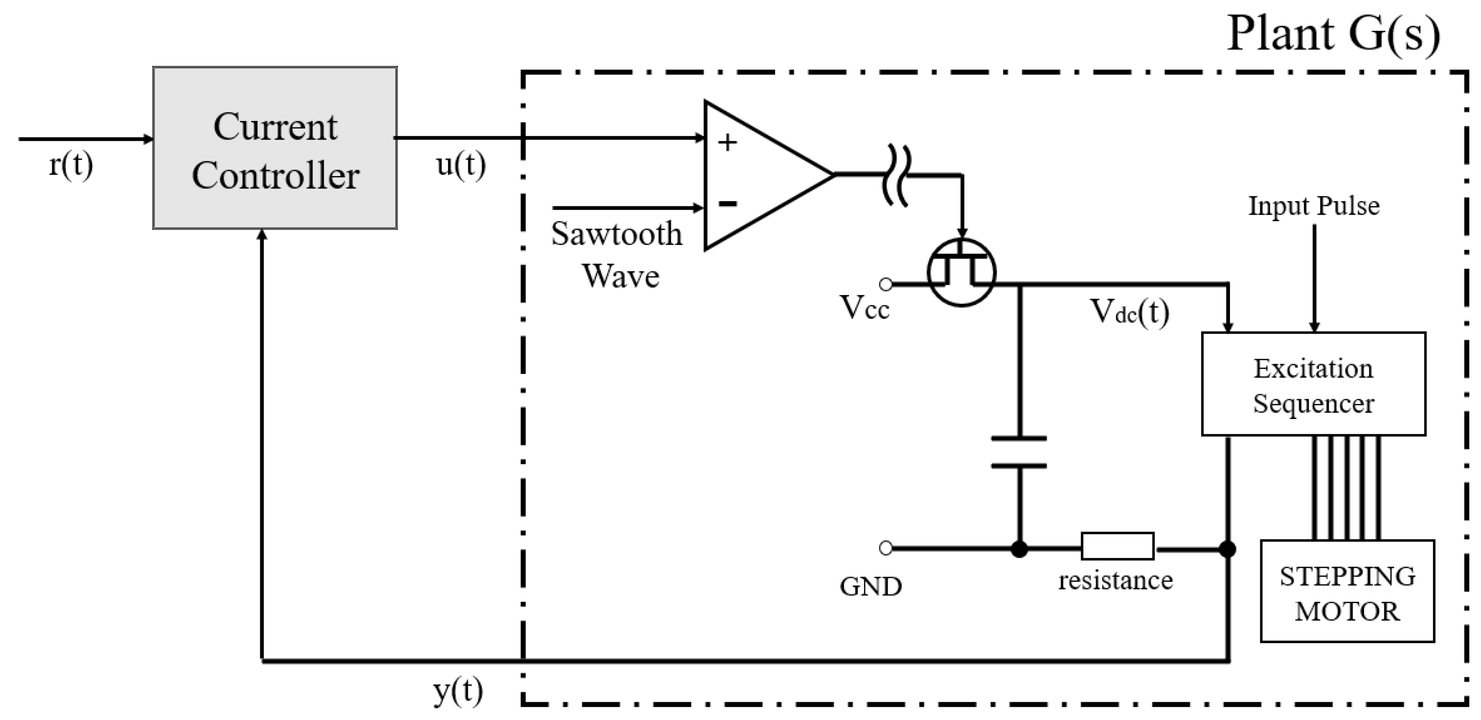
A five-phase stepping motor and driver are a multi-input-multi-output (MIMO), non-linear system. However, we treat the area indicated by the dotted line as a plant, as shown in Figure 2.
The motor driver ADB-5410 uses the all-phase batch driving system, in which the input voltage of the five phases of the motor coils is centrally controlled by the output capacitor. By using this method, the plant can be considered as a single-input-single-output (SISO) system from the viewpoint of the current controller.
The output voltage y ( t ) is expressed as the product of the shunt resistance and the current flowing in the excitation coils of all five phases. When the motor rotates, the output voltage y ( t ) decreases due to the effect caused by the coil inductance and the back EMF, which depends on the speed of the motor. In this study, the motor with the variable rotation speed can be considered as a time-varying system. The control target is to keep the output voltage y ( t ) tracking a reference voltage r ( t ) , which is generated by the reference generator.
The plant model G ( s ) of the motor system is derived by using a system identification method as [31]
G ( s ) = 2.5 × 10 4 s 2 + 8.8 × 10 6 s + 1.8 × 10 10 s 3 + 4.5 × 10 3 s 2 + 8.2 × 10 6 s + 4.3 × 10 9 .
It should be noted that all poles and zeros of this identified plant model are stable. This stability enables us to use the inverse model of the plant as part of a discrete-time PITF while redesigning the digital controller.
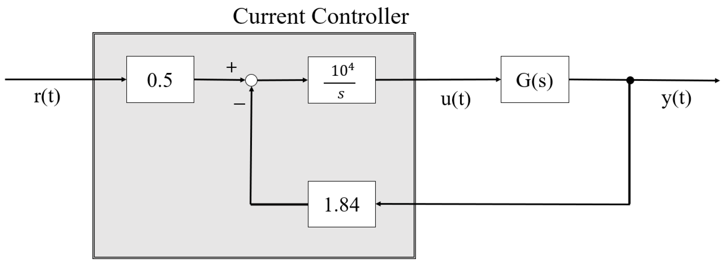
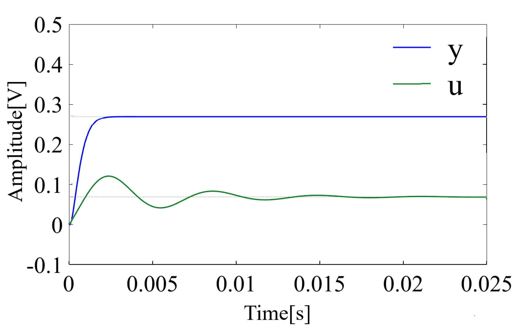
The analog control system for the motor current in the driver ADB-5410 is shown in Figure 3. A digitalization of this analog controller is described in Section 3.4. An integrator in this current control system is designed to remove the deviation between the steady-state of the output voltage y ( t ) and the reference voltage r ( t ) . In the conventional analog driver, the acceleration performance and the speed fluctuation suppression performance are tuned by adjusting the gain of the integrator via a capacitor within the range of 600–10,000 physically. Figure 4a,b shows the step responses of plant input u and the output voltage y with the integrator gain of 600 and 10,000, respectively. It can be seen that achieving high performance for both acceleration and speed fluctuation suppression characteristics simultaneously is a challenge and is a trade-off of the analog controller.

3.4. Digital Control System Design by Direct PIM Method

In this study, a digital controller is redesigned from the analog controller by using the direct PIM method, as shown below [32]. Figure 5 shows a structure of the digital controller, where G ( ε ) is a step-invariant discrete-time model of the continuous-time plant, where G ( s ) , A ( ε ) , B ( ε ) , and C ( ε ) are discrete-time control blocks that need to be determined.
Applying the transformation given by Equation (3) to the continuous-time plant G ( s ) given by Equation (4), we can derive the step-invariant discrete-time model G ( ε ) as
G ( ε ) = 1.5 × 10 4 ε 2 + 7.6 × 10 6 ε + 1.0 × 10 10 ε 3 + 4.0 × 10 6 ε 2 + 5.7 × 10 6 ε + 2.5 × 10 9 .
The stepping motor usually rotates in synchronization with a pulse signal. However, unreasonable acceleration/deceleration or a change of load torque may cause a phenomenon called “loss of synchronism” [1], in which the synchronized rotation is lost. In practice, the loss of synchronism often occurs during the acceleration and deceleration processes. A lack of torque during a rise time of the voltage has been pointed out as a cause for the loss of synchronism [31]. Thus, the controller needs to be designed such that the input voltage of the stepping motor has a sufficiently fast rise time.
At the same time, in order to lengthen the lifespan of electronic elements such as an operational amplifier, an inadvertent overshoot or undershoot is undesired. Thus, a time response close to that of the reference model can be considered as an ideal response of the closed-loop in the stepping motor system.
There are various methods for determining the characteristic polynomial, such that the closed-loop system has a behavior close to that of the reference model. In this study, the Bessel polynomial [33] is used to determine the characteristics of the discrete-time PITF. The Bessel polynomial is determined with a band-width of 400 ( Hz ), which is 1 / 10 of the sampling frequency. At this frequency, the group delay is approximately constant. As a result, the discrete-time PITF is obtained as
M ( ε ) = u ( ε ) r ( ε ) = 1.5 × 10 6 ε 3 + 8.8 × 10 3 ε 2 + 2.7 × 10 7 ε + 2.9 × 10 10 G ( ε ) 1 .
Following a design process of the PIM method, by solving a Diophantine equation, we can obtain the control blocks A ( ε ) , B ( ε ) , and as C ( ε ) as
A ( ε ) = 1.5 × 10 6 λ ( ε ) ,
B ( ε ) = 0.33 ε 2 + 1.5 × 10 3 ε + 1.8 × 10 6 λ ( ε ) ,
C ( ε ) = λ ( ε ) ε 2 + 5.1 × 10 2 ε + 6.8 × 10 7 ,
respectively, where λ ( ε ) is an arbitrary stable observer polynomial. In this study, λ ( ε ) is determined such that the observer poles are placed at ten times the sampling period T in the Euler plane and given by
λ ( ε ) = ( ε + 4.0 × 10 2 ) 2 .
Figure 6 shows the step response of the closed-loop system with the above controller designed by the direct PIM method. The response has a fast rise-time without overshoot.
Comparing Figure 4b and Figure 6, it can be confirmed that the closed-loop system obtained by the direct PIM digital design method has better performance in settling time and transient characteristics than the analog controller.
In applications, if the motor system is driven at a low-speed range, the position accuracy is a high priority, while the acceleration performance may not be a required index. On the other hand, if the system needs to be driven in a high-speed range to reach to the target speed as soon as possible, it is required to prevent the system from stalling during acceleration. Since the requirement for the acceleration and speed fluctuation characteristics of the system may be changed due to the applications of the motor, the digital controller needs to be designed again to achieve that requirement. This process may increase the cost of the development phase. Therefore, it is desirable to separate the design of the closed-loop system to compensate for the stability from the change of the required characteristics of the system while achieving constant current control.
In this paper, as a countermeasure to this problem, we use a control structure that is an extension of the constant current control method with variable adaptive gain proposed by Yagi et al. [16]. This control structure is a two-degrees-of-freedom system, and after creating a stable closed-loop system, the characteristics of the entire system can be changed by adjusting the gain in the adaptive mechanism, which is the outer loop. A detailed description of this control structure is given in Section 4.

4. Removal of Steady Deviations by Adaptive Gain Based on PI Regulator

4.1. Proposed Control Structure

The dynamics of a plant degenerates depending on the motor speed. In the analog controller, the change in the characteristics is controlled by an integrator in the current controller, which follows the target value without deviation. The direct PIM method, on the one hand, is a global digital design method, and therefore, the characteristics of individual analog controller blocks are not preserved. Therefore, the digital controller designed by the direct PIM method does not include an integrator, and when the digital controller is used as is in the control calculation section, the desired control can only be achieved around the rotation speed at which the model for direct PIM design was created. Therefore, the digital controller must be designed for each rotation speed, and the direct PIM design model required for the direct PIM method must be different for each rotation speed.
In this paper, we propose a PI adaptive control structure to remove the steady deviation of the motor. In this method, the closed-loop system is a two-degrees-of-freedom structure, where adaptive gains are used as feed-forward compensators. In general cases, the steady deviations can be removed by adding an integral element into the feedback control system following the principle for the internal model [17]. However, in this method, the removal of the steady deviation is achieved by the variable adaptive gain despite the characteristics of the feedback system.
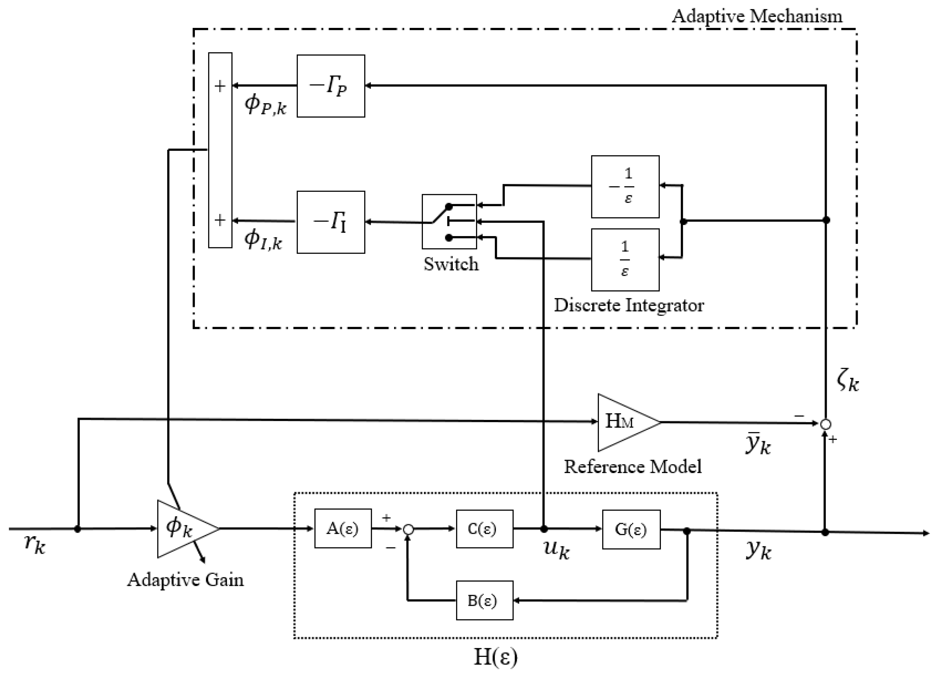
Figure 7 shows the structure of the proposed control system, where the adaptive gains are added to the digital control system designed by the direct PIM method. The adaptive mechanism is designed to ensure that the deviation between the steady-state of the output and the reference input converges to zero by tuning adaptive gain online.
In the analog control system shown in Figure 3, the transfer function H ( s ) of the closed-loop system can be calculated as
H ( s ) = 0.5 G ( s ) s 10 4 + 1.84 G ( s ) .
By noting that the integral gain is set at a relatively large value of 10 4 , the transfer function H ( s ) can be approximated as
H ( s ) 0.5 G ( s ) 1.84 G ( s ) = 0.5 1.84 ,
when the response is considered in a low-frequency region. Equation (12) means that the transfer function of the analog circuit used in the experiment can be treated as a gain in the low-frequency region. The low-frequency region in this study is defined as less than 100 ( Hz ). The analysis of the power spectrum of the reference voltage shows that it is almost flat over the entire frequency range. In this case, the power spectrum of the output signal is equal to the gain characteristic of H ( s ) . Therefore, gain approximation is achieved by configuring the control system with the output signal through a first-order low-pass digital filter, which is given by
F ( ε ) = ( 1.0 × 10 2 ) ( ε + 1.0 × 10 2 ) .
Thus, the reference model of the closed-loop system, which is the ideal transfer function from r ¯ k to y ¯ k , can be approximated as
H M = 0.5 1.84 .
The output signal is affected by the back EMF depending on rotation speed. In this case, the value of the output, which can be obtained for the same value of the reference signal, is reduced. If the gain approximation is realized, this effect can be treated by decreasing the closed-loop steady-state gain. In the designed digital current controller, the adaptive gain is added to the closed-loop system in a feed-forward manner. It compensates for the decrease of the steady-state gain.

4.2. Adaptive Gain Update Rule

In the plant of the motor shown in Figure 2, the comparator, to which the output u k of the controller is the input, has a physical saturation factor. When the input u k is saturated, the control deviation accumulates and leads to a divergence phenomenon called windup. As a countermeasure to this problem, the integral adjustment law of the adaptive mechanism suppresses the windup by using a switch with a threshold value of u sat , the saturation value of the plant input. This switching structure prevents the adaptive gain from diverging [16].
Let ζ k be an error between the output of the real closed-loop system y k and the output of the reference model y ¯ k , defined by
ζ k = y k y ¯ k .
The steady deviation tuning gain ϕ k is updated adaptively by the following law
ϕ k = Γ P ζ k + Γ I ε sgn ( | u sat | | u k | ) ζ k ,
where Γ P , Γ I are positive gains of the PI regulator, and sgn ( | u sat | | u k | ) is a sign function defined by
sgn ( | u sat | | u k | ) = + 1 , ( | u sat | | u k | 0 ) , 1 , ( | u sat | | u k | < 0 ) .
Theorem 1.
When the gains Γ P and Γ I satisfy the following condition, for the non-saturated input, the closed-loop system showed in Figure 7 is stable
Γ I < 2 ( 1 + Γ P H | | r k | | ) T H | | r k | | ,
where T is sampling interval and | | r k | | is a supremum of the system input r k .
Proof. 
Following the block diagram shown in Figure 7, the error between the outputs of the real closed-loop system and the reference model given by Equation (14) can be written as
ζ k = ϕ k H r k H M r k
= ϕ k H M H H r k
= η k H r k ,     
where η k is defined as
η k = ϕ k H M H .
Consider a Lyapunov candidate function V k , given by
V k = η k 2 .
Then, V k is a positive definite function. The derivative of V k is given by
δ V k = η k + 1 2 η k 2 T .
By noting that
δ η k = η k + 1 η k T ,
Equation (23) can be written as
δ V k = δ η k ( T δ η k + 2 η k ) .
Taking derivative both sides of Equations (16) and (20), we have
δ ϕ k = Γ P δ ζ k + Γ I sgn ( | u sat | | u k | ) ζ k .
δ ζ k = H r k δ η k .
Substituting Equations (20) and (27) into (26) gives
δ ϕ k = H r k Γ P δ η k + Γ I sgn ( | u sat | | u k | ) η k .
By noting that H M H is constant, from Equation (21), we obtain
δ ϕ k = δ η k .
Substituting Equation (29) into Equation (28) gives
δ η k = H r k Γ P δ η k + Γ I sgn ( | u sat | | u k | ) η k .
Solving for δ η k in Equation (30), we have
δ η k = Γ I H r k η k 1 + Γ P H r k sgn ( | u sat | | u k | ) .
Substituting Equation (31) into Equation (25), we have
δ V k = Γ I H r k η k ( 1 + Γ P H r k ) sgn ( | u sat | | u k | ) T Γ I H r k η k ( 1 + Γ P H r k ) sgn ( | u sat | | u k | ) 2 η k
= Γ I H r k η k 2 ( 1 + Γ P H r k ) 2 T Γ I H r k 2 ( 1 + Γ P H r k ) sgn ( | u sat | | u k | ) .    
For the non-saturated input, i.e., | u k | | u sat | , we have
δ V k = Γ I H r k η k 2 ( 1 + Γ P H r k ) 2 T Γ I H r k 2 ( 1 + Γ P H r k )
= Γ I H r k η k 2 ( 1 + Γ P H r k ) 2 ( T Γ I 2 Γ P ) H r k 2 ) .
Since r k | | r k | | , when the control gains Γ P and Γ I satisfy the condition given by Equation (35), we have
( T Γ I 2 Γ P ) H r k 2 ( T Γ I 2 Γ P ) H | | r k | | 2 < 0 .
By noting that Γ I H r k / ( 1 + Γ P H r k ) 2 > 0 and η k 2 0 , we can derive that
δ V k = 0 for η k = 0 , δ V k < 0 for η k 0 .
The function V k defined by (22) is positive definite and its derivative is negative definite, thus, V k is a Lyapunov function, and η k 0 , i.e., ζ k 0 is guaranteed. Therefore, satisfying with the condition of | u k | < | u sat | and using (16) as the executable of the variable gain update rule defined in (26), the convergence of (15) to 0 is guaranteed for all T.
Figure 8 shows areas where the closed system is stable with regard to the control parameters Γ P and Γ I with various values of the sampling interval T. For a given supremum of the system input | | r k | | , the smaller the sampling period is, the wider the stability area becomes. □

5. Experimental Results

The experiments were carried out to evaluate the proposed control method. Figure 9 shows the setup of the experiment. The stepping motor and its driver used in the experiments were explained in Section 3. The analog current controller, a part of the driver, was replaced by the proposed digital controller, which is implemented on a DSP with a sampling frequency of 4 ( k Hz ). The parameters for the trapezoidal drive are shown in Table 1.
The maximum reference voltage of the motor system used in the experiments is 2 ( V ). Experiments were carried out to compare the responses of the proposed controller with that of the commercial analog driver. The motor was controlled to have a rotation speed of 6 ( rad / s ) .
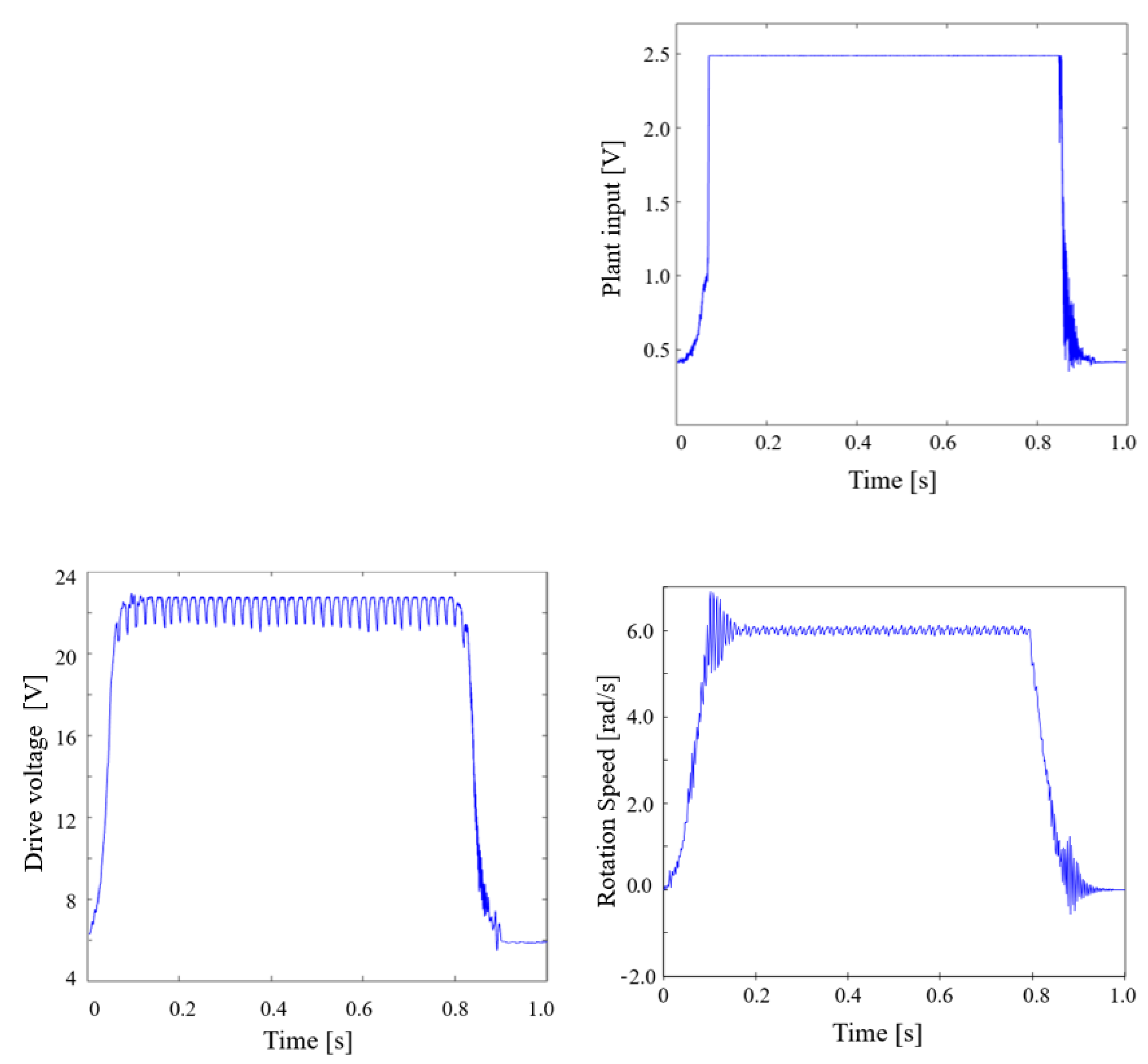
Figure 10 shows the plant input u k , the drive voltage V dc , and the rotational speed v k of the motor for the analog driver. The integration gain of the analog driver was set at 10,000. It can be seen that the plan input of the analog drive is saturated at 2.5 ( V ) corresponding to the maximum reference voltage of the operational amplifier. The saw-tooth wave compared with the operational amplifier in Figure 2 is 0.2 ( V ) at the lower end and 1.0 ( V ) at the upper end, indicating that the plant input exceeds the upper limit of the saw-tooth wave. At this time, the operational amplifier is in a state of constant amplification, which is not desirable considering the lifetime of the circuit element.
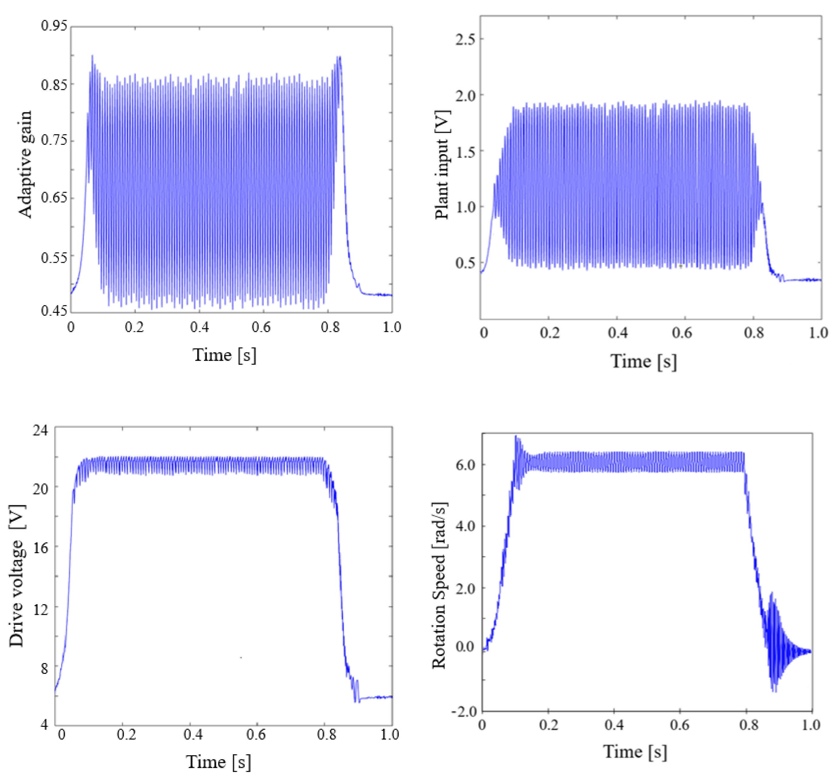
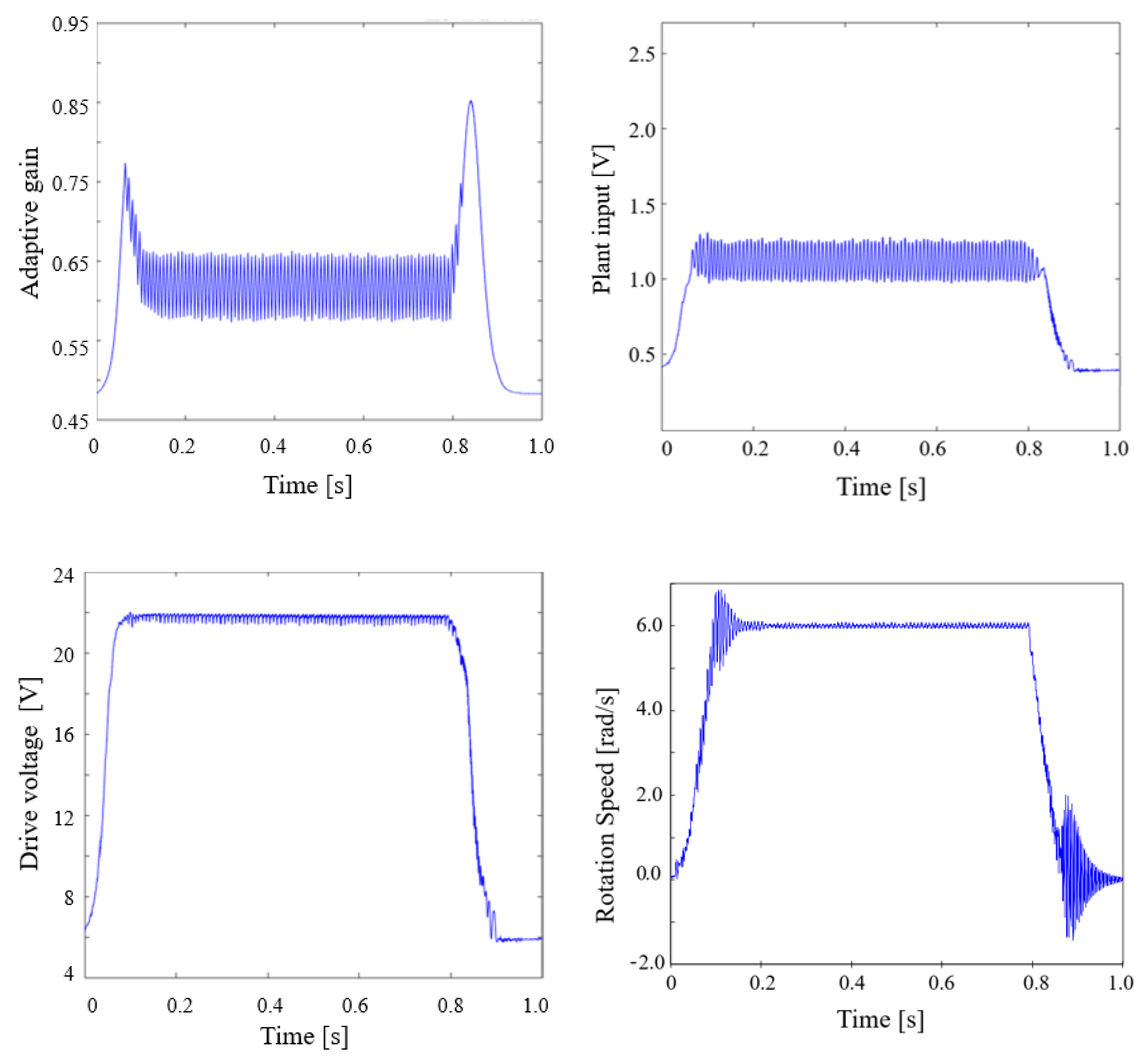
Figure 11 and Figure 12 show the plant input, the drive voltage, the rotational speed, and the adaptive gain ϕ k of the proposed method for I regulator ( Γ P = 0 , Γ I = 500 ) and the PI regulator ( Γ P = 0.5 and Γ I = 100 ), respectively. These control gains are tuned by trial and error to derive the smallest speed fluctuation by referring to the direction of the Ziegler–Nichols tuning method and satisfied the condition for the stability shown by Theorem 1. It can be seen in Figure 11 that the proposed method with only I regulator can improve the windup of the plant input that occurred with the analog controller. However, there are harmonic oscillations appearing on the plant input and the drive voltage. As a result, there is an oscillation accompanying the output rotational speed even for the steady-state.
On the other hand, the proposed method with the PI regulator can suppress the chattering of the drive voltage signal occurring with the P regulator and yield a stable rotational speed. By reducing the value of Γ I , the convergence of the output responding to the reference voltage is slowed down and the torque at high-speed is reduced; however, the convergence to the reference voltage can be compensated by introducing Γ P .
Table 2 shows standard deviations during the steady-state (the period from 0.2 ( s ) to 0.75 ( s ) ) and time constants of the rotation speed for the analog and the proposed controllers. The time constant is defined by the period that the rotation speed reaches 63 % of the steady-state at 6 ( rad / s ) . The proposed method with the adaptive PI regulator reduces about 43.5 % of the standard deviation while raising the time constant of the analog controller by about 8.3 % .

6. Conclusions

In this paper, a digital control method has been proposed for stepping motors. The original digital control loop is designed by using the direct PIM method. A PI adaptive control loop is added to the original control loop in a parallel way to remove the steady deviation of the motor and suppress the physical saturation factor inside the plant. A condition for the gains of the PI regulator ensuring the stability of the closed-loop is derived and proven theoretically using Lyapunov stability theory. Experiments have been carried out to assess the proposed controller. The experimental results show that the proposed controller gives good performance in controlling the rotation speed and deceleration in the high-speed range without affecting the acceleration performance of the given stepping motor. The proposed controller is shown to be able to improve the saturation problem occurring in the analog controller.

Author Contributions

Conceptualization, D.I., K.Y and N.H.; methodology, D.I. and K.Y. and N.H.; validation, D.I., S.K. and T.N.-V.; writing—original draft preparation, D.I, S.K. and T.N.-V.; writing—review and editing, D.I., S.K. and T.N.-V.; supervision, T.N.-V. All authors have read and agreed to the published version of the manuscript.

Funding

This research received a financial and technical support from Melec Corporation.

Data Availability Statement

Data sharing is not applicable to this article.

Conflicts of Interest

The authors declare no conflict of interest.

References

  1. Acarnley, P. Stepping Motors: A Guide to Theory and Practice, 4th ed.; Control, Robotics and Sensors; Institution of Engineering and Technology: London, UK, 2002; p. 172. [Google Scholar] [CrossRef]
  2. Nishiyama, Y.; Nakamura, M.; Henmi, C.; Yamaguchi, K.; Mochizuki, S.; Nakagawa, H.; Takiura, K. Development of a Three-Dimensional Bioprinter: Construction of Cell Supporting Structures Using Hydrogel and State-of-the-Art Inkjet Technology. J. Biomech. Eng. 2009, 131. [Google Scholar] [CrossRef]
  3. Utada, A.S.; Lorenceau, E.; Link, D.R.; Kaplan, P.D.; Stone, H.A.; Weitz, D.A. Monodisperse Double Emulsions Generated from a Microcapillary Device. Science 2005, 308, 537–541. [Google Scholar] [CrossRef] [Green Version]
  4. Gu, Z.; Fu, J.; Lin, H.; He, Y. Development of 3D Bioprinting: From Printing Methods to Biomedical Applications. Asian J. Pharm. Sci. 2020, 15, 529–557. [Google Scholar] [CrossRef]
  5. Xu, W.; Kaizheng, H.; Bin, X. Design for Step Motor Control System of Automatic Biochemistry Analyzer. In Proceedings of the 2007 8th International Conference on Electronic Measurement and Instruments, Xi’an, China, 16–18 August 2007; pp. 1-607–1-612. [Google Scholar] [CrossRef]
  6. Whitesides, G.M. The Origins and the Future of Microfluidics. Nature 2006, 442, 368–373. [Google Scholar] [CrossRef]
  7. Stone, H.; Stroock, A.; Ajdari, A. Engineering Flows in Small Devices: Microfluidics toward a Lab-on-a-Chip. Annu. Rev. Fluid Mech. 2004, 36, 381–411. [Google Scholar] [CrossRef] [Green Version]
  8. Li, Z.; Mak, S.Y.; Sauret, A.; Shum, H.C. Syringe-Pump-Induced Fluctuation in All-Aqueous Microfluidic System Implications for Flow Rate Accuracy. Lab Chip 2014, 14, 744–749. [Google Scholar] [CrossRef] [PubMed] [Green Version]
  9. Zeng, W.; Jacobi, I.; Beck, D.J.; Li, S.; Stone, H.A. Characterization of Syringe-Pump-Driven Induced Pressure Fluctuations in Elastic Microchannels. Lab Chip 2015, 15, 1110–1115. [Google Scholar] [CrossRef] [PubMed]
  10. Taniguchi, T.; Ohtsuka, K.; Takasugi, K. Rotor Oscillation Damping of a Stepping Motor by the Method of a Simple Switching Sequence. IEEJ Trans. Ind. Appl. 1991, 111, 497–498. (In Japanese) [Google Scholar] [CrossRef] [Green Version]
  11. Miura, T.; Taniguchi, T. Tuning of Exciting Period for a Stepping Motor by Regulator. IEEJ Trans. Ind. Appl. 1996, 116, 800–801. (In Japanese) [Google Scholar] [CrossRef] [Green Version]
  12. Senjyu, T.; Nakahama, S.; Uezato, K. Damping Method of Rotor Oscillation for Variable Reluctance Type Stepping Motor Using Fuzzy Reasoning. IEEJ Trans. Ind. Appl. 1994, 114, 346–347. (In Japanese) [Google Scholar] [CrossRef] [Green Version]
  13. Senjyu, T.; Nakahama, S.; Uezato, K. Rotor Oscillation Damping for Stepping Motors by Inverse Phase Excitation with Fuzzy Reasoning. IEEJ Trans. Ind. Appl. 1996, 116, 1238–1245. (In Japanese) [Google Scholar] [CrossRef] [Green Version]
  14. John, P. Reducing Position Errors by Vibration Optimization of Stepper Motor Drive Waveforms. IEEE Trans. Ind. Electron. 2021, 68, 5176–5183. [Google Scholar] [CrossRef]
  15. Stefano, R.; Valentino, M. Simple Torque Control Method for Hybrid Stepper Motors Implemented in FPGA. Electronics 2018, 7, 242. [Google Scholar] [CrossRef] [Green Version]
  16. Yagi, K.; Hori, N.; Nahon, M. Experimental Verification of a Practical Digital Driver with Switched Gain-Tuning for Five-Phase Stepping-Motors. Trans. Can. Soc. Mech. Eng. 2015, 39, 239–252. [Google Scholar] [CrossRef]
  17. Francis, B.A.; Wonham, W.M. The Internal Model Principle of Control Theory. Automatica 1976, 12, 457–465. [Google Scholar] [CrossRef]
  18. Astrom, K.J.; Rundqwist, L. Integrator windup and how to avoid it. In Proceedings of the 1989 American Control Conference, Pittsburgh, PA, USA, 21–23 June 1989; pp. 1693–1698. [Google Scholar]
  19. Hung, J.; Gao, W.; Hung, J. Variable structure control: A survey. IEEE Trans. Ind. Electron. 1993, 40, 2–22. [Google Scholar] [CrossRef] [Green Version]
  20. Utkin, V. Variable structure systems with sliding modes. IEEE Trans. Autom. Control 1977, 22, 212–222. [Google Scholar] [CrossRef]
  21. Hirschorn, R. Sliding-Mode Control Variations. IEEE Trans. Autom. Control 2007, 52, 468–480. [Google Scholar] [CrossRef]
  22. Monopoli, R. Model Reference Adaptive Control with an Augmented Error Signal. IEEE Trans. Autom. Control 1974, 19, 474–484. [Google Scholar] [CrossRef]
  23. Aseltine, J.; Mancini, A.; Sarture, C. A Survey of Adaptive Control Systems. IRE Trans. Autom. Control 1958, 6, 102–108. [Google Scholar] [CrossRef]
  24. Andeen, R.E. The Principle of Equivalent Areas. Trans. Am. Inst. Electr. Eng. Part II Appl. Ind. 1960, 79, 332–336. [Google Scholar] [CrossRef]
  25. Middleton, R.; Goodwin, G. Improved Finite Word Length Characteristics in Digital Control Using Delta Operators. IEEE Trans. Autom. Control 1986, 31, 1015–1021. [Google Scholar] [CrossRef]
  26. Middleton, R.H.; Goodwin, G.C. Digital Control And Estimation—A Unified Approach; Prentice Hall: Englewood Cliffs, NJ, USA, 1990; p. 538. [Google Scholar]
  27. Markazi, A.H.D.; Hori, N. A New Method with Guaranteed Stability for Discretization of Continuous-Time Control Systems. In Proceedings of the 1992 American Control Conference, Chicago, IL, USA, 24–26 June 1992; pp. 1397–1402. [Google Scholar]
  28. Sain, M.; Schrader, C. The Role of Zeros in the Performance of Multiinput, Multioutput Feedback Systems. IEEE Trans. Educ. 1990, 33, 244–257. [Google Scholar] [CrossRef]
  29. Hori, N.; Mori, T.; Nikiforuk, P.N. Discrete-Time Models of Continuous-Time Systems; Academic Press: London, UK, 1994; Volume 66, pp. 1–45. [Google Scholar]
  30. Shen, J.; Qin, X.; Wang, Y. High-Speed Permanent Magnet Electrical Machines—Applications, Key Issues and Challenges. CES Trans. Electr. Mach. Syst. 2018, 2, 23–33. [Google Scholar] [CrossRef]
  31. Yagi, K. Digital Current Regulator for Stepping Motors through Feedforward-Gain Tuning. Ph.D. Thesis, University of Tsukuba, Tsukuba, Japan, 2016. (In Japanese). [Google Scholar]
  32. Kanai, K.; Hori, N. Introduction to Digital Control—Application of Delta Operators; Maki Publisher: Tokyo, Japan, 1992. (In Japanese) [Google Scholar]
  33. Martinez, J.R. Transfer Functions of Generalized Bessel Polynomials. IEEE Trans. Circuits Syst. 1977, 24, 325–328. [Google Scholar] [CrossRef] [Green Version]
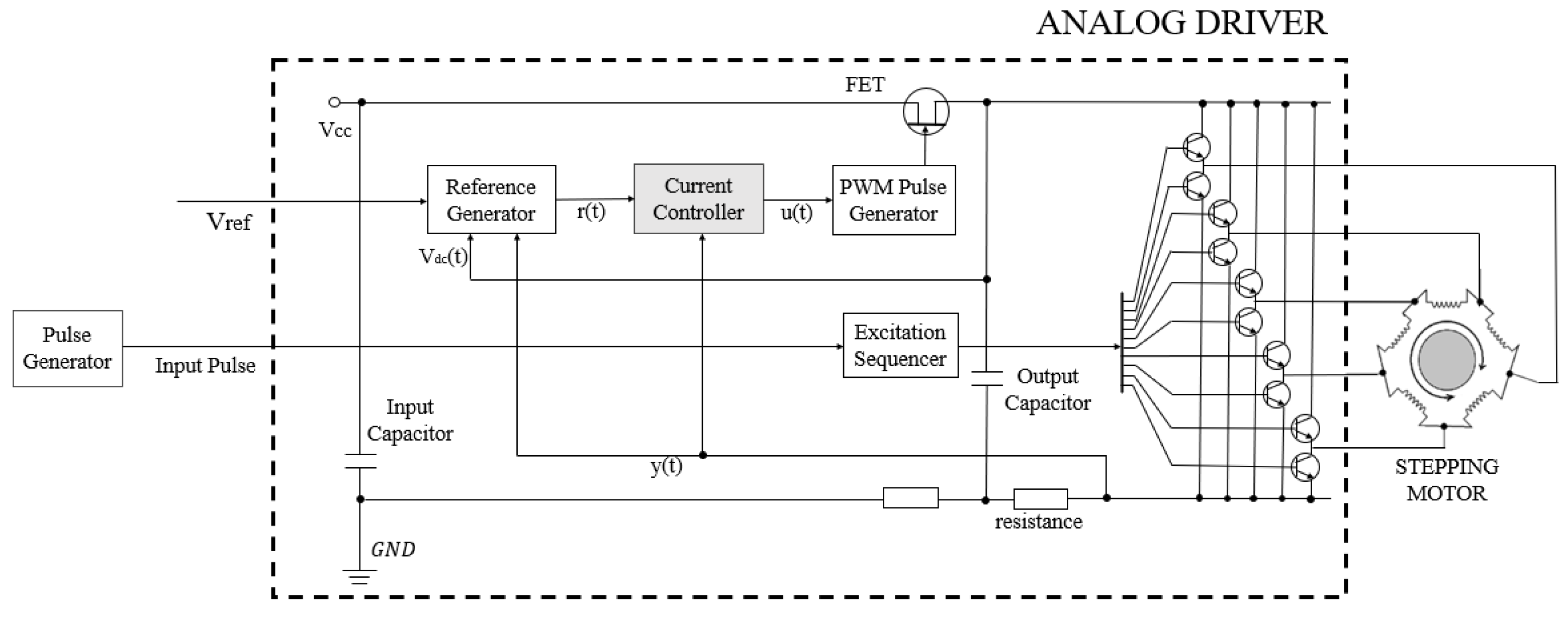
Figure 1. Connection between 5-phase stepping motor to the analog driver (The current controller is implemented by the DSP in the digital controller).
Electronics 10 01335 g001
Figure 2. The plant diagram of the constant current control circuit.
Electronics 10 01335 g002
Figure 3. Block diagram of the constant current control circuit of the ADB-5410.
Electronics 10 01335 g003
Figure 4. Step response of the analog controller.
Electronics 10 01335 g004
Figure 5. Structure of controller design by the PIM method.
Electronics 10 01335 g005
Figure 6. Step response of the digital controller designed by the PIM method.
Electronics 10 01335 g006
Figure 7. Structure of the proposed controller.
Electronics 10 01335 g007
Figure 8. Stability area of the gains Γ P and Γ I .
Electronics 10 01335 g008
Figure 9. Experimental equipment.
Electronics 10 01335 g009
Figure 10. Responses of the analog controller.
Electronics 10 01335 g010
Figure 11. Responses of the proposed method with the I regulator ( Γ P = 0 , Γ I = 500 ).
Electronics 10 01335 g011
Figure 12. Responses of the proposed method with the PI regulator ( Γ P = 0.5 , Γ I = 100 ).
Electronics 10 01335 g012
Table 1. The parameters for the trapezoidal drive.
Starting frequency100 ( Hz )
Maximum frequency3000 ( Hz )
Acceleration rate18 ( m s / k Hz )
Deceleration rate18 ( m s / k Hz )
Total number of pulses2300 (-)
Hold current 0.204 ( A /phase)
Drive current 0.51 ( A /phase)
Step angle 0.72 ( )
Table 2. Standard deviation and time constant of the motor at the steady-state.
Proposer Method
Analog Controllerwith I Regulatorwith PI Regulator
Standard deviation0.0620.0220.035
Time constant [ s ] 0.0720.0780.078
Publisher’s Note: MDPI stays neutral with regard to jurisdictional claims in published maps and institutional affiliations.