Article

Prescribed Performance-Based Event-Driven Fault-Tolerant Robust Attitude Control of Spacecraft under Restricted Communication

1
Department of Electrical Engineering, Indian Institute of Technology Delhi, New Delhi 110016, India
2
Electrical Engineering Department, College of Engineering, Qassim University, Buraydah 51452, Saudi Arabia
*
Author to whom correspondence should be addressed.
Electronics 2021, 10(14), 1709; https://doi.org/10.3390/electronics10141709
Submission received: 4 June 2021 / Revised: 1 July 2021 / Accepted: 5 July 2021 / Published: 16 July 2021
(This article belongs to the Special Issue Control of Nonlinear Systems and Industrial Processes)

Abstract

:
This paper explores the problem of attitude stabilization of spacecraft under multiple uncertainties and constrained bandwidth resources. The proposed control law is designed by combining the sliding mode control (SMC) technique with a prescribed performance control (PPC) method. Further, the control input signal is executed in an aperiodic time framework using the event-trigger (ET) mechanism to minimize the control data transfer through a constrained wireless network. The SMC provides robustness against inertial uncertainties, disturbances, and actuator faults, whereas the PPC strategy aims to achieve a predefined system performance. The PPC technique is developed by transforming the system attitude into a new variable using the prescribed performance function, which acts as a predefined constraint for transient and steady-state responses. In addition, the ET mechanism updates the input value to the actuator only when there is a violation of the triggering rule; otherwise, the actuator output remains at a fixed value. Moreover, the proposed triggering rule is constituted through the Lyapunov stability analysis. Thus, the proposed approach can be extended to a broader class of complex nonlinear systems. The theoretical analyses prove the uniformly ultimately bounded stability of the closed-loop system and the non-existence of the Zeno behavior. The effectiveness of the proposed methodology is also presented along with the comparative studies through simulation results.

1. Introduction

The spacecraft attitude determination and control is an important task in every space mission, viz. space station docking, navigation, planet mapping, communication, etc. While regulating the attitude, the controller has to face many challenges, e.g., uncertainty in the inertia matrix, external disturbances, actuator faults, and saturation and availability of limited measurements. In addition, an ideal attitude control system (ACS) must possess features such as faster response, higher pointing accuracy, energy-efficient, etc. [1]. In the last couple of decades, different attitude control schemes are developed to deal with the above challenges and design criteria. Some of the control strategies explored for ACS are reported in [2,3,4,5,6,7,8,9,10,11], and references therein. These reported works investigate the use of H control [6], sliding mode control (SMC) [2,3,4,5], adaptive control [7,8], backstepping control [9], disturbance observer-based robust control [10,11], etc., for attitude tracking/regulation control problem.
Although the above schemes provide a satisfactory response, the control laws are implemented in a continuous-time framework. In other words, the practical realization of these control schemes requires a digital platform with a significantly small sampling time. However, in a bandwidth constraint spacecraft (e.g., fractionated spacecraft or plug and play spacecraft [12]), the above continuous-time strategies may be ineffective due to the requirement of a high rate of data transfer. Further, the fundamental components of such spacecraft interact with each other through a wireless network. In addition, they have limited communication resources due to the use of low-cost wireless systems for cost-cutting purposes. As a result, continuous-time control strategies that require a high frequency of data sampling will cause overburden on the communication channel and thus unfit for such constrained spacecraft. Moreover, the communication constrained problem becomes severe when multiple satellites interact through a wireless network for space missions, e.g., spacecraft formation in a leader-follower coordination control problem. In this structure, the follower satellites may lack a CPU, and the control construction procedure may be run on a leader satellite. The control signal is then transmitted to the follower satellites that only execute the required actuation. Hence, a constrained communication network will restrict the implementation of a continuous-time control strategy for such multi-agent systems [13]. Therefore, an alternative approach is needed that would exert less stress on the wireless communication channel. This can be achieved by updating the control input aperiodically when there is a need for corrective control action.
Nowadays, two main approaches are prevalent for the control system design under limited communication resources. One is the quantization technique, and another one is the event-trigger (ET) mechanism. The basic principle of the quantization technique is the discretization of the continuous input signal into a set of finite discrete levels [14]. The method of discretization can be carried out through different quantization approaches, e.g., linear, logarithmic, hysteresis, and hybrid [15,16,17]. Although this technique reduces the communication burden with satisfactory system performance, the steady-state chattering problem exists in the quantized output response [18]. Further, the data transmission has a continuous-time framework between the sensor and controller modules.
On the other hand, the event-trigger strategy updates the control law only at the time instants when a specific error crosses a threshold function level [19,20,21,22]. The control output is kept at a fixed value between the two adjacent triggering instances. As a result, the number of control updates between the controller and actuator modules gets reduced. Subsequently, it brings down the overload of the wireless communication network [23,24,25]. Some of the early results on the ET control strategies are reported in [26,27]. In these papers, the input-to-state stability with respect to the ET-induced error is assumed without analysis. Such an assumption is difficult to be valid for a complex nonlinear system, like satellite attitude dynamics. The said assumption is relaxed in [28], where an adaptive-based ET mechanism is proposed. However, the control design in [28] is restricted to SISO systems, and the direct extension of this control approach to MIMO systems with coupling dynamics (e.g., spacecraft) is laborious to achieve. Lately, the ET-based attitude control strategies are also explored for the spacecraft problem in [29,30,31,32,33,34,35]. In [29,30,31,32], the ET schemes with non-adaptive control are proposed, where apriori upper bound knowledge of disturbance is assumed. Thenceforth, adaptive-based ET is presented in [33,34] using backstepping and fuzzy-based SMC schemes, respectively, to avoid the disturbance assumption. However, the control design in [29,30,31,32,33,34] did not explore the possibility of actuator faults that may deteriorate or destabilize the system performance. Consequently, a fault-tolerant ET scheme is presented in [35], which regulates the spacecraft attitude by employing an adaptive-based fuzzy logic control. In these schemes, triggering conditions are based on either predefined fixed value or relative triggering threshold function [25]. As a result, the extension of these ET strategies to other dynamical systems is not straightforward; thus, it restricts the prospect of their widespread application.
In addition, the aforementioned strategies rely on the repeated tuning of control parameters to achieve desired dynamic response and prespecified steady-state accuracy. The accurate predefined performances are critical for missions like earth observation and deep space asteroid tracking. The best way to obtain the desired transient and steady-state responses is to incorporate the prescribed performance control (PPC) method, which was first proposed in [36]. This method has the attributes of achieving the pre-established desired rate of convergence, overshoot, and steady-state accuracy by transforming the system state into a new error variable using the prescribed performance function (PPF). Owing to the advantages PPC method, the control researchers have also explored this technique for spacecraft problems in [37,38,39,40], and references therein. However, the control schemes in these papers are developed within the framework of a continuous-time update. Very few investigations are done with the PPC-based ET scheme, and the work in [41] is one of them. In [41], an adaptive-based ET control with the PPC method is explored to develop an attitude tracking control for the spacecraft. However, the control formulation using the backstepping method is complex and involves a tedious task of comprehensive theoretical analysis.
In view of the preceding literature, this work investigates the sliding mode control-based PPC method using the ET mechanism for the attitude regulation of spacecraft. Thus, the proposed strategy maintains the benefit of SMC for providing a simple, robust control design, and the PPC provides the prescribed state performance. Moreover, the application of the ET strategy minimizes the usage of communication resources. The key features of this paper are listed below:
  • A robust attitude regulation control using an SMC-based PPC technique is proposed to tackle model uncertainties, disturbances, and actuator faults for the spacecraft system.
  • The PPF enables the spacecraft to achieve a predefined transient and steady-state response without repeated tuning of control parameters.
  • The constraint on the communication network is also considered while designing the control law. Therefore, an event trigger strategy is integrated with the proposed PPC-based SMC scheme. Moreover, the event-triggering rule is established using the negative definiteness rule of the Lyapunov theory, unlike [29,30,31,32,33,34], where a predefined relative threshold function is used. Therefore, the proposed ET approach is more promising and convenient for other sets of dynamics as well.
  • The theoretical analysis establishes the convergence of sliding surface, transformed attitude state, and state trajectories. The overall closed-loop system analysis under the ET-based PPF-SMC strategy guarantees the uniformly ultimately bounded (UUB) convergence of the preceding signals. Moreover, precluding the Zeno phenomenon is also proved under the proposed ET strategy.
The rest of the paper is organized in the following way. Section 2 presents the kinematic and dynamic equations of the attitude of spacecraft under various uncertainties. The proposed problem statement is also mentioned in this section. Section 3 describes the PPF and the transformation of the attitude parameter into a new set of variables. The proposed SMC law and stability analysis without ET mechanism is demonstrated in the Section 4. In Section 5, the event triggering rule is devised, and the overall stability analysis is presented. Section 6 and Section 7 discuss the comparative simulation results and the conclusion of the paper, respectively.

2. Attitude Model of Spacecraft

In this paper, the attitude of spacecraft is parameterized using unit quaternion, which is expressed in terms of scalar q 0 and vector q v components. Jointly, they can be denoted as [42]
q = ( q 0 , q v T ) T , and q v = [ q 1 q 2 q 3 ] T .
The unit quaternion also satisfies the relation (2) for all time
q 0 2 ( t ) + q v T ( t ) q v ( t ) = 1 .

2.1. The Attitude Model of Spacecraft

The attitude of spacecraft is always defined with respect to (w.r.t.) some inertial frame of reference I using unit quaternion. The equation of motion for the spacecraft attitude kinematics w.r.t. reference frame I is defined as [1]:
q ˙ 0 = ( 1 / 2 ) q v T w ,
q ˙ v = Q ( q ) w ,
where Q ( q ) = ( 1 / 2 ) ( q 0 I + q v × ) R 3 × 3 , I is an identity matrix, and w R 3 represents the angular velocity vector. The notation ( · ) × denotes for the skew symmetric matrix for the corresponding vector, and for any z = [ z 1 z 2 z 3 ] T , z × is defined as:
z × = 0 z 3 z 2 ; z 3 0 z 1 ; z 2 z 1 0 .
The attitude dynamics of spacecraft is given as [1]:
J 0 w ˙ = w × J 0 w + u c + d ,
where J 0 R 3 × 3 is the nominal inertia matrix, u c R 3 is the computed control input, and d R 3 is the total disturbance, comprises of actuator faults, external disturbance ( d 0 ), and model uncertainties. The expression of d is given as [43]:
d = J 0 Δ J ^ u + J 0 J 1 ( d 0 + u f ) w × Δ J w J 0 Δ J ^ w × J w
where Δ J R 3 × 3 is uncertainty in inertia matrix, J = J 0 + Δ J [7], Δ J ^ = J 0 1 Δ J ( I 3 × 3 + J 0 1 Δ J ) 1 J 0 1 , u = u c + u f , and u f is the actuator fault, which is defined as u f = F ( t ) + ( E ( t ) I ) u c [44]. Here, F ( t ) R 3 and E ( t ) = diag [ a 1 ( t ) a 2 ( t ) a 3 ( t ) ] represent the bounded additive fault and the effectiveness matrix of the actuators, respectively. The variable a i ( t ) ( 0 , 1 ] for i = 1 , 2 , 3 indicates the health of the individual actuator. Therefore, a i ( t ) = 1 signifies that the ith axis actuator is working perfectly, whereas 0 < a i ( t ) < 1 indicates the unhealthy condition of the actuator. The fading of actuation might occur due to the partial loss of power [45]. The scenario of total actuator failure is depicted by a i ( t ) = 0 , which is not considered in this paper.
Assumption 1.
The lumped disturbance d is bounded and d d max > 0 .
Assumption 2.
The initial condition q 0 ( 0 ) 0 .
Property 1.
Any positive-definite matrix P R n × n holds the following inequality for a vector v R n
λ min ( P ) v 2 v T P v λ max ( P ) v 2 ,
where λ min ( P ) > 0 and λ max ( P ) > 0 are the smallest and largest eigenvalues of P , respectively.
Property 2.
With the use of the unity constraint (2), the Euclidean norm of matrix Q ( q ) satisfies the following inequality
Q ( q ) 1 2 q 0 I + q v × 1 2 ( q 0 I + q v × ) 1 + 2 2 .

2.2. Control Objectives

This paper has three main control objectives:
  • Design a robust fault-tolerant control for the attitude regulation of the spacecraft under various uncertainties.
  • The transient and the steady-state response of attitude q v should satisfy a priori prescribed performance without repeated attempts in tuning the gain parameters of the control. In other words, the predefined performance measures (rate of convergence, maximum overshoot, accurate steady-state precision) should be achieved.
  • The controller and actuator modules interact with each other minimally to update the control data. Thus, the rate of control update through the restricted communication channel is lesser.
  • All the internal and output signals must be bounded.

3. Design of Prescribed Performance Approach

In this section, the design procedure of the PPC is presented using an exponentially decaying PPF. Therefore, a PPF is defined first, and then a new set of variables is constructed using the PPF to represent the attitude of the spacecraft. The PPF helps in optimizing the convergence response of attitude trajectory, whereas the new transformed variables provide the solution to the complicated problem of abiding state trajectory constraint [39,46].

3.1. Prescribed Performance Function

The PPF is employed to represent the predefined bounds of the attitude that must be respected while executing the control law. These bounds are selected according to the prescribed constraint performance of satellite attitude. The definition of PPF is described as follows:
Definition 1.
[46] A smooth function ϱ ( t ) : R + R + is called the PPF if it satisfies the following statement:
(i)
The ϱ ( t ) > 0 and monotonically decaying.
(ii)
lim t ϱ ( t ) = ϱ > 0 .
In view of Definition 1, an exponentially decreasing function is used as a PPF, and it is expressed as [41]:
ϱ i ( t ) = ( ϱ i 0 ϱ i ) exp i t + ϱ i ,
where ϱ i 0 > 0 and ϱ i ( 0 , ϱ i 0 ) are the initial and final value of ϱ i , respectively, and i > 0 is the decaying rate, for i = 1 , 2 , 3 . Therefore, it can be followed from (8) that ϱ i ( t ) > 0 and monotonically decreasing. In addition, the value of ϱ i ( t ) converges to ϱ i as t . With these observations, it can be deduced from Definition 1 that ϱ i ( t ) , for i = 1 , 2 , 3 , are PPFs.
The parameter values of PPF are pre-designed according to the desired attitude response. The prescribed transient and steady performance of quaternion can be represented in terms of PPF by the following inequality:
ξ ̲ i ϱ i ( t ) < q i < ξ ¯ i ϱ i ( t ) t 0 ,
where q i for i = 1 , 2 , 3 is the component of vector quaternion. The coefficients ξ ̲ i > 0 and ξ ¯ i > 0 represent the prescribed constants. Therefore, restricting the variable q i within above bound (9) is equivalent to guaranteeing the prescribed attitude response. Moreover, the selected values of ξ ̲ i , ξ ¯ i , and i should also satisfy for i = 1 , 2 , 3 :
ξ ̲ i ϱ i 0 < q i ( 0 ) < ξ ¯ i ϱ i 0 , and i = 1 3 ϖ i 2 < 1
where ϖ i : = max { ξ ̲ i ϱ i 0 , ξ ¯ i ϱ i 0 } .
Remark 1.
The desired transient and steady state response of q i can be achieved by appropriately selecting the parameters ξ ¯ i , ξ ̲ i , ϱ i 0 , ϱ i , and i . Therefore, the upper limit of the overshoot and the lower limit of the undershoot are served by ξ ¯ i ϱ i 0 and ξ ̲ i ϱ i 0 , respectively for q i . Further the lower limit of convergence rate for q i is dictated by i and the maximum possible value of the steady-state is decided by ϱ i . In addition, the conditions in (10) can be satisfied simultaneously because of the unity constraint (2) and Assumption 2 [46].

3.2. Attitude State Transformation

Here, the attitude q i with the inequality constraint (9) is transformed into an equivalent unconstrained control problem by introducing a new variable for q i . Therefore, the state q i is first modulated by the following expression
ϑ i ( t ) = q i ( t ) ϱ i ( t ) ,
for i = 1 , 2 , 3 , and ϑ R 3 is the modulated vector. Subsequently, the new transformed variable ε i for i = 1 , 2 , 3 is obtained using the given transformation:
ε i = T i ( ϑ i ) = ln ( ξ ̲ i + ϑ i ) ln ξ ¯ i ϑ i .
The function T i ( · ) : ( ξ ̲ i , ξ ¯ i ) ( , + ) is smooth and strictly increasing and has the following properties:
lim ϑ i ξ ̲ i T i ( ϑ i ) = , and lim ϑ i ξ ¯ i T i ( ϑ i ) = + .
Remark 2.
In light of Equations (12) and (13), if ε i is bounded, then ϑ i ( t ) = q i ( t ) / ϱ i ( t ) is bounded within a compact subset of ( ξ ̲ i , ξ ¯ i ) t 0 , and thus the prescribed constraint (10) holds. Once (10) is satisfied, one can obtain i = 1 3 q i 2 ( t ) < 1 and q 0 ( t ) 0 t 0 since ϖ i 2 < 1 , q T ( t ) q ( t ) = 1 , and q 0 ( 0 ) 0 . Therefore, to ensure the prescribed attitude regulation performance (10) and q 0 ( t ) 0 , the boundedness of ε i becomes important for the controller design [41].
The time derivative of ε i from (12) is
ε ˙ i = T i ( ϑ i ) · d ϑ i d t .
Since ϑ i = q i / ϱ i , therefore the above equation can be expanded as
ε ˙ i = T i ( ϑ i ) · d d t q i ϱ i = T i ( ϑ i ) · q ˙ i ϱ i ϱ ˙ i q i ϱ i 2 = 1 ϱ i T i ( ϑ i ) · q ˙ i ϱ ˙ i ϱ i q i
The above expression can be written in the vector from ε ˙ = [ ε ˙ 1 ε ˙ 2 ε ˙ 3 ] T R 3 with the use of (3b) as
ε ˙ = μ ( q ˙ v ν ) ε ˙ = μ ( Q ( q ) w ν ) ,
where μ = diag ( μ 1 μ 2 μ 3 ) , ν = [ ν 1 ν 2 ν 3 ] T with
μ i = T i ( ϑ i ) · 1 ϱ i , and ν i = ϱ ˙ i ϱ i q i for i = 1 , 2 , 3 .
In view of the above transformation, some valuable conclusions can be outlined as [47,48]
( i ) . | ε i | c i | ϑ i | = c i q i ϱ i for i = 1 , 2 , 3 ,
( ii ) . μ i ( t ) = ξ ¯ i + ξ ̲ i ( ϑ i ( t ) + ξ ̲ i ) ( ξ ¯ i ϑ i ( t ) ) · 1 ϱ i > 0 ,
( iii ) . ϱ ˙ i ϱ i > i > 0 ,
where c i = 4 / ( ξ ¯ i + 1 ) .
Remark 3.
An added benefit of PPF based control scheme is that the desired constraint attitude response is achieved without depending on a priori repeated regulation of gain parameters.
Some crucial concepts, which is used in the subsequent proof, are presented here.
Consider a system (21)
ς ˙ ( t ) = g ( ς ( t ) , t ) , ς ( 0 n ) Ω ς ,
where g ( ς ( t ) , t ) : Ω ς × R R n where Ω ς R n is a non-empty open set. Further, g ( ς ( t ) ) d t exist locally for each fixed ς ( t ) Ω ς . Given system (21), the following definition and lemma are essential for the upcoming theorem.
Definition 2.
[48] The solution of system (21) is maximal if there is no right extension for ς ( t ) with ς ( t ) also being the solution of system (21).
Lemma 1.
[49] A unique maximal solution for system (21) exist in the interval [ 0 , t f ) where t f [ l 0 , + ) R + such that all ς ( t ) hold on Ω ς t [ 0 , + ) if g ( ς ( t ) , t ) is locally Lipschitz continuous w.r.t. ς ( t ) and continuous w.r.t. t (where l 0 is a positive scalar constant).
Lemma 2.
Peter Paul inequality: If x , y 0 and b > 0 is any positive constant, then
x y b 2 x 2 + 1 2 b y 2 .

4. Proposed Controller Design

In this section, a PPF based SMC law is designed. Then, the stability proof of the closed-loop system is demonstrated without using the ET mechanism. The ET strategy with the proposed triggering rule is established in the next section.

4.1. Proposed PPF Based SMC

Consider a sliding surface s R 3 as:
s = w + β ε ,
where β > 0 is a constant which needs to be designed. The time derivative of J 0 s using (5) and (16) yields
J 0 s ˙ = w × J 0 w + u c ( t ) + d + β J 0 μ Q w ν .
The proposed control law is constituted as follows
u c ( t ) = w × J 0 w k 1 s k 2 sgn ( s ) β J 0 μ Q w ν ,
where k 1 > 0 , k 2 > d max > 0 , and sgn ( s ) R 3 is a signum function on a vector s . The design criteria for gain k 1 is demonstrated in Remark 5 while gain k 2 is selected such that it can reject the overall uncertainties.

4.2. Stability Analysis

Theorem 1.
Consider the spacecraft system (3) and (5) and the sliding dynamics (24). The action of the proposed control law (25) guarantees the finite-time convergence of s and exponential convergence of transformed variable ε. In addition, the proposed strategy also holds the prescribed attitude performance (10).
Proof. 
The proof of this theorem is presented in three steps.
Step 1: Existence of a unique maximal solution of ϑ i ( t ) over t [ 0 , t f ) .
The derivative of ϑ i ( t ) w.r.t. time gives
ϑ ˙ i ( t ) = 1 ϱ i ( t ) f i ( q , w ) ϱ ˙ i ( t ) ϱ i ( t ) q i for i = 1 , 2 , 3 ,
where f i ( q , w ) is the ith row of matrix product Q ( q ) w R 3 . Now, as s 0 (proved in Step 2), the angular velocity can be expressed using (23) as
w = β ε .
Therefore, Q ( q ) w become
Q ( q ) w = β Q ( q ) ε = β f ¯ ( q , ε ) ,
where f ¯ ( q , ε ) = Q ( q ) ε . Substituting (28) into (26) yields
ϑ ˙ i ( t ) = 1 ϱ i ( t ) β f ¯ i ( q , ε ) ϱ ˙ i ( t ) ϱ i ( t ) q i .
Based on the Property 2, the function f ¯ i ( · ) is bounded when ε is bounded over the time interval [ 0 , t f ) (which is proved in Step 3). Further, the decaying prescribed function ϱ i and its derivative ϱ ˙ are also bounded. Therefore, according to [50], the dynamics (29) is locally Lipschitz continuous. Moreover, from Lemma 1, it can be concluded that ∃ a unique maximal solution ϑ i , max Ω i over t [ 0 , t f ) . As a result, since ε i ( t ) = T i ( ϑ i ( t ) ) , the same result is true for ε i over the same t for an admissible non-zero set. Thus, this completes the Proof of Step 1.
Step 2: Convergence of s over the interval t [ 0 , t f ) .
Select a positive Lyapunov function as
V 1 = 1 2 s T J 0 s .
Differentiating V 1 w.r.t. time and using the relation given in (24) yields
V ˙ 1 = s T J 0 s ˙ ,
= s T { w × J 0 w + u c ( t ) + d + β J 0 μ ( Q w ν ) }
Substituting u c ( t ) from (25) into (32) gives
V ˙ 1 = s T { d k 1 s k 2 sgn ( s ) } , k 1 s 2 k 2 s + d max s , k 1 s 2 k 2 d s ,
where k 2 d = k 2 d max > 0 and k 2 must be design accordingly to achieve V ˙ 1 as negative definite.
Using the Property 1, V 1 can be expressed as
1 2 λ min J 0 s 2 V 1 1 2 λ max J 0 s 2 .
From (34), one can write as s 2 2 V 1 λ max ( J 0 ) . Now, putting the value of s into (33) yields
V ˙ 1 2 k 1 λ max ( J 0 ) V 1 2 k 2 d λ max ( J 0 ) V 1 1 2 , V ˙ 1 α 1 V 1 α 2 V 1 1 2 ,
where α 1 = 2 k 1 λ max ( J 0 ) > 0 , α 2 = 2 k 2 d λ max ( J 0 ) > 0 , and λ max ( J 0 ) > 0 since J 0 is a positive definite body inertia matrix.
Therefore, it is evident from (35) that V ˙ 1 is negative definite and satisfies the condition of finite-time convergence Lemma (proposed in [51]). This implies s goes to zero in a finite-time. The next part of the proof shows the convergence of transformed signal ε using another Lyapunov function.
Step 3: Convergence of transformed state and angular velocity using (23).
Consider the following new Lyapunov function
V 2 = 1 2 ε T ε .
The derivative of V 2 w.r.t. time with the use of (16) gives
V ˙ 2 = ε T ε ˙ = ε T μ ( Q ( q ) w ν ) , = ε T μ β Q ( q ) ε i = 1 3 ε i μ i ϱ i ˙ ϱ i q i .
The above expression is obtained by incorporating the result that as s 0 , w = β ε (from (23)).
V ˙ 2 = ε T β μ + ve def . Q ( q ) ε i = 1 3 ε i η i q i + ve def . ,
where η i = μ i ϱ ˙ i ϱ i > 0 (from (19) and (20)) and since ε i = T i ( ϑ i ) (defined in (12)) with ϑ i = q i / ϱ i , the polarity of ε i will be the same as q i (because ϱ i > 0 ). This is why the second term of (38) is positive definite. Moreover, the positive definiteness of the first quadratic term in (38) depends upon the square matrix Q ( q ) . The principal minor values of Q ( q ) are P 1 = q 0 , P 2 = q 0 2 + q 3 2 , and P 3 = 0.5 q 0 . This implies, the state q 0 decides the positive definiteness of Q ( q ) . In addition, the equilibrium point of q 0 is + 1 . So, during the stable steady-state response, q 0 will be in the neighborhood of + 1 . However, during the transient state, two cases are possible. Case 1: when q 0 ( t ) > 0 and Case 2: when q 0 ( t ) < 0 .
Case 1: Under this scenario, Q ( q ) is obviously a positive definite. Subsequently, the term β μ Q ( q ) = Υ > 0 (since μ > 0 because of (19)). Therefore, substituting this result in (38) yields
V ˙ 2 = ε T Υ ε i = 1 3 ε i η i q i , λ min ( Υ ) ε 2 i = 1 3 ε i η i q i 2 λ min ( Υ ) ε 2 2 ,
ζ 1 V 2 < 0 ,
where ζ 1 = 2 λ min ( Υ ) > 0 . Therefore, ε is exponentially converging to the origin.
Case 2: Herein, q 0 ( t ) will cross the origin from the negative side to reach the stable point, i.e., + 1 . Accordingly, the transient response of q 0 ( t ) from the negative half to the zero crossing is the underlying concern for its stability, where Υ < 0 . Henceforth, rewriting (39) as
V ˙ 2 = ε T Υ ε i = 1 3 ε i η i q i = ε T β μ Q ( q ) ε ε T μ ν ¯ q v ,
where ν ¯ = diag ϱ ˙ 1 ϱ 1 , ϱ ˙ 2 ϱ 2 , ϱ ˙ 3 ϱ 3 > 0 . Moreover, from (20)
λ min ( ν ¯ ) > min ( 1 , 2 , 3 ) > 0 ,
and using Property 2 to obtain
ε T β μ Q ( q ) ε β λ max ( μ ) Q ε 2 β ρ λ max ( μ ) ε 2 .
where ρ = ( 1 + 2 ) / 2 . Now, substituting (43) into (41) gives
V ˙ 2 β ρ λ max ( μ ) ε 2 ε T μ ν ¯ { q v sgn ( q v ) } .
It is already established that the polarity of ε i is same as q i . Further, from (18), one can achieve | q i | | ε i | | ϱ i | c i . Therefore, from these observations, q v can be replace by ε in (44) as
V ˙ 2 β ρ λ max ( μ ) ε 2 ε T μ ν ¯ χ ε ,
where χ = diag ( ϱ 1 c 1 , ϱ 2 c 2 , ϱ 3 c 3 ) > 0 . Therefore, the upper bound of (45) yields
V ˙ 2 β ρ λ max ( μ ) ε 2 λ min ( μ ) λ min ( ν ¯ ) λ min ( χ ) ε 2 , λ min ( μ ) λ min ( ν ¯ ) λ min ( χ ) β ρ λ max ( μ ) ε 2 , = ζ 2 ε 2 = 2 ζ 2 ε 2 / 2 ζ 3 V 2 ,
where ζ 3 = 2 ζ 2 > 0 and ζ 2 = λ min ( μ ) λ min ( ν ¯ ) λ min ( χ ) β ρ λ max ( μ ) > 0 . The desired ζ 2 can be obtained by appropriately selecting the PPF parameters, especially β < i . Therefore, in Case 2 as well, the transformed attitude ε is converging to zero exponentially. Hence, in accordance with Remark 2, the prescribed constraint on the attitude trajectory (10) is guaranteed. Once ε goes to the origin, then w also converges to zero because of the sliding surface (23). Furthermore, the subsequent paragraph demonstrates that as t + , the vector quaternion can still satisfy the prescribed performance (10).
Step 4: Assurance of predefined constraint response (10) even after t + .
Considering the results of Steps 1, 2, and 3, the proposed control strategy (25) can maintain the desired constraint response (10) over the time period [ 0 , t f ) . This condition (10) can still hold when t f + . The proof of the above statement can be presented using the contradiction approach. Therefore, suppose the desired performance can not be retained for t f + . Under this scenario, ∃ t [ 0 , t f ) such that ϑ i ( t ) Ω i (where ϑ = [ ϑ 1 , ϑ 2 , ϑ 3 ] T ). This implies, the above assumption results in a contradiction with the proofs of Steps 1, 2, and 3. Hence, as t f + , the prescribed performance will remain intact. This completes the proof of Theorem 1. □
The aforementioned stability is presented in the context that there is a continuous-time update of control input u c ( t ) defined in (25). However, in the problem statement, it is mentioned that there is a bandwidth limitation in the wireless network. Under such a scenario, the high rate of continuous-time update of u c ( t ) to the actuator may not be feasible under restricted bandwidth. Therefore, the subsequent section incorporates the event trigger mechanism along with the proposed control law (25) to achieve desirable performance under the limited use of a communication channel. Therefore, the above stability proof needs to be re-addressed with some modification under the ET-based control strategy. The next section presents the detailed ET strategy with theoretical proof.

5. Proposed Event-Trigger Mechanism

A bandwidth-constrained wireless network between the controller and actuator modules restricts the high-frequency update of control data. However, introducing an event trigger mechanism between these two modules reduces the unnecessary update of control information [52]. The design strategy of the proposed ET scheme is demonstrated in Figure 1. Here, the actuator receives the ET input u ¯ c ( t k ) R 3 instead of continuous input u c ( t ) . The updates in the value of u ¯ c ( t k ) take place only at those time instants when a certain triggering condition is violated and these time instants are also called as the triggering instants ( t k for k = 1 , 2 , 3 , ). In other words, the triggering sequence occurs when the measurement error crosses a state-dependent threshold function, which is proposed in this paper using the Lyapunov theory. As a result, between the two consecutive triggering instants, the value of u ¯ c ( t k ) is kept constant. However, at the time of triggering, the u ¯ c ( t k ) value gets updated to the current value of continuous control (i.e., u c ( t ) ). The zero-order hold (ZOH) is used to retain the input u ¯ c ( t k ) at a fixed value till the next triggering instant occurs [26].
The expression of u ¯ c ( t k ) in terms of u c ( t ) and measurement error e ( t ) R 3 can be defined as [28]
u ¯ c ( t k ) = u c ( t ) + e ( t ) , t t k , t k + 1 , t 1 = 0
where u ¯ c ( t k ) is the ET input and e ( t ) = u ¯ c ( t k ) u c ( t ) .
Since the proposed strategy employs the ET input u ¯ c ( t k ) from (47) instead of u c ( t ) , the measurement error e ( t ) gets introduced in the sliding dynamics (24). Hence, the modified dynamics of s is obtained by substituting (47) into (24) as
J 0 s ˙ = w × J 0 w + u ¯ c ( t k ) + d + β J 0 μ ( Q w ν ) , = w × J 0 w + u c ( t ) + e + d + β J 0 μ ( Q w ν ) .
Due to the change in the closed-loop dynamics, the preceding Lyapunov analysis can be re-established by substituting (48) and (25) into (31) that yields
V ˙ 1 = s T { w × J 0 w + u c ( t ) + e + d + β J 0 μ ( Q w ν ) } , = s T { k 1 s k 2 sgn ( s ) + d + e } , k 1 s 2 ( k 2 d max ) s + e s .
Since it is already mentioned in the previous section that the gain k 2 > d max by the design criteria. Therefore, again taking the upper bound value of (49) gives
V ˙ 1 k 1 s 2 + e s .
The term e s in (50) can be split by employing the Peter-Paul inequality (Lemma 2) with a constant θ > 0 as
V ˙ 1 k 1 s 2 + s 2 2 θ + θ e 2 2 .
Remark 4.
The proposed event triggering condition is based on the negative definiteness of V ˙ 1 in Equation (51). Therefore, the ET input u ¯ c ( t k ) can only be updated to the current value of u c ( t ) when the condition V ˙ 1 < 0 fails. Hence, the moment when V ˙ 1 > 0 , the value in u ¯ c ( t k ) gets updated to u ¯ c ( t k + 1 ) via a communication network, and this updated value is u c ( t ) at the time of triggering. Meanwhile, when there is no update, the u ¯ c ( t k ) is kept at a fixed previous update value using ZOH. As a result, the condition V ˙ 1 < 0 is maintained, which means the closed-loop system stability is assured.
In view of Remark 4, the Equation (51) can be rewritten as (52) to develop the triggering condition
V ˙ 1 < 0 s 2 2 θ + θ e 2 2 < k 1 s 2 .
Using (52), the proposed event-triggering rule is defined as
t k + 1 = inf { t | t > t k , e Γ } ,
where
Γ = 2 θ k 1 s 2 s 2 2 θ .
Remark 5.
The negative definiteness of V ˙ 1 from the starting time ( t = 0 ) can be ensured by appropriately selecting the lower limit of controller gain k 1 . The minimum allowable value of k 1 at t = 0 can be determined from (52) as
k 1 > 1 2 θ + θ e ( 0 ) 2 2 s ( 0 ) 2 = 1 2 θ ,
where e ( 0 ) = 0 .
Remark 6.
In order to resolve the input chattering in the proposed SMC (25), tanh ( s / γ ) with γ > 0 is employed instead of sgn ( s ) [53].
Theorem 2.
Consider the results of Theorem 1, Remarks 4 and 6 and the triggering condition (53). The proposed ET based robust control scheme (47) guarantees the UUB stability of the internal signal s and the state trajectories ( q v , w ) . Moreover, the proposed ET mechanism also ensures that the lower limit of inter update time is always positive. This means the proposed strategy has a Zeno-free behavior.
Proof. 
In view of Remark 4 and Equation (52), it has been already established that V ˙ 1 < 0 under the proposed ET condition (53). Now, to ensure that the closed-loop system is input-to-state stable (ISS) w.r.t. e ( t ) , Equation (51) can be illustrated as
V ˙ 1 k 1 1 2 θ s 2 + θ e 2 2 = σ s 2 + Δ ( e ) ,
where Δ ( e ) = θ e 2 / 2 0 is a class K function and σ = k 1 1 / ( 2 θ ) > 0 . The solution of (56) can be written as
0 V 1 ( t ) Δ ( e ) Λ + V 1 ( 0 ) exp Λ t + Δ ( e ) Λ ,
where Λ = 2 σ λ max ( J 0 ) > 0 . Now, according to the definition of input-to-state stability [54], the Equation (56) is ISS w.r.t. e ( t ) as an input. Consequently, the internal signal ( s ) converges to a bounded set, defined as
s Δ ( e ) σ = Ψ ,
where set Ψ can be narrowed down by increasing the magnitude of gain k 1 .
The convergence of the output signals ( q v , w ) can be proved by following similar steps as presented in the previous section. In place of Equation (27), the revised value of w can be written as
w ( t ) = β ε ( t ) + ψ ( t )
where ψ ( t ) R 3 and | ψ i ( t ) | Ψ for i = 1 , 2 , 3 . The detailed step-by-step proof with similar Equation (59) can be seen in [14], which guarantees the UUB convergence of state trajectories. Due to brevity, only the final residual bounds of system states are presented here, and they are expressed as
| ε i | Ψ / β and , | w i | 2 Ψ for i = 1 , 2 , 3 .
Besides, the residual set of vector quaternion is dependent on the PPF. Therefore, the bound of | q i | for i = 1 , 2 , 3 is within the range [ ξ ̲ i ϱ i , ξ ¯ i ϱ i ] . This bound can be further narrowed down by decreasing the value of ϱ i . The second part of Theorem 2 ensures the exclusion of Zeno behavior from the proposed ET scheme, which is discussed in the subsequent paragraph.
Since the ET technique deals with the consecutive triggering sequence t k for k = 0 , 1 , 2 , , a situation might arise when the accumulation of triggering instants occurs. The piling of the triggering sequence at the same time interval is known as Zeno behavior. Further, the practical applicability of the ET scheme depends upon the admissibility of the triggering sequence. Therefore, it is mandatory under every ET scheme to establish the non-existence of Zeno behavior in the corresponding ET controller.
Owing to the fact that the Zeno behavior has to do with the triggering time sequence, hence it is analyzed by the inter-update time. Likewise, the inter-update time T k is defined as a time between the two consecutive triggering instants. Therefore, for a particular triggering instant t k + 1 , T k is expressed as T k = t k + 1 t k . Furthermore, T k in the proposed work can also be elucidated as a time taken by measurement error e ( t ) to rise from 0 to Γ ( t ) value. The feasibility of the ET scheme depends upon the consistently positive T k . Therefore, the non-existence of Zeno behavior can be established by guaranteeing the lower bound of T k is always a non-zero positive value.
Accordingly, the non-existence of Zeno behavior under the proposed scheme is demonstrated using the philosophy discussed above and in [28]. Therefore, ∃ a constant T > 0 such that { t k + 1 t k } T k z + . The time derivative of e ( t ) during any t [ t k , t k + 1 ) (where e ( t ) = u ¯ c ( t k ) u c ( t ) ), yields
d d t e ( t ) d d t u ¯ c ( t k ) d d t u c ( t ) = 0 + d d t u c ( t ) = u ˙ c ( t )
here u ¯ ˙ c ( t k ) = 0 because u ¯ c ( t k ) is a constant during [ t k , t k + 1 ) . The value of u ˙ c ( t ) can be determined using (25) and Remark 6 as
u ˙ c = d d t w × J 0 w β J 0 μ ( Q w ν ) k 1 s Smooth function k 2 / γ cosh 2 s γ × J 0 1 u c ( t ) w × J 0 w + d + β J 0 μ ( Q w ν )
In Equation (62), all the terms are differentiable, which means u ˙ c ( t ) is continuous. In addition, u ˙ c ( t ) is a function of q , w , ε , and s , which are all bounded (as demonstrated in the first part of this proof). Therefore, it is certain ∃ a constant κ > 0 such that u ˙ c κ . Moreover, at every triggering instant t k , the value of u ¯ c ( t k ) gets updated to the current value of u c ( t ) . Hence, e ( t k ) = u ¯ c ( t k ) u c ( t ) | t = t k = 0 at that instant of triggering. Furthermore, due to the proposed triggering condition (53), lim t t k + 1 e ( t ) = Γ . As a result, the lower bound of inter update time T must hold T Γ / κ > 0 . In other words, there will always be a positive non-zero time between the two consecutive triggering sequence. This implies that the proposed event triggering mechanism is feasible, and the Zeno phenomenon ceased to exist under the proposed control system. □

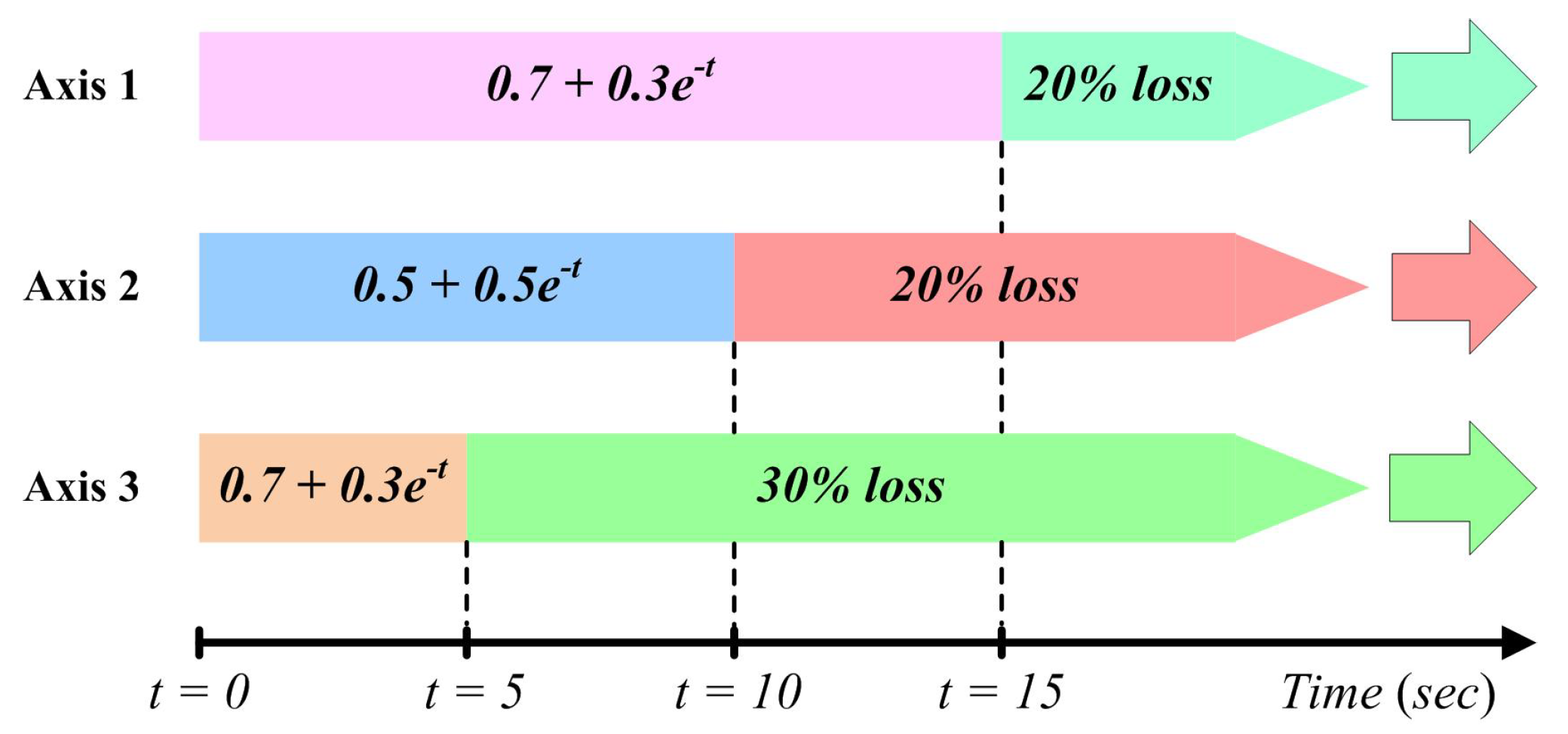
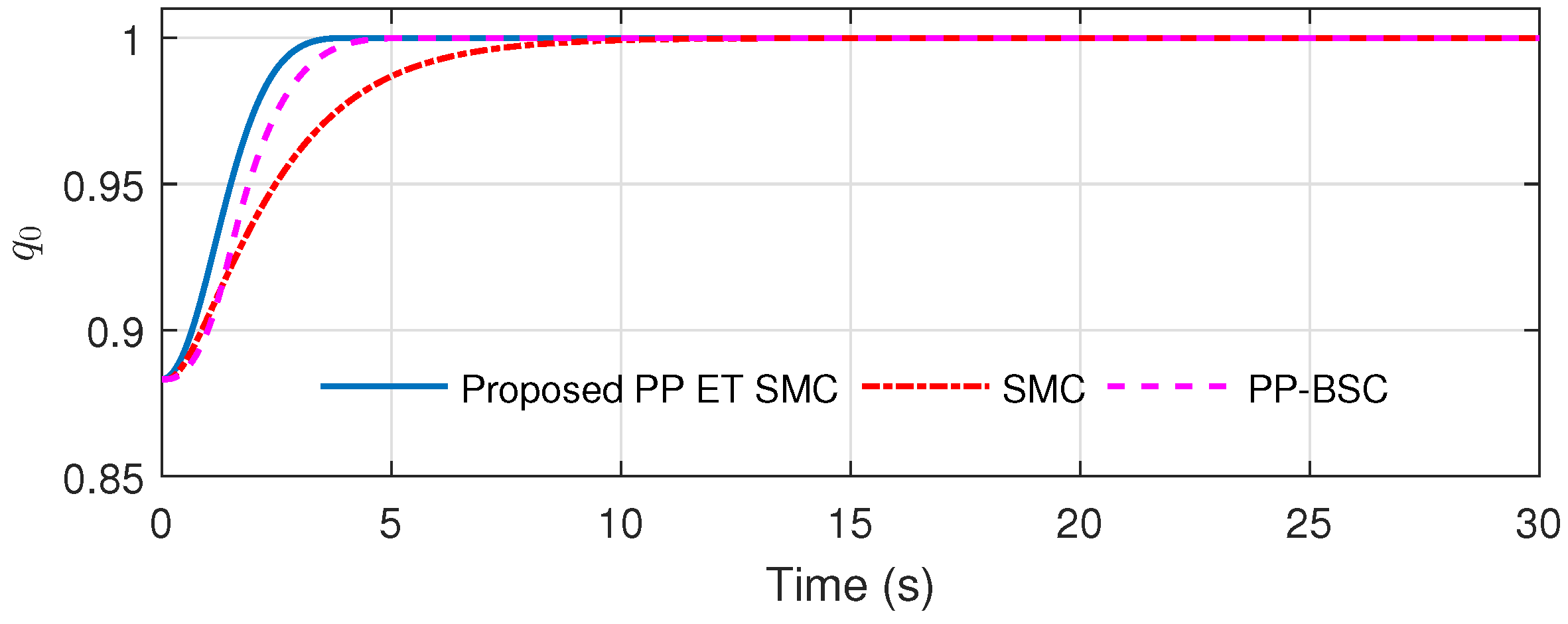
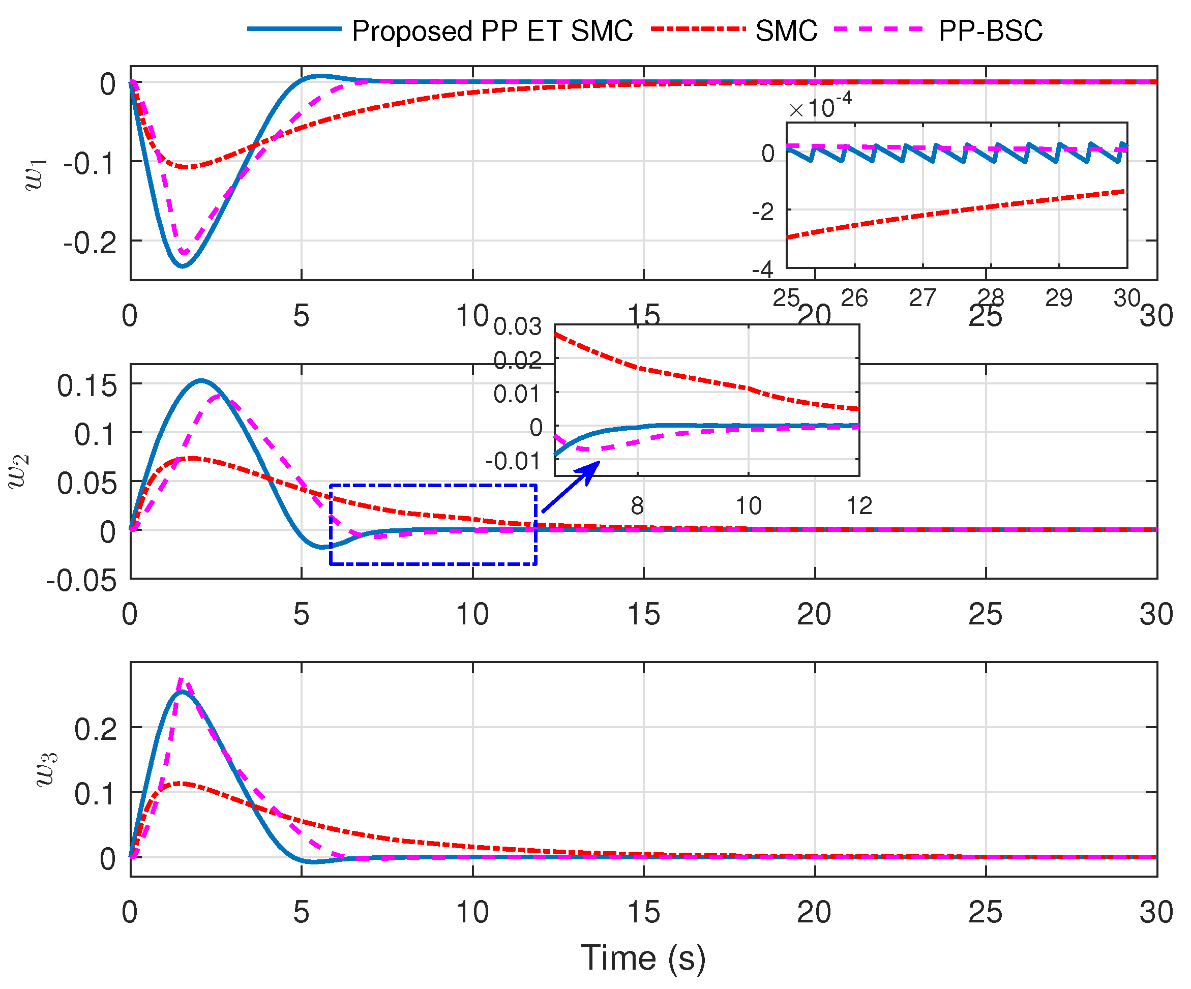
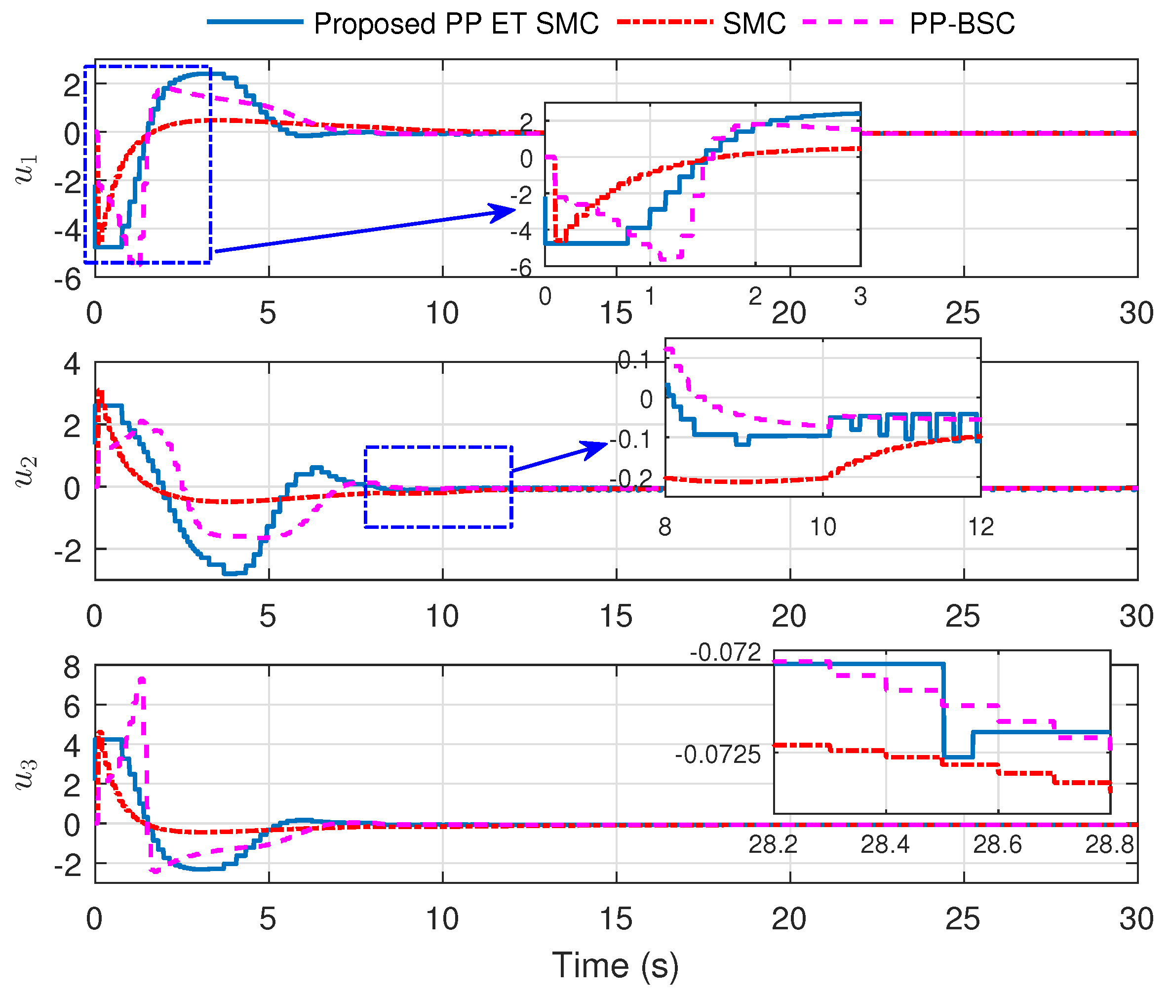
6. Numerical Analysis

This section presents the performance of attitude regulation of spacecraft under the proposed control strategy. The simulation results are also compared with two existing control schemes, i.e., the PPF based backstepping control [38] and the linear SMC without the PPF method [7]. The simulation analysis is carried out for the rigid spacecraft with the inertial matrices taken as
J 0 = 20 1.2 0.9 1.2 17 1.4 0.9 1.4 15 kg · m 2 , and Δ J = 10 % J 0 .
The external disturbance is considered as [29]
d 0 ( t ) = 1 + sin ( 0.4 t ) 1 + cos ( 0.5 t ) 1 0.8 cos ( 0.7 t ) × 10 3 N · m .
The additive faults E ( t ) in the actuators are taken as [55]
E ( t ) = 0.05 × 0.9 + 0.1 sin ( t / 10 ) 0.9 + 0.1 cos ( t / 15 ) 0.9 + 0.1 sin ( t / 20 ) , for t 8 s .
However, the multiplicative fault is illustrated in Figure 2 through the time-varying effectiveness parameter a i ( t ) with i = 1 , 2 , 3 for the individual actuator. It can be observe from Axis 1 response in Figure 2 that till 15 s its effectiveness decreases with a rate of 1 ( 0.7 + 0.3 exp t ) . Then, after t > 15 s, the actuator losses 20% of its effectiveness for all time. Similarly, the rest of the actuators’ effectiveness is also presented in Figure 2.
All the parameters of the proposed control methodology are given in Table 1. Further, the initial values of the system states are selected as
w ( 0 ) = 0 rad / s , and q ( 0 ) = [ 0.8832 0.3 0.2 0.3 ] T .

Simulation Results

Here, the results of the proposed prescribed performance-based ET SMC (PP-ET-SMC) strategy (47) is compared with linear SMC [7] and prescribed performance-based back-stepping control (PP-BSC) [38]. These two comparative approaches utilize the continuous periodic time update of the control scheme. Therefore, to respect the bandwidth constraint, these control schemes are updated at every period of 0.1s. Moreover, the desired apriori attitude response for the given problem is that it must be settled in the 30s, with no overshoot, and the steady-state response must be within the bound of 5 × 10 3 (or 1.74 × 10 2 rad in Euler angles). The overall system response of the above three control techniques is presented in Figure 3, Figure 4, Figure 5 and Figure 6. The scalar quaternion trajectory under the three schemes is shown in Figure 3. It is evident from the response of q 0 in Figure 3 that the proposed PP-ET-SMC has a faster convergence to + 1 than the other two approaches.
The attitude response of spacecraft under predefined constrained boundary (represented by the dotted green colored line) is shown in Figure 4. The vector quaternion response under PP-ET-SMC and PP-BSC is satisfactorily abiding by the abovementioned attitude constraint. The vector quaternion q v converges to the vicinity of zero within 30 s and without any over and undershoots. Further, the zoomed-in plot of Figure 4 during the steady-state also shows that q v 5 × 10 3 . On the other hand, the SMC scheme without PPF design [7] fails to respect the attitude constraint and crosses the PPF value, which can be seen in Figure 4. The state performance measures, such as settling time and steady-state convergence bound, are also tabulated in Table 2. Here, the settling time is calculated when the state converges and stays within the bound · 2 × 10 3 . As can be seen from Table 2 that the proposed scheme has a better settling time and convergence bound than the other two approaches. In fact, the SMC strategy of [7] fails to converge within the above bound in 30 s.
The angular velocity response under three control schemes is shown in Figure 5. Likewise the quaternion response, the proposed PP-ET-SMC scheme exhibits faster convergence and better steady-state performance than the other two comparative approaches. The transient and steady-state performance measures of w are also summarized in Table 2. It is obvious from the calculated values of performance measures in Table 2 that the proposed strategy is achieving better results than the schemes of [7,38].
The input torque responses of the control strategies are presented in Figure 6. Although the gain values of both the SMC schemes (i.e., (25) and [7]) are the same, the PPF strategy exerts more input torque to ensure the desired attitude response. It can be seen in Figure 6 that the PPF based control approaches (i.e., (25) and [38]) consumed more energy than the SMC scheme of [7]. Moreover, it is evident from the zoomed-in plots of Figure 6 that the proposed ET-based control updates the input value aperiodically. Further, between the two consecutive triggering sequences, the u ¯ ( t k ) value is kept at a fixed value. During the whole simulation run time of 30 s, the total number of updates (triggering instances) under the proposed PP-ET-SMC scheme is 153. On the other hand, the periodically sampled data techniques ([7,38]) with a period of 0.1 s updates 300 times. This shows that the proposed ET approach consumes low rate of data transfer than the continuous periodic time update schemes. Consequently, the proposed strategy also saves the communication data memory usage by 49% compared to the periodic approach. Thus, the PP-ET-SMC strategy reduces the communication burden on the spacecraft.
Figure 7a shows the inter-update time T of the proposed ET strategy. It is evident that T > 0 during the whole simulation, which also testifies the non-occurrence of Zeno phenomenon under the proposed ET mechanism. Moreover, Figure 7b presents the evolution of measurement error e ( t ) and the threshold function Γ . It can be observed from Figure 7b that whenever e ( t ) 2 reaches the time varying threshold value Γ 2 ( t ) , the ET input u ¯ c ( t k ) gets updated to the current value of u c ( t ) . As a result, the error value at that time of triggering instant becomes e ( t ) 2 = 0 , which is also visible in the zoomed-in plot of Figure 7b.
In view of the above comparative results, it is apparent that the proposed PP-ET-SMC scheme provides better system performance with a low rate of control data transfer through a restricted communication channel.

7. Conclusions

This paper presents a fault-tolerant attitude control of spacecraft under communication constraint using the event trigger-based sliding mode control method. The proposed controller also employs the prescribed performance function in its design to achieve a predefined desirable system response. The proposed scheme provides the invariable property against parametric uncertainties, external disturbances, and actuator faults. The theoretical results ensure the UUB convergence of all the internal and output signals using the Lyapunov analysis. Moreover, the absence of Zeno behavior is also guaranteed in the ET mechanism. Finally, the effectiveness of the proposed strategy is validated through numerical analysis. The comparative performance illustrates the efficacy of the proposed methodology under various performance measures. The potential future extension of this work could be along the lines of considering real-time actuator dynamics in the system or employing an adaptive-based attitude control with input delay.

Author Contributions

Conceptualization, S.M.A.; methodology, S.M.A.; software, S.M.A.; validation, S.M.A. and A.K.; formal analysis, S.M.A.; investigation, S.M.A. and A.K.; resources, M.N. and A.A.; data curation, S.M.A.; writing—original draft preparation, S.M.A.; writing—review and editing, S.M.A. and A.K.; visualization, S.M.A. and A.K.; supervision, M.N.; funding acquisition, A.A. All authors have read and agreed to the published version of the manuscript.

Funding

The APC was funded by Qassim University, Buraydah, Saudi Arabia.

Conflicts of Interest

The authors declare no conflict of interest.

References

  1. Wertz, J.R. Spacecraft Attitude Determination and Control; Springer Science & Business Media: Berlin/Heidelberg, Germany, 2012; Volume 73. [Google Scholar]
  2. Vadali, S.R. Variable-structure control of spacecraft large-angle maneuvers. J. Guid. Control. Dyn. 1986, 9, 235–239. [Google Scholar] [CrossRef]
  3. Utkin, V.; Guldner, J.; Shijun, M. Sliding Mode Control in Electro-Mechanical Systems; CRC Press: Boca Raton, FL, USA, 1999; Volume 34. [Google Scholar]
  4. McDuffie, J.; Shtessel, Y.; McDuffie, J.; Shtessel, Y. A sliding mode controller and observer for satellite attitude control. In Proceedings of the Guidance, Navigation, and Control Conference, New Orleans, LA, USA, 11–13 August 1997; p. 3755. [Google Scholar]
  5. Massey, T.; Shtessel, Y. Continuous traditional and high-order sliding modes for satellite formation control. J. Guid. Control. Dyn. 2005, 28, 826–831. [Google Scholar] [CrossRef]
  6. Luo, W.; Chu, Y.C.; Ling, K.V. H-infinity inverse optimal attitude-tracking control of rigid spacecraft. J. Guid. Control Dyn. 2005, 28, 481–494. [Google Scholar] [CrossRef]
  7. Zhu, Z.; Xia, Y.; Fu, M. Adaptive sliding mode control for attitude stabilization with actuator saturation. IEEE Trans. Ind. Electron. 2011, 58, 4898–4907. [Google Scholar] [CrossRef]
  8. Xia, Y.; Zhu, Z.; Fu, M.; Wang, S. Attitude tracking of rigid spacecraft with bounded disturbances. IEEE Trans. Ind. Electr. 2011, 58, 647–659. [Google Scholar] [CrossRef]
  9. Sun, L.; Zheng, Z. Disturbance-observer-based robust backstepping attitude stabilization of spacecraft under input saturation and measurement uncertainty. IEEE Trans. Ind. Electr. 2017, 64, 7994–8002. [Google Scholar] [CrossRef]
  10. Amrr, S.M.; Nabi, M.; Tiwari, P.M. A fault-tolerant attitude tracking control of spacecraft using an anti-unwinding robust nonlinear disturbance observer. Proc. Inst. Mech. Eng. Part G J. Aerosp. Eng. 2019, 233, 6005–6018. [Google Scholar] [CrossRef]
  11. Amrr, S.M.; Nabi, M. Finite-time fault tolerant attitude tracking control of spacecraft using robust nonlinear disturbance observer with anti-unwinding approach. Adv. Space Res. 2020, 66, 1659–1671. [Google Scholar] [CrossRef]
  12. Lyke, J.C. Plug-and-play satellites. IEEE Spectr. 2012, 49, 36–42. [Google Scholar] [CrossRef]
  13. Viel, C.; Bertrand, S.; Kieffer, M.; Piet-Lahanier, H. Distributed event-triggered control for multi-agent formation stabilization. IFAC-PapersOnLine 2017, 50, 8025–8030. [Google Scholar] [CrossRef]
  14. Wu, B. Spacecraft attitude control with input quantization. J. Guid. Control Dyn. 2015, 39, 176–181. [Google Scholar] [CrossRef]
  15. Wu, B.; Cao, X. Robust attitude tracking control for spacecraft with quantized torques. IEEE Trans. Aerosp. Electron. Syst. 2017, 54, 1020–1028. [Google Scholar] [CrossRef]
  16. Gao, H.; Lv, Y.; Nguang, S.K.; Ma, G. Finite-time attitude quantised control for rigid spacecraft. Int. J. Syst. Sci. 2018, 49, 2328–2340. [Google Scholar] [CrossRef]
  17. Amrr, S.M.; Srivastava, J.P.; Nabi, M. Robust Attitude Stabilization of Spacecraft under Constrained Network with Hysteresis Quantizer. IEEE J. Miniaturization Air Space Syst. 2020. [Google Scholar] [CrossRef]
  18. Amrr, S.M.; Nabi, M.; Srivastava, J.P. Quantized Attitude Control of Rigid Spacecraft without Unwinding. IFAC-PapersOnLine 2020, 53, 105–110. [Google Scholar] [CrossRef]
  19. Tallapragada, P.; Chopra, N. On event triggered tracking for nonlinear systems. IEEE Trans. Autom. Control 2013, 58, 2343–2348. [Google Scholar] [CrossRef] [Green Version]
  20. Guerrero-Castellanos, J.; Vega-Alonzo, A.; Durand, S.; Marchand, N.; Gonzalez-Diaz, V.R.; Castañeda-Camacho, J.; Guerrero-Sánchez, W.F. Leader-following consensus and formation control of VTOL-UAVs with event-triggered communications. Sensors 2019, 19, 5498. [Google Scholar] [CrossRef] [PubMed] [Green Version]
  21. Cucuzzella, M.; Incremona, G.P.; Ferrara, A. Event-triggered variable structure control. Int. J. Control 2020, 93, 252–260. [Google Scholar] [CrossRef] [Green Version]
  22. Nowzari, C.; Garcia, E.; Cortés, J. Event-triggered communication and control of networked systems for multi-agent consensus. Automatica 2019, 105, 1–27. [Google Scholar] [CrossRef] [Green Version]
  23. Incremona, G.P.; Ferrara, A. Adaptive model-based event-triggered sliding mode control. Int. J. Adapt. Control Signal Process. 2016, 30, 1298–1316. [Google Scholar] [CrossRef]
  24. Al Issa, S.; Chakravarty, A.; Kar, I. Improved event-triggered adaptive control of non-linear uncertain networked systems. IET Control Theory Appl. 2019, 13, 2146–2152. [Google Scholar] [CrossRef]
  25. Al Issa, S.; Kar, I. Event-triggered adaptive control of uncertain non-linear systems under input delay and limited resources. Int. J. Dyn. Control 2021. [Google Scholar] [CrossRef]
  26. Postoyan, R.; Tabuada, P.; Nešić, D.; Anta, A. A framework for the event-triggered stabilization of nonlinear systems. IEEE Trans. Autom. Control 2015, 60, 982–996. [Google Scholar] [CrossRef] [Green Version]
  27. Abdelrahim, M.; Postoyan, R.; Daafouz, J.; Nešić, D. Robust event-triggered output feedback controllers for nonlinear systems. Automatica 2017, 75, 96–108. [Google Scholar] [CrossRef] [Green Version]
  28. Xing, L.; Wen, C.; Liu, Z.; Su, H.; Cai, J. Event-triggered adaptive control for a class of uncertain nonlinear systems. IEEE Trans. Autom. Control. 2016, 62, 2071–2076. [Google Scholar] [CrossRef]
  29. Wu, B.; Shen, Q.; Cao, X. Event-triggered attitude control of spacecraft. Adv. Space Res. 2018, 61, 927–934. [Google Scholar] [CrossRef]
  30. Amrr, S.M.; Banerjee, A.; Nabi, M. Robust attitude control of rigid spacecraft based on event-triggered approach with anti-unwinding. In Proceedings of the IEEE 2019 Fifth Indian Control Conference (ICC), New Delhi, India, 9–11 January 2019; pp. 510–515. [Google Scholar]
  31. Amrr, S.M.; Nabi, M. Attitude Stabilization of Flexible Spacecraft under Limited Communication with Reinforced Robustness. Trans. Inst. Meas. Control 2019, 41, 4475–4487. [Google Scholar] [CrossRef]
  32. Amrr, S.M.; Nabi, M.; Iqbal, A. An Event-Triggered Robust Attitude Control of Flexible Spacecraft with Modified Rodrigues Parameters under Limited Communication. IEEE Access 2019, 7, 93198–93211. [Google Scholar] [CrossRef]
  33. Chenliang, W.; Yun, L.; Qinglei, H.; Huang, J. Event-triggered adaptive control for attitude tracking of spacecraft. Chin. J. Aeronaut. 2019, 32, 454–462. [Google Scholar]
  34. Xing, L.; Zhang, J.; Liu, C.; Zhang, X. Fuzzy-logic-based adaptive event-triggered sliding mode control for spacecraft attitude tracking. Aerosp. Sci. Technol. 2021, 108, 106394. [Google Scholar] [CrossRef]
  35. Ning, K.; Wu, B.; Xu, C. Event-triggered adaptive fuzzy attitude takeover control of spacecraft. Adv. Space Res. 2020, 67, 1761–1772. [Google Scholar] [CrossRef]
  36. Bechlioulis, C.P.; Rovithakis, G.A. Robust adaptive control of feedback linearizable MIMO nonlinear systems with prescribed performance. IEEE Trans. Autom. Control 2008, 53, 2090–2099. [Google Scholar] [CrossRef]
  37. Hu, Q.; Shao, X.; Guo, L. Adaptive fault-tolerant attitude tracking control of spacecraft with prescribed performance. IEEE/ASME Trans. Mechatron. 2018, 23, 331–341. [Google Scholar] [CrossRef]
  38. Zhang, C.; Ma, G.; Sun, Y.; Li, C. Simple model-free attitude control design for flexible spacecraft with prescribed performance. Proc. Inst. Mech. Eng. Part G J. Aerosp. Eng. 2019, 233, 2760–2771. [Google Scholar] [CrossRef]
  39. Wei, C.; Chen, Q.; Liu, J.; Yin, Z.; Luo, J. An overview of prescribed performance control and its application to spacecraft attitude system. Proc. Inst. Mech. Eng. Part I J. Syst. Control. Eng. 2020, 235, 435–447. [Google Scholar] [CrossRef]
  40. Wu, X.; Luo, S.; Wei, C.; Liao, Y. Observer-based fault-tolerant attitude tracking control for rigid spacecraft with actuator saturation and faults. Acta Astronaut. 2021, 178, 824–834. [Google Scholar] [CrossRef]
  41. Wang, C.; Lei, G.; Hu, Q.; Qiao, J. Event-triggered adaptive attitude tracking control for spacecraft with unknown actuator faults. IEEE Trans. Ind. Electron. 2020, 67, 2241–2250. [Google Scholar] [CrossRef]
  42. Wie, B.; Weiss, H.; Arapostathis, A. Quarternion feedback regulator for spacecraft eigenaxis rotations. J. Guid. Control. Dyn. 1989, 12, 375–380. [Google Scholar] [CrossRef]
  43. Amrr, S.M.; Banerjee, A.; Nabi, M. Fault-Tolerant Attitude Control of Small Spacecraft using Robust Artificial Time Delay Approach. IEEE J. Miniaturization Air Space Syst. 2020, 1, 179–187. [Google Scholar] [CrossRef]
  44. Hu, Q.; Xiao, B.; Wang, D.; Poh, E.K. Attitude control of spacecraft with actuator uncertainty. J. Guid. Control Dyn. 2013, 36, 1771–1776. [Google Scholar] [CrossRef]
  45. Cai, W.; Liao, X.; Song, Y. Indirect robust adaptive fault-tolerant control for attitude tracking of spacecraft. J. Guid. Control. Dyn. 2008, 31, 1456–1463. [Google Scholar] [CrossRef]
  46. Jia, Z.; Hu, Z.; Zhang, W. Adaptive output-feedback control with prescribed performance for trajectory tracking of underactuated surface vessels. ISA Trans. 2019, 95, 18–26. [Google Scholar] [CrossRef] [PubMed]
  47. Karayiannidis, Y.; Doulgeri, Z. Model-free robot joint position regulation and tracking with prescribed performance guarantees. Robot. Auton. Syst. 2012, 60, 214–226. [Google Scholar] [CrossRef]
  48. Wei, C.; Luo, J.; Dai, H.; Bian, Z.; Yuan, J. Learning-based adaptive prescribed performance control of postcapture space robot-target combination without inertia identifications. Acta Astronaut. 2018, 146, 228–242. [Google Scholar] [CrossRef]
  49. Sontag, E.D. Mathematical Control Theory: Deterministic Finite Dimensional Systems; Springer Science & Business Media: Berlin/Heidelberg, Germany, 2013; Volume 6. [Google Scholar]
  50. Mei, J.; Ren, W.; Ma, G. Distributed coordination for second-order multi-agent systems with nonlinear dynamics using only relative position measurements. Automatica 2013, 49, 1419–1427. [Google Scholar] [CrossRef]
  51. Yu, S.; Yu, X.; Shirinzadeh, B.; Man, Z. Continuous finite-time control for robotic manipulators with terminal sliding mode. Automatica 2005, 41, 1957–1964. [Google Scholar] [CrossRef]
  52. Al Issa, S.; Kar, I. Design and implementation of event-triggered adaptive controller for commercial mobile robots subject to input delays and limited communications. Control Eng. Pract. 2021, 114, 104865. [Google Scholar] [CrossRef]
  53. Ha, Q.P.; Nguyen, Q.; Rye, D.C.; Durrant-Whyte, H.F. Fuzzy sliding-mode controllers with applications. IEEE Trans. Ind. Electr. 2001, 48, 38–46. [Google Scholar] [CrossRef]
  54. Krstic, M.; Kokotovic, P.V.; Kanellakopoulos, I. Nonlinear & Adaptive Control Design, 1st ed.; John Wiley & Sons: Hoboken, NJ, USA, 1995. [Google Scholar]
  55. Hu, Q.; Shi, Y.; Shao, X. Adaptive fault-tolerant attitude control for satellite reorientation under input saturation. Aerosp. Sci. Technol. 2018, 78, 171–182. [Google Scholar] [CrossRef]
Figure 1. Schematics of the proposed PPF based ET SMC.
Electronics 10 01709 g001
Figure 2. Multiplicative fault in the actuator.
Electronics 10 01709 g002
Figure 3. Scalar quaternion response.
Electronics 10 01709 g003
Figure 4. Quaternion response.
Electronics 10 01709 g004
Figure 5. Angular velocity response.
Electronics 10 01709 g005
Figure 6. Control input response.
Electronics 10 01709 g006
Figure 7. (a) The inter-update time response ( T ) of the proposed ET scheme, (b) the time evolution of e 2 and Γ 2 .
Electronics 10 01709 g007
Table 1. Parameters of the proposed scheme with i = 1 , 2 , 3 .
Para.ValuePara.ValuePara.ValuePara.Value
i 0.5 ξ ¯ i 1 k 1 2 γ 0.001
ϱ i 0 0.5 ξ ̲ i 1 k 2 0.2
ϱ i 0.005 β 0.15 θ 0.3
Table 2. Performance measures under different schemes.
Controllers →Proposed (47)SMC [7]PP BSC [38]
T settling of e v (s)6.6649.9510.48
T settling of w (s)7.2954.819.01
Convg. set of e v 0.18  × 10 3 7.0  × 10 3 1.3  × 10 3
Convg. set of w 4.4  × 10 5 1.7  × 10 4 2.7  × 10 5
No. of updates153300300
% of data usage51%100%100%
Publisher’s Note: MDPI stays neutral with regard to jurisdictional claims in published maps and institutional affiliations.

