
Multi-Kernel Polar Codes versus Classical Designs with Different Rate-Matching Approaches †

Abstract
:1. Introduction
2. Polarization Circuits
2.1. Kernel Circuit
2.2. Kernel Circuit
2.3. Multi-Kernel Circuit
3. Resizing Polar Codes
3.1. Puncturing
3.2. Shortening
4. Analysis of Optimal Design Techniques
- A circuit of kernel size 2;
- A circuit of kernel size 3;
- Multi-kernel circuit composed of and circuits;
- Puncturing;
- Shortening.
4.1. Error Rate Performance
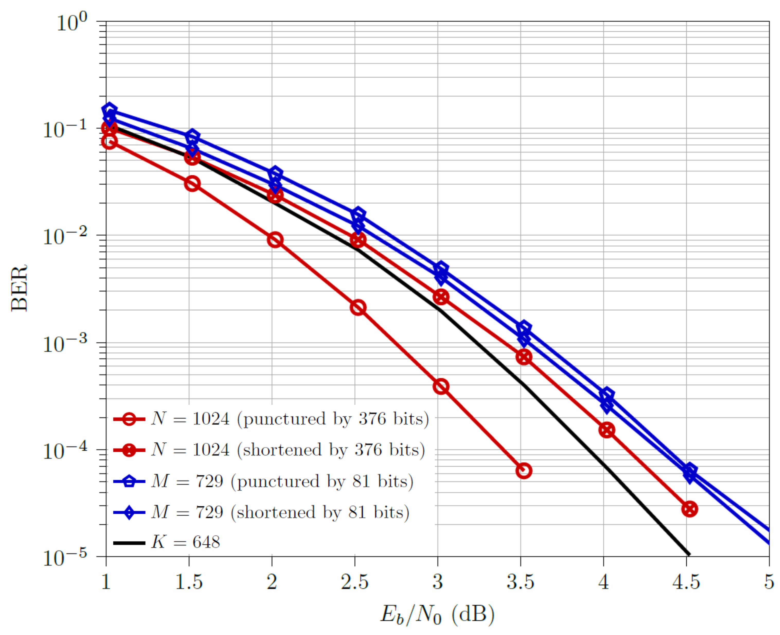
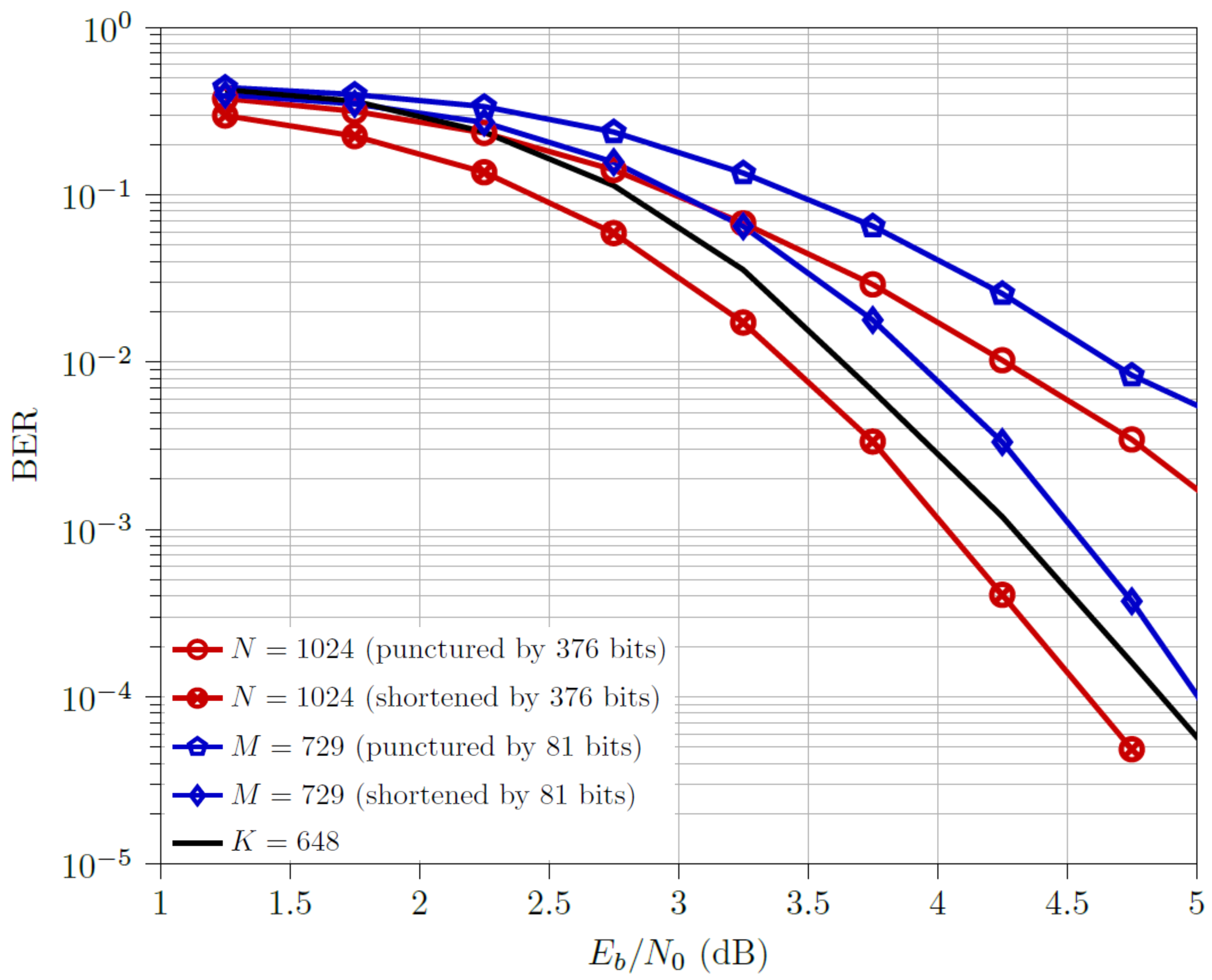
4.1.1. Scenario 1
- For the low code rate, , punctured codewords outperform the shortened ones. The multi-kernel codewords outperform all but punctured codewords, with a dB difference. One interesting observation is w.r.t. downsized codewords. Although at low , one would expect the punctured ones to be better than the shortened ones, the performance difference is marginal with shortened ones narrowly outperforming the punctured ones. This corresponds to the observations made in [3], where shortened codewords outperform the punctured ones even at low code rates.
- For the half code rate, , shortened and codewords outperform the respective punctured ones. The multi-kernel codewords outperform nearly all but shortened , with just a dB difference.
- For the high code rate, , shortened and codewords outperform the respective punctured ones. The multi-kernel codewords outperform all but shortened codewords, with just a dB difference.
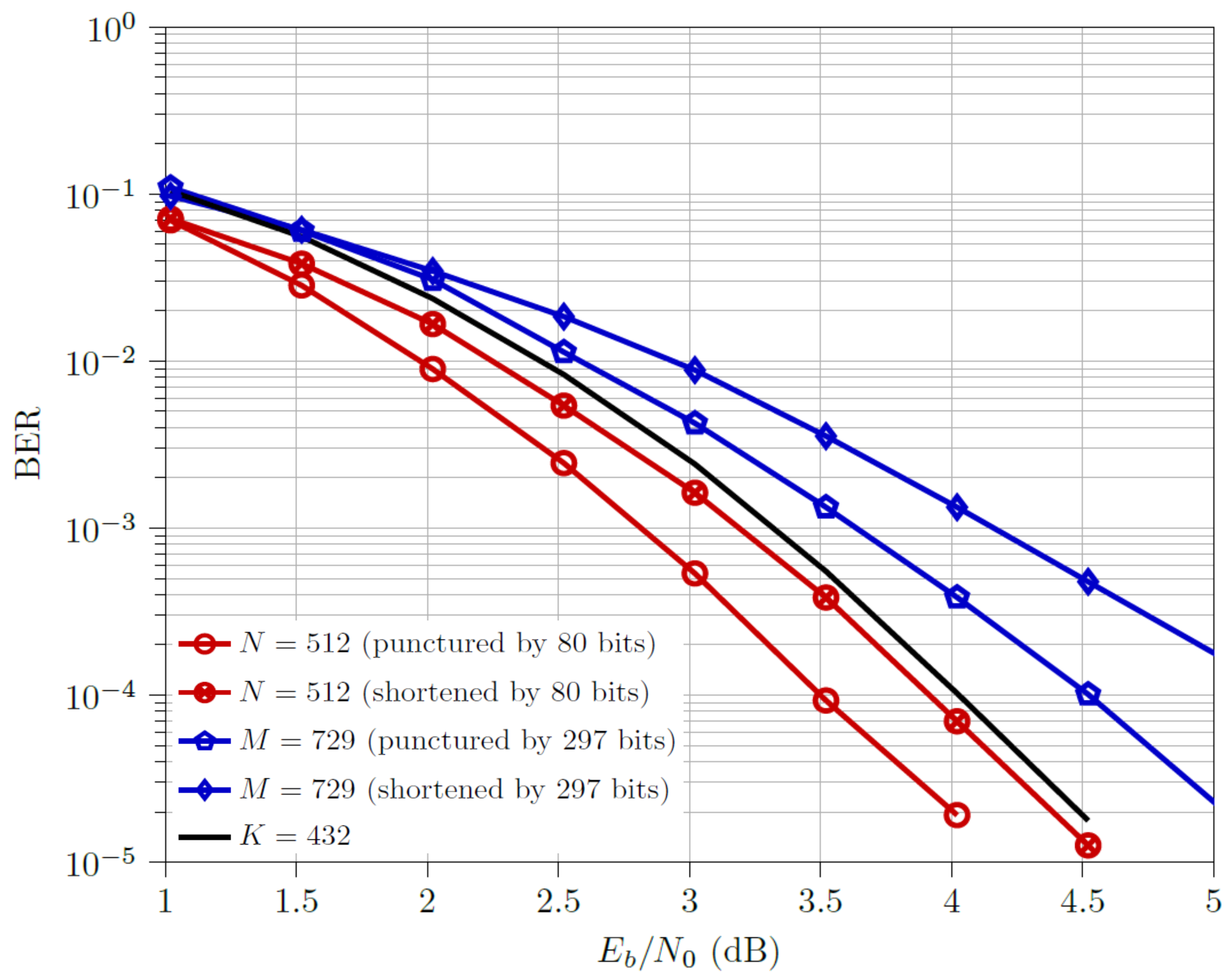
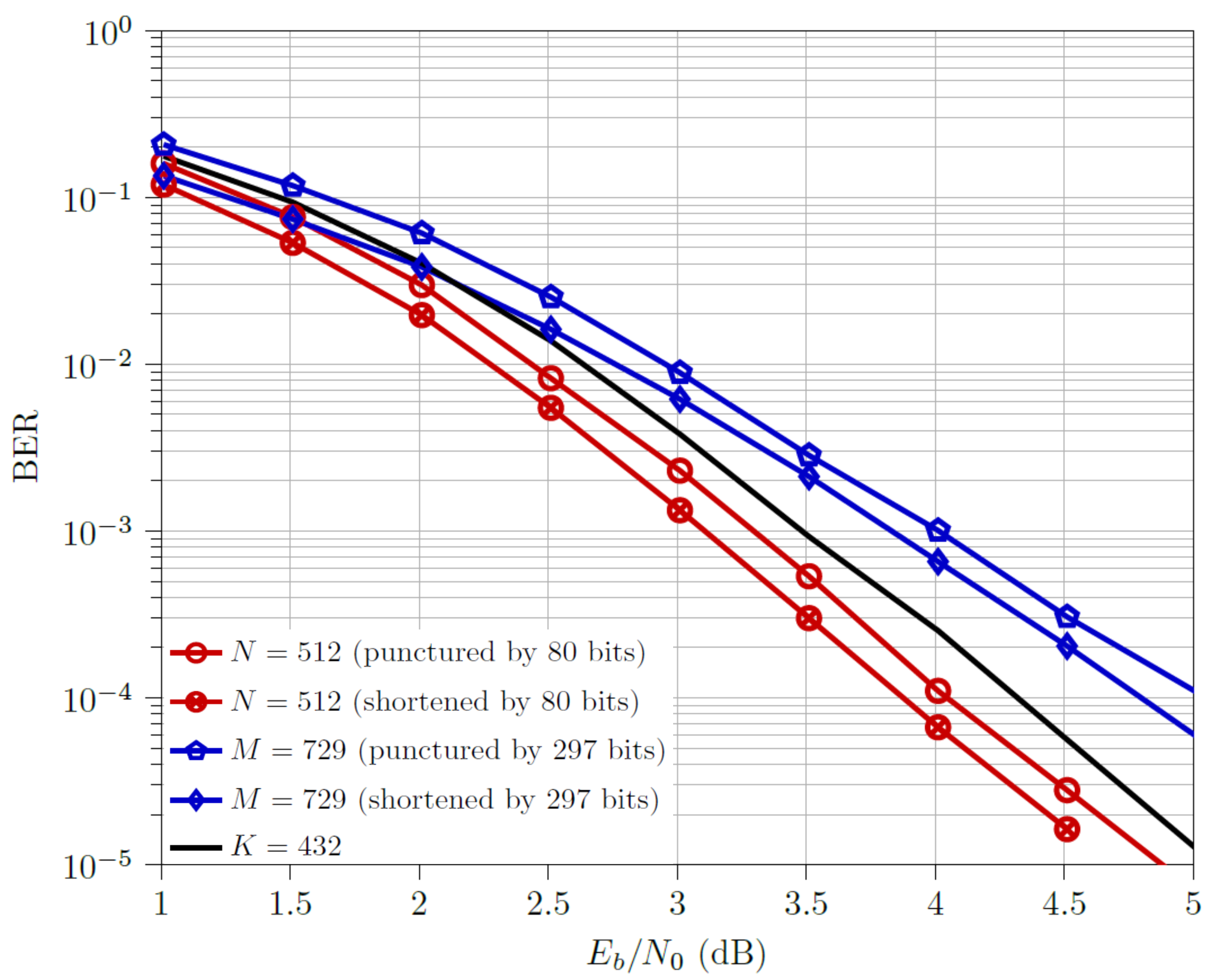
4.1.2. Scenario 2
- For the low code rate, , punctured and codewords outperform the corresponding shortened ones. This phenomenon of punctured M being better than their shortened counterparts had not been observed in any plots of [3]. Note that here, downsizing of codewords was carried out by 297 bits, whereas in [3], downsizing was performed by 217 bits, indicating that a higher number of downsized bits improves the prediction of using code rate value for determining optimal downsizing technique, as observed in Scenario 1 as well. The multi-kernel codewords outperform both the downsized codewords but are outperformed by both the downsized codewords, with a performance gap of ≈0.5 dB from the optimal design (i.e., punctured codewords).
- For the half code rate, , shortened and codewords outperform the respective punctured ones. The multi-kernel codewords outperform both the downsized codewords but are outperformed by both the downsized codewords, with a performance gap of ≈0.5 dB from the optimal design (i.e., shortened codewords).
- For the high code rate, , shortened and codewords outperform the respective punctured ones. The multi-kernel codewords outperform all but the shortened codewords, with a ≈0.3 dB difference.
4.2. Computational Complexity
4.3. Assessment
5. Future Work
6. Conclusions
Author Contributions
Funding
Conflicts of Interest
Abbreviations
| AWGNC | Additive White Gaussian Noise Channel |
| BEC | Binary Erasure Channel |
| BER | Bit-Error Rate |
| BPSK | Binary Phase Shift Keying |
| DE | Density Evolution |
| DTS | Downsizing Type Selection |
| LLR | Log-Likelihood Ratio |
| QoS | Quality of Service |
| SC | Successive Cancellation |
References
- Bioglio, V.; Condo, C.; Land, I. Design of Polar Codes in 5G New Radio. IEEE Commun. Surv. Tutor. 2020, 23, 29–40. [Google Scholar] [CrossRef] [Green Version]
- 3GPP TS 38.212 V16.5.0. Technical Specification, 3rd Generation Partnership Project; Technical Specification Group Radio Access Network; NR; Multiplexing and Channel Coding (Release 16). 2021. Available online: https://www.3gpp.org/ftp/Specs/archive/\38_series/38.212/ (accessed on 28 May 2021).
- Saha, S.; Adrat, M. Versatile Polar Codes with different Kernel Sizes and Rate Matching approaches. In Proceedings of the 14th International Conference on Signal Processing and Communication Systems (ICSPCS), Adelaide, SA, Australia, 14–16 December 2020; pp. 1–7. [Google Scholar]
- Gabry, F.; Bioglio, V.; Land, I.; Belfiore, J. Multi-kernel construction of polar codes. In Proceedings of the IEEE International Conference on Communication (ICC), Paris, France, 21–25 May 2017; pp. 761–765. [Google Scholar]
- Benammar, M.; Bioglio, V.; Gabry, F.; Land, I. Multi-Kernel Polar Codes: Proof of Polarization and Error Exponents. In Proceedings of the IEEE Information Theory Workshop (ITW), Kaohsiung, Taiwan, 6–10 November 2017; pp. 101–105. [Google Scholar]
- Bioglio, V.; Gabry, F.; Land, I.; Belfiore, J. Minimum-Distance Based Construction of Multi-Kernel Polar Codes. In Proceedings of the IEEE Global Communications Conference (GLOBECOM), Singapore, 4–8 December 2017; pp. 1–6. [Google Scholar]
- Bioglio, V.; Land, I.; Gabry, F.; Belfiore, J. Flexible design of Multi-Kernel Polar Codes by reliability and distance properties. In Proceedings of the IEEE 10th International Symposium on Turbo Codes and Iterative Information Processing (ISTC), Hong Kong, China, 3–7 December 2018; pp. 1–5. [Google Scholar]
- Bioglio, V.; Land, I. On the Marginalization of Polarizing Kernels. In Proceedings of the IEEE 10th International Symposium on Turbo Codes and Iterative Information Processing (ISTC), Hong Kong, China, 3–7 December 2018; pp. 1–5. [Google Scholar]
- Bioglio, V.; Land, I.; Condo, C. Improved Hybrid Design of Polar Codes and Multi-Kernel Polar Codes. In Proceedings of the IEEE International Symposium on Information Theory (ISIT), Paris, France, 7–12 July 2019; pp. 1947–1951. [Google Scholar]
- Bioglio, V.; Gabry, F.; Land, I.; Belfiore, J. Multi-Kernel Polar Codes: Concept and Design Principles. IEEE Trans. Commun. 2020, 68, 5350–5362. [Google Scholar] [CrossRef]
- Arikan, E. Channel Polarization: A Method for Constructing Capacity-Achieving Codes for Symmetric Binary-Input Memoryless Channels. IEEE Trans. Inf. Theory 2009, 55, 3051–3073. [Google Scholar] [CrossRef]
- Mahdavifar, H.; El-Khamy, M.; Lee, J.; Kang, I. Polar Coding for Bit-Interleaved Coded Modulation. IEEE Trans. Veh. Technol. 2016, 65, 3115–3127. [Google Scholar] [CrossRef]
- Zhang, L.; Zhang, Z.; Wang, X. Polar code with block-length N = 3n. In Proceedings of the International Conference on Wireless Communications and Signal Processing (WCSP), Huangshan, China, 25–27 October 2012; pp. 1–6. [Google Scholar]
- Cheng, L.; Zhou, W.; Zhang, L. Hybrid Multi-Kernel Construction of Polar Codes. In Proceedings of the IEEE 89th Vehicular Technology Conference (VTC2019-Spring), Kuala Lumpur, Malaysia, 28 April–1 May 2019; pp. 1–5. [Google Scholar]
- Xia, C.; Tsui, C.-Y.; Fan, Y. Construction of Multi-Kernel Polar Codes With Kernel Substitution. IEEE Wirel. Commun. Lett. 2020, 9, 1879–1883. [Google Scholar] [CrossRef]
- Mori, R.; Tanaka, T. Performance of Polar Codes with the Construction using Density Evolution. IEEE Commun. Lett. 2009, 13, 519–521. [Google Scholar] [CrossRef]
- Mori, R.; Tanaka, T. Performance and construction of polar codes on symmetric binary-input memoryless channels. In Proceedings of the IEEE International Symposium on Information Theory (ISIT), Seoul, Korea, 28 June–4 July 2009; pp. 1496–1500. [Google Scholar]
- Hassani, S.; Mori, R.; Tanaka, T.; Urbanke, R. Rate-Dependent Analysis of the Asymptotic Behavior of Channel Polarization. IEEE Trans. Inf. Theory 2013, 59, 2267–2276. [Google Scholar] [CrossRef] [Green Version]
- Gabry, F.; Bioglio, V.; Land, I. Low-Complexity Puncturing and Shortening of Polar Codes. In Proceedings of the IEEE Wireless Communications and Networking Conference Workshops (WCNCW), San Franciso, CA, USA, 19–22 March 2017; pp. 1–6. [Google Scholar]
- Wang, R.; Liu, R. A Novel Puncturing Scheme for Polar Codes. IEEE Commun. Lett. 2014, 18, 2081–2084. [Google Scholar] [CrossRef]
- Zhang, L.; Zhang, Z.; Wang, X.; Yu, Q.; Chen, Y. On the puncturing patterns for punctured polar codes. In Proceedings of the IEEE International Symposium on Information Theory (ISIT), Honolulu, HI, USA, 30 June–5 July 2014; pp. 121–125. [Google Scholar]
- Miloslavskaya, V. Shortened Polar Codes. IEEE Trans. Inf. Theory 2015, 61, 4852–4865. [Google Scholar] [CrossRef]
- Vangala, H.; Viterbo, E.; Hong, Y. A Comparitive Study of Polar Codes Constructions for the AWGN Channel. arXiv 2015, arXiv:1501.02473v1. [Google Scholar]
- Saha, S.; Adrat, M. Novel Multi-Parameter based Rate-Matching of Polar Codes. In Proceedings of the International Conference on Military Communications and Information Systems (ICMCIS), Oeiras, Portugal, 4–5 May 2021. [Google Scholar]
- Tal, I.; Vardy, A. List Decoding of Polar Codes. IEEE Trans. Inf. Theory 2015, 61, 2213–2226. [Google Scholar] [CrossRef]
- Afisiadis, O.; Balatsoukas-Stimming, A.; Burg, A. A low-complexity improved successive cancellation decoder for polar codes. In Proceedings of the 48th Asilomar Conference on Signals, Systems and Computers, Pacific Grove, CA, USA, 2–5 November 2014; pp. 2116–2120. [Google Scholar]
- Stark, M.; Shah, A.; Bauch, G. Polar code construction using the information bottleneck method. In Proceedings of the IEEE Wireless Communications and Networking Conference Workshops (WCNCW), Barcelona, Spain, 15–18 April 2018; pp. 7–12. [Google Scholar]
- Ebada, M.; Cammerer, S.; Elkelesh, A.; ten Brink, S. Deep Learning-based Polar Code Design. arXiv 2019, arXiv:1909.12035v2. [Google Scholar]
- Romano, G.; Ciuonzo, D. Minimum-Variance Importance-Sampling Bernoulli Estimator for Fast Simulation of Linear Block Codes over Binary Symmetric Channels. IEEE Trans. Wirel. Commun. 2014, 13, 486–496. [Google Scholar] [CrossRef]
- Romano, G.; Drago, A.; Ciuonzo, D. Sub-optimal importance sampling for fast simulation of linear block codes over BSC channels. In Proceedings of the 8th International Symposium on Wireless Communication Systems, Aachen, Germany, 6–9 November 2011; pp. 141–145. [Google Scholar]


| Scenario 1 | Scenario 2 | |||||
|---|---|---|---|---|---|---|
| Encoding/Decoding length | 1024 | 729 | 648 | 512 | 729 | 432 |
| Number of downsized bits | 376 | 81 | 0 | 80 | 297 | 0 |
| Z | ||||||
| Modulation Scheme | BPSK | BPSK | ||||
| Coderates | {, , } | {, , } | ||||
| Scenario 1 | Scenario 2 | |||||
|---|---|---|---|---|---|---|
| Encoding/Decoding length | 1024 | 729 | 648 | 512 | 729 | 432 |
| Number of downsized bits | 376 | 81 | 0 | 80 | 297 | 0 |
| Complexity units | 5120 | 2916 | 2700 | 2304 | 2916 | 1728 |
| Punctured N | Shortened N | K | Punctured M | Shortened M | |
|---|---|---|---|---|---|
| BER at | − | 0 | |||
| BER at | 0 | + | 0 | 0 | |
| BER at | + | 0 | − | ||
| Complexity | 0 | − | |||
| Punctured N | Shortened N | K | Punctured M | Shortened M | |
|---|---|---|---|---|---|
| BER at | + | 0 | |||
| BER at | + | 0 | − | ||
| BER at | − | + | 0 | 0 | |
| Complexity | − | 0 | |||
Publisher’s Note: MDPI stays neutral with regard to jurisdictional claims in published maps and institutional affiliations. |
© 2021 by the authors. Licensee MDPI, Basel, Switzerland. This article is an open access article distributed under the terms and conditions of the Creative Commons Attribution (CC BY) license (https://creativecommons.org/licenses/by/4.0/).
Share and Cite
Saha, S.; Adrat, M. Multi-Kernel Polar Codes versus Classical Designs with Different Rate-Matching Approaches. Electronics 2021, 10, 1717. https://doi.org/10.3390/electronics10141717
Saha S, Adrat M. Multi-Kernel Polar Codes versus Classical Designs with Different Rate-Matching Approaches. Electronics. 2021; 10(14):1717. https://doi.org/10.3390/electronics10141717
Chicago/Turabian StyleSaha, Souradip, and Marc Adrat. 2021. "Multi-Kernel Polar Codes versus Classical Designs with Different Rate-Matching Approaches" Electronics 10, no. 14: 1717. https://doi.org/10.3390/electronics10141717