Abstract
A desire to produce power in microgrids has grown as the demand for electricity has expanded and the cost of installing modern transmission lines over long distances has become infeasible. As such, microgrids pose DC/AC harmonic distortion losses to the voltage supply that eventually fluctuate the output voltage. The key takeaways that this study presents are: (a) a configuration for microgrids integrated to the national grid using back-to-back converters in a renewable power system is achieved; (b) different scenarios of various schemes of sustainability of the power management in microgrids are analyzed; and (c) the reliable and stable network output power distribution is achieved. In this, the proposed control configuration provides space for construction and stability of the power system with sustainability of the power management. The results show that this current configuration works and stabilizes the network in the shortest time possible, and that the DC connection voltage is regulated and maintains reliable network output despite declining slope controllers, DC power and voltage, and power electronic back-to-back converters. Overall, the simulation results show that the proposed system shows acceptable performance under different scenarios. The accuracy of the results is validated with mathematical formulation simulation using MATLAB software. This system can be utilized in distant regions where there is no power grid or in areas where, despite having a power infrastructure, renewable energies are used to supply the output load for the majority of the day and night.
1. Introduction
Rising fuel prices, environmental problems, decreasing fossil fuel reserves, and the growth of new energy generation technologies have led to the need of sustainable energy distributed generation (DG) resources in today’s renewable power systems. Recently, there has been an increase of electric vehicles charging stations and their integration to smart grid systems that has improved the voltage quality and harmonic distortion losses [1,2]. At present, most of the power required by the national grid is provided by large power plants [3,4]. These power plants are often located in remote a location, which leads to an increase of power transmission losses; hence, there is a requirement for the construction of new transmission systems. Distributed generation sources such as photovoltaic systems, wind turbines, fuel cells and battery storage systems are among the main sources currently in use [5,6,7,8]. Unlike large power plants, these distributed generation resources are utilized at low capacities and used in domestic dimensions [9,10]. As distributed generation sources are close to loads, power transmission losses are decreased, and the need for additional transmission lines and substations is reduced [11,12].
At present, due to the growth of the use of distributed generation resources, the use of microgrids to manage and control the power generated and released into the national grid has become a paramount need [13,14]. Mass control of distributed generation sources in a microgrid requires precise design of control systems so that the voltage and frequency are controlled and that the load is adequately supplied by distributed generation sources so that none of the sources are overloaded. The quality of power supply has become increasingly critical as the number of sensitive electronic loads has increased, such as those linked to the grid through thyristor and inverter rectifiers. The power generated by the global grid has harmonic distortion losses and as such a negative influence on voltage quality leading to the sudden voltage drops impacting distribution networks [15,16]. As a result, back-to-back converters are used to link today’s microgrids to the upstream grid. In particular, these converters are used as microgrid isolator of the national grid. With these converters, the desired sustainable power quality is provided for the microgrids. However, the microgrid controllability is complicated and the integrated control of distributed generation sources and the back-to-back converter becomes a challenge.
A microgrid structure is introduced in [17] that consists of new energy sources, in which resources are able to work in two modes: connected to the grid and insular. The methods of power distribution in the microgrid are investigated in [18]. In this, the central and decentralized methods of microgrid control are introduced. According to [19], power generation sources are classified into three categories of forming, feeding and supporting sources according to their role in the microgrid. The work in [20] discussed the design of internal control systems for intermediate converters of distributed generation sources in which, the control methods in the dq field as well as the static device are introduced. Paper [21] reviewed the design methods of voltage, current, power of inverter controllers and the design method in the frequency field for inverter. The parallel performance of inverter-based distributed generation sources has been investigated in [22,23]. It showed decentralized methods and the decentralized control method of power distribution called droop. Droop control is a technique for mimicking the sagging of a conventional generator set. When several communication line-free inverters are linked in parallel, this control technique is commonly used. According to [24], storage capacity and two-way power exchange in energy storage sources along with new energy sources have been used in order to balance the microgrid power. It showed energy storage sources control of voltage and frequency. The works in [25,26] introduced new energy-storage combined systems.
The prior work by Ghosh and Joshi (2000) [27] presented static compensator by using symmetrical components to develop an algorithm to compute three phase reference currents. More recently, the prior work by Majumder et al. (2009) [28] discussed back-to-back converters in two modes only whilst the limitation of not considering the dynamic power flows. Our work is progressing the state of the art by this paper, with the contribution being a sustainable energy distribution configuration for microgrids integrated to the national grid using back-to-back converters in a renewable power system. The power control scheme is presented for controlling the microgrid’s voltage and frequency while adhering to the aforementioned constraints. Distributed control services systems are implemented for this purpose, and a suitable back-to-back inverter control system is demonstrated to enable two-way power exchange at dynamic range and analyzed at various scenarios. A method of power sharing between resources can be used in this situation, in the case of insular areas where there is no national grid. As a result, in the case of grid-connected systems, the position of the back-to-back converter is investigated in this paper. In this investigation, the microgrid is required to supply part of its power through a back-to-back converter and receive the remainder from available sources under normal conditions. However, there may be times when using this template is not the best option. The simulations conducted in the MATLAB/Simulink software are used to test the output of the control system implemented in this article, and the simulation results are used to validate the proposed process. However, if the distributed generation sources are unable to generate the maximum power output, it is important to automatically change the power of the distributed generation to its full power. As a result, an alternate system must be used in which the power control should be used instead of power delivery. With these converters, the quality of the micro grid makes it difficult to control the micro grid, however, and the integrated control of the manufacturer’s production resources and the back-to-back converter can become a challenge. For this purpose, it is necessary to introduce a control system for the micro grids, in which, without the need to use telecommunication systems, there can be control of the voltage and frequency of payment and the desired ability in the court delivery network. In this case, it is necessary to control the voltage and frequency in the form of the partnership created by all sources and the limitations of electricity generation to accumulate in the sources of the producer.
2. Materials and Methods
2.1. Microgrid
A micro grid usually consists of different loads and resources that are operated as controllable and stand-alone systems as they can be disconnected and connected with high reliability, either on-grid or off-grid. Micro sources are classified into high frequency AC and DC categories. These two micro source categories are compared with different applications of renewable energy based power systems such as PV modules, fuel cells, wind or micro turbines and reciprocating engines. Figure 1 shows a standard microgrid schematic that is supplied from different sources.
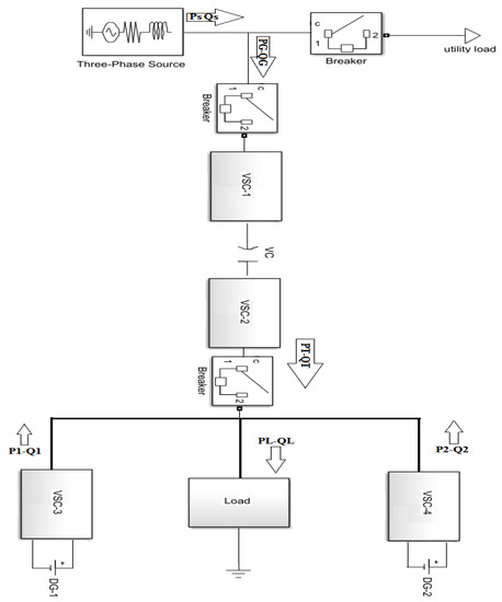
Figure 1.
A schematic of microgrids, converters and micro sources [28].
2.2. Back to Back Controlled Converter
In the back-to-back converter, there are two VSCs (Voltage Source Converters). In this structure there are two three-phase H bridges that are connected through a common DC link [27]. It should be noted that the filter structure in each VSC depends on the system requirements and control of the converters, the IGBTs (Insulated Gate Bipolar Junction Transistor) used in this structure are shown as controllable switches. The structure of the VSC converter is shown in Figure 2, and the DG1 (Distributed Generator) is assumed to be the ideal DC voltage source.
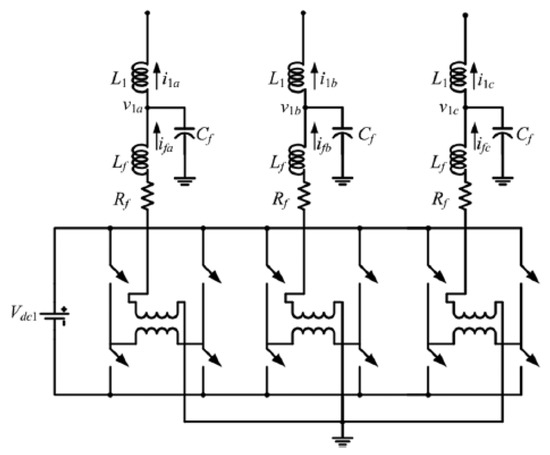
Figure 2.
A schematic diagram of Voltage Source Converter (VSC) structure [28].
The VSC output voltage is calculated using Equations (1) and (2).
In this case, it fills any power gaps, and DGs provide their full usable power through back-to-back converters if necessary. The value of voltage and reference angle VSC-2 can be written as shown in Equations (1) and (2).
The reference output of DGs is different from the reference output of back-to-back converters. The control strategy is the same for both DGs and hence, only the DG-1 reference generation is discussed here. As the output impedance of DG sources is inductive, inputting active and reactive power from the source into the microgrid can be controlled by changing the voltage and angle. Figure 3 shows the power flow from the DG-1 to the microgrid.
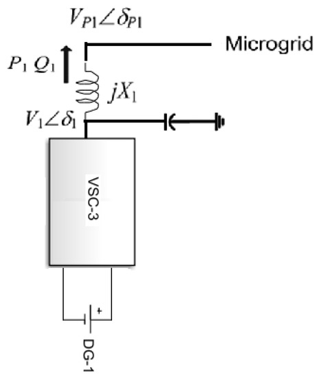
Figure 3.
Power distribution from DG to microgrid.
The complex power (both active and reactive powers) from DG to microgrid are calculated by using Equations (5) and (6).
Hence, to control the transfer of P and/or Q, one of the four variables in the equation should be changed. As shown earlier, the phase values and the voltage range generated can be controlled by the microgrid governor, respectively. However, from a power transmission point of view, generator control is slow and inefficient because it imposes a limit on power transmission at the steady-state operating point. Due to this, the power angle δ in the equation must be kept small to avoid large disturbances and maintain transfer stability relatively large demand for reactive power that unnecessarily overloads generation and transmission systems. The voltage and voltage angle are expressed in Equations (7) and (8).
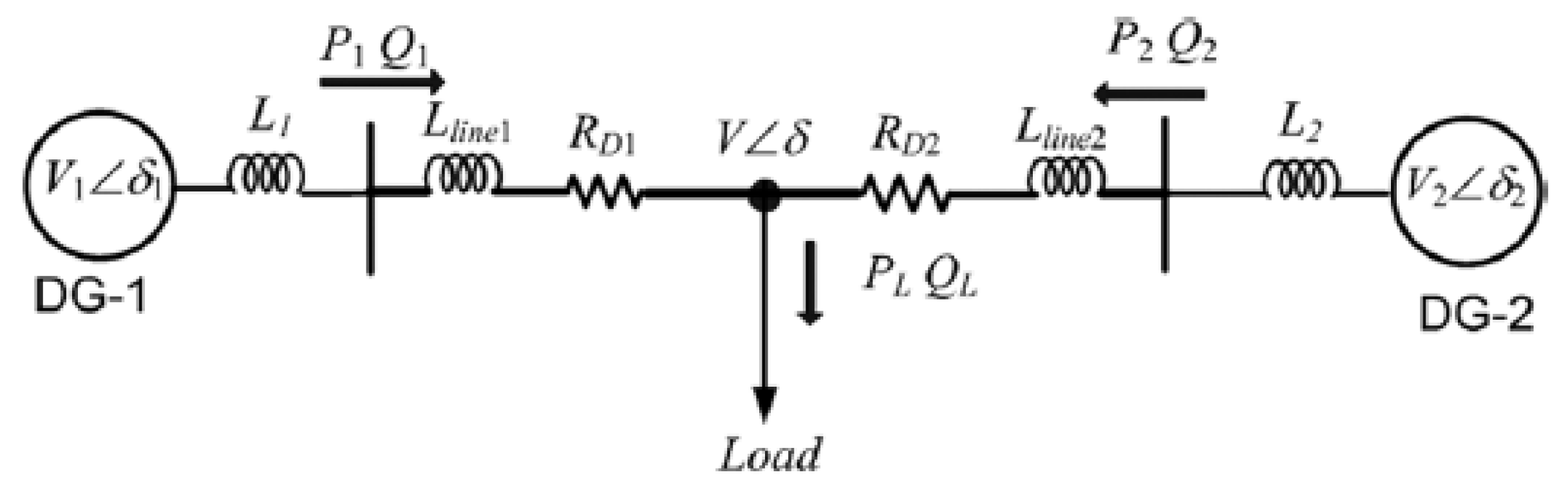
The complex voltage in polar form (magnitude and angle) from DG-1 is the outcome of when a load is applied to it and to show the power distribution with angle drop, two DGs and a load are considered as in Figure 4.
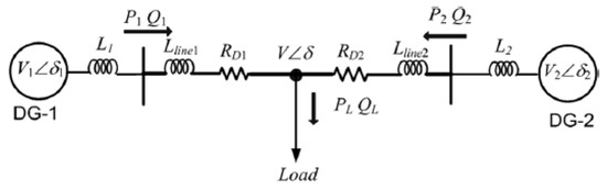
Figure 4.
Power distribution between DGs [28].
Voltage angle relations are calculated using Equations (9) and (10).
where, X1 and X2 are expressed as according to Equations (11) and (12).
The reactance of the lines calculated using Equations (13) and (14).
Using the above equations, the complex angles can be written as shown in Equations (15)–(21).
Equations (22) and (23) can be used to distribute power between two generation units.
2.3. DC Microgrid Method of Control
DC–DC converters are electrical circuits that have lower energy losses during transmission between different circuits as well as converters used to convert DC voltage [28,29]. The current of DC distributed generation sources with constant power control is obtained through Equation (24).
For the slope control performance, the reference current is obtained according to Equation (25).
Distributed DC sources that have storage and can be controlled according to the output power or small sudden changes in the requested power.
2.4. AC Microgrid Method of Control
It is worth noting that the DGs in the AC microgrid are ideal DC sources [28,29]. The reference current is calculated using the following equations.
The reference voltage is calculated using Equations (30) and (31).
The equations for voltage and angle adjustment are calculated as Equations (32) and (33).
2.5. Simulation of the Studied System
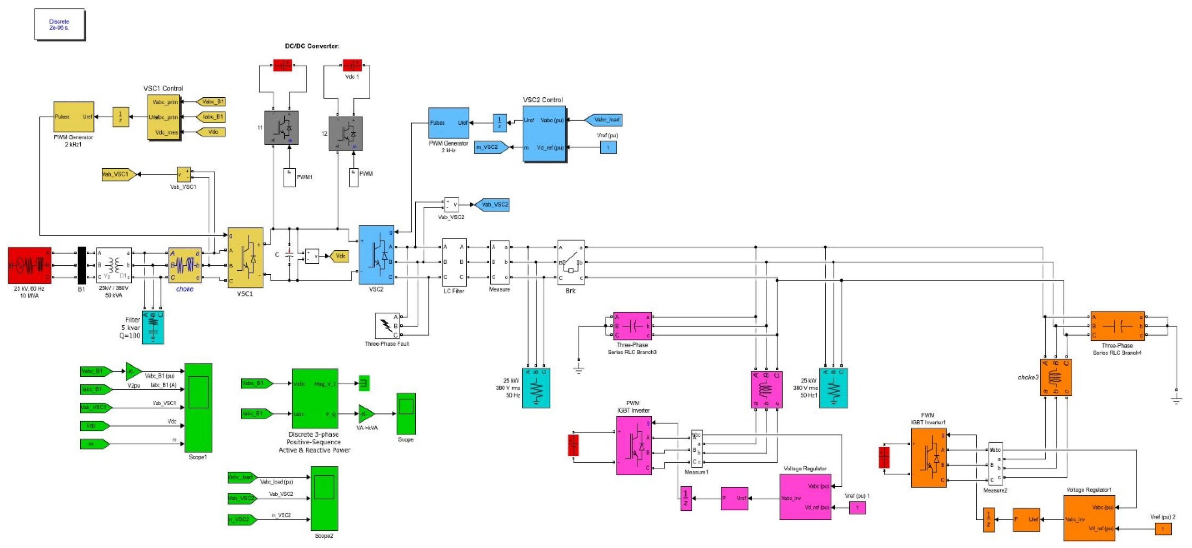
The outline model of the simulated system in the software is shown in Figure 5. The information of this model is given in Table 1.

Figure 5.
Studied simulation system.

Table 1.
Information of the studied system (load and microgrid).
In this design, back-to-back converters are created from two VSC 2- VSC1 with a common DC link. AC micro grids are connected to the system with 2 DG sources and once. Manufacturers of connectors connected to VSCs (AC) convert the output voltage of the DGs to AC in the micro grid. They are connected to the system via a DC/DC converter. DC/DC output voltage converter, DG increases the voltage level by increasing the DC. The back-to back connects to the mains and the mains at a point. Both VSC 1-VSC-2 converters are pressurized by a common capacitive DC bus with voltage if you assume that at the distribution level, the micro grid has deep resistive lines shown as a filter.
3. Results and Discussion
3.1. Scenario 1: Normal System Operation When AC Microgrid Receives Continuous Power from the National Grid and Vice-Versa
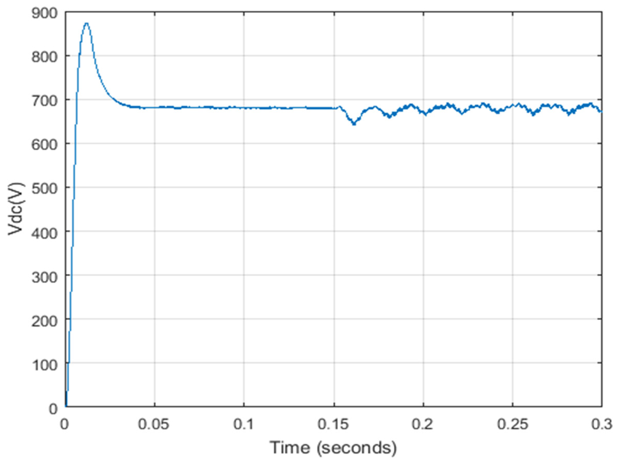
Figure 6 shows the DC voltage and Figure 7 shows the common point voltage between the national grid and microgrid. There is no disruption in the DC base voltage and the common connection point voltage, as seen in these Figures. For instance, after 0.15 s, if the microgrid is connected to the system, the DC voltage will be slightly disturbed and shows the performance of a stable system.
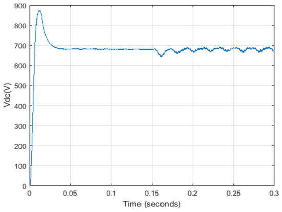
Figure 6.
DC voltage in scenario 1.
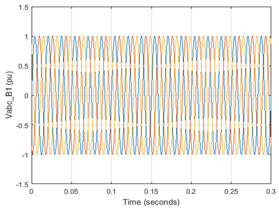
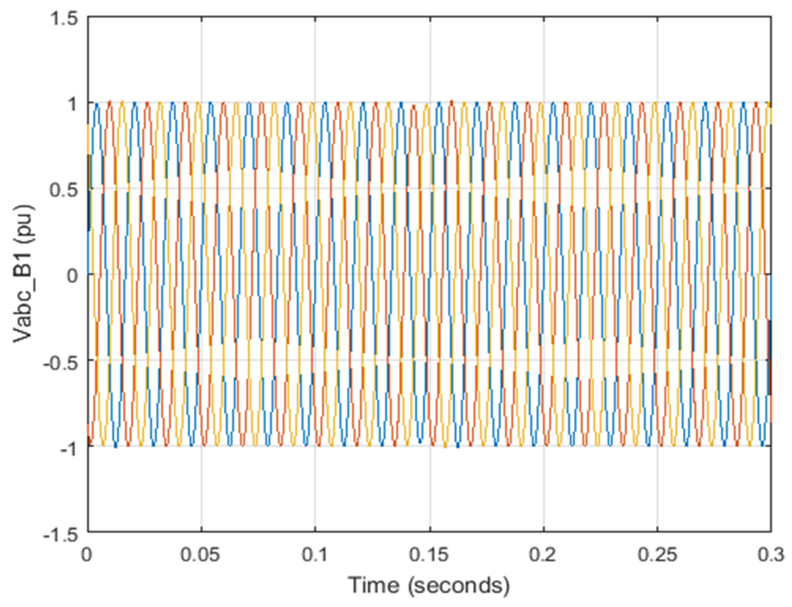
Figure 7.
Common point voltage between the grid and microgrid.
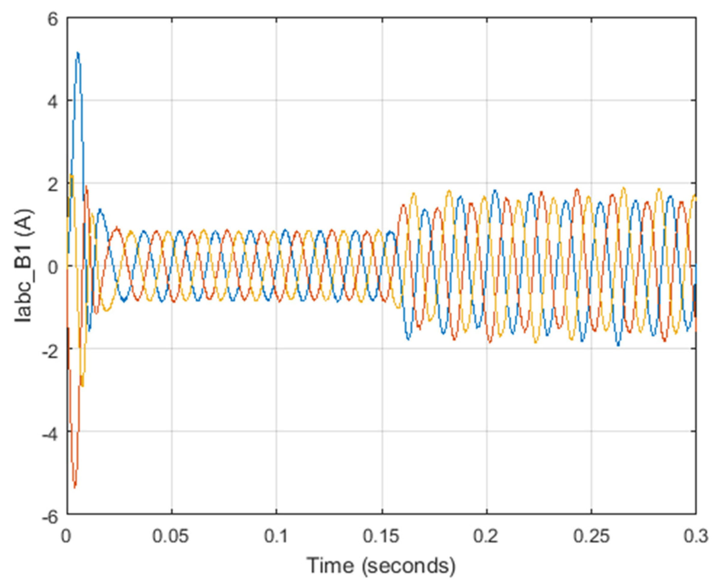
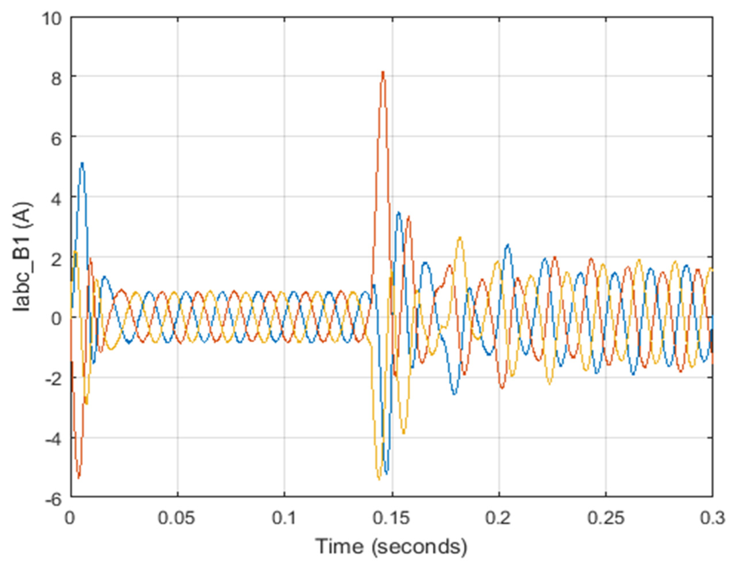
Figure 8 shows the current of the common point (common base) of the grid and the microgrid, which has increased after the instantaneous time of 0.15 s.

Figure 8.
Common point (common base) grid and microgrid current.
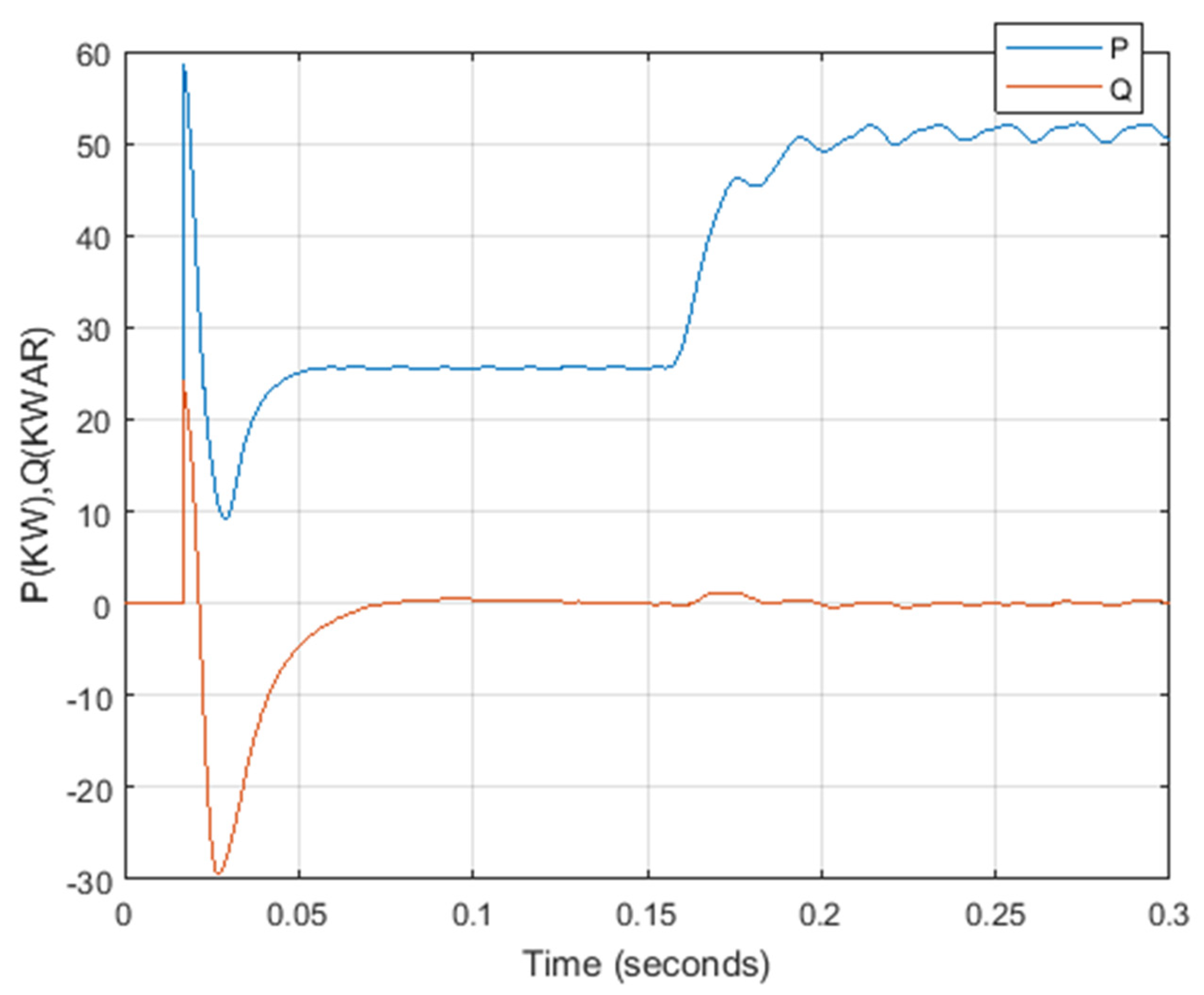
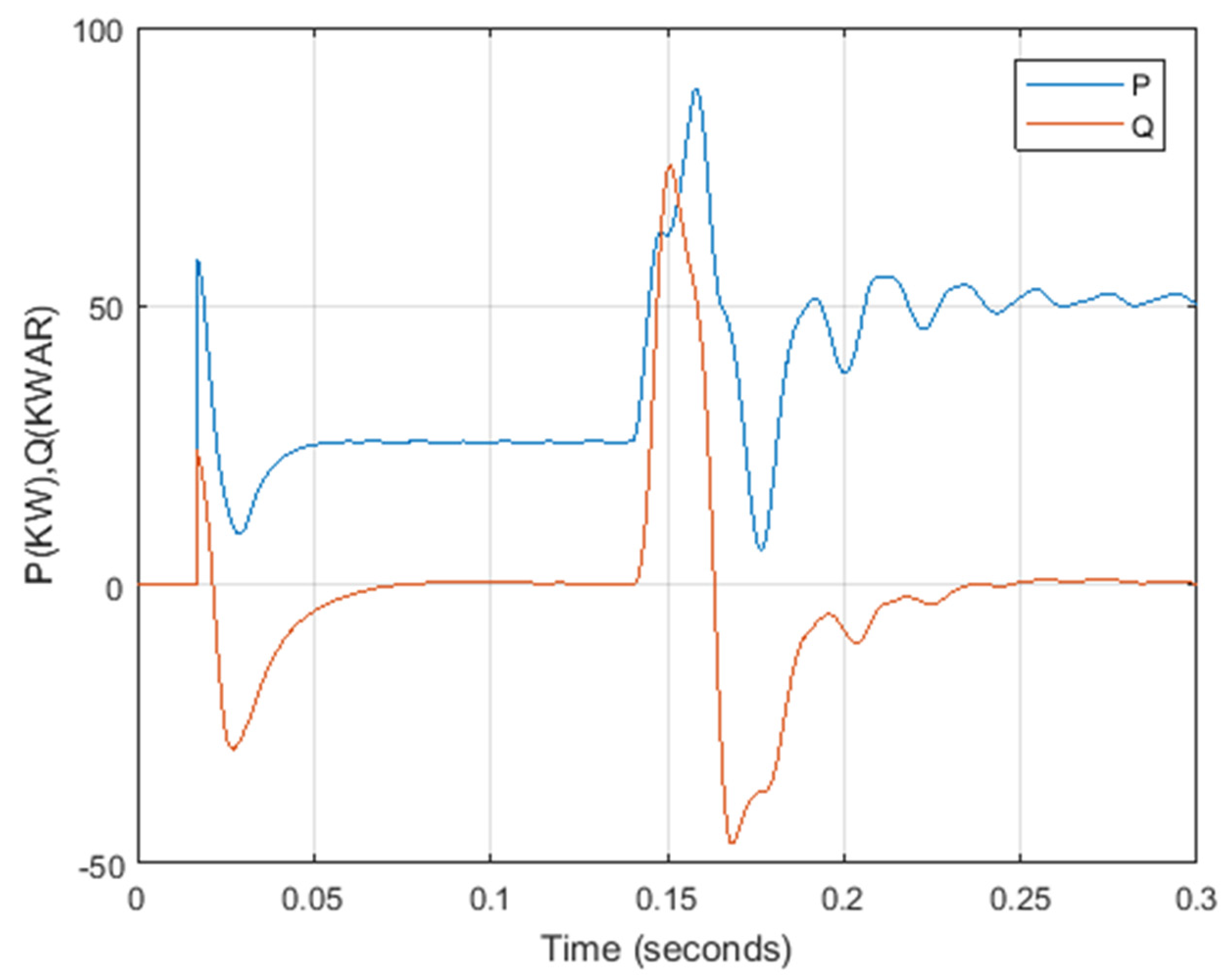
For this purpose, distributed generation resources control systems are introduced and a suitable control system for back-to-back inverter is designed to allow two-way power exchange. In the case of insular mode, where there is no national grid, a method of dividing power between resources can be used. However, in the case of on-grid, it is necessary to examine the role of the back-to-back converter. Under normal circumstances, the microgrid is expected to supply part of its power through a back-to-back converter and take the rest of the power from available sources. However, circumstances may arise in which the use of this method is inappropriate. For example, when the load power increases and the power of the distributed generation sources reaches the maximum allowable value, these sources can no longer control the voltage and frequency, so it is necessary in this case, the working condition of the back-to-back converter is changed and provide the required load power that cannot be provided by distributed generation sources. Active and reactive power distribution is also shown in Figure 9. In this figure, the active and reactive power are denoted by P and Q, respectively. As can be seen, before the moment of adding the microgrid, the power distribution is less than in the case of adding the microgrid.

Figure 9.
Active and reactive power distribution.
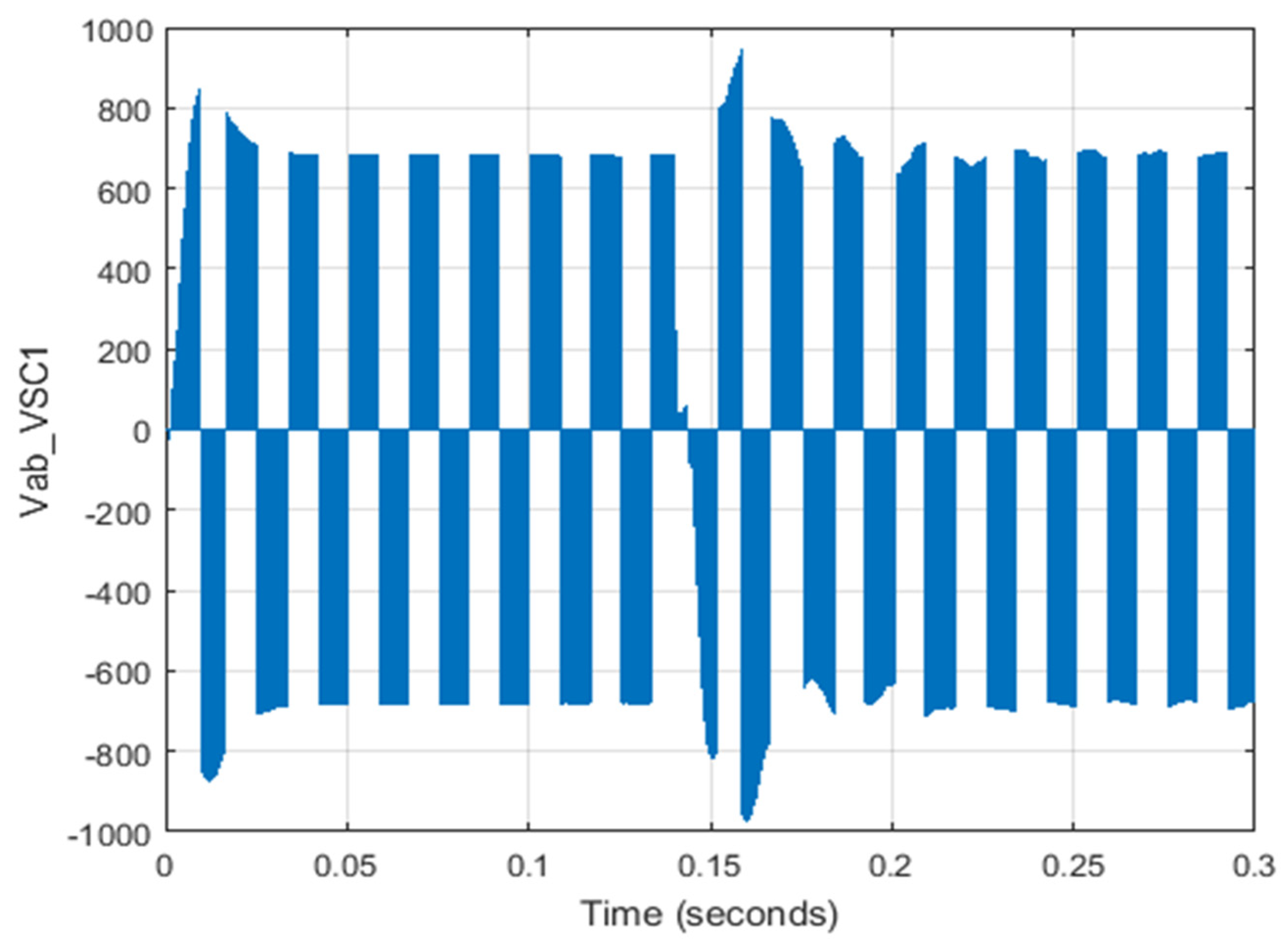
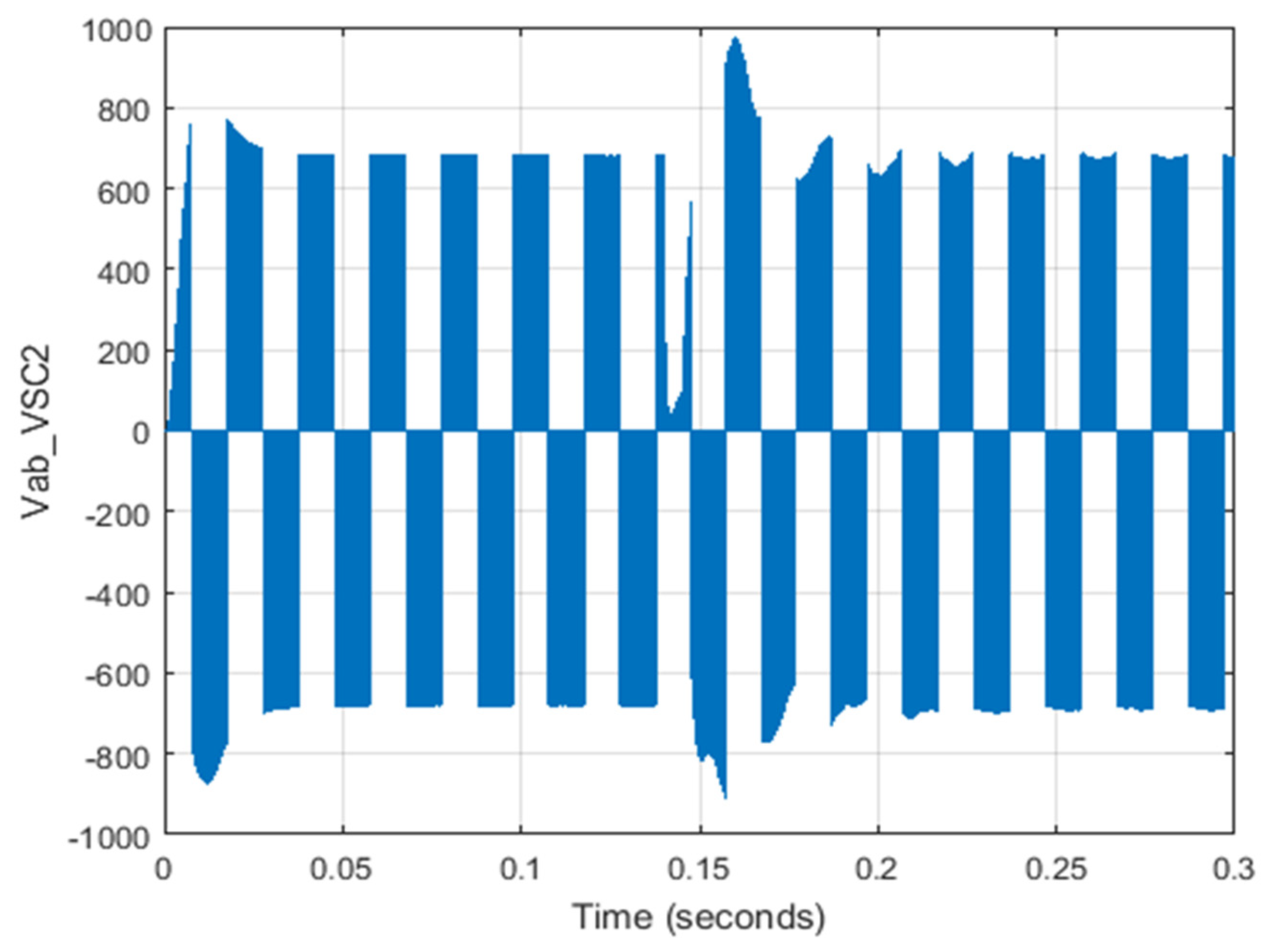
The two-phase voltage ab for each two converters is also shown in Figure 10 and Figure 11. Their changes are also noticeable at the moment 0.15 s.
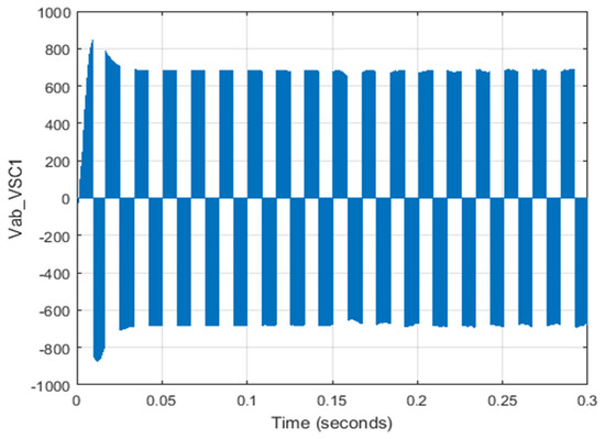
Figure 10.
Two-phase voltage ab for VSC-1.
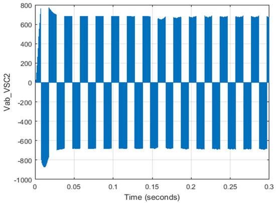
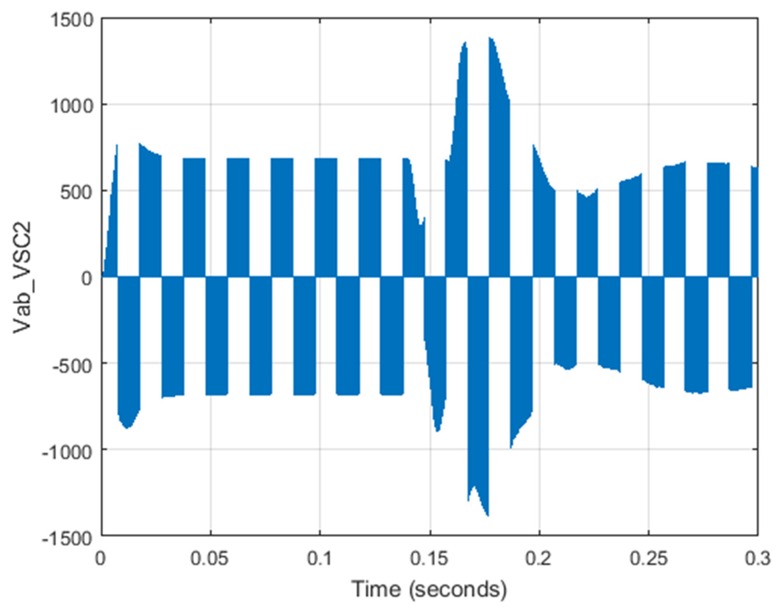
Figure 11.
Two-phase voltage ab for VSC-2.
3.2. Scenario 2: AC Grid Error and Checking Microgrid Becoming Insular
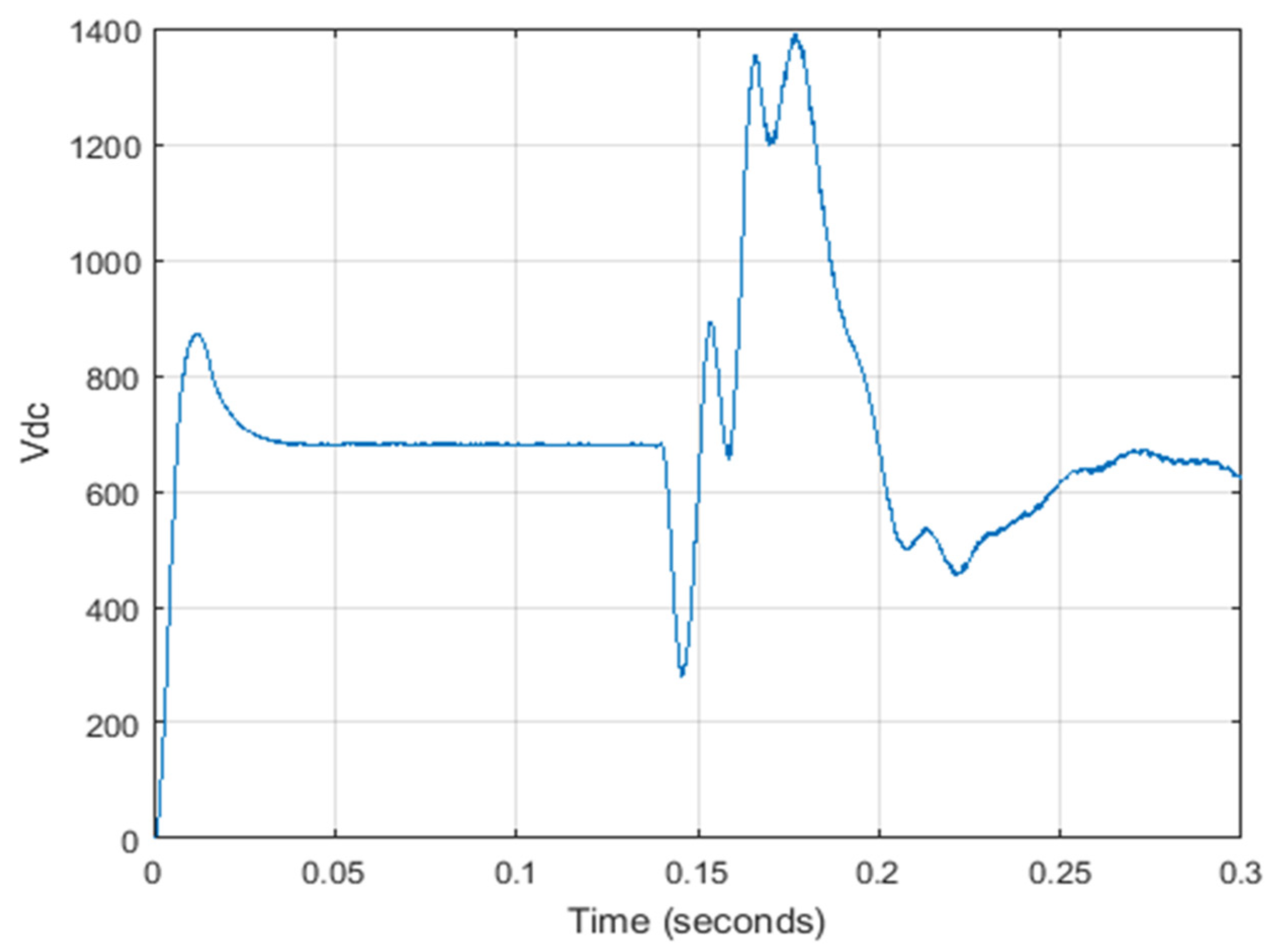
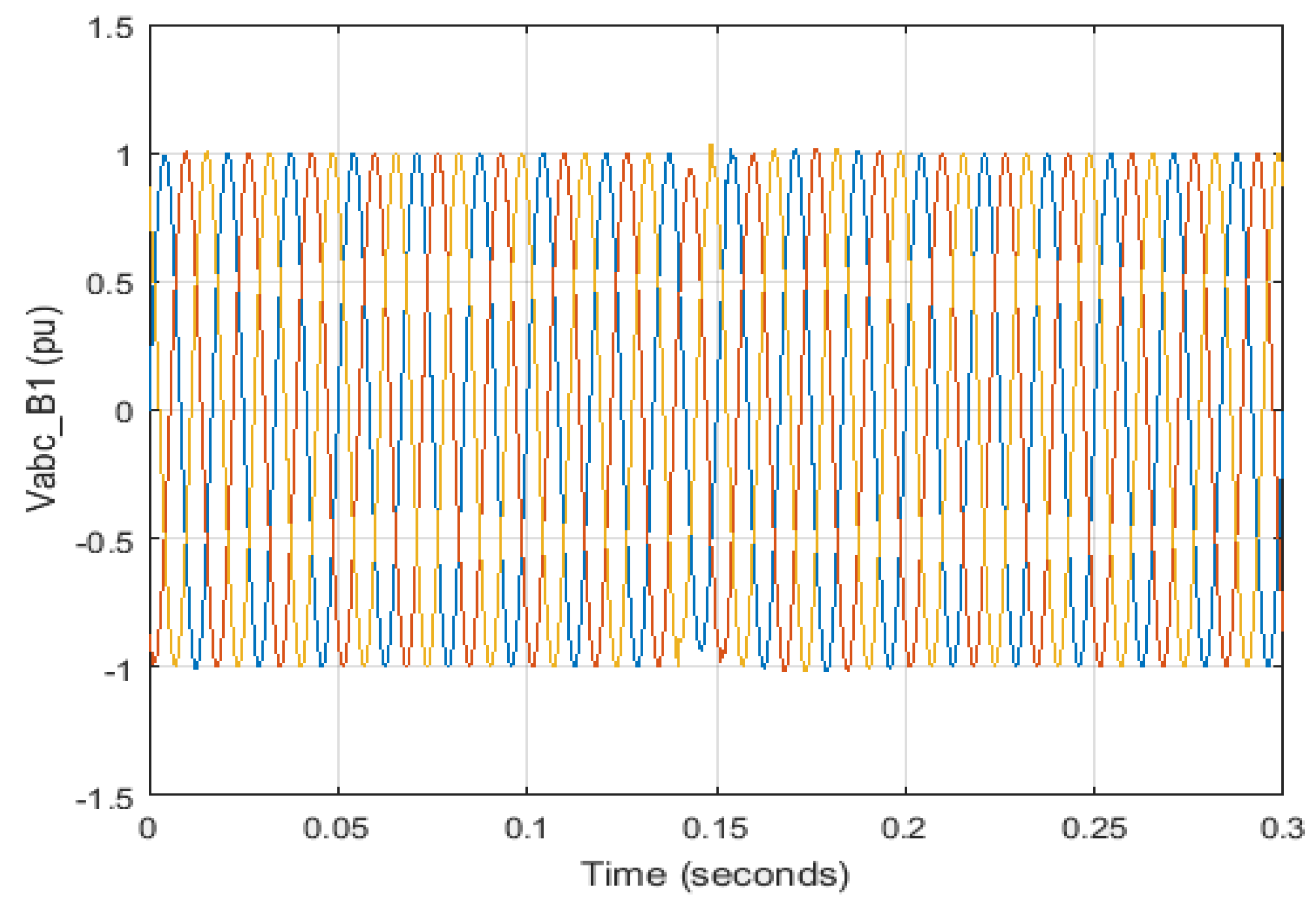
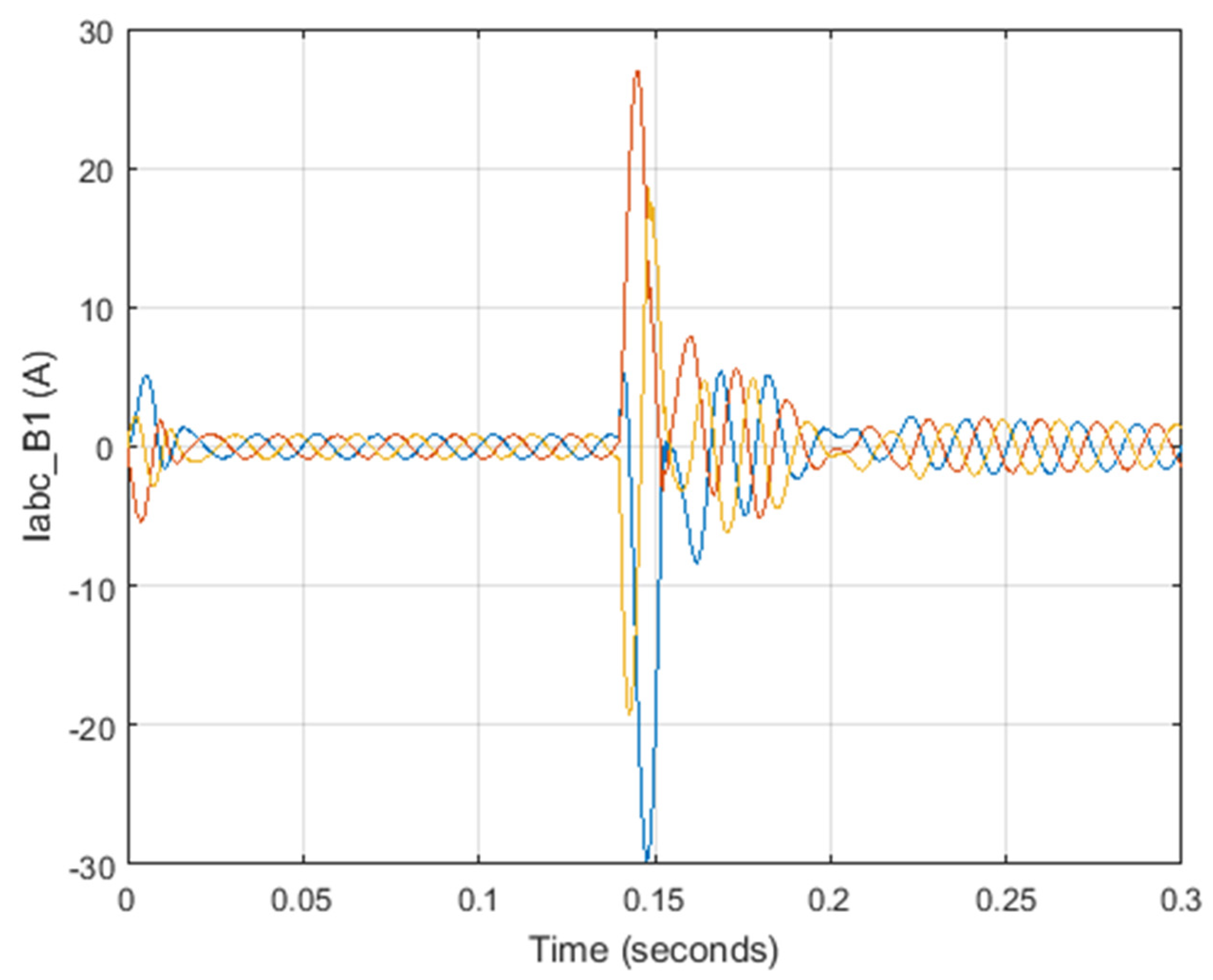
Grid Side Error starts with the error at separators side and blocks VSC-1. Power exchange between microgrids is still possible despite the VSC-2 by changing the voltage control. In this case, a 3-phase connection to the ground on the grid side occurs in second 0.14 for 50 milliseconds and is fixed. Figure 12 shows the DC voltage in scenario 2 when AC grid error occurred. Figure 13 shows the common point voltage between the grid and the microgrid, and Figure 14 shows the current resulting from this.
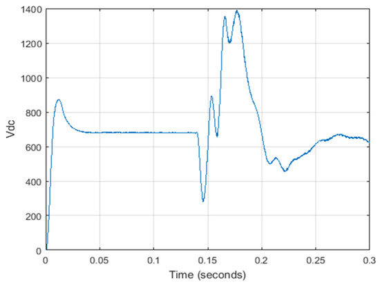
Figure 12.
DC voltage in scenario 2.

Figure 13.
Grid and microgrid voltage common point.
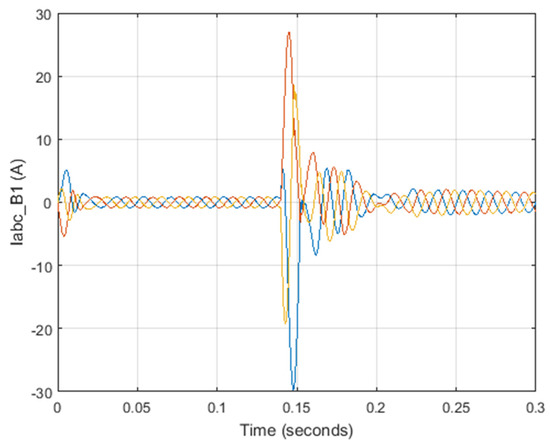
Figure 14.
Common point (common base) grid and microgrid current.
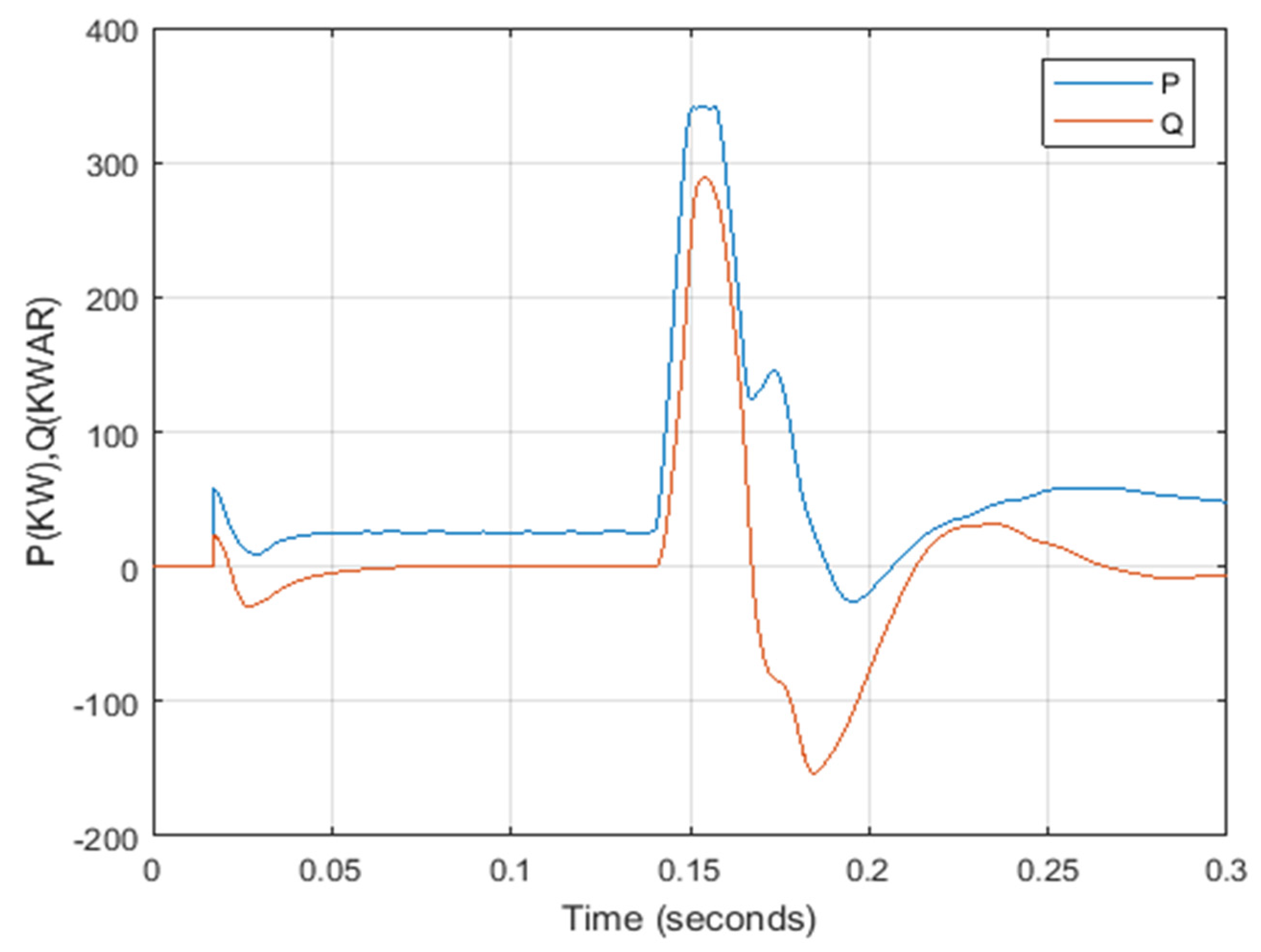
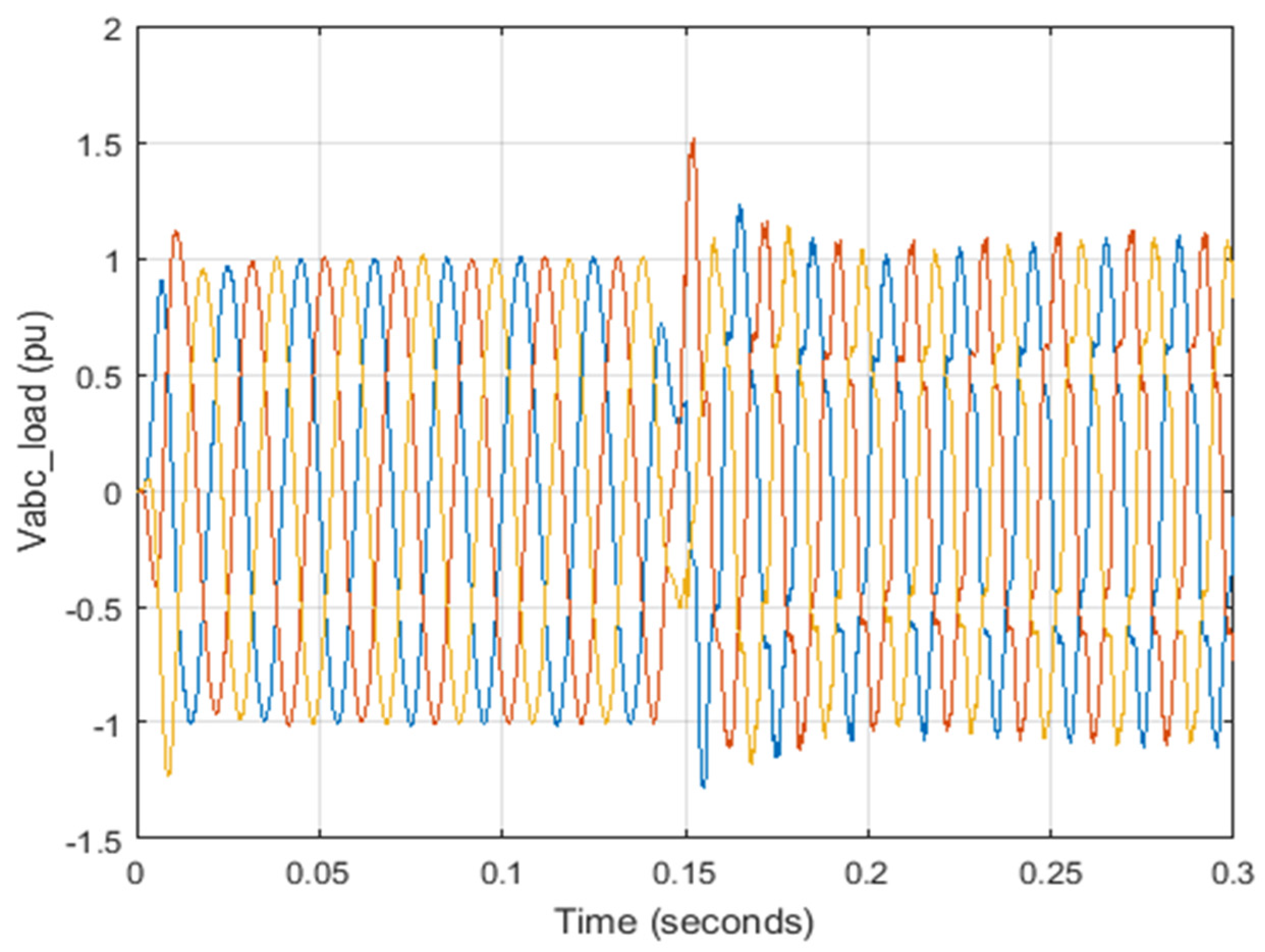
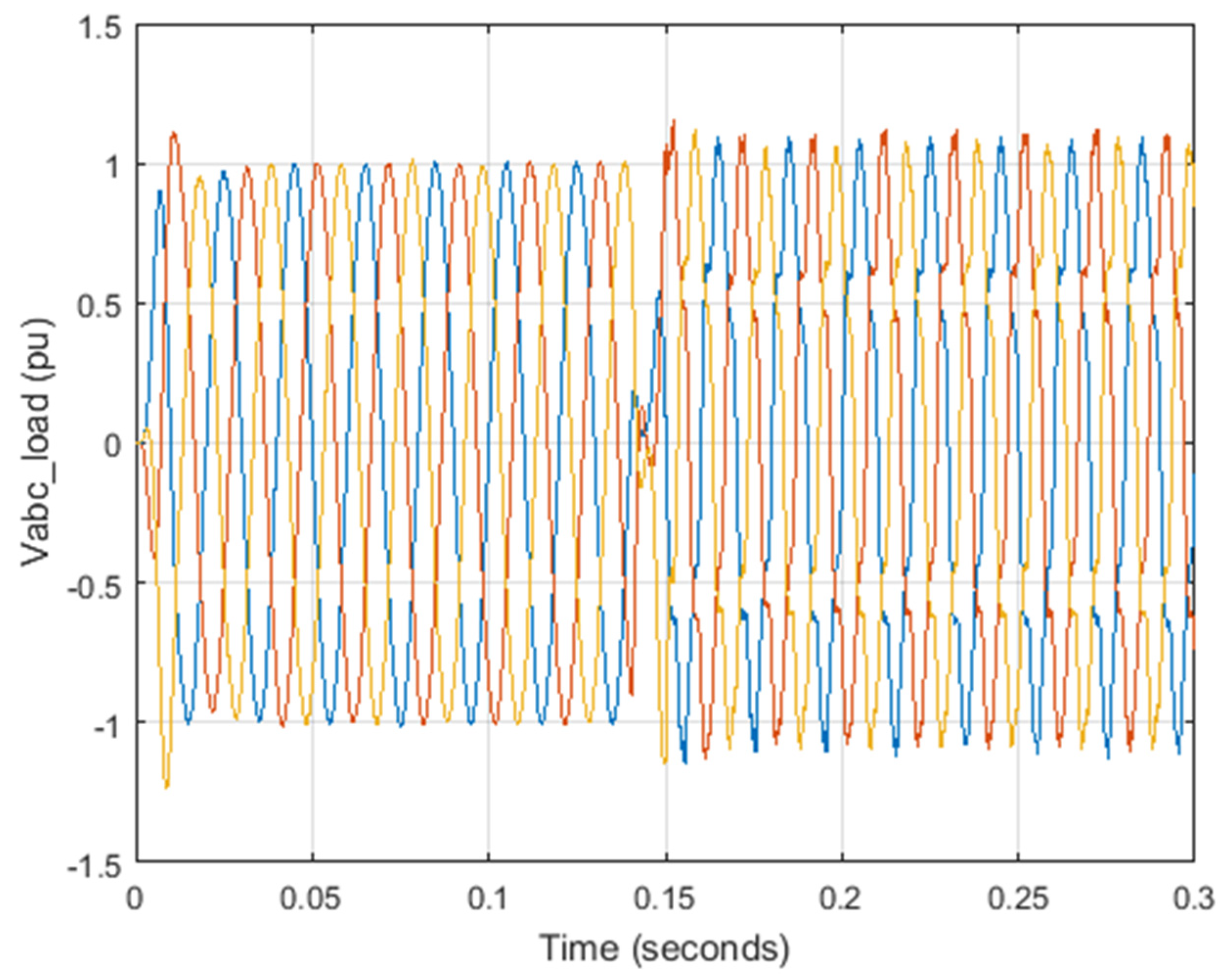
The system operates in two different modes depending on the power requested in the microgrid. In the first case, a certain amount of active and reactive power is provided by the grid to the microgrid through a back-to-back converter, and the remaining requested power is divided proportionally among the DGs according to their output power. When the total power generated by the DGs exceeds the load, the excess power is returned to the grid. This mode results in highly reliable performance. So, the amount of electricity consumed or delivered to the grid is predetermined. Figure 15 shows the power distribution. Figure 16 and Figure 17 show the two-phase voltage of the converters. The voltage of the load is also shown in Figure 18.
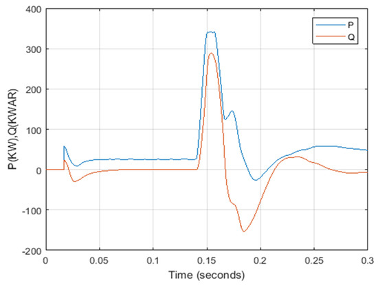
Figure 15.
Active and reactive power distribution.
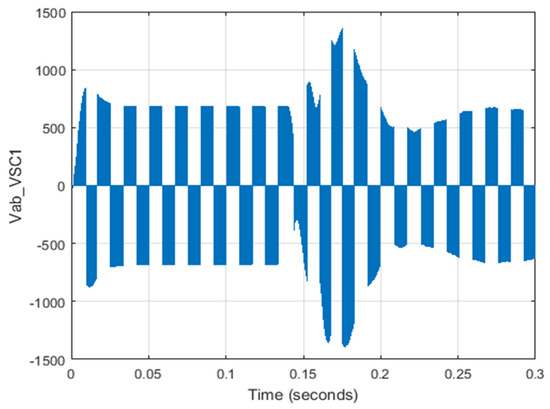
Figure 16.
Two-phase voltage ab for VSC-1.

Figure 17.
Two-phase voltage ab for VSC-2.
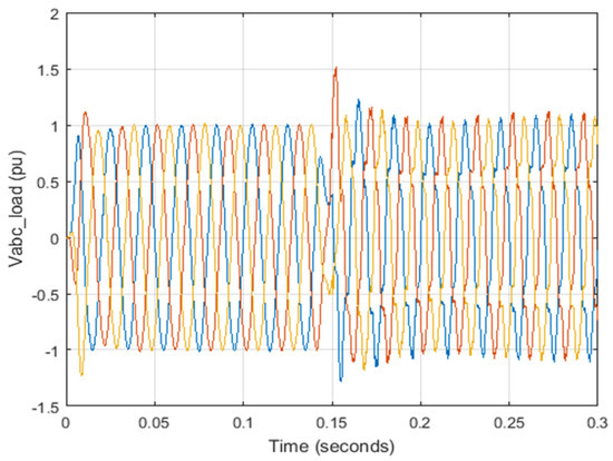
Figure 18.
Load voltage.
3.3. Scenario 3: Error on the Microgrid Side and Checking Becoming Insular
Back-to-back converter base microgrid error: when DC errors occur, the back-to-back converters are blocked, and separators isolate the system. With the loss of grid connection, it may be necessary to change the control mode and reduce the load on the microgrids. It is observed that the DC base voltage is recovered in the period after the error is fixed and the DGs in the DC microgrid provide the additional power required after becoming insular and no disturbance occurs in the flow of the microgrid power. Figure 19 shows the DC voltage values and Figure 20 and Figure 21 show the voltage and current values.
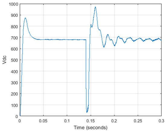
Figure 19.
DC voltage in scenario 3.
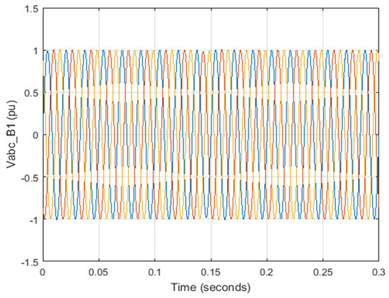
Figure 20.
Grid and microgrid voltage common point.
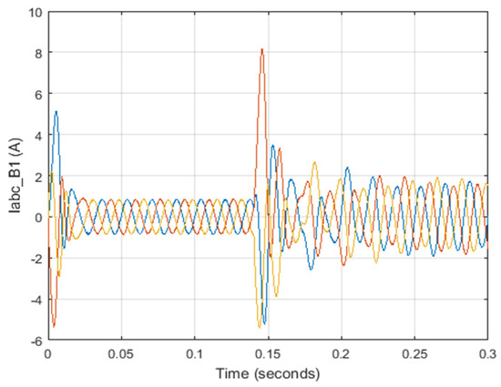
Figure 21.
Common point (common base) grid and microgrid current.
When the power consumption in the microgrid is greater than the total maximum production capacity of the DGs, the power predetermined by the grid is supplied to the microgrid. When the DGs are operating at their maximum power, the grid provides the remaining power consumption in the microgrid under the conditions of the second mode control. When all DGs reach their maximum output range, the microgrid performance changes from mode 1 to mode 2. While mode 1 provides a seamless connection to the grid, mode 2 provides more reliable power and can handle large loads and unstable outputs. Figure 22 shows the power distribution diagram and Figure 23, Figure 24 and Figure 25 show the converter voltage and load diagrams.
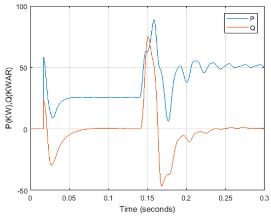
Figure 22.
Active and reactive power distribution.
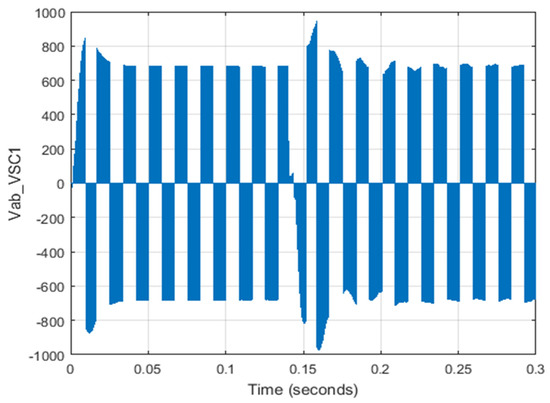
Figure 23.
Two-phase voltage ab for VSC-1.

Figure 24.
Two-phase voltage ab for VSC-2.
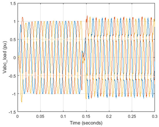
Figure 25.
Load voltage.
4. Conclusions
In this study, a sustainable energy distribution configuration for microgrids integrated to the national grid using back-to-back converters in a renewable power system is investigated. Distributed generators need to use power electronic devices to convert the output to the desirable output. These electronic devices include electronic power converters that can cause harmonic distortion losses to the voltage supply that eventually fluctuate the output voltage. In this paper, the structure of a combined microgrid that is connected to the grid through back-to-back converters is presented. The results implicate that the proposed control configuration provides space for construction and stability of the power system with sustainability of the power management. In addition, according to the various control modes available, the results implicate that the proposed method works properly and stabilizes the network in the shortest possible time. The DC link voltage—despite the decrease in slope controllers, DC power and voltage, as well as power electronic back-to-back converters—is well controlled and ensures stable system performance. Overall, the simulation results show that the proposed system shows acceptable performance under different scenarios. This paper shows that this configuration can be used in remote areas without a power grid or even in areas that, despite the presence of a power grid, tend to use renewable energies, and to supply the output load most of the hours of the day and night.
Author Contributions
Conceptualization, R.A., M.M., S.H., S.M. and D.A.G.; Data Curation, R.A. and F.Z.; Formal Analysis, R.A., F.Z. and M.M.; Funding Acquisition, S.M.; Investigation, R.A. and F.Z.; Methodology, R.A., F.Z., M.M. and S.H.; Project Administration, S.H., S.M. and D.A.G.; Software, R.A., F.Z. and M.M.; Supervision, S.H., S.M. and D.A.G.; Validation, S.M.; Visualization, M.M. and S.H.; Writing—Original Draft, F.Z., M.M., S.H. and S.M.; Writing—Review and Editing, S.H., S.M. and D.A.G. All authors have read and agreed to the published version of the manuscript.
Funding
This research received no external funding.
Acknowledgments
The authors would like to express their appreciation for the international research collaboration between the UK, Italy, and Iran in Renewable Energy.
Conflicts of Interest
The authors declare no conflict of interest.
References
- Khan, A.; Memon, S.; Sattar, T.P. Analyzing integrated renewable energy and smart-grid systems to improve voltage quality and harmonic distortion losses at electric-vehicle charging stations. IEEE Access 2018, 6, 26404–26415. [Google Scholar] [CrossRef]
- Makeen, P.; Ghali, H.A.; Memon, S. Experimental and theoretical analysis of the fast charging polymer lithium-ion battery based on Cuckoo Optimization Algorithm (COA). IEEE Access 2020, 8, 140486–140496. [Google Scholar] [CrossRef]
- Alayi, R.; Jahangeri, M.; Monfared, H. Optimal location of electrical generation from urban solid waste for biomass power plants. Anthropog. Pollut. J. 2020, 4, 44–51. [Google Scholar]
- Yang, L.; Yang, J. A robust dual-loop current control method with a delay-compensation control link for LCL-type shunt active power filters. IEEE Trans. Power Electron. 2018, 34, 6183–6199. [Google Scholar] [CrossRef]
- Alayi, R.; Sobhani, E.; Najafi, A. Analysis of Environmental Impacts on the Characteristics of Gas Released from Biomass. Anthropog. Pollut. J. 2020, 4, 1–14. [Google Scholar]
- He, J.; Li, Y.; Liang, B.; Wang, C. Inverse power factor droop control for decentralized power sharing in series-connected-microconverters-based islanding microgrids. IEEE Trans. Ind. Electron. 2017, 64, 7444–7454. [Google Scholar] [CrossRef]
- Alayi, R.; Rouhi, H. Techno-Economic Analysis of Electrical Energy Generation from Urban Waste in Hamadan, Iran. Int. J. Des. Nat. Ecodynamics 2020, 15, 337–341. [Google Scholar] [CrossRef]
- Alayi, R.; Jahanbin, F. Generation Management Analysis of a Stand-alone Photovoltaic System with Battery. Renew. Energy Res. Appl. 2020, 1, 205–209. [Google Scholar]
- Giraud, F.; Salameh, Z.M. Steady-state performance of a grid-connected rooftop hybrid wind-photovoltaic power system with battery storage. IEEE Trans. Energy Convers. 2001, 16, 1–7. [Google Scholar] [CrossRef]
- Shamel, A.; Marefati, M.; Alayi, R.; Gholaminia, B.; Rohl, H. Designing a PID controller to control a fuel cell voltage using the imperialist competitive algorithm. Adv. Sci. Technol. Res. J. 2016, 10, 176–181. [Google Scholar] [CrossRef] [Green Version]
- Ribeiro, P.F.; Johnson, B.K.; Crow, M.L.; Arsoy, A.; Liu, Y. Energy storage systems for advanced power applications. Proc. IEEE 2001, 89, 1744–1756. [Google Scholar] [CrossRef]
- Gurkaynak, Y.; Khaligh, A. Control and power management of a grid connected residential photovoltaic system with plug-in hybrid electric vehicle (PHEV) load. In Proceedings of the 2009 Twenty-Fourth Annual IEEE Applied Power Electronics Conference and Exposition, Washington, DC, USA, 15–19 February 2009; pp. 2086–2091. [Google Scholar]
- Alayi, R.; Kasaeian, A.; Najafi, A.; Jamali, E. Optimization and evaluation of a wind, solar and fuel cell hybrid system in supplying electricity to a remote district in national grid. Int. J. Energy Sect. Manag. 2020, 14, 408–418. [Google Scholar] [CrossRef]
- Alayi, R.; Harasii, H.; Pourderogar, H. Modeling and optimization of photovoltaic cells with GA algorithm. J. Robot. Control (JRC) 2021, 2, 35–41. [Google Scholar]
- Tan, K.T.; So, P.L.; Chu, Y.C.; Chen, M.Z.Q. Coordinated control and energy management of distributed generation inverters in a microgrid. IEEE Trans. Power Deliv. 2013, 28, 704–713. [Google Scholar] [CrossRef] [Green Version]
- Shahparasti, M.; Savaghebi, M.; Hosseinpour, M.; Rasekh, N. Enhanced circular chain control for parallel operation of inverters in ups systems. Sustainability 2020, 12, 8062. [Google Scholar] [CrossRef]
- Hoke, A.F.; Nelson, A.; Chakraborty, S.; Bell, F.; McCarty, M. An islanding detection test platform for multi-inverter islands using power HIL. IEEE Trans. Ind. Electron. 2018, 65, 7944–7953. [Google Scholar] [CrossRef]
- Haider, S.; Li, G.; Wang, K. A dual control strategy for power sharing improvement in islanded mode of AC microgrid. Prot. Control Mod. Power Syst. 2018, 3, 10. [Google Scholar] [CrossRef]
- Castilla, M.; de Vicuña, L.G.; Miret, J. Control of power converters in AC microgrids. In Microgrids Design and Implementation; Springer: Cham, Switzerland, 2019; pp. 139–170. [Google Scholar]
- Yue, Y.; Chen, Y.; Luo, A.; Ma, F.; Xu, Q.; He, Z. Robust predictive dual-loop control method based on Lyapunov function stability and energy equilibrium though double-core processors for active power filter. Int. J. Electr. Power Energy Syst. 2017, 89, 69–81. [Google Scholar] [CrossRef]
- Çelik, D.; Meral, M.E. Current control based power management strategy for distributed power generation system. Control Eng. Pract. 2019, 82, 72–85. [Google Scholar] [CrossRef]
- Li, L.; Sun, Y.; Liu, Y.; Han, H.; Ye, H.; Su, M.; Shi, G. Power factor consistency control for decentralized power sharing in islanded AC microgrids with cascaded inverters. In Proceedings of the IECON 2017-43rd Annual Conference of the IEEE Industrial Electronics Society, Beijing, China, 29 October–1 November 2017; pp. 1435–1440. [Google Scholar] [CrossRef]
- Das, P.P.; Chattopadhayay, S.; Palmal, M. A d–q voltage droop control method with dynamically phase-shifted phase-locked loop for inverter paralleling without any communication between individual inverters. IEEE Trans. Ind. Electron. 2017, 64, 4591–4600. [Google Scholar] [CrossRef]
- Kasaeian, A.; Shamel, A.; Alayi, R. Simulation and economic optimization of wind turbines and photovoltaic hybrid system with storage battery and hydrogen tank (case study the city of Yazd). J. Curr. Res. Sci. 2015, 3, 105. [Google Scholar]
- Alayi, R.; Ahmadi Kamarposhti, M.; Gharibi, M.; Abbasi zanghaneh, S.; Jahangiri, M. Design and simulation of a hybrid system based on renewable energy for hydrogen production. J. Power Technol. 2020, 100, 331–340. [Google Scholar]
- Alayi, R.; Khan, M.R.B.; Mohmammadi, M.S.G. Feasibility study of grid-connected PV system for peak demand reduction of a residential building in Tehran, Iran. Math. Model. Eng. Probl. 2020, 7, 563–567. [Google Scholar] [CrossRef]
- Ghosh, A.; Joshi, A. A new approach to load balancing and power factor correction in power distribution system. IEEE Trans. Power Deliv. 2000, 15, 417–422. [Google Scholar] [CrossRef]
- Majumder, R.; Ghosh, A.; Ledwich, G.; Zare, F. Power management and power flow control with back-to-back converters in a utility connected microgrid. IEEE Trans. Power Syst. 2009, 25, 821–834. [Google Scholar] [CrossRef] [Green Version]
- Liu, X.; Wang, P.; Loh, P.C. A hybrid AC/DC microgrid and its coordination control. IEEE Trans. Smart Grid 2011, 2, 278–286. [Google Scholar]


Publisher’s Note: MDPI stays neutral with regard to jurisdictional claims in published maps and institutional affiliations. |
© 2021 by the authors. Licensee MDPI, Basel, Switzerland. This article is an open access article distributed under the terms and conditions of the Creative Commons Attribution (CC BY) license (https://creativecommons.org/licenses/by/4.0/).