Article

A Tilt Visible Light Positioning System Based on Double LEDs and Angle Sensors

1
School of Materials Science and Engineering, South China University of Technology, Guangzhou 510640, China
2
School of Electronic and Information Engineering, South China University of Technology, Guangzhou 510640, China
3
School of Automation Science and Engineering, South China University of Technology, Guangzhou 510640, China
4
School of Microelectronics, South China University of Technology, Guangzhou 510655, China
*
Author to whom correspondence should be addressed.
Futong An, Haixin Xu are co-first authors of this article.
Electronics 2021, 10(16), 1923; https://doi.org/10.3390/electronics10161923
Submission received: 5 July 2021 / Revised: 1 August 2021 / Accepted: 4 August 2021 / Published: 10 August 2021
(This article belongs to the Section Microwave and Wireless Communications)

Abstract

:
Visible light positioning (VLP) has been studied widely due to its high accuracy and low cost in the field of location-based services (LBS). However, many existing VLP systems have the requirements that the receiver should be placed horizontally and more than three LED lamps should be used, which are difficult to meet in practical scenarios. Therefore, it is necessary to develop a novel VLP algorithm for tilted conditions. An effective and simple VLP system while the receiver is tilted based on double-LED lamps is proposed in this paper. The vertical position can be determined by combining the information from angle sensors with geometric information. Through analyzing the imaging characteristics of the tilted state, we can utilize the relationship of similarity to calculate the location of the mobile receiver. Experimental results show that the positioning accuracy of our proposed algorithm can reach 5.48 cm.

1. Introduction

With the development of indoor location-based services (LBS), indoor positioning is in urgent need. The widely used Global Positioning System (GPS) cannot be directly applied to an indoor environment because the signal from satellites may be blocked by the wall of buildings [1]. Besides, traditional indoor positioning systems (IPS) such as wireless local area network (WLAN), radio-frequency identification (RFID), Bluetooth and ultra-wideband (UWB) have various limitations in terms of high cost, low accuracy and electromagnetic interference [1]. In contrast, visible light positioning (VLP) based on LED and visible light communication technology is a better choice. Firstly, it does not have the limitations mentioned above. Secondly, energy-efficient LED lamps can be seen everywhere in daily life. Most importantly, the high-frequency flickers are invisible to human eyes, which means that the LED lamps can realize the dual functions of lighting and positioning.
According to the type of receiver, VLP systems can be divided into two categories: image sensor (IS)-based VLP [2,3,4,5] and photodiode (PD)-based VLP [6,7,8,9,10]. For the PD-based VLP, the methods of time of arrival (TOA) [11] and time difference of arrival (TDOA) [12] require high-precision time measurement devices; the received signal strength (RSS) [13] is sensitive to light intensity variation. Angle of arrival (AOA) and RSS have been combined to achieve three-dimensional positioning [14], but the computational complexity and positioning accuracy may not meet our needs. IS-based VLP is more suitable to be applied in indoor environments because it is not sensitive to the diffuse reflection of the light signal and the light intensity variation compared with the PD-based VLP [15,16]. Moreover, smartphones equipped with complementary metal oxide semiconductor (CMOS) image sensors have been widely used, which means that we do not have to pay for the extra receiver.
For IS-based VLP, the LED lamps were treated as point sources without geometric information in the early positioning research. Though centimeter-level accuracy has been achieved in some VLP systems, at least three LEDs should be captured in a picture [17,18]. However, this requirement is difficult to meet in reality, since the camera’s field of view (FOV) is limited, and LED lamps are usually deployed sparsely in a building. Thus, the robustness and flexibility of the VLP system are greatly restricted. In [5,19], angle sensors were employed to “compensate” the receiver’s orientation information in the case of the shortage of LED lamps, and the accuracies of 3.85 and 6.5 cm were achieved. The inaccuracy of azimuthal angle is the main source of the navigation and positioning errors [20,21]. In [22], a positioning accuracy of 17.52 cm was achieved based on a single LED lamp with a marginal point. However, the marked point would be difficult to recognize for the camera as the distance increases. Moreover, most of the algorithms that have been proposed are only applicable when the receiver is in a horizontal state [3,5,23,24,25,26], which restricts the applications of VLP systems.
A tilt positioning system based on double LED and angle sensors is proposed to solve the above problems in this paper. We further explored the geometric features of images and then constructed the equations for the target position. For angle sensors, unlike previous studies such as [23,24,27], only the pitch and roll angles are needed from angle sensors to participate in calculation and selection in our system, which avoids interference from geomagnetism. Generally, VLP is operated in a closed indoor environment, which causes the azimuthal angle measured by the geomagnetic sensor to be affected by walls or other buildings, and azimuthal angle is involved in the calculation in many traditional VLP positioning algorithms. We solved two practical problems to a certain extent: more than three LED lamps are required and algorithms may be invalid when the mobile receiver is tilted. Moreover, the algorithm in this paper is simple to implement and computationally efficient, and it can be practical in subway stations, underground parking lots and so on.

2. Positioning System

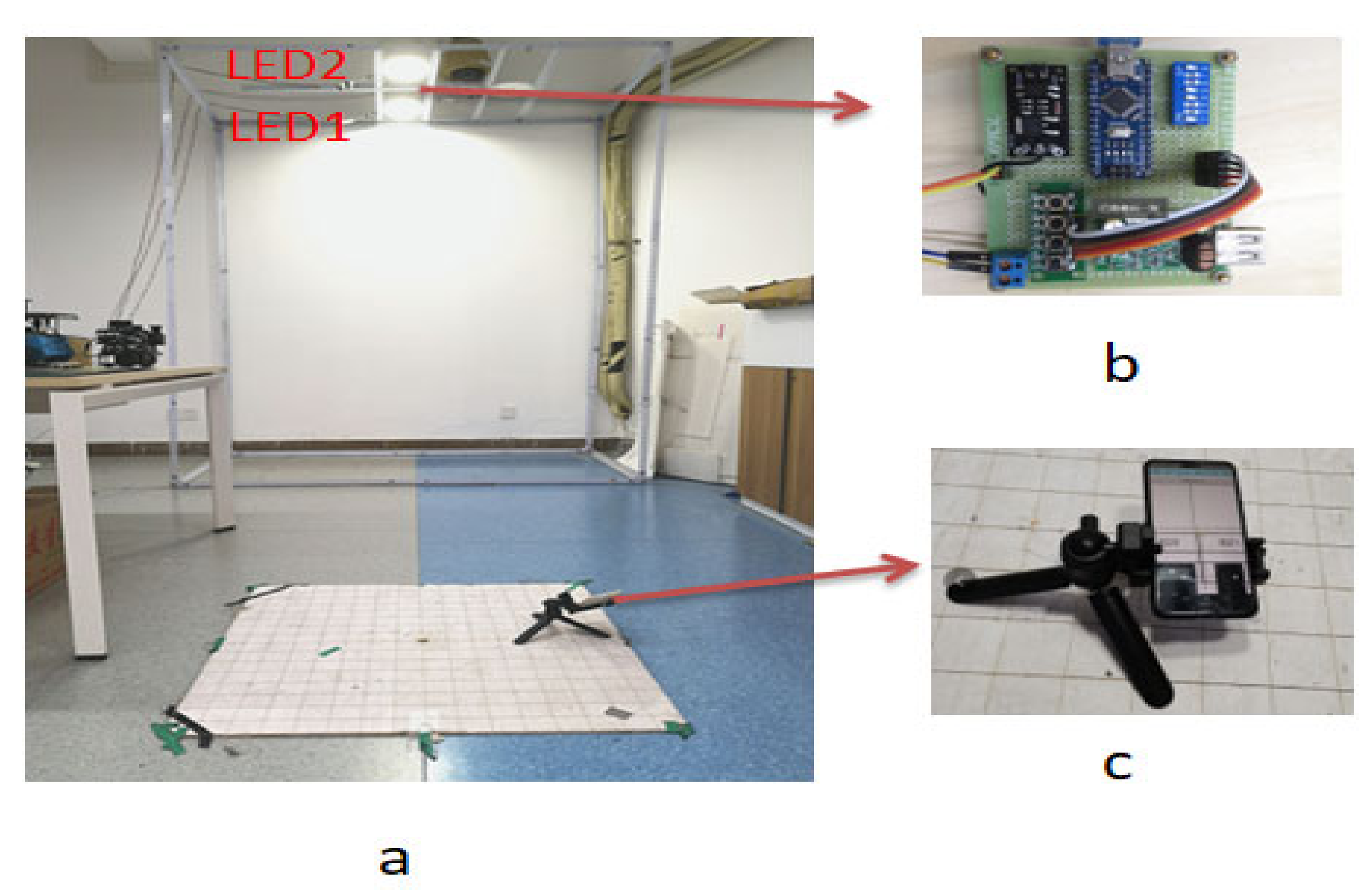
2.1. System Overview

The architecture of our proposed scheme is shown in Figure 1a. LEDs with the radius of R are modulated to broadcast their location signals, and they flash at a frequency that cannot be detected by our eyes. Spatially varying strips can be captured by the camera according to the rolling shutter effect (RSE) [28] as shown in Figure 1b. The mobile receiver can be tilted arbitrarily while capturing, but it should be certain that double-LED lamps are in the FOV of the camera. Then, geometric information and the ID information of LEDs can be obtained through image processing technology. We can obtain the 3D position of the mobile receiver from our proposed algorithm after obtaining the required data.
Figure 2a shows the system model of the proposed algorithm. The centers of LED lamps in a 3D world coordinate system are recorded as X 1 ,   Y 1 ,   Z 1 and X 2 ,   Y 2 ,   Z 2 . Since the lamps are placed at the same height, Z 1 = Z 2 . The midpoint of the lens is estimated to be the terminal position in the 3D coordinate system, which is recorded as point P X , Y , Z . After capturing, the coordinates in the image coordinate system can be calculated as follows:
u = i d i + u 0
v = j d j + v 0
where ( u , v ) is the coordinate in the pixel coordinate system, and u 0 , v 0 is the midpoint.   ( i ,   j ) is the coordinate in the image coordinate system. The unit conversion relationship is 1 pixel = d j mm. The mapped points corresponding to the center of LED1 and LED2 are recorded as i 1 , j 1   and   i 2 , j 2 , and they are both located in the center of the imaging ellipses. The semimajor axes of ellipses are a 1 and a 2 , as shown in Figure 2b. i 0 ,   j 0 is the midpoint of the image coordinate system. f is the parameter of the camera’s focal length. We can read the pitch angle α   along the X-axis and the roll angle β along Y-axis directly through angle sensors. The 3D target location of P is determined by the following description.

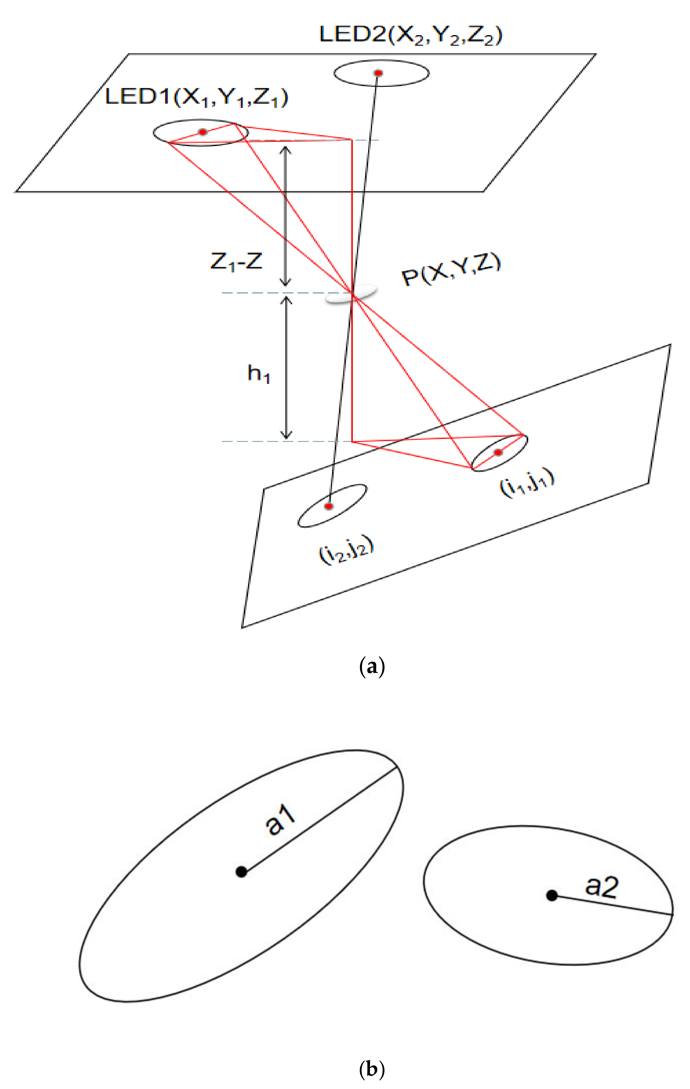
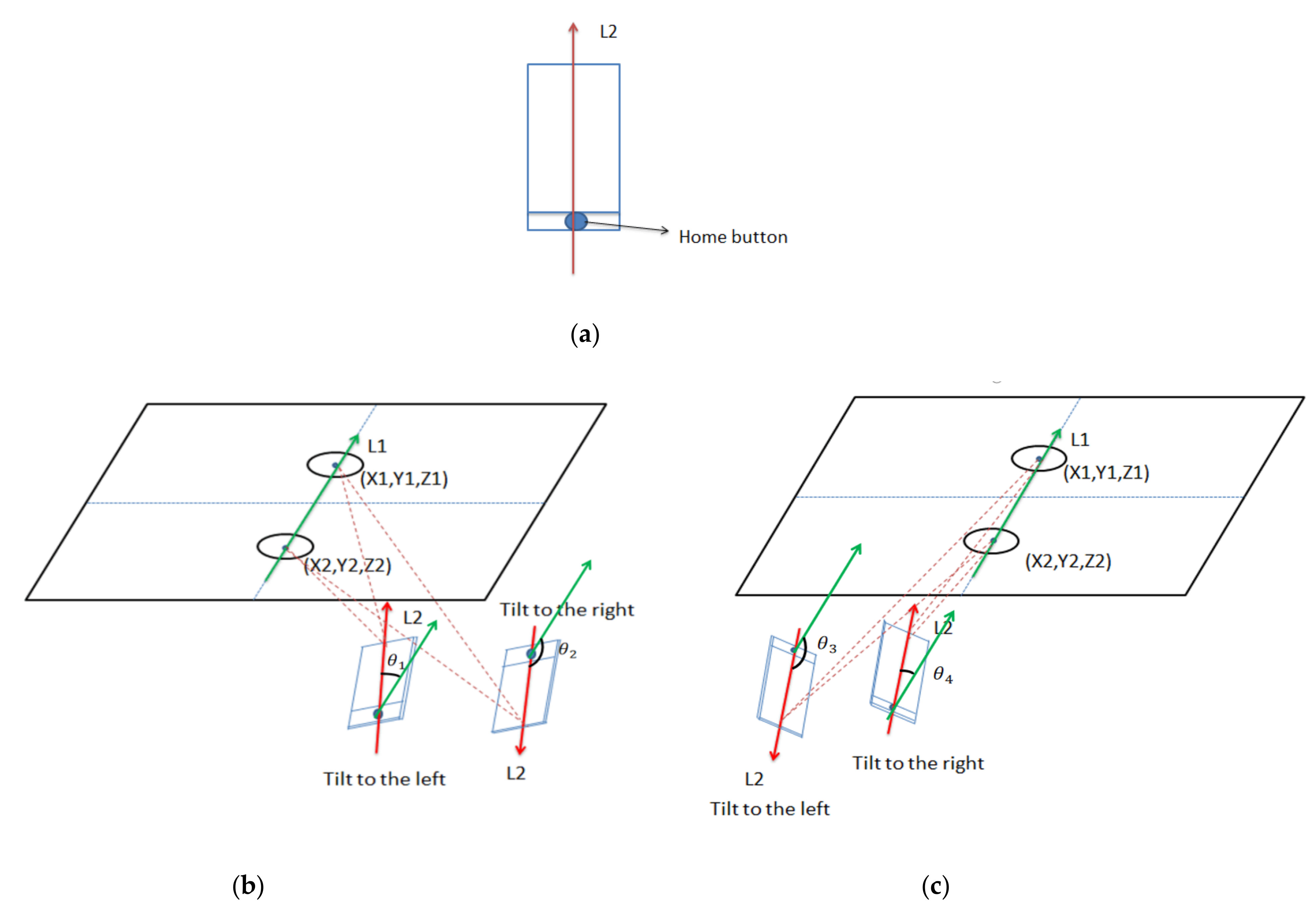
2.2. Principle of Positioning

2.2.1. Calculating Z Coordinate

In the proposed system, an obvious similarity can be found when the receiver is tilted, which refers to that the proportions of the length in a three-sided pyramid is equal to that of another three-sided pyramid. As shown in Figure 2a, the intersection line between the horizontal plane and the imaging plane is exactly parallel to the line where the major axis of the ellipse is located. Thus, the major axis is parallel to a certain radius of the LED lamp, and the two three-sided pyramids in red color in Figure 2a are similar because all corresponding angles between them are the same. Then, we can obtain two equations about Z .
Z 1 Z R   = h 1 a 1
  Z 2 Z R   = h 2 a 2
where h k   k = 1 ,   2 is the vertical distance from the lens to the horizontal plane where the major axis is located.
Figure 3 shows different situations based on the position of the ellipse in the image. Then, we can obtain h k in two cases for each LED.
h 1 h 1 = f d 1 f d 1 cos t tan t cos t
h 2 h 2 = f d 2 f d 2 cos t tan t cos t
where d k = i k i 0 2 + j k j 0 2 (k = 1, 2); t is the angle between the imaging plane and the horizontal plane, which can be calculated through cos t = cos α cos β . h k k = 1 ,   2 and h k k = 1 ,   2 represent the h k when the ellipse is on the upper or lower side of the horizontal line passing through the center. However, only two of h k k = 1 ,   2 and h k k = 1 ,   2 are correct, since the state of each ellipse is fixed in one image.
We do not pick the correct h k k = 1 ,   2 for each ellipse in the next step, but substitute h k and h k into h k (k = 1, 2) in Equations (3) and (4).
Z 11 Z 12 = Z 1 Z 1 R a 1 · h 1 h 1
Z 21 Z 22 = Z 2 Z 2 R a 2 · h 2 h 2
where only two of Z m n   (m = 1, 2; n = 1, 2) are the target values for Z in a picture, and they should be the same in theory. However, the two correct values are different due to the existence of deviations in reality. So, there is a difference between Z 1 p and Z 2 q (p = 1, 2; q = 1, 2), and Z can be calculated by
Z = Z 1 p + Z 2 q 2
where Z 1 p   and   Z 2 q   are the Z 1 p and Z 2 q (p = 1, 2; q = 1, 2) with the smallest difference. Z mn is the Z coordinate value obtained under different assumptions. However, the previous calculation contains right and wrong situations, and the actual situation is only the correct situation. Thus, it is impossible to determine the true value of Z . Z 1 p and Z 2 q are the cases when m = 1 and m = 2 in Z mn . Z 1 p represents the two Z coordinates calculated according to LED1, one of which is correct and the other of which is wrong; Z 2 q represents the two Z coordinates calculated based on LED2, one of which is correct and the other of which is wrong similarly. The two correct results of Z mn should be the same theoretically, but the two correct values will not be completely equal due to the existence of the deviation. Thus, we calculated the average of the two values with the smallest difference as the final Z coordinate, because the theoretical difference between the wrong value and the right value of Z is 2 d 1 sin ( t ) R a 1 or 2 d 2 sin ( t ) R a 2 . The difference varies with the change of t or dk. The four Zmn values will actually be very close when t or dk is small or even equal to 0. Therefore, the average value can also be regarded as the value of Z .

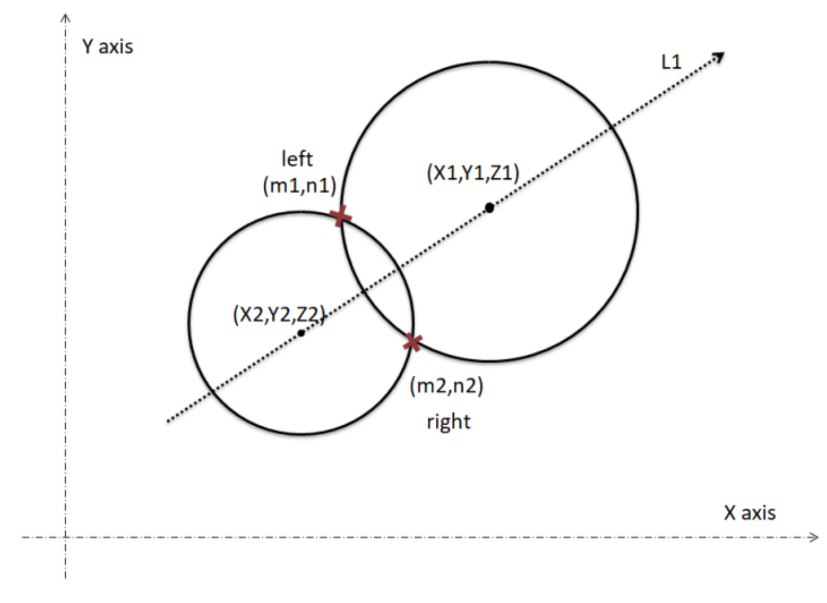
2.2.2. Calculating X and Y Coordinates

The similarity relationship described above can also be expressed by the following equations:
a 1 R   = f 2 + d 1 ^ 2 X X 1 2 + Y Y 1 2 + Z Z 1 ^ 2
a 1 R   = f 2 + d 2 ^ 2 X X 2 2 + Y Y 2 2 + Z Z 2 ^ 2
where only X and Y are unknown. Substituting the Z coordinate obtained into (10) and (11), we can obtain two different solutions for (X, Y), which can be regarded as the intersection points of two circles, as shown in Figure 4. However, only one of the solutions is the real position of the receiver, since the same values of t , d k and a k may be taken in the symmetrical position of the LED lamps.
The following description is the process of selecting the position of the receiver based on the vector and angle information. The double-LED vector L 1 refers to the direction vector from the center of LED2 to the center of LED1 in the world coordinate system; the   vector   of   receiver   L 2   refers to the direction vector from the bottom of the phone to the top in the world coordinate system, as shown in Figure 5. The angle between L1 and L2 is denoted as θ , which can be calculated through a captured image of the LED lightings and can be expressed as (12).
a r c t a n j 2 j 1 i 2 i 1 ;   i 2 i 1 > 0 a r c t a n j 2 j 1 i 2 i 1 + π ;   j 2 j 1 0 , i 2 i 1 < 0 θ = a r c t a n j 2 j 1 i 2 i 1 π ;   j 2 j 1 < 0 ,   i 2 i 1 < 0 + π 2 ;   j 2 j 1 > 0 ,   i 2 i 1 = 0 π 2 ;   j 2 j 1 < 0 ,   i 2 i 1 = 0 u n d e f i n e d ;   j 2 j 1 = 0 , i 2 i 1 = 0
It is required that the receiver is always placed towards the double LED, as shown in Figure 5. When the angle θ is acute and the receiver is tilted to the left, or the angle θ is obtuse and the receiver is tilted to the right, the solution on the right side of L1 should be chosen. Conversely, when the angle θ is acute and the receiver is tilted to the right, or when the angle θ is obtuse and the receiver is tilted to the left, the solution on the left side of L1 should be chosen. The target position can be determined from two solutions according to this method.

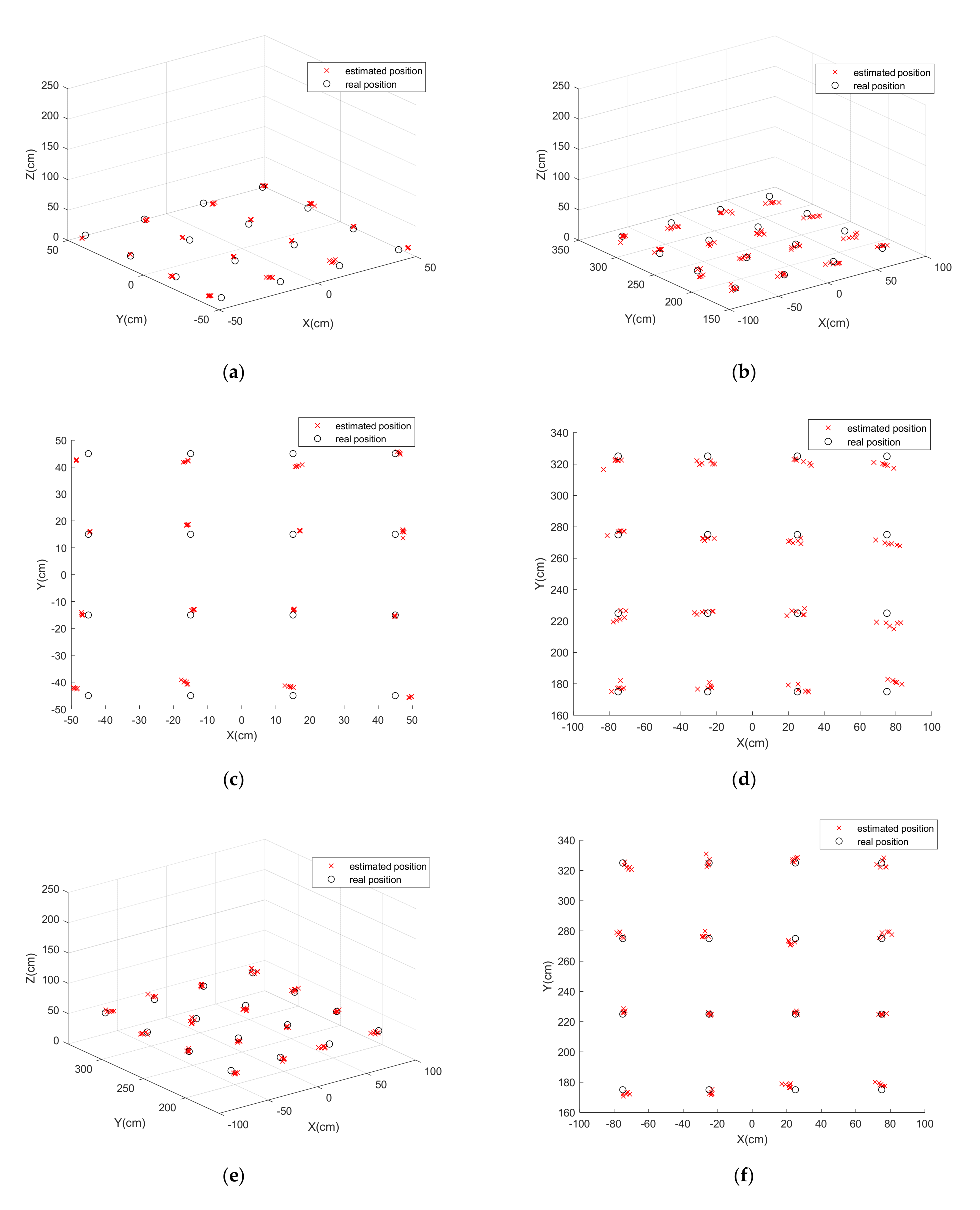
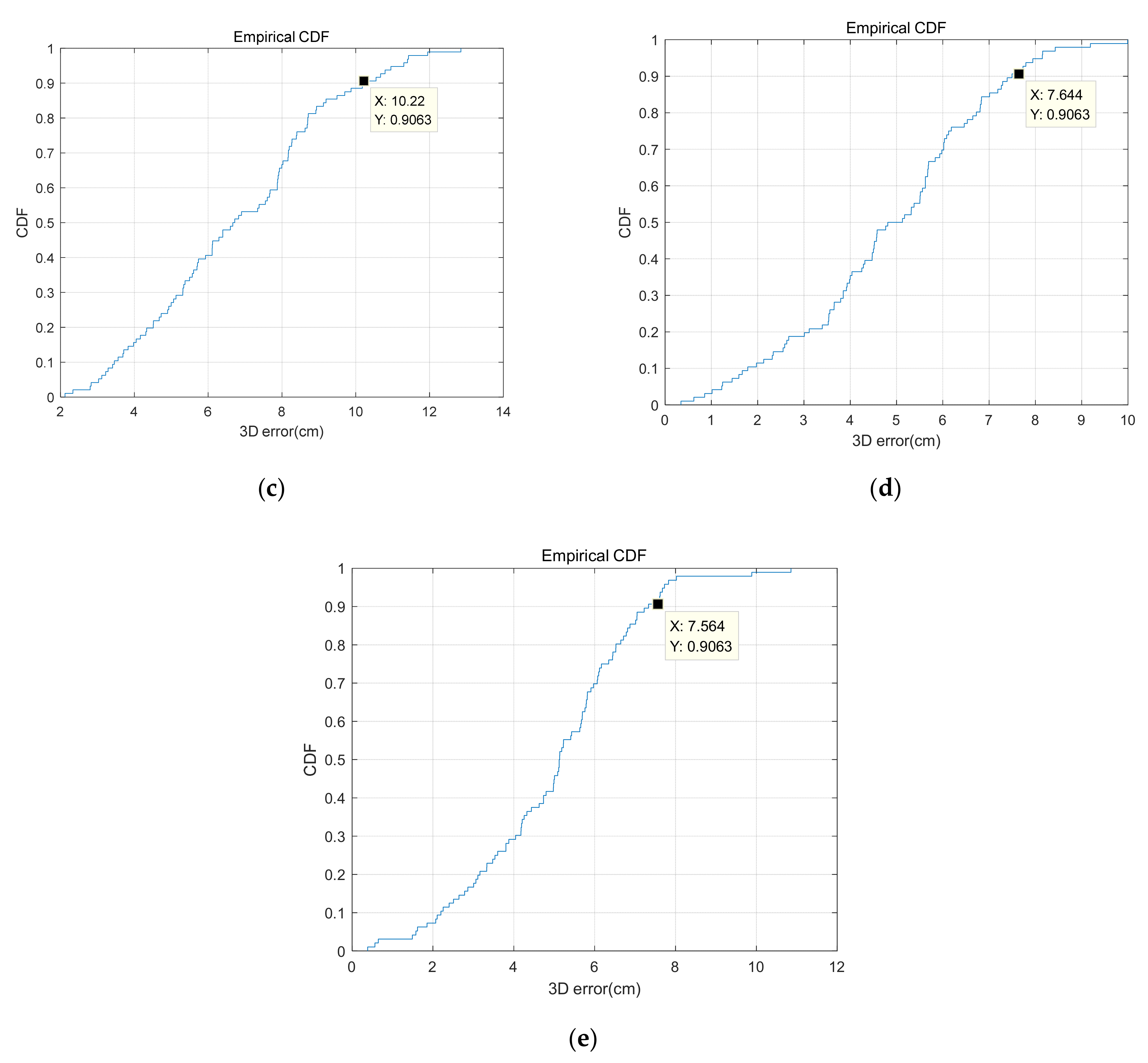
3. Experiment and Analysis

A series of experiments were conducted to test the performance of the proposed system. As shown in Figure 6, we tested the accuracy in an area of 400 cm × 200 cm × 250 cm (L × W × H). The radius of the LED was 8.75 cm. The larger the radius of the LED, the smaller the relative error caused by the blurred boundary. On–off keying intensity modulation (OOK IM) was used while driving the LED lamps. The purpose of modulation is to determine the position of the LEDs in the 3D world coordinate system based on the stripe information. More information about modulation and demodulation can be found in our previous work [29,30]. We connected the 60 V DC power supply to the circuit board so that the DC power with a flashing signal would light up the LEDs. The modulator and the receiver are shown in Figure 6b,c. We used a Huawei P20 phone as the receiver to capture double-LED lamps and then calculate the position. The specific system parameters are shown in Table 1.
In this experiment to test the accuracy, the coordinates of the double LEDs were set to 0 , 30 , 250 and 0 , 30 , 250 ; the unit is cm. We evenly took 16 points to record the times at the height of 0.1 m. In order to reduce accidental errors, we tested six times for every point, keeping the compound angle t constant every time. The 3D positioning results are shown in Figure 7. The average distance from the receiver to the double-LED lamps is recorded as D.
As shown in Figure 7a, an average error of 4.28 cm was achieved when the vertical distance was 240 cm and the tilt angle t was less than 3 ° . To further analyze the performance of our proposed algorithm, the cumulative distribution function (CDF) of estimated errors was generated under different conditions. More than 90 % of the errors are less than 5.908   cm when   t < 3 °   and   D 250   cm , as shown in Figure 8a. Figure 8b shows the results of positioning when t 30 °   and   D 250   cm . The large deviation is mainly caused by the assumption of the weak perspective projection, which means that the object size should be small enough with respect to the distance from the viewer to the object [31]. Thus, we conducted the third experiment under this condition. Figure 7b and Figure 8c show the results when t 30 °   and   D > 300   cm . An average error of 6.8 cm was achieved and over 90 % of positioning error was within 10.22 cm. In addition, we conducted additional tests at different heights to confirm the feasibility of the algorithm. Figure 7e,h and Figure 8d,e show the high accuracy of our algorithm at the heights 0.5 and 1 m.
Two error sources were unavoidable in the process of the experiments. One is that there may be errors in the placement of the camera and the installation of LEDs. The other is that the image becomes blurred gradually as the distance increases. In the case of considering experimental errors, the average error of the algorithm is within 5.48 cm, which indicates that the error of our proposed algorithm is theoretically lower.

4. Conclusions

In this paper, we propose a tilt visible light positioning system based on double LEDs and angle sensors, which explored the vertical distance from the lens to the horizontal plane where the major axis of the ellipse is located. This system solves several problems: the requirement for horizontal placement of the receiver, the dependence on a geomagnetic sensor and the requirement of more than three LEDs in some VLP systems. In the process of experimental verification, our proposed algorithm had an excellent performance, achieving an average 3D positioning error of 5.54 cm in an area of 400 cm × 200 cm × 250 cm. It is possible to capture a clearer image by increasing the pixel size of the receiver and controlling the distance D, which will further improve the positioning accuracy. We also hope that future research will further reduce the dependence on angle sensors.

Author Contributions

Conceptualization, W.G.; methodology, F.A.; software, H.X.; validation, F.A., H.X. and W.G.; formal analysis, Z.C.; investigation, F.A.; resources, S.W.; data curation, F.A. and H.X.; writing—original draft preparation, F.A.; writing—review and editing, F.A. and H.S.; visualization, F.A.; supervision, S.W.; project administration, W.G. and S.W.; funding acquisition, S.W. All authors have read and agreed to the published version of the manuscript.

Funding

This research was funded by the Research and Development Program in Key Areas of Guangdong Province (2019B010116002), the National Undergraduate Innovation and Entrepreneurship Training Program (202010561020) and the Guangdong Science and Technology Project under grant 2017B010114001.

Institutional Review Board Statement

Not applicable.

Informed Consent Statement

Not applicable.

Data Availability Statement

The study did not report any data.

Conflicts of Interest

The authors declare no conflict of interest.

References

  1. Lin, P.; Hu, X.; Ruan, Y.; Li, H.; Fang, J.; Zhong, Y.; Zheng, H.; Fang, J.; Jiang, Z.L.; Chen, Z. Real-time Visible Light Positioning Supporting Fast Moving Speed. Opt. Express 2020, 28, 14503–14510. [Google Scholar] [CrossRef] [PubMed]
  2. Fang, J.; Yang, Z.; Long, S.; Wu, Z.; Zhao, X.; Liang, F.; Jiang, Z.L.; Chen, Z. High-speed indoor navigation system based on visible light and mobile phone. IEEE Photonics J. 2017, 9, 1–11. [Google Scholar] [CrossRef]
  3. Guan, W.; Wen, S.; Liu, L.; Zhang, H. High-precision indoor positioning algorithm based on visible light communication using complementary metal–oxide–semiconductor image sensor. Opt. Eng. 2019, 58, 024101. [Google Scholar] [CrossRef]
  4. Yasir, M.; Ho, S.W.; Vellambi, B. NIndoor Positioning System Using Visible Light and Accelerometer. J. Lightwave Technol. 2014, 32, 3306–3316. [Google Scholar] [CrossRef]
  5. Guan, W.; Wen, S.; Zhang, H.; Liu, L. A Novel Three-dimensional Indoor Localization Algorithm Based on Visual Visible Light Communication Using Single LED. In Proceedings of the 2018 IEEE International Conference on Automation, Electronics and Electrical Engineering (AUTEEE), Shenyang, China, 16–18 November 2018; pp. 202–208. [Google Scholar]
  6. Cai, Y.; Guan, W.; Wu, Y.; Xie, C.; Chen, Y.; Fang, L. Indoor high precision three-dimensional positioning system based on visible light communication using particle swarm optimization. IEEE Photonics J. 2017, 9, 1–20. [Google Scholar] [CrossRef]
  7. Shen, S.; Li, S.; Steendam, H. Simultaneous Position and Orientation Estimation for Visible Light Systems with Multiple LEDs and Multiple PDs. IEEE J. Sel. Areas Commun. 2020, 38, 1866–1879. [Google Scholar] [CrossRef]
  8. Chen, B.; Jiang, J.; Guan, W.; Wen, S.; Li, J.; Chen, Y. Performance comparison and analysis on different optimization models for high-precision three-dimensional visible light positioning. Opt. Eng. 2018, 57, 125101. [Google Scholar] [CrossRef]
  9. Li, Y.; Ghassemlooy, Z.; Tang, X.; Lin, B.; Zhang, Y. A VLC Smartphone Camera Based Indoor Positioning System. IEEE Photonics Technol. Lett. 2018, 30, 1171–1174. [Google Scholar] [CrossRef]
  10. Lin, B.; Ghassemlooy, Z.; Lin, C.; Tang, X.; Li, Y.; Zhang, S. An Indoor Visible Light Positioning System Based on Optical Camera Communications. IEEE Photonics Technol. Lett. 2017, 29, 579–582. [Google Scholar] [CrossRef]
  11. Guvenc, I.; Chong, C.C. A surveyon TOAbased wirelesslocalization and NLOS mitigation techniques. IEEE Commun. Surv. Tutor. 2009, 11, 107–124. [Google Scholar] [CrossRef]
  12. Do, T.H.; Yoo, M. TDOA-based indoor positioning using visible light. Photon. Netw. Commun. 2014, 27, 80–88. [Google Scholar] [CrossRef]
  13. Angjelichinoski, M.; Denkovski, D.; Atanasovski, V.; Gavrilovska, L. Cramér–Rao lower bounds of RSS-based localization with anchor position uncertainty. IEEE Trans. Inf. Theory 2015, 61, 2807–2834. [Google Scholar] [CrossRef]
  14. Komine, T.; Nakagawa, M. Integrated system of white LED visible-light communication and power-line communication. IEEE Trans. Consum. Electron. 2003, 49, 71–79. [Google Scholar] [CrossRef] [Green Version]
  15. Shi, J.; He, J.; Jiang, Z.; Chang, G.K. Modulation Format Shifting Scheme for Optical Camera Communication. IEEE Photonics Technol. Lett. 2020, 32, 1167–1170. [Google Scholar] [CrossRef]
  16. Zhou, Z.; Wen, S.; Guan, W. RSE-based optical camera communication in underwater scenery with bubble degradation. In Proceedings of the 2021 Optical Fiber Communications Conference and Exhibition (OFC), San Francisco, CA, USA, 6–10 June 2021; pp. 1–3. [Google Scholar]
  17. Kuo, Y.S.; Pannuto, P.; Hsiao, K.J.; Dutta, P. Luxapose: Indoor Positioning with Mobile Phones and Visible Light. In Proceedings of the 20th Annual International Conference on Mobile Computing and Networking, Maui, HI, USA, 7–11 September 2014; pp. 447–458. [Google Scholar]
  18. Nakazawa, Y.; Makino, H.; Nishimori, K.; Wakatsuki, D.; Komagata, H. Indoor positioning using a high-speed, fish-eye lens-equipped camera in visible light communication. In Proceedings of the 2013 International Conference on Indoor Positioning and Indoor Navigation, Montbeliard, France, 28–31 October 2013; pp. 1–8. [Google Scholar]
  19. Kim, J.-Y.; Yang, S.-H.; Son, Y.-H.; Han, S.-K. High-resolution indoor positioning using light emitting diode visible light and camera image sensor. IET Optoelectron. 2016, 10, 184–192. [Google Scholar] [CrossRef]
  20. Shala, U.; Rodriguez, A. Indoor Positioning Using Sensor-Fusion in Android Devices. Master’s Thesis, Kristianstad University, Kristianstad, Sweden, 2011. [Google Scholar]
  21. Li, F.; Zhao, C.; Ding, G.; Gong, J.; Liu, C.; Zhao, F. A reliable and accurate indoor localization method using phone inertial sensors. In Proceedings of the 2012 ACM Conference on Ubiquitous Computing, Pittsburgh, PA, USA, 5–8 September 2012; pp. 421–430. [Google Scholar]
  22. Zhang, R.; Zhong, W.D.; Kemao, Q.; Zhang, S. A Single LED Positioning System Based on Circle Projection. IEEE Photonics J. 2017, 9, 1–9. [Google Scholar] [CrossRef]
  23. Chen, S.; Guan, W. High Accuracy VLP based on Image Sensor using Error Calibration Method. arXiv 2020, arXiv:2010.00529. [Google Scholar]
  24. Guan, W.; Huang, L.; Hussain, B.; Yue, C.P. Robust Robotic Localization using Visible Light Positioning and Inertial Fusion. IEEE Sens. J. 2021. [Google Scholar] [CrossRef]
  25. Amsters, R.; Holm, D.; Joly, J.; Demeester, E.; Stevens, N.; Slaets, P. Visible Light Positioning Using Bayesian Filters. J. Lightwave Technol. 2020, 38, 5925–5936. [Google Scholar] [CrossRef]
  26. Liang, Q.; Lin, J.; Liu, M. Towards Robust Visible Light Positioning Under LED Shortage by Visual-inertial Fusion. In Proceedings of theThe International Conference on Indoor Positioning and Indoor Navigation (IPIN 2019), Pisa, Italy, 28 November 2019. [Google Scholar]
  27. Cheng, H.; Xiao, C.; Ji, Y.; Ni, J.; Wang, T. A Single LED Visible Light Positioning System Based on Geometric Features and CMOS Camera. IEEE Photonics Technol. Lett. 2020, 32, 1097–1100. [Google Scholar] [CrossRef]
  28. Danakis, C.; Afgani, M.; Povey, G.; Underwood, I.; Haas, H. Using a CMOS camera sensor for visible lightcommunication. In Proceedings of the IEEE Global Telecommun Conference Workshops, Anaheim, CA, USA, 3–7 December 2012; pp. 1244–1248. [Google Scholar]
  29. Song, H.; Wen, S.; Yuan, D.; Huang, L.; Yan, Z.; Guan, W. Robust LED region-of-interest tracking for visible light positioning with low complexity. Opt. Eng. 2021, 60, 053102. [Google Scholar] [CrossRef]
  30. Zhou, Z.; Wen, S.; Li, Y.; Xu, W.; Chen, Z.; Guan, W. Performance Enhancement Scheme for RSE-Based Underwater Optical Camera Communication Using De-Bubble Algorithm and Binary Fringe Correction. Electronics 2021, 10, 950. [Google Scholar] [CrossRef]
  31. Safaee-Rad, R.; Tchoukanov, I.; Smith, K.C.; Benhabib, B. Three-dimensional location estimation of circular features for machine vision. IEEE Trans. Robot. Autom. 1992, 8, 624–640. [Google Scholar] [CrossRef] [Green Version]
Figure 1. (a) Architecture of indoor positioning technology using double LEDs; (b) LED lamps with high-frequency flicker.
Electronics 10 01923 g001
Figure 2. (a) Double-LED positioning system model; (b) an example of semimajor axes a1 and a2.
Electronics 10 01923 g002
Figure 3. Different situations while imaging: (a) on the upper side; (b) on the lower side.
Electronics 10 01923 g003
Figure 4. m 1 ,   n 1   and   m 2 ,   n 2 are the solutions of the equations for (X, Y).
Electronics 10 01923 g004
Figure 5. The receiver in different states: (a) model of the receiver; (b) selecting the right solution; (c) selecting the left solution.
Electronics 10 01923 g005
Figure 6. Experimental setup for evaluating the proposed algorithm: (a) experimental platform; (b) the modulator; (c) the receiver.
Electronics 10 01923 g006
Figure 7. Positioning results with different heights or horizontal distances: (a,b) the 3D positioning results at the height of 10 cm; (c,d) the horizontal view of the 3D positioning results at the height of 10 cm; (e,f) positioning results at the height of 50 cm; (g,h) positioning results at the height of 100 cm.
Electronics 10 01923 g007aElectronics 10 01923 g007b
Figure 8. The CDF plot of the 3D positioning error under different conditions: (a)   t < 3 ° ,   D 250   cm ; (b) t 30 ° ,   D 250   cm ; (c)   t 30 ° ,   D > 300   cm ; (d) t 30 ° , at the height of 50 cm; (e) t < 3 ° , at the height of 100 cm (angle t is shown in Figure 3).
Electronics 10 01923 g008aElectronics 10 01923 g008b
Table 1. Parameters in this study.
ParameterValue
Resolution1920 × 1080
The focal length18 mm
FOV of cameraϕ ≈ 50.4 °
Power of each LED18 W
Camera exposure time0.05 ms
Publisher’s Note: MDPI stays neutral with regard to jurisdictional claims in published maps and institutional affiliations.

