Article

Design of Dual Ultra–Wideband Band–Pass Filter Using Stepped Impedance Resonator λg/4 Short Stubs and T–Shaped Band-Stop Filter

1
Department of Biomedical Engineering, College of Medicine, Gachon University, 38-13, Dokjom-ro 3, Namdong-gu, Incheon 21565, Korea
2
Medical Devices R&D Center, Gachon University Gil Hospital, 21, 774 beon-gil, Namdong-daero Namdong-gu, Incheon 21565, Korea
3
Department of Biomedical Engineering, College of Health Science, Gachon University, 191 Hambakmoero, Yeonsu-gu, Incheon 21936, Korea
4
Department of Health Sciences and Technology, Gachon Advanced Institute for Health Sciences and Technology (GAIHST), Gachon University, 38-13, 3 Dokjom-ro, Namdong-gu, Incheon 21565, Korea
*
Author to whom correspondence should be addressed.
Electronics 2021, 10(16), 1951; https://doi.org/10.3390/electronics10161951
Submission received: 19 July 2021 / Revised: 9 August 2021 / Accepted: 12 August 2021 / Published: 13 August 2021

Abstract

:
Portable wireless communication systems are increasingly in demand in small sizes for human convenience. In wireless communication systems, the performance, size, and unit cost are very important. A band−pass filter is important to sharp cut–off frequency characteristics, size, and frequency selectivity in wireless communication systems. The band−pass filter has three types of techniques in the transmission−zero method, stub−loaded resonator, and stepped impedance resonator for the sharp cut−off frequency characteristic, adjustable bandwidth, and excellent frequency response characteristics. To obtain these characteristics, the impedance ratio and length of a stub are mainly adjusted. It also utilizes a multi–mode technique to increase bandwidth. However, it is analyzed that the problem of reducing the size of the device still remains. To solve these problems, the paper is applied to a stub−loaded resonator and a stepped impedance resonator to control the impedance ratio and the length of the stub to obtain the results of the transmission−zero method, bandwidth control, and size reduction through the folded structure. Dual−band bandwidth was secured by integrating a T−shaped band−stop filter. The designed band–pass filter has center frequencies of 243 GHz and 7.49 GHz, and the insertion loss of a proposed band−pass filter is 0.102 dB and 0.103 dB. Additionally, the return loss of a proposed band−pass filter is 19.13 dB and 19.96 dB, respectively. The bandwidth of a filter is 120% and 105%, respectively. The size of the filter is 0.0708 λg × 0.0533 λg. The designed filter has a good skirt phenomenon, small size, low insertion loss, and dual−band characteristics.

1. Introduction

The demand for wireless communication systems in the 4th industrial revolution technology is steadily increasing. For human convenience, a wireless communication system is required to have high portability, low unit cost, high performance, and small size [1].
An important item in a wireless communication system is that it divides frequency bands and avoids interference in different frequency bands [2]. In this case, the band-pass filter (BPF) plays the role of frequency band distribution and interference blocking. The important components of a BPF are the low cost, bandwidth control, device size, skirt characteristic, frequency selectivity, and frequency response characteristics (low insertion loss and high return loss). For size reduction and bandwidth control, a BPF is used for the stepped impedance resonator (SIR), stub−loaded resonator (SLR), and multi-mode/band. In addition, to obtain sharp cut-off frequency characteristics, the filter is used to transmission-zero characteristics [2,3,4,5,6,7]. To obtain an excellent skirt phenomenon, the filter increases the number of resonators [8]. However, if the filter is increased, the insertion loss is increased [8,9]. In particular, a BPF using both SLR and SIR was able to obtain the tri−band characteristics of a wide bandwidth by adjusting the stub length and impedance ratio [10,11]. In order to obtain tri−band characteristics, it would have been difficult to adjust the length and impedance ratio of the filter at the same time. Thus, the characteristics of the filter are quite attractive. However, it would not be easy to reduce the size of the device and this filter would still have the task of size reduction [2,12]. Therefore, there is a case for using a sextuple−mode resonator to solve the bandwidth [13] however, the filter has many stubs. Therefore, the filter has the disadvantages of a complex structure and a size increase [9].
A dual-band BPF is used for the quad-mode SLR to obtain a sharp cut-off frequency response through transmission-zero characteristics [14]. However, this filter has a narrow band of the second band and low-frequency selectivity due to the improper location of the transmission−zero. It is very important to use transmission-zero characteristics to obtain excellent blocking characteristics. The reason is that multiple resonators must be used to obtain a good skirt phenomenon of the filter, but then the size of the device increases. To obtain tri−band response characteristics, it is analyzed that a spiral−shaped resonator has no transmission−zero characteristics, so the cut−off frequency characteristic is not excellent [15]. To improve the cut−off frequency characteristics, this filter connected various resonators, but the size of the device increased [9]. A band−pass filter with a coupled loaded self−SIR structure has dual−band characteristics and transmission-zero characteristics [16]. However, it is analyzed that the size of the device increases and the insertion loss is relatively poor due to the occupied area of the stub, the coupling structure, and the number of stubs.
The tri-band BPF using the SIR-coupling structure has no transmission−zero characteristic. Therefore, the selectivity of the frequency is reduced between the second and third bands. Additionally, the bandwidth of the filter was reduced [9,14]. Therefore, the transmission−zero technology is important enough to consider the blocking characteristics. On the other hand, the BPF is used for stub−loaded (SL)−SIR to obtain small−sized broadband through the input impedance of the even/odd mode in the resonant mode of the resonator [17]. However, in this filter, SL−SIR is spurious due to the parasitic component of the redundant structure [18].
On the other hand, it is analyzed that the BPF integrated with SLR and SIR obtained multi-mode and transmission−zero characteristics by controlling two impedance ratios and two length ratios [19]. At this time, it was possible to obtain sharp cut-off frequency characteristics and broadband characteristics due to the transmission-zero characteristics. However, this filter is relatively large in size and has poor insertion and return loss characteristics. Therefore, various methods are being studied to solve problems such as bandwidth, frequency response characteristics, device size, and sharp blocking characteristics [2,9].
Recently, a tri−band BPF using a stub-loaded resonator−based dual−mode resonator [9] has been studied. The characteristic of the filter is that it consists of a single resonator in which the internal stub and the external stub are integrated. Therefore, the coupling of the internal resonator creates the third passband. In addition, the BPF integrated with T−type SLR and SIR controls the impedance ratio and loaded open stub length to obtain high-frequency response characteristics, bandwidth, and sharp frequency cutoff characteristics. At this time, the transmission-zero could be adjusted by adjusting the length of the stub, and in the end, a sharp cut−off frequency characteristic was obtained. It is also analyzed that the size of the device was reduced by integrating SLR and SIR [20]. At this time, if SLR and SIR are used, the size of the circuit can be reduced, sharp cut-off frequency characteristics can be obtained, and it is analyzed that bandwidth can be adjusted [8,9,21,22,23]. In particular, the BPF using the coupling structure between the hairpin resonator and the coupled SL−SIR−based elliptic function makes transmission-zero to obtain excellent frequency cut-off characteristics [23,24]. In addition, dual−band BPF with quad-mode using SLR constituted a series transmission−line between stubs, and a surface was designed in the middle of the transmission line to obtain a transmission-zero effect [25,26,27,28]. Therefore, a sharp frequency cut-off characteristic was obtained through the transmission−zero characteristic.
In this article, a compact wide-bandwidth dual−band BPF with SIR short stubs is proposed. The size of the proposed filter can be reduced due to its folded structure, and the feature of the filter is that SLR, SIR, and T−shaped band−stop filter (BSR) is integrated at the same time. Therefore, the filter has a dual−band, a low loss and is a small size, and the filter has a sharp frequency cut-off characteristic.
Section 1 discusses the background and purpose of the study, Section 2 analyzes the methods to solve the problems of existing research cases. Section 3 proposes the design and manufacturing methods and discusses simulation and measurement results. Section 4 and Section 5 discuss the characteristics and advantages of the proposed filter and the characteristics and advantages of the research.

2. Working Principle of Dual-Band BPF

The proposed BPF comprises a folded short stub, a T−type short stub, T−shaped open stubs, and a coupling (gap) structure, as depicted in Figure 1a. Parameters Zs1 and Zs2 are characteristic impedances of folded short stubs, and ZT1, ZT2, and Zsm are characteristic impedances of T−type short stubs. Parameters Zv and Zd are the characteristic impedances of T−shaped open stubs.
Parameters θs1 and θs2 are the electrical lengths of the folded short stubs, and θT1, θT2, and θsm are the electrical lengths of the T−type short stub. Parameters θv and θd are the electrical lengths of T−shaped open stubs. Parameters mT and ms have coupled lines that are operated at a capacitance of phase response of 90°. Figure 1b depicts the equivalent circuit of the proposed BPF. The equivalent circuit consists of a resonant circuit and J−inverter (mT, ms), with the resonant circuit being connected to inductors (Ls1,2, Lsm, and Ld) and capacitors (Cs1,2, Csm, and Cd). The J−inverter (J01,02) is composed of a capacitance circuit (mT and ms), which consists of a coupling (gap) structure. Parameters Ls1,2 and Cs1,2 are the inductance and capacitance corresponding to the stubs of Zs1 and Zs2, and Lsm and Csm are the inductance and capacitance, respectively, of the stubs of Zsm. In addition, Ld and Cd are, respectively, the inductance and capacitance of the stubs Zd. The short stubs of Zs (Zs1 and Zs2) and ZT (ZT1, ZT2, and Zm) are connected to the J−inverter, which operates the pass band of the first frequency range. The T-shaped open stubs of Zv and Zd are connected to a series transmission line and shunted open stub, which operates the pass band of the second frequency range. Parameters Zs1 and Zs2 are, respectively, the low and high impedances of the SIR, and ZT1 and ZT2 are the low and high impedance of the SIR, respectively. Parameter Zsm is a short stub, which is given by Equation (1) [29]:
Z i = j Z s 2 Z S 1 tan θ S 1 Z S 2 tan θ S 2 Z S 2 Z S 1 tan θ S 1 tan θ S 2 @   r e s o n a n t   c a s e ,   Y i = 0
where Zi is the input impedance. In the T−shaped folded structure (Zv and Zd), the structure works like a wide−BST in the null frequency range, as depicted in Figure 2a. The mathematical modeling of the BSF is expressed using the ABCD matrix (MT and Md), which is given by Equation (2) [29]:
M T = M v   M d   M v     M v = cos θ v j Z v sin θ v j Y v sin θ v cos θ v     M d = 1 0 j Y d tan θ d 1
where θv and θd are 30° and 45°, respectively, in the null frequency range. Next, Zv and Zd can be solved using Equation (3) of θv [29].
Z v = Z 0 cot θ v   ,   Z d = Z 0 cos 2 θ v 1 2 sin 2 θ v
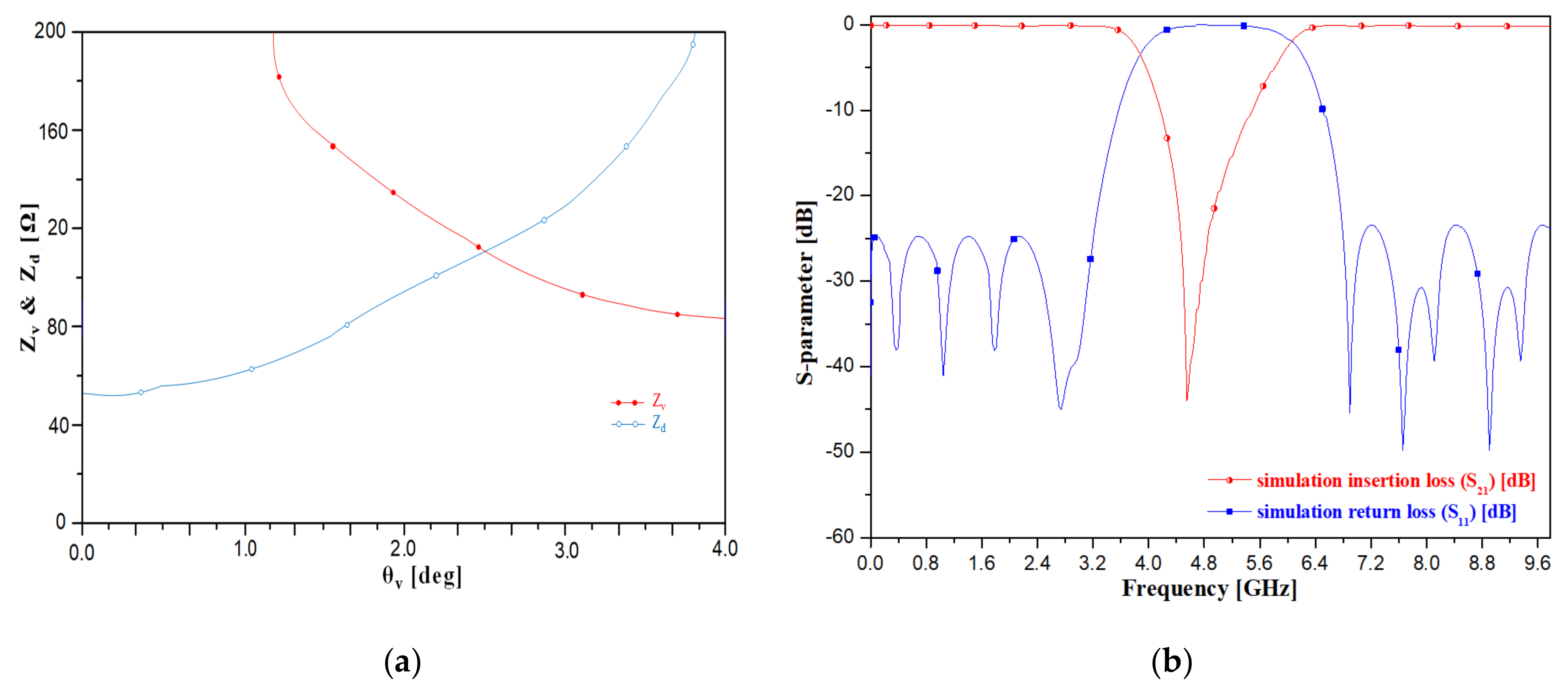
The value of θv must be more than 0° but less than 45° (2θv < θv = 90°). When θv is more than 45° (θv < 90°), Zd reaches infinity, as depicted in Figure 2a. As the shunt stub is −jZd cot θd = ∞, the T−shaped structure acts as an open stub. The values of Zv and Zd are 86.6 Ω and 75 Ω, and those of θv and θd are 30° and 45°, respectively.
Figure 2b depicts the simulation results for the band stop response between the first and second frequency bands using a T−shaped structure. The simulated insertion losses are 0.079 dB and 0.16 dB, and the simulated return losses are 24.8 dB and 23.4 dB at the first and second cut−off frequencies of 3.85 GH and 5.95 GHz in the BSF, respectively.
The calculated impedance and electrical length for the equivalent circuit are listed in Table 1.
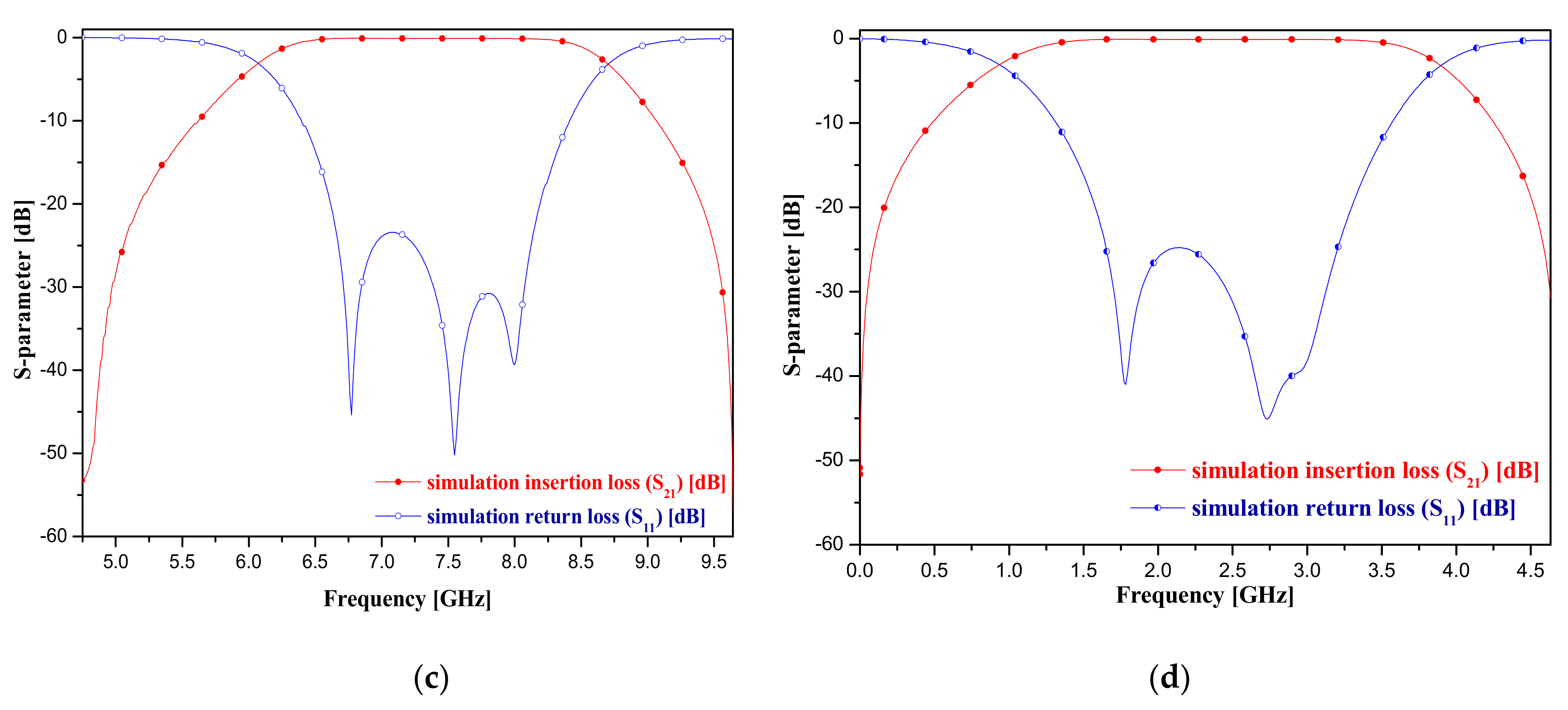
Figure 2c,d depicts the simulation results for the pass band of the first and second frequency ranges with folded short stubs and T–type short stubs. It is evident from the figure that the simulated first and second frequencies are 2.45 GHz (0.94–3.88 GHz) and 7.50 GHz (6.08–8.69 GHz) with bandwidths of 120% and 105%, respectively. The insertion losses of the first and second frequency ranges are 0.08 dB and 0.09 dB and the corresponding return losses are 24.8 dB and 23.4 dB, respectively.

3. Realization Process

3.1. Design and Fabrication

The structure of the proposed BPF can be adapted to a SIR structure whose size can be reduced, as depicted in Figure 3a. The figure depicts that the folded short stubs (Zs1 and Zs2) and T–type short stubs (ZT1, ZT2, and Zsm) are applied to the SIR structure, and the T–shaped open stubs (Zv and Zd) are BSF with T–shaped lines. The folded short stub is described as SIR with a λg/4 short stub, and the T–type short stub is expressed as the SIR with a λg/2 open stub.
Figure 3b depicts the designed BPF. From the figure, the values of ls1a, ls1b, ls2a, ls2b, and ls2c are 0.54 mm, 1.29 mm, 0.74, 0.495, and 0.45, respectively, and those of lT1, lT2, lsm, lv, ld1, and ld2 are 0.74 mm, 0.68 mm, 0.67 mm, 0.16 mm, and 0.14 mm, respectively. The values of ws1, ws2, wsm, wT1, wT2, wv, and wd are 0.52 mm, 0.16 mm, 0.14 mm, 0.65 mm, 0.17 mm, 0.2 mm, and 0.16 mm, respective, and those of l and h are 0.0708 λg × 0.0533 λg.
Figure 3c depicts the proposed BPF with T–shaped and folded–type SIR, which is fabricated on a Teflon substrate with a low dielectric of 2.54 and height 0.54 mm.

3.2. Experimental Results

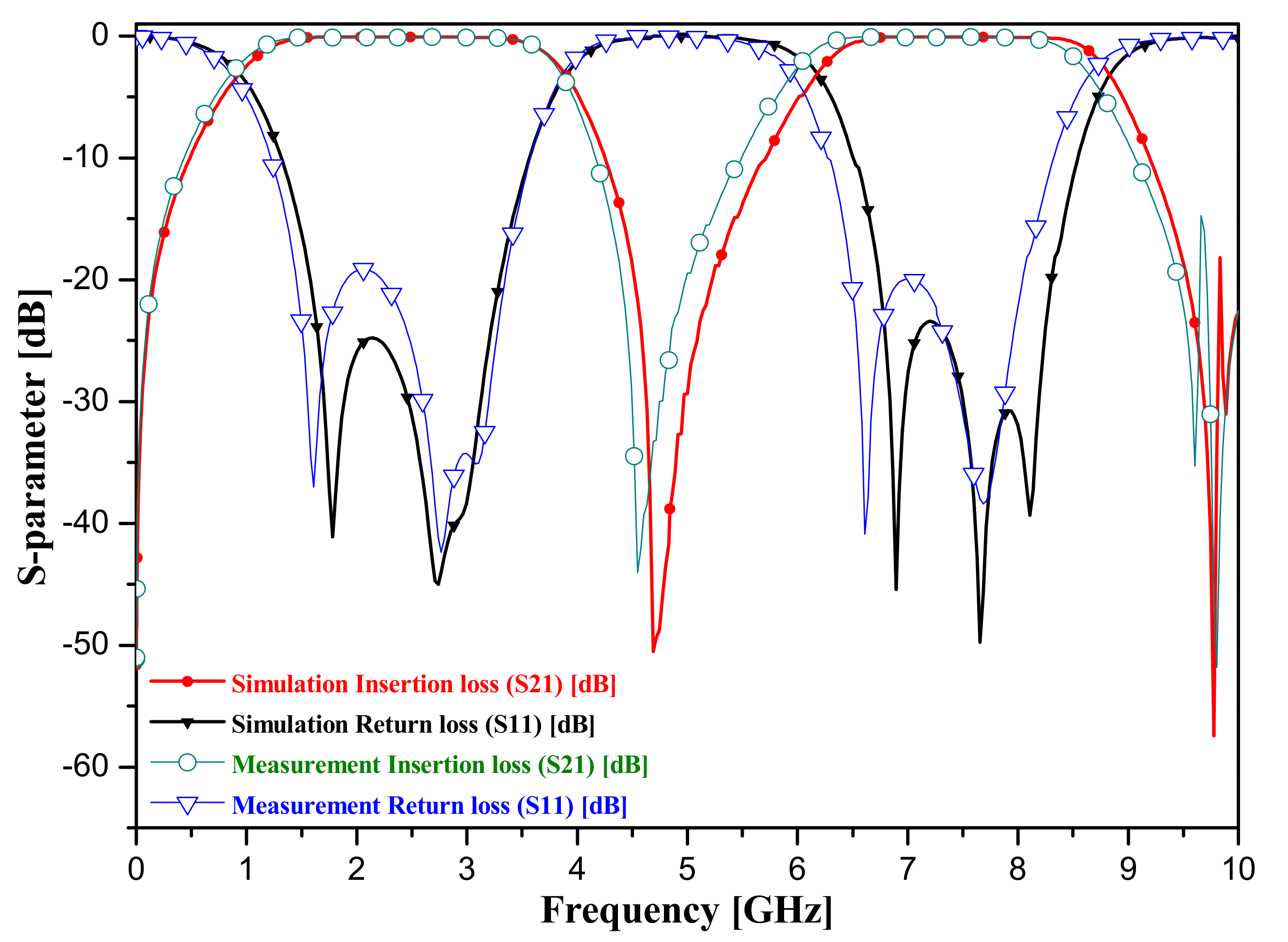
The simulation and measurement results obtained using the proposed BPF based on T–shaped and fold–type SIRs are depicted in Figure 4. From the figure, the experimental results are discussed the insertion loss (IL), return loss (RL), and bandwidth (Δ) as given by Equations (4)–(7) [30].
I L = 20 l o g T = 10 l o g 10 P o u t P i n d B
R L = 20 l o g Γ = 10 l o g 10 P o u t P i n d B
Δ = ω 1 ω 2 ω 0   f 1 f 2 f 0 × 100 %
where the T and Γ are coefficients of transmission and reflection, and the Pin and Pout are the power of incident and reflection, respectively. In addition, the ω1 and ω2 are angular frequencies of the lower and upper bands. Then, the ω0 is the center angular frequency.
The f1 and f2 are the frequency of the lower and upper bands. Then, the f0 is the center frequency.
The simulation results of the insertion and return losses for the first frequency pass band are 0.09 dB and 24.8 dB with a bandwidth of 120% at the center frequency of 2.45 GHz (0.94–3.88 GHz) and the same for the second frequency pass band is 0.10 dB and 27.3 dB with a bandwidth of 105% at the center frequency of 7.50 GHz (6.19–8.82 GHz) using the proposed BPF. In addition, the measurement result of the insertion and return losses for the first frequency pass band is 0.102 dB and 19.13 dB with a bandwidth of 120% at a center frequency of 2.43 GHz (0.85–3.85 GHz) and the same for the second frequency pass band are 0.103 dB and 19.96 dB with a bandwidth of 105% at a center frequency of 7.49 GHz (5.96–8.62 GHz) using the proposed BPF.

4. Discussion

The characteristic of the proposed BPF is to insert the T–shaped BSF into the BPF. Therefore, the designed BPF was able to obtain dual–band characteristics. Traditional BPFs simultaneously used the method of increasing mode, SLR method, and SIR method to increase bandwidth [2,3,4,5,6,7]. This method was able to adjust bandwidth and size by simultaneously adjusting the ratio of impedance and stub length. In particular, adjusting the length of the stub was able to create a transmission-zero [16]. Therefore, it was possible to design filters with excellent skirt phenomena. However, it is analyzed that these filters still increase in insertion loss and size [8,9,12]. The proposed BPF applied SLR and SIR at the same time. Thus, the filter can directly adjust the ratio of impedance to stub length. As a result, the filter was able to expand its bandwidth. The filter was also reduced in size using a folded structure.
Another attraction of the filter is the transmission–zero characteristics by adjusting the length (ld) of open stubs (see MT of Figure 1a) as shown in Figure 3b. This can achieve a sharp cut–off frequency characteristic. The proposed filter is an advantage of a wide bandwidth based on dual–mode. Table 2 lists a comparison of the proposed BPF with some others proposed previously. In this table, the bandwidths, insertion losses, and sizes are compared.
In the table, [20] is quarter–band BPF. Then, the center frequencies are 1.34 GHz, 2.2 GHz, 3.32 GHz, and 4.4 GHz, and the insertion losses are 1.32 dB, 1.26 dB, 2.23 dB, and 1.99 dB at first to firth center frequencies. In addition, the return losses are 16.37 dB, 24.63 dB, 17.39 dB, and 22.48 dB at first to firth center frequencies. The bandwidth is 5.22%, 3.63%, 4.2%, and 9.6% at first to firth center frequencies, respectively. The proposed BPF is lower insertion losses better than the comparison of BPFs, and the BPF is lower return losses less than others. Additionally, the size of a BPF is smaller more than other BPFs, and the bandwidth of a BPF is wider more than others.
The proposed filter is used for SLR and SIR together. Therefore, the filter is used to short–stub. The characteristic of Stub–filter is very sensitive to impedance [30]. If the filter had a narrow band, the impedance value would be very low. Therefore, the width of the stub will be very wide, and the size of the filter will be increased. If the filter has broadband, the impedance value will be very high. Thus, the filter will have a very narrow stub area. Therefore, it will be very difficult to produce filters.
When SLR and SIR are used together, both bandwidth and size can be adjusted by adjusting the ratio of impedance value to stub length [10,11].

5. Conclusions

In this paper, we proposed a compact dual–band band–pass filter (BPF) with short stubs and a T–shaped band–stop filter (BSF). The proposed BPF is adapted to a stepped impedance resonator (SIR) with a folded and T–type structure. The advantages of this BPF are its compact size, low insertion loss, and sharp cut–off frequency. The conventional stub BPF operates only in the single band. In addition, the existing dual–band BPFs are connected individually to the BPF and BSF, which makes the existing BPFs bulky. In contrast, the BPF proposed by us is integrated with the BSF using a single structure, thereby reducing the size of the new BPF. The overall size of the proposed BPF is 0.0708 λg × 0.0533 λg. The fabricated BPF has center frequencies of 2.43 GHz and 7.49 GHz, and the insertion loss is 0.102 dB and 0.103 dB at first and second center frequencies. Additionally, the return loss of first and second center frequencies for the proposed BPF is 19.13 dB and 19.96 dB, respectively. The bandwidth of the BPF is 120% and 105%, respectively. The proposed BPF can be mass–produced as a semiconductor owing to its planar structure. It can be applied to military mobile systems, medical systems, C–band weather radar systems (7.5 GHz), satellite communications (Satcom) (4–8 GHz), and industrial systems of wireless local area network (WLAN).

Author Contributions

Design and simulation; K.Y., analysis, and supervisor; K.K. All authors have read and agreed to the published version of the manuscript.

Funding

This research was supported by the Gachon Gil Medical Center(FRD2019-11-02(3)) and New Technology Development of AI based on High Value-added in the Ministry of SMEs and Startups (S2929853), respectively.

Informed Consent Statement

Not applicable.

Data Availability Statement

The data presented in this study are available upon request from the corresponding author. The data are not publicly available owing to privacy and ethical restrictions.

Acknowledgments

This fabrication and measurement was supported by RFIC Research Center (Director: Jong-Chul Lee and Nam-Young Kim) at Kwangwoon University.

Conflicts of Interest

The authors declare no conflict of interest.

References

  1. Zhang, J.; Liu, Q.; Zhang, D.-W.; Qu, Y. High Selectivity Single Wideband and Quad-Band HTS Filters Using Novel Quad-Mode Resonators with Self-Coupled Structure. IEEE Access 2021, 9, 103194–103203. [Google Scholar] [CrossRef]
  2. Rahman, M.; Park, J.-D. A Compact Tri-Band Bandpass Filter using Two Stub-Loaded Dual Mode Resonators. Prog. Electromagn. Res. M 2018, 64, 201–209. [Google Scholar] [CrossRef] [Green Version]
  3. Hsu, C.-Y.; Chen, C.-Y.; Chuang, H.-R. Microstrip Dual-Band Bandpass Filter Design with Closely Specified Passbands. IEEE Trans. Microw. Theory Tech. 2012, 61, 98–106. [Google Scholar] [CrossRef]
  4. Zhang, Z.C.; Chu, Q.X.; Chen, F.C. Compact dual-band bandpass filters using open-/short-circuited stub-loaded λ/4 resonators. IEEE Microw. Wirel. Compon. Lett. 2015, 25, 657–659. [Google Scholar] [CrossRef]
  5. Zhu, H.; Abbosh, A. Single- and Dual-Band Bandpass Filters Using Coupled Stepped-Impedance Resonators with Embedded Coupled-Lines. IEEE Microw. Wirel. Components Lett. 2016, 26, 675–677. [Google Scholar] [CrossRef]
  6. Liu, X.; Wu, W.; Ji, P.; Yuan, N. Design of Compact Dual-Passband Filters by Parasitic Passband with Controllable Passbands. IEEE Microw. Wirel. Components Lett. 2018, 28, 410–412. [Google Scholar] [CrossRef]
  7. Ren, B.; Ma, Z.; Liu, H.; Guan, X.; Wen, P.; Wang, X.; Masataka, O. Miniature dual-band bandpass filter using modified quarter-wavelength SIRs with controllable passbands. Electron. Lett. 2019, 55, 38–40. [Google Scholar] [CrossRef]
  8. Sami, A.; Rahman, M. A very Compact Quintuple Band Bandpass Filter Using Multimode Stub Loaded Resonator. Prog. Electromagn. Res. C 2019, 93, 211–222. [Google Scholar] [CrossRef] [Green Version]
  9. Wei, F.; Yu, J.H.; Zhang, C.Y.; Zeng, C.; Shi, X.W. Compact Balanced Dual-Band BPFs Based on Short and Open Stub Loaded Resonators with Wide Common-Mode Suppression. IEEE Trans. Circuits Syst. II Express Briefs 2020, 67, 3043–3047. [Google Scholar] [CrossRef]
  10. Chen, W.-Y.; Weng, M.-H.; Chang, S.-J. A New Tri-Band Bandpass Filter Based on Stub-Loaded Step-Impedance Resonator. IEEE Microw. Wirel. Compon. Lett. 2012, 22, 179–181. [Google Scholar] [CrossRef]
  11. Chen, W.-Y.; Su, Y.-H.; Kuan, H.; Chang, S.-J. Simple method to design a tri-band bandpass filter using asymmetric SIRs for GSM, WIMAX, and WLAN applications. Microw. Opt. Technol. Lett. 2011, 53, 1573–1576. [Google Scholar] [CrossRef]
  12. Li, J.; Chen, J.; Wang, J.; Shao, W.; Xue, Q.; Xue, L. Miniaturised microstrip bandpass filter using stepped impedance ring resonators. Electron. Lett. 2004, 40, 1420–1421. [Google Scholar] [CrossRef]
  13. Li, J. Multi-mode resonators with quad-/penta-/sext-mode resonant characteristics and their applications to bandpass filters. Int. J. RF Microw. Comput. Aided Eng. 2017, 27, e21072. [Google Scholar] [CrossRef]
  14. Sun, S.-J.; Su, T.; Deng, K.; Wu, B.; Liang, C.-H. Compact Microstrip Dual-Band Bandpass Filter Using a Novel Stub-Loaded Quad-Mode Resonator. IEEE Microw. Wirel. Compon. Lett. 2013, 23, 465–467. [Google Scholar] [CrossRef]
  15. Hejazi, Z.M. A fast design approach of compact microstrip multiband bandpass filters. Microw. Opt. Technol. Lett. 2012, 54, 1075–1079. [Google Scholar] [CrossRef]
  16. Wang, X.; Wang, J.; Zhu, L.; Choi, W.-W.; Wu, W. Compact Stripline Dual-Band Bandpass Filters with Controllable Frequency Ratio and High Selectivity Based on Self-Coupled Resonator. IEEE Trans. Microw. Theory Tech. 2019, 68, 102–110. [Google Scholar] [CrossRef]
  17. Xie, Y.; Chen, F.-C.; Li, Z. Design of Dual-Band Bandpass Filter With High Isolation and Wide Stopband. IEEE Access 2017, 5, 25602–25608. [Google Scholar] [CrossRef]
  18. Weng, M.-H.; Zheng, F.-Z.; Lai, H.-Z.; Liu, S.-K. Compact Ultra-Wideband Bandpass Filters Achieved by Using a Stub-Loaded Stepped Impedance Resonator. Electron 2020, 9, 209. [Google Scholar] [CrossRef] [Green Version]
  19. Karimi, G.; Salehi, A.; Javidan, F. Miniaturized (UWB) band pass filter using elliptical-ring multi-mode stub-loaded resonator (MM-SLR). Radioengineering 2018, 27, 732–737. [Google Scholar] [CrossRef]
  20. Gan, D.; He, S.; Dai, Z.; Wang, J. A quad-band bandpass filter using split-ring based on T-shaped stub-loaded step-impedance resonators. Microw. Opt. Technol. Lett. 2017, 59, 2098–2104. [Google Scholar] [CrossRef]
  21. Hsieh, L.-H.; Chang, K. Compact lowpass filter using stepped impedance hairpin resonator. Electron. Lett. 2001, 37, 899. [Google Scholar] [CrossRef]
  22. Ma, K.-X.; Ma, J.-G.; Do, M.; Yeo, K. Compact two-order bandpass filter with three finite zero points. Electron. Lett. 2005, 41, 846. [Google Scholar] [CrossRef]
  23. Zhu, L.; Devabhaktuni, V.; Wang, C.; Yu, M. A bandpass filter with adjustable bandwidth and predictable transmission zeros. Int. J. RF Microw. Comput. Eng. 2009, 20, 148–157. [Google Scholar] [CrossRef]
  24. Zakharov, A.; Rozenko, S.; Pinchuk, L.; Litvintsev, S. Microstrip Quazi-Elliptic Bandpass Filter with Two Pairs of Antiparallel Mixed-Coupled SIRs. IEEE Microw. Wirel. Components Lett. 2021, 31, 433–436. [Google Scholar] [CrossRef]
  25. Weng, M.-H.; Huang, C.-Y.; Dai, S.-W.; Yang, R.-Y. An Improved Stopband Dual-Band Filter Using Quad-Mode Stub-Loaded Resonators. Electron 2021, 10, 142. [Google Scholar] [CrossRef]
  26. Ren, B.; Liu, H.; Ma, Z.; Ohira, M.; Wen, P.; Wang, X.; Guan, X. Compact Dual-Band Differential Bandpass Filter Using Quadruple-Mode Stepped-Impedance Square Ring Loaded Resonators. IEEE Access 2018, 6, 21850–21858. [Google Scholar] [CrossRef]
  27. Zhou, L.H.; Chen, J.X. Differential dual-band bandpass filters with flexible frequency ratio using asymmetrical shunt branches for wideband CM suppression. IEEE Trans. Microw. Theory Techn. 2017, 65, 4606–4615. [Google Scholar] [CrossRef]
  28. Tang, J.; Liu, H.; Yang, Y. Compact Wide-Stopband Dual-Band Balanced Filter Using an Electromagnetically Coupled SIR Pair With Controllable Transmission Zeros and Bandwidths. IEEE Trans. Circuits Syst. II Express Briefs 2020, 67, 2357–2361. [Google Scholar] [CrossRef]
  29. Firmansyah, T.; Praptodiyono, S.; Wiryadinata, R.; Suhendar, S.; Wardoyo, S.; Alimuddin, A.; Chairunissa, C.; Alaydrus, M.; Wibisono, G. Dual-wideband band pass filter using folded cross-stub stepped impedance resonator. Microw. Opt. Technol. Lett. 2017, 59, 2929–2934. [Google Scholar] [CrossRef]
  30. Hong, J.-S.G.; Lancaster, M.J. Microstrip filters for RF/Microwave Applications; John Wiley & Sons: Hoboken, NJ, USA, 2004; Volume 167. [Google Scholar]
Figure 1. Equivalent circuit of the proposed BPF: (a) BPF and (b) J−inverter.
Electronics 10 01951 g001
Figure 2. Simulation results for response of filter frequency electrical length (a) impedance response of electrical length; (b) cut−off frequency of T−shaped line BSF; (c) BPF of first frequency response; and (d) BPF of second frequency response.
Electronics 10 01951 g002aElectronics 10 01951 g002b
Figure 3. Structure of the proposed BPF with T–shaped and folded type SIR (a) SIR structure, (b) layout (c) fabrication.
Electronics 10 01951 g003
Figure 4. Experimental results obtained using the proposed BPF.
Electronics 10 01951 g004
Table 1. Calculated electrical parameters.
ParameterValue [Ω]ParameterValue [Degree]
Zs189.2θs12.31
Zs2136θs27.07
ZT175.0θT12.82
ZT2134θT22.34
Zsm142θsm2.79
Zv86.6θv30
Zd75θd45
Table 2. Comparison of the proposed BPF with some previously proposed BPFs.
Ref [#]f0 [GHz]IL [dB]RL [dB]Δ [%]Size
g]
f01f02f03f01f02f03f01f02f03f01f02f03
this work2.437.49-0.1020.102-19.1319.96-120105-0.0708 × 0.0533
[2]1.572.403.450.411.391.9727.712.316.220.07.405.500.54 × 0.44
[4]2.45.80-1.351.97-17.015.0-4.633.60-0.39 × 0.25
[6]2.453.42-1.023.01----3.701.50-0.17 × 0.18
[7]2.365.83-1.101.60----5.803.10-0.16 × 0.18
[10]1.572.403.5016.01.502.309.0018.913.5N/AN/A-0.72 × 0.82
[11]1.803.505.201.201.802.005.0024.014.0N/AN/A-1.89 × 0.03
[13]2.093.525.451.180.540.8815.116.829.511.320.012.10.12 × 0.42
[20]1.342.203.321.321.262.2316.324.617.35.223.634.210.32 × 0.23
[26]2.605.80-1.102.10-15.015.0-10.43.60-0.26 × 0.34
[27]3.585.60-1.101.80-17.017.0-5.803.40-0.25 × 0.47
[28]1.753.64-2.001.10-N/AN/A-2.005.00-0.14 × 0.27
Publisher’s Note: MDPI stays neutral with regard to jurisdictional claims in published maps and institutional affiliations.