Article

Compact Size of an Interdigital Band-Pass Filter with Flexible Bandwidth and Low Insertion-Loss Using a Folded Spiral and Stepped Impedance Resonant Structure

1
Department of Biomedical Engineering, College of Medicine, Gachon University, 38-13, Dokjom-ro 3, Namdong-gu, Incheon 21565, Korea
2
Medical Devices R&D Center, Gachon University Gil Medical Center, 21, 774 Beon-Gil, Namdong-Daero, Namdong-gu, Incheon 21565, Korea
3
Department of Biomedical Engineering, College of Health Science, Gachon University, 191 Hambakmoero, Yeonsu-gu, Incheon 21936, Korea
4
Department of Health Sciences and Technology, Gachon Advanced Institute for Health Sciences and Technology (GAIHST), Gachon University, 38-13, 3 Dokjom-ro, Namdong-gu, Incheon 21565, Korea
*
Author to whom correspondence should be addressed.
Electronics 2021, 10(16), 2003; https://doi.org/10.3390/electronics10162003
Submission received: 27 July 2021 / Revised: 17 August 2021 / Accepted: 17 August 2021 / Published: 19 August 2021

Abstract

:
A conventional interdigital bandpass filter (BPF) is characterized by coupled and tapped lines and affords low insertion loss (IL) and easy fractional bandwidth (FBW) adjustment. However, the maximum FBW of the filter is limited to 30%, beyond that, its gap size increases, thereby rendering filter fabrication impractical on a standard printed circuit board. In addition, the filter size cannot be changed because it dictates the operational frequency of the filter. Hence, in this study, we propose a compact interdigital BPF based on a spiral and folded stepped impedance resonator (SIR), which affords low IL and excellent group delay. The spiral, folded structure facilitates drastic FBW adjustment: the center frequency and adjustable range of the FBW of the designed BPF are 800 MHz and 80 to 180%, respectively. Additionally, the proposed BPF can adjust the FBW by k-factor which can adjust from 80 to 180%. The insertion and return losses of the proposed filter are 0.043 dB and 17.1 dB, respectively, and the group delay is 0.098 ns. The total filter size is only 13.8 mm × 5.98 mm, which corresponds to a size reduction by factors of >2/8 relative to a conventional filter and 2.1 relative to the latest BPF design. The group delay difference between the BPF and other filters is 0.15 ns. In addition, the range of adjustable FBW for the filter is 1.36 times different than for other filters.

1. Introduction

The demand for portable wireless communication systems is continuously increasing due to the rapid development of fourth industrial revolution technology. The requirements for a portable wireless communication system are high performance, small size, and bandwidth securing function [1]. In wireless communication, a bandpass filter (BPF) is essential. BPF should be characterized by its high performance, as well as being small and light. In order to reduce the size, a substrate with a high dielectric constant must be used. However, a substrate with a high permittivity is expensive [2]. BPF should have low loss and sufficient bandwidth to meet system specifications [2]. Therefore, many studies are being conducted to obtain a BPF that is small in size, has low loss, and with sufficient bandwidth.
Recently, the compact size of a bandpass filter has increased to 180% of bandwidth [3,4]. In this regard, microstrip BPFs offer beneficial features such as frequency selection, low insertion loss (IL) and return loss (RL), and excellent coupled−line characteristics. In particular, the high performance interdigital BPF, which affords adjustable fractional bandwidth (FBW) through tapped−line control at the quarter−wavelength size, is superior to BPFs with coupled structures at harmonic operating frequencies [2,3,4,5,6,7,8]. However, the FBW of an interdigital BPF is limited to 30% [2], and the filter size cannot be reduced easily owing to its electrical length requirement of 90° and fixed operational frequency. Some techniques are necessary for BPF designs in terms of system integration, adjustable bandwidth, and various signal processing. Here, interdigital BPFs, based on coupled structures, can be used to enhance IL, RL, and frequency characteristic performances; consequently, many studies have focused on reducing the size of interdigital filters for practical applications. Some standard interdigital filters include T−type, folded−type, and spiral−type structures [9,10,11,12,13,14]. However, BPFs based on the interdigital or other coupled−structure shapes offer limited bandwidth applications. Thus, stepped impedance resonator (SIR), balun, and multi−mode resonator (MMR) structures have also been used for adjustable bandwidth and compact BPF designs [15,16,17,18,19,20,21,22]. Specifically, the relatively large−sized SIR structures afford low IL [22,23]. BPFs with adjustable bandwidth and high performance using the bridged T−coils have also been studied; however, such filters use a metal–insulator–metal (MIM) capacitor structure, which requires additional process masking and fabrication, thereby increasing manufacturing costs [24,25].
In this article, size reduction for the interdigital BPF is presented. The proposed BPF is designed according to the SIR structure, which affords low−loss operation and adjustable bandwidth, and the resulting filter is used for λg/4 square spiral−type and λg/4 square−type SIR short stubs. The newly developed BPF is small and has low losses owing to the SIR structure. Furthermore, the filter is additionally applied to analyze the effects of the tapped line on the feeding line (k-factor), with the potential to adjust the FBW.

2. Analysis of an Interdigital Bandpass Filter

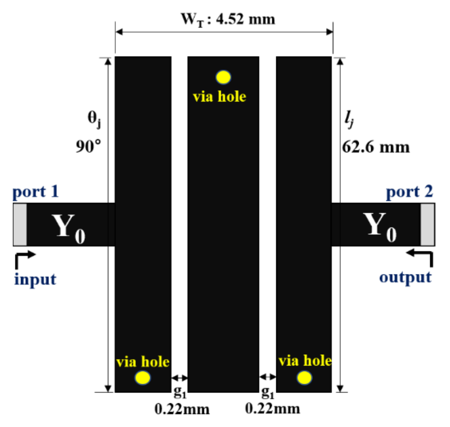
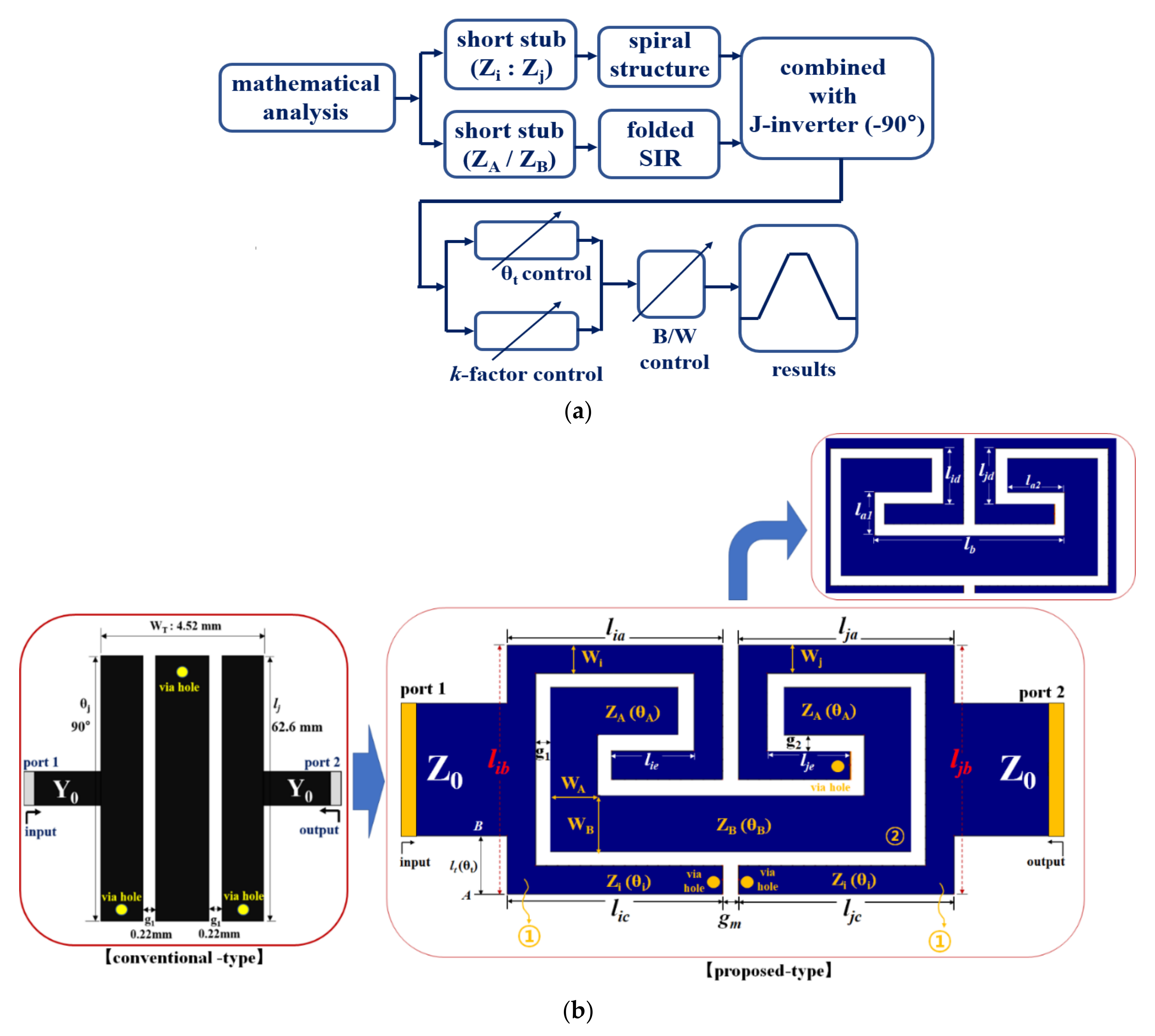
2.1. Conventional Bandpass Filter

The conventional interdigital BPF is composed of an λg/4 stub, a coupling structure, and a via hole, as shown in Figure 1 [2]; the dimensions of this BPF are a vertical length (lj) of 62.6 mm, a horizontal length (WT) of 4.52 mm (4.52 mm × 62.6 mm), and the stub electrical length (θj) is 90° (λg/4).
The coupling gap size (g1) is 0.22 mm. The FBW (Δ) of a conventional BPF can be increased by a maximum of 40%. If the coupling coefficient (M1) corresponding to the gap size (g1) increases, then the external quality factor (Qe) decreases, as given by Equations (1) and (2). Thus, the FBW increases when Qe decreases and g1 reduces, as shown in Figure 2.
The variable x is the g−parameter of the low−pass filter prototype [2]. Table 1 shows the gap size analysis for FBW variations. The FBW of 40% corresponds to a gap size of 0.12 mm.
M i ,   i + 1 = Δ x
Q e = x Δ
Such an interdigital BPF is impractical because the minimum gap size needed for printed circuit board (PCB) fabrication is 0.12 mm, and this size is extremely large for practical use. Moreover, fulfilment of the size criterion is more important than optimizing the gap size because the overall size of the BPF determines its operational frequency [2,26,27].

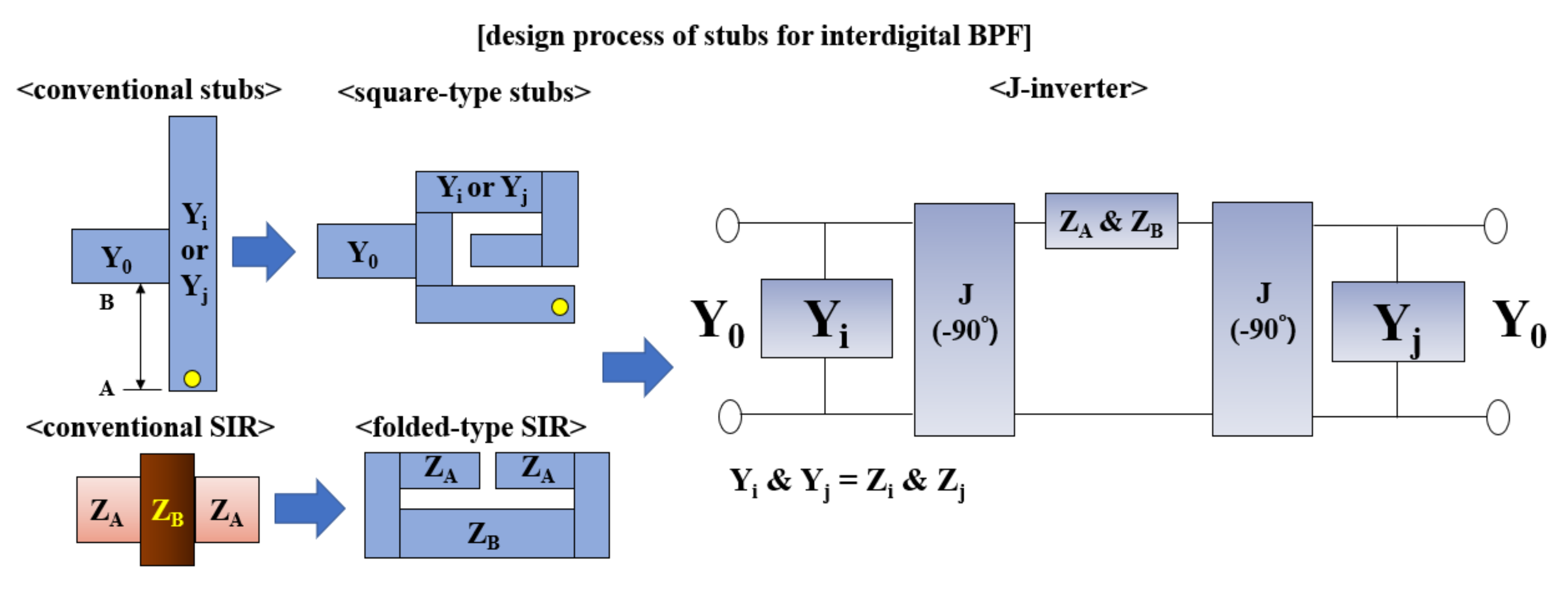
2.2. Proposed Bandpass Filter

The proposed filter presents the possibility of adjustable bandwidth through the variation in the feeding−line position using k-factor. In addition, the designed filter has a suggested size reduction and increased performance (low insertion loss and sharp frequency cut−off). Before the introduction, the flow chart and method characteristic of the proposed filter will be explained. The flowchart (block diagram) for the proposed interdigital BPF is shown in Figure 3a. Accordingly, the BPF first involves mathematical analysis; then, the spiral and folded SIR structures are applied to the resulting short stubs, which are combined with the J−inverter. Next, the bandwidth is adjusted based on the k-factor and θt to obtain the optimized BPF. The structure of the proposed BPF is introduced. The proposed size reduction in the interdigital BPF comprises λg/4 square spiral−type (①: see Figure 3b) and λg/4 square−type SIR (②) short stubs, as shown in Figure 3b.
In the spiral stubs (①: see Figure 3b), Zi and Zj represent the characteristic impedances, and θi and θj represent the electrical lengths of 90° each, respectively; wi and wj are the widths, and lia, lib, lic, lja, ljb, and ljc are the lengths of the structure. In the square-type SIR short stubs (②), la1, la2, and lb are the physical lengths; via holes of Ø 0.3 are placed at the ends of the stubs (①, ②).
The electrical length θx is the sum of θA and θB (θx = θA + θB), corresponding to the lengths of the stubs, and is 76.5°; θx is defined according to Equation (3), in which the 2 is a constant [2].
θ x = π 2 1 Δ 2
Parameters g1, g2, and gm are related to the coupling gaps between the stubs and correspond to the J−inverter design, as shown in Figure 4. Here, parameters Ji,j and Jj,i given by Equation (4) are both 0.0044.
In Equation (4), Ji=j,A=B refers to the inverter between θi (or θj) and θA (or θB), while g0, g1, and g2 denote the gap parameters of the resulting Chebyshev−type lowpass filter (LAR = 0.1 dB @ symmetric structure). Thus, g0, g1, and g2 are estimated as 1.0, 1.0316, and 1.1474, respectively [2,7].
J i = J , A = B 1 / Z 0 = g 0 2 g 1 g 0 · @ · J i = J A = B
The method to adjust the bandwidth and reduce the size of the proposed BPF is shown in Figure 4. From the figure, the existing stubs are redesigned into a spiral structure (for square−type) and a folded−SIR structure. The SIR is designed with an SIR structure that can satisfy the conditions of ZB < ZA and ZT = 0. At this time, the spiral structure and the folded−SIR structure are inserted into the resonant part (Yi and ZA and ZB) of the J−inverter. Then, the J−inverter (−90°) uses the coupling structure (g1, g2 in Figure 3b). Accordingly, the size of the BPF can be reduced with the square−type structure, while also utilizing the SIR structure [28]. Thus, the technique for producing a small size and an adjustable bandwidth forms the necessary mathematical analysis of the electrical parameters (k-factor). The physical performance is analyzed with the admittance inverter (J−inverter) and characteristic impedances of the short stubs with square spiral−type and square SIR−type structures, as shown in Equation (3).
To adjust the bandwidth, the BPF uses an SIR structure with open stubs. First, we need to create a resonance condition. By ignoring the discontinuous structure of the line, the impedance (1/ZT) is zero (1/ZT = 0), as shown in Equation (5).
1 Z T = j 1 Z A 2 k t a n θ B + t a n θ A k t a n θ B t a n θ A k 1 t a n 2 θ B 1 t a n 2 θ A 2 1 + k 2 t a n θ B t a n θ A = 0
At this time, when ZT = 0 (see Figure 3b), resonance that meets the condition for impedance matching occurs. Therefore, when designing the structure of the proposed filter, in order for ZT = 0, the actual structure must be ZB < ZA, and the length of ZA must be shorter than the length of ZB.
In the characteristic impedance case, k is the ratio of ZA to ZB, where ZA and ZB are 120.5 Ω and 85.7 Ω, respectively. Here, we can adjust the value of k accordingly, k (=ZA/ZB) = 1.41; therefore, to satisfy the resonance condition, 1/ZT should be zero. As the impedance ratio changes (reduces), if k is greater than 1, then the FBW exceeds 160%. When k is 1.3, this FBW is 180%, as shown in Figure 5. Thus, k is related to increasing the FBW and decreasing the losses. When the FBW is 180% (k = 1.3), the θA and θB are 0.714, 25°, and 15°, respectively. If tan (θT/2) is 10.8, then θT is 40.12°, as shown in Equation (6).
θ T = t a n 1 k = f n f 0
Here, fo and fn are the center frequency and nth frequency of the passband. To satisfy the resonance condition, Equation (7) must be satisfied so that k is not equal to 1 but 0 (i.e., k = Z A Z B = t a n θ A t a n θ B   @   k 1 ). It is possible to convert θT to lt and, by changing the lt value, the bandwidth can be changed while adjusting the k value. In this case, k = ZA/ZB.
t a n θ T 2 = 1 1 k k t a n θ B + t a n θ A
Therefore, the ratio of the ZA value to the ZB value is 180, and the k value becomes 1.3. At this time, if the lt value is changed in the lower direction with an interval of 0.05 mm, the k value is changed at an interval of 0.2. Therefore, when the value of k is 1.3, the bandwidth is 180%, as shown in Figure 5a. Moreover, if k is 1.0, 0.7, and 0.5, the bandwidth changes to 160%, 140%, and 120%, respectively. In addition, when k values are 0.3 and 0.1, the bandwidth changes to 100% and 80%, respectively. Figure 5b shows the results of changes for S21 and S11 corresponding to bandwidth from 80% to 180%, depending on the k-factor value. When the lt value of the filter is changed at 0.05 mm intervals, the bandwidth of S21 is changed from 80% to 180%. However, with a k value of 0.1 or less, the bandwidth change has a limit. Furthermore, from the k value of 1.3 or higher, the bandwidth does not increase anymore and remains fixed.
The reason for this is that if the k value is less than 0.1, the feeding−line of the filter reaches from point B to point A of the filter, and no further change can be made. Therefore, it is impossible to change the lt value. Moreover, if the k value exceeds 1.3, the bandwidth does not increase anymore and only the transmission−zero value increases. The reason for this is that as the ratio of the impedance (ZA//ZB) is changed, the bandwidth increase function is lost, and the resonance condition (ZT ≠ 0) is not met.
In relation to structural design (FBW = 180%), the characteristic impedances Zoe and Zoo of the even and odd modes, corresponding to the stubs and coupling structure, are expressed as Equations (8) and (9) and are estimated as 51.3 Ω and 48.7 Ω, respectively. Consequently, Z0T = 50 Ω upon obtaining the root of the product of Zoe and Zoo, as shown in Equation (10). At this time, the k0 value is a variable for the change in bandwidth, and the bandwidth changes according to the change in k0 value, and the impedance value also changes.
Z o e = k 0 1 + J i = j , A = B 1 k + J i = j , A = B 1 k 2
Z o o = k 0 1 J i = j , A = B 1 k + J i = j , A = B 1 k 2
Z o T = Z o e Z o o   Ω
The feed line locations for input and output can be expressed by Equations (11)–(14). Then, θt and lt denoting the physical and electrical lengths from point A to point B (Figure 3) can be estimated as 9.3° and 1.07 mm (FBW: 180%), respectively [2]. Furthermore, parameters λg and λ0, denoting the guided and free−space wavelengths, are estimated as 0.073 mm and 0.15 mm, respectively. Meanwhile, ε r e and ε r o are set as 4.68 and 3.76, respectively [2]. Parameters z (@ Zi, Zj, ZA, and ZB) and y denote the normalizations of the impedances and admittances, respectively, as viewed from point A (see Figure 3).
θ t = tan 1 1 J i = J i = j , A = B 1 J i = J i = j , A = B 2 1 z J i = J i = j , A = B 2
z = 1 1 + j y t a n d θ x   and   J i = J i = J i = j , A = B 1 / Z 0
l t = θ t 2 π λ g   mm
λ g = λ 0 ε r e ε r o 1 / 2   mm
The physical widths (gx, x+1) corresponding to g1, g2, and gm can be calculated from Equations (8) and (9); they are 0.22 mm each [2]. The permittivity εr (=2.54) and mutual capacitance C (0.04 pF) between the stub and ground plane of the substrate are estimated using Equations (15) and (16), respectively, and the angular frequency ω (=2πf0) is 800 MHz. The size of the complete BPF is 13.8 mm × 5.98 mm.
g x = 2 π t a n h 1 e x p π C x , x + 1 2 ε r @   x   =   1   to   2   and   x   +   1   =   m
C = t a n θ i i Z 0 T ω

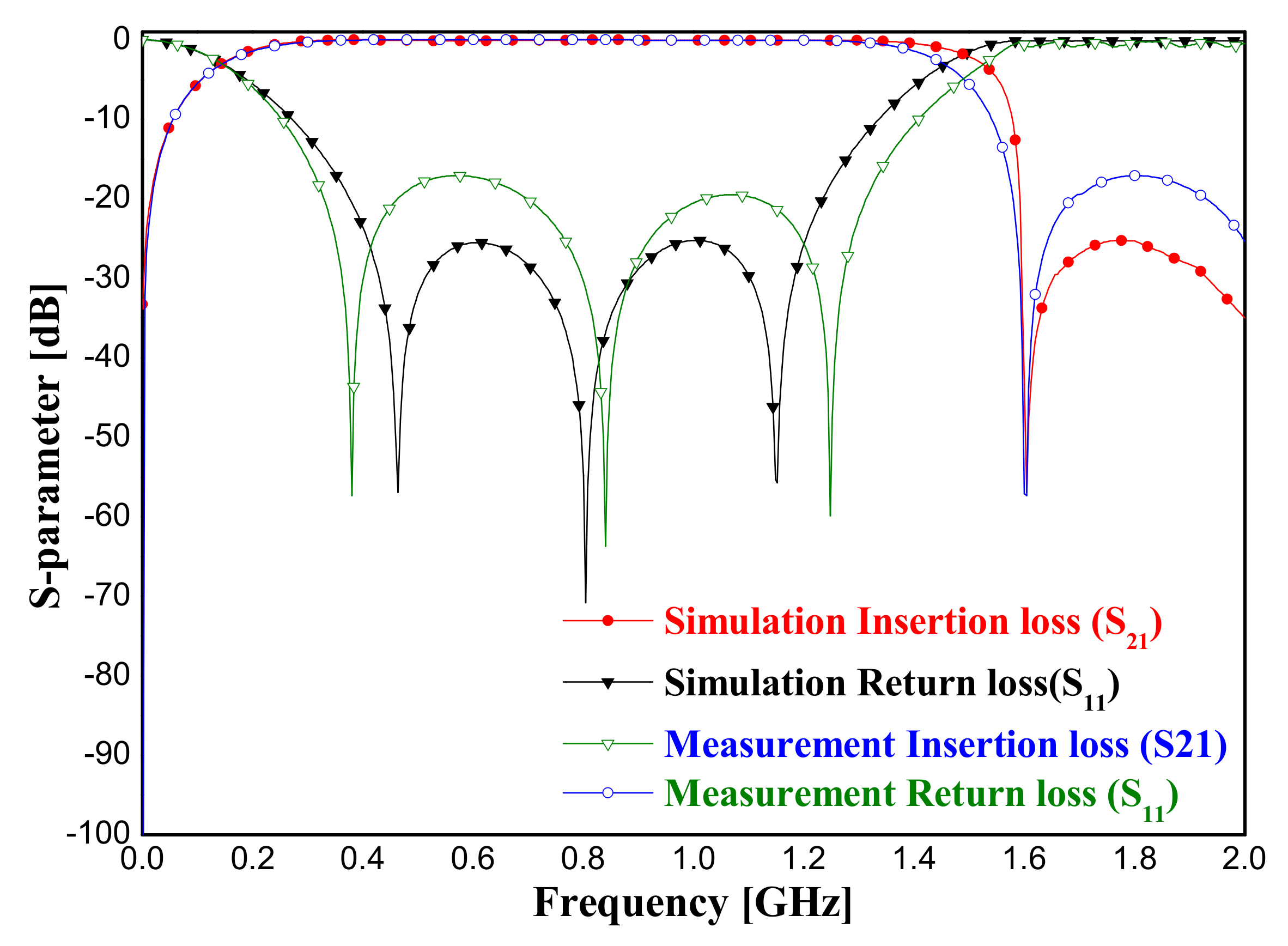
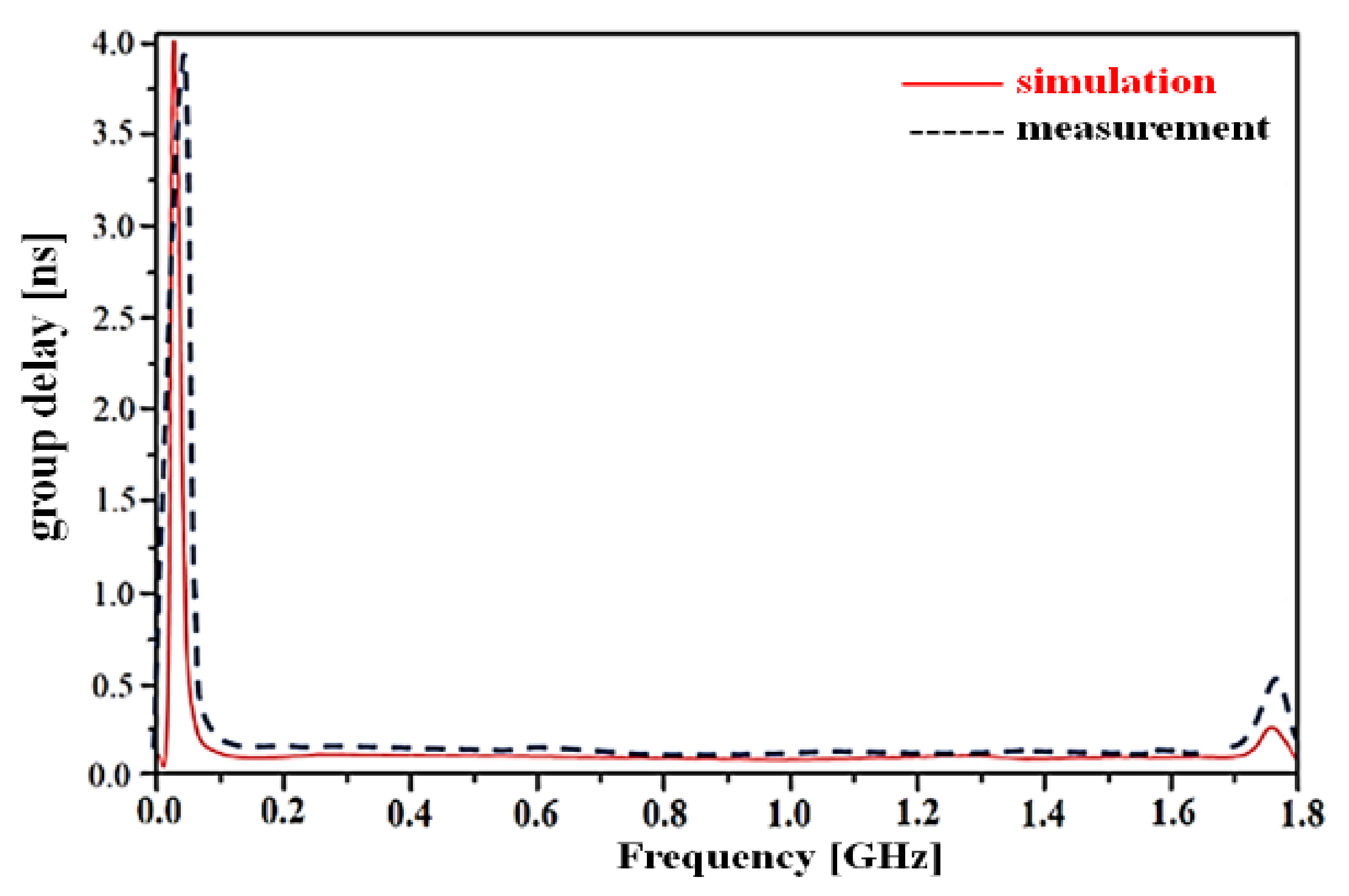
3. Fabrication and Experimental Results

The proposed BPF was fabricated, as shown in Figure 6a, using a low relative permittivity Teflon substrate (Taconic) with a dielectric constant of 2.54, a height of 0.54 mm, and a tangent loss (tan δ) of 0.002. We used the wet etching fabrication process with a film for negative development.
In the fabrication process, the film is developed through development, water, fixer, and dry processes through X−ray imaging, as shown in Figure 6b, to manufacture the filter. The substrate is put on the spin−quarter, then the photo resistor (TPR) solution is applied, and then the spin operation is performed. Then, after UV−patterning of the substrate and film, the TPR solution is sacrificed using TPR development. Finally, the production of the filter is completed through wet etching.
Figure 7 shows the experimental results of the proposed BPF, from which we note that the simulation results for the IL and RL are better than 0.03 dB and 25.5 dB, respectively, with an FBW of 180% at a center frequency of 800 MHz. Additionally, the measured results for the IL and RL are 0.043 dB and 17.1 dB, respectively, with an FBW of 180.3% at a center frequency of 804 MHz.
Figure 8 shows the simulated and measured results of the group delay of the proposed BPF, which are 0.086 ns and 0.098 ns, respectively, at a center frequency of 800 MHz. In Figure 7 and Figure 8, the simulation results were obtained using the zeland IE3D EM simulator. At this time, EM analysis was performed by dividing the cell per wavelength of the structure by 20 (@ highest frequency: 10 GHz).
For the measurement results in Figure 7, a vector network analyzer (VNA) was used. At this time, calibration was performed. The calibration process was performed in the order of termination, i.e., open, short, load, and thru (50 Ω). Finally, to express the simulation and measurement results, the Origin Pro simulator tool was used to edit the results for clarity.

4. Discussion

The proposed BPF exhibits FBW increment and size reduction by factors of 6 and 2/8, respectively, relative to the values of the structure in [2] (see Figure 1). The new BPF design allows an FBW increase from 80% to 180% by adjustment of the coupling (gi) and lt. In addition, the IL of the BPF can be controlled by adjusting lt [2]. Here, we note that, while the FBW of the conventional interdigital BPF can be sufficiently increased by adjusting lt and sj [2], it is practically limited to a maximum of 30% [2] because the maximum FBW of the J−inverter in the interdigital BPF is 30%. Therefore, the filter uses the SIR structure instead of a conventional resonator to increase FBW. The resonant condition of the SIR is 1/ZT ≠ 1 because of its discontinuous structure [28]; when 1/ZT = 1, this resonance condition cannot be satisfied.
In general, filters with via holes are known to generate parasitic energy losses [29]; however, the newly designed BPF has low losses and a planar structure because its feed line comprises a tapped−line structure that is directly connected to the stub with a spiral structure [2]. Parallel−coupled and edge−coupled BPFs are generally composed of coupled lines between the feed lines and stubs. The coupling structure heavily depends on the electric (E)−field energy and generates dielectric losses (coupling losses). However, as noted above, the feed line of the BPF is directly connected to the stub and has low coupling loss [30,31]. Therefore, it is possible to integrate the proposed interdigital BPF with other systems. If the BPF is designed for an FBW of 180%, the resulting size increase corresponds to a decrease in ZB [32], which means that k = 1; thus, the resonant condition no longer holds and the operational frequency decreases. In this new BPF, the SIR characteristics are excellent, owing to the presence of an attenuation pole [32]. Table 2 shows the comparison of the proposed BPF with other filters from previous studies [33,34,35,36,37,38].
The frequency bands in the table are applied to urban networks and LTE networks [39,40]. At this time, 800 MHz (791–821 MHz) is used in France, Germany, Italy, Morocco, and Tunisia, and 2.5–2.6 GHz and 1.8 GHz are used as LTE in Ghana, Canada, Colombia, Brazil, and south India (urban network). In particular, LTE and LTE−A are applied to 800 MHz–2600 GHz [a]. Therefore, the proposed filter is analyzed as being applicable for LTE equipment in each country.
The proposed BPF can thus be applied to mobile systems for smart factories, smart farms, and medical systems involving artificial intelligence (AI) and Internet of Things (IoT)−based applications in the fourth industrial revolution.

5. Conclusions

In this study, we used a stepped impedance resonator (SIR)−based design to fabricate a compact interdigital bandpass filter (BPF) that affords satisfactory insertion loss (IL), return loss (RL), and adjustable bandwidth performances. Conventional interdigital BPFs have a maximum fractional bandwidth (FBW) of 30%, with a size of 4.56 mm × 65.6 mm at a center frequency of 800 MHz; however, the designed BPF exhibits an FBW of 180%, with an overall size of 13.8 mm × 5.98 mm at 800 MHz. To reduce the size, we used a spiral design; moreover, the square folded SIR−type structure afforded FBW enhancement.
The proposed approach can be used to design BPFs whose impedances can be matched to the tuning parameters lt (k-factor); therefore, the BPF exhibits reduced IL and RL. In addition, the parameter lt, and hence the feed line position of the BPF, can be accurately estimated. The proposed BPF is smaller than conventional filters, with a size that is approximately 2/8 times smaller than conventional filters. The designed filter size is smaller by a factor of 2.1 compared to the latest BPF filters. The group delay difference between the proposed and conventional BPFs is at least 0.15 ns, and the FBW of the proposed BPF is 1.36 times that of the latest filters.
The proposed approach also enables the design of application specific BPFs, and the planar structure ensures easy system integrability for mass semiconductor fabrication, which additionally reduces production costs. Thus, the production of such BPFs can be easily scaled to address the problem of high demand.

Author Contributions

Design and simulation; K.Y., analysis, and supervisor; K.K. Both authors have read and agreed to the published version of the manuscript.

Funding

This work was supported by the Gachon University (2019-0369) and by the Gil Medical center (FRD2019-11-02(3)).

Institutional Review Board Statement

Not applicable.

Informed Consent Statement

Not applicable.

Data Availability Statement

The data presented in this study are available upon request from the corresponding author. The data are not publicly available owing to privacy and ethical restrictions.

Acknowledgments

This device was worked for fabrication and measurement at ProfJong−Chul Lee’s Laboratory and RFIC research Center (Director and Nam−Young Kim) at Kwangwoon University in Seoul, Republic of Korea, and the wet etching and metal coating work was supported by Prof Tae−Hyeon Lee at Gyeonggi University of Science and Technology in Siheung, Republic of Korea, respectively.

Conflicts of Interest

The authors declare no conflict of interest.

References

  1. Oke, A.; Fernandes, F.A.P. Innovations in teaching and learning: Exploring the perceptions of the education sector on the 4th industrial revolution (4IR). J. Open Innov. Technol. Mark. Complex. 2020, 6, 31. [Google Scholar] [CrossRef]
  2. Hong, J.S.; Lancaster, M.J. Microstrip Filters for RF/Microwave Applications; John Wiley & Sons Inc.: Hoboken, NJ, USA, 2001. [Google Scholar]
  3. Almorqi, S.; Shaman, H.; Alamoudi, A. Parallel−coupled stub−loaded resonator bandpass filter with ultra−wideband passband on multilayer liquid crystal polymer substrates. Int. J. Microw. Wirel. Technol. 2016, 8, 1183–1186. [Google Scholar] [CrossRef]
  4. Shaman, H.; Almorqi, S.; Al Amoudi, A. Ultra−wideband (UWB) Bandpass Filter with Cascaded Lowpass Filter on Multilayer Liquid−Crystal Polymer (LCP) Substrate. IETE J. Res. 2016, 62, 63–67. [Google Scholar] [CrossRef]
  5. Cristal, E.G.; Fankel, S. Hairpin−line and hybrid hairpin−line/half−wave parallel−coupled−line filters. IEEE Trans. Microw. Theory Tech. 1972, 20, 719–728. [Google Scholar] [CrossRef]
  6. Wong, J.S. Microstrip tapped−line filter design. IEEE Trans. Microw. Theory Tech. 1970, 27, 44–50. [Google Scholar] [CrossRef]
  7. Matthaei, G.L.; Young, L.T.; Jones, E.M. Microwave Filters, Impedance Matching Networks, and Coupling Structures; McGraw−Hil: New York, NY, USA, 1964. [Google Scholar]
  8. Mattaei, G.L. Interdigital band−pass filters. IEEE Trans. Microw. Theory Tech. 1962, 10, 479–491. [Google Scholar] [CrossRef]
  9. Xiang, K.R.; Chen, F.C. Compact microstrip bandpass filter with multispurious suppression using quarter−wavelength and half−wavelength uniform impedance resonators. IEEE Access 2018, 6, 20364–20370. [Google Scholar] [CrossRef]
  10. Moattari, A.M.; Karimi, G.H. Compact NB BPF is using modified slow wave resonator with wide upper stopband. Microw. Opt. Technol. Lett. 2016, 58, 616–619. [Google Scholar] [CrossRef]
  11. Singh, P.K.; Tiwary, A.K.; Gupta, N. Ultra−compact switchable microstrip band−pass filter−low−pass filter with improved characteristics. Microw. Opt. Technol. Lett. 2017, 59, 197–201. [Google Scholar] [CrossRef]
  12. Orellana, M.; Selga, J.; Vélez, P.; Sans, M.; Boria, V.E.; Martín, F. Design of capacitively loaded coupled−line bandpass filters with compact size and spurious suppression. IEEE Trans. Microw. Theory Tech. 2017, 65, 1235–1248. [Google Scholar] [CrossRef]
  13. Cidronali, A.; Collodi, G.; Maddio, S.; Pelosi, G.; Selleri, S. Quasi−elliptical band−pass filters based on compact spiral resonators for C−band applications. Microw. Opt. Technol. Lett. 2019, 61, 1983–1987. [Google Scholar] [CrossRef]
  14. Mu, Y.; Ma, Z.; Xu, D. A novel compact interdigital bandpass filter using multilayer cross−coupled folded quarter−wavelength resonators. IEEE Microw. Wirel. Compon. Lett. 2005, 15, 847–849. [Google Scholar]
  15. Feng, W.; Che, W.; Xue, Q. Compact−ultra−wideband bandpass filters with narrow notched bands based on a ring resonator. IET Microw. Antennas Propag. 2013, 7, 961–969. [Google Scholar] [CrossRef]
  16. Feng, W.; Che, W. Novel wideband differential bandpass filters based on T−shaped structure. IEEE Trans. Microw. Theory Tech. 2012, 60, 1560–1568. [Google Scholar] [CrossRef]
  17. Huang, F.; Wang, J.; Hong, J.; Wu, W. Wideband balun bandpass filter with broadside−coupled microstrip/slotline resonator structure. IET Electron. Lett. 2017, 53, 1320–1321. [Google Scholar] [CrossRef]
  18. Qiu, F.C.C.J.; Chen, Z.H.; Chu, Q.Q.X. Low insertion loss wideband bandpass filter with six transmission zeros. IET Electron. Lett. 2013, 49, 477–479. [Google Scholar]
  19. Zhou, C.X.; Guo, P.P.; Zhou, K.; Wu, W. Design of a compact UWB filter with high selectivity and superwide stopband. IEEE Microw. Wirel. Compon. Lett. 2017, 27, 636–638. [Google Scholar] [CrossRef]
  20. Lan, S.W.; Weng, M.H.; Hung, C.Y.; Chang, S.J. Design of a compact ultra−wideband bandpass filter with an extremely broad stopband region. IEEE Microw. Wirel. Compon. Lett. 2016, 26, 392–394. [Google Scholar] [CrossRef]
  21. Sheikhi, A.; Alipour, A.; Mir, A. Design and fabrication of an ultra−wide stopband compact bandpass filter. IEEE Trans. Circuits Syst. II Express Briefs 2020, 7, 265–269. [Google Scholar] [CrossRef]
  22. Huang, C.C.; Fang, W.T.; Lin, Y.S. Miniaturization of broadband stub bandpass filters using bridged−T coils. IEEE Access 2018, 6, 20164–20173. [Google Scholar] [CrossRef]
  23. Gomez−Garcia, R.; Alonso, J.I. Design of sharp rejection and low−loss wide−band planar filter using signal−interference techniques. Microw. Wirel. Compon. Lett. 2005, 15, 530–532. [Google Scholar] [CrossRef]
  24. Suh, B.; Lee, H.; Kim, S.; Jeon, S. A D−band multiplierbased OOK transceiver with supplementary transistor modeling in 65-nm bulk CMOS technology. IEEE Access 2019, 7, 7783–7793. [Google Scholar] [CrossRef]
  25. Han, I.S.; Kwon, H.M.; Kwon, S.K.; Choi, W.I.; Lim, S.; Kim, J.S. A study of dielectric relaxation and capacitance matching of Al2O3/HfO2/Al2O3 MIM capacitors. IEEE Electron. Device Lett. 2013, 34, 1223–1225. [Google Scholar] [CrossRef]
  26. Yun, T.S.; Hong, T.U.; Lee, B.; Choi, J.J.; Kim, J.Y.; Kim, K.B.; Lee, J.C. New band−pass filter design with tapped−line using J/K−inverter. Microw. Opt. Technol. Lett. 2007, 49, 1253–1256. [Google Scholar] [CrossRef]
  27. Yoon, K.C.; Lee, J.C. Design of a compact wide−bandwidth band−pass filter using a parallel−coupled structure. Microw. Opt. Technol. Lett. 2012, 54, 2581–2584. [Google Scholar] [CrossRef]
  28. Makimoto, M.; Yamashita, S. Microwave Resonators and Filters for Wireless Communication, Theory, Design and Application; Springer: Berlin/Heidelberg, Germany, 1944. [Google Scholar]
  29. Laermans, E.; de Geest, J.; de Zutter, D.; Olyslager, F.; Sercu, S.; Morlion, D. Modeling Differential via Holes. IEEE Trans. Adv. Packag. 2001, 24, 357–363. [Google Scholar] [CrossRef]
  30. Chang, K.; Martin, S.; Wang, F.; Klein, J.L. On the study of microstrip ring and varactor−tuned ring circuits. IEEE Trans. Microw. Theory Tech. 1987, 35, 1288–1295. [Google Scholar] [CrossRef]
  31. Zhu, L.; Wu, K. Line−to−ring coupling circuit model and its parametric effects for optimized design of microstrip ring circuits and antennas. In Proceedings of the 1997 IEEE MTT−S International Microwave Symposium Digest, Denver, CO, USA, 8–13 June 1997; pp. 289–292. [Google Scholar]
  32. Shzng, Z.; Guo, X.; Cao, B.; Wei, B.; Zhang, X.; Heng, Y.; Suo, G.; Song, X. Design of a superconducting ultra−wideband (UWB) bandpass filter with sharp rejection skirts and miniaturized size. IEEE Microw. Wirel. Compon. Lett. 2013, 23, 72–74. [Google Scholar]
  33. La, D.S.; Guan, X.; Li, H.C.; Li, Y.Y.; Guo, J.W. Design of broadband band−pass filter with cross−coupled line structure. Int. J. Antennas Propag. 2020, 2020, 5257325. [Google Scholar] [CrossRef]
  34. Peng, B.; Li, S.; Zhu, J.; Zhang, Q.; Deng, L.; Zeng, Q.; Gao, Y. Compact quad−mode bandpass filter based on Quad−Mode DGS Resonator. IEEE Microw. Wirel. Compon. Lett. 2016, 26, 234–236. [Google Scholar] [CrossRef]
  35. Yang, L.; Zhu, L.; Zhang, R.; Wang, J.; Choi, W.; Tam, K.; Gómez−García, R. Novel multilayered ultra−broadband bandpass filters on high−impedance slotline resonators. IEEE Trans. Microw. Theory Tech. 2019, 67, 129–138. [Google Scholar] [CrossRef]
  36. Hao, H.; Ni, X. Wideband filtering power divider with wide rejection bandwidth and isolation. IET Electron. Lett. 2019, 55, 395–396. [Google Scholar] [CrossRef]
  37. Sans, M.; Selga, J.; Vélez, P.; Bonache, J.; Rodríguez, A.; Boria, V.E.; Martín, F. Compact wideband balanced bandpass filters with very broad common−mode and differential−mode stopbands. IEEE Trans. Microw. Theory Tech. 2018, 66, 737–750. [Google Scholar] [CrossRef]
  38. Moradi, B.; Martinez−Iranzo, U.; Garcia−Garcia, J. Multimode ultra−wideband filters by using a grounded open ring resonator. Microw. Opt. Technol. Lett. 2016, 58, 2001–2004. [Google Scholar] [CrossRef] [Green Version]
  39. Cavalcanti, B.J.; Cavalcante, G.A. A hybrid path loss prediction model based on artificial neural networks using empirical models for LTE and LTE−A at 800MHz and 2600 MHz. J. Microw. Optoelectron. Electromagn. Appl. 2017, 16, 708–722. [Google Scholar] [CrossRef] [Green Version]
  40. Cheerla, A.; Ratnam, D.V.; Borra, H.S. Neural network−based path loss model for cellular mobile networks at 800 and 1800 MHz bands. Int. J. Electron. Commun. 2018, 94, 179–186. [Google Scholar] [CrossRef]
Figure 1. Conventional interdigital BPF layout.
Electronics 10 02003 g001
Figure 2. Determination of the gap size according to (a) external quality factor and (b) coupling coefficient.
Electronics 10 02003 g002
Figure 3. Structure of the proposed small−sized interdigital BPF using the spiral and SIR techniques: (a) flowchart (block diagram) (b) filter structure.
Electronics 10 02003 g003
Figure 4. Equivalent circuit of the proposed BPF.
Electronics 10 02003 g004
Figure 5. Variation in the FBW of the SIR structure in terms of (a) k-value, (b) parameter S21, and (c) parameter S11.
Electronics 10 02003 g005aElectronics 10 02003 g005b
Figure 6. Fabrication of a new bandpass filter: (a) photograph and (b) fabrication process (wet etching).
Electronics 10 02003 g006
Figure 7. Simulated and measured insertion and return losses.
Electronics 10 02003 g007
Figure 8. Simulated and measured group delays of the designed BPF.
Electronics 10 02003 g008
Table 1. Variation in FBW as a function of BPF gap size.
Δ [%]5.0%10%20%30%40%
g1 [mm]0.200.180.160.140.12
Table 2. Comparison of the sizes and FBWs of BPFs.
Ref [#]fo [GHz]FBW [%]IL [dB]RL [dB]Size [mm2]Structure
This work0.801800.04317.113.8 × 5.98interdigital BPF
[33]1.8042.00.7015.023.12 × 22.76stub−coupled line
[34]2.4532.02.3010.027.0 × 27.0SIR with DGS
[35]2.001330.9018.240.96 × 12.33slot−line SIR
[36]2.3555.346.5 × 35.0parallel coupled line
[37]1.8055.41.0011.551.5 × 48.2interdigital−SIR
[38]2.561280.5020.021.5 × 10.0multimode resonator
Publisher’s Note: MDPI stays neutral with regard to jurisdictional claims in published maps and institutional affiliations.

