Article

An Artificial Magnetic Conductor-Based Wideband Circularly Polarized Antenna with Low-Profile and Enhanced Gain

Key Laboratory of Ministry of Education of Design and Electromagnetic Compatibility of High Speed Electronic Systems, Shanghai Jiao Tong University, Shanghai 200240, China
*
Author to whom correspondence should be addressed.
Electronics 2021, 10(17), 2121; https://doi.org/10.3390/electronics10172121
Submission received: 5 August 2021 / Revised: 26 August 2021 / Accepted: 27 August 2021 / Published: 31 August 2021
(This article belongs to the Section Microwave and Wireless Communications)

Abstract

:
A broadband circularly polarized (CP) antenna with enhanced gain and low profile is proposed. Two identical dipoles with full wavelength are placed orthogonally to generate radiation waves with equal amplitude and orthogonal polarization. The arms of the dipoles are designed as stepped patches to enlarge the impedance matching bandwidth and axial ratio (AR) bandwidth. Crossed-dipoles with full wavelength are utilized as the main radiators to provide a wide operating bandwidth and enhanced gain, and an artificial magnetic conductor (AMC) structure is introduced as the reflector to reduce the profile of the whole antenna. Due to the introduction of the AMC structure, the antenna profile is reduced from 12.8 to 6.9 mm, that is, reduced to 0.14 λ 0 (where λ 0 denotes the wavelength corresponding to the center frequency of the passband, 4.0–8.5 GHz). A simulation and experiment were carried out to verify the performance of the proposed antenna. Experimental results showed that the antenna realized an impedance bandwidth of 74%, an AR bandwidth of 67.7%, a peak gain of 12.1 dBic, and an average gain of 10.69 dBic.

1. Introduction

Circularly polarized antennas have been widely used in communication systems because of their advantages of resisting multipath distortion, polarization mismatch losses, and Faraday rotation effects. Traditional microstrip CP antennas usually have a narrow impedance matching bandwidth and an AR bandwidth. With the development of modern communication technology, the wideband CP antenna has become a popular research topic in recent years. Several means have been utilized to improve the impedance matching and AR bandwidths of microstrip CP antennas, such as microstrip antennas based on a reactive impedance surface [1], stacked patches [2], antenna arrays with a sequential feeding network [3], and multilayered structures [4]. However, these broadband designs either increase the design difficulty of the radiator or introduce a complex feeding network. In contrast to microstrip CP antennas, CP antennas based on a crossed dipole have inherent broadband characteristics. In recent years, several techniques have been proposed to improve the operating bandwidth of crossed-dipole CP antennas, such as crossed dipoles with parasitic elements [5,6,7], crossed dipoles with wide open ends [8,9], and cavity-backed crossed dipoles [6,9,10]. Despite significant improvements in bandwidth, the antennas proposed above maintain a typical profile of around 0.25 λ 0 . The profile of the cavity-backed antenna is even higher; for example, the antenna profiles in [6,7] are as high as 0.28 λ 0 and 0.27 λ 0 respectively. However, a high profile is not conducive to the practical application of the antenna.
In recent years, metasurfaces have been widely used in the design of antennas [11,12]. Because they allow the antenna profile to be reduced, AMC reflectors have been widely applied to linear polarized antennas [13,14], dual-polarized antennas [15,16], CP antennas [17,18,19], and polarization-reconfigurable antennas [20,21]. In [13,14], AMCs were positioned underneath radiators, and the profiles were reduced to 0.05 λ 0 and 0.08 λ 0 , respectively. A dual-wideband low-profile CP antenna was realized in [18] by loading the AMC surface under the crossed dipole. Impedance matching bandwidths of 40% and 49.5%, and 3 dB AR bandwidths of 19.3% and 33.8%, were obtained, for the lower and upper bands, respectively. In addition, the antenna profile was reduced to 0.16 λ 0 due to the introduction of the AMC. A crossed dipole-based CP antenna with a low profile was proposed in [19]; an impedance matching bandwidth of 66.3% and a 3 dB AR bandwidth of 44.7% were achieved, and the profile was reduced to 0.12 λ 0 . In addition, in [20], a reconfigurable antenna with an overlapped BW of 53.9% and a profile of 0.1 λ 0 was achieved with an AMC ground plane. A low-profile polarization-reconfigurable dipole antenna was proposed in reference [21] based on an AMC structure. An impedance matching bandwidth of 19.6% and a 3 dB AR bandwidth of 15.5% were achieved, and the profile was reduced to 0.056 λ 0 .
It is well known that a full-wavelength dipole has higher gain than the commonly used half-wavelength dipole due to its electrically larger size. Nevertheless, full-wavelength dipoles are rarely used in practice because of impedance matching difficulties. In recent years, some efforts have been made to promote the application of full-wavelength dipoles. A wideband center-fed full-wavelength dipole was proposed in [22], which realized an impedance matching bandwidth of 32%. A compact dual-polarized full-wavelength dipole antenna was proposed in [23], which has a significantly wider bandwidth of 78%. These studies demonstrate that, if the impedance matching issue can be solved, the full-wavelength dipoles potentially exhibit higher directivity and wider bandwidth compared with half-wavelength dipoles. Rather than feeding a single full-wavelength dipole, four full-wavelength dipoles are connected in parallel and matched with a standard coaxial cable in [24]. This method not only solves the impedance matching problem but also reduces the antenna elements for the same gain, which assists in the production of a low-cost and high-efficiency antenna array.
In this study, rather than utilizing half-wavelength dipoles, two identical full-wavelength dipoles were adopted to construct a CP antenna. Moreover, a broadband AMC reflector was introduced to reduce the antenna profile. The profile of the proposed antenna was reduced while the wide operating bandwidth was maintained. An antenna prototype was fabricated and measured. Compared with other related designs, the proposed antenna has obvious advantages in terms of the gain and operating bandwidth. In addition, the designed antenna achieves higher gain without employing antenna arrays and complex feeding networks. The antenna’s low-profile characteristics can reduce the vertical space needed and the air resistance in outdoor applications. The proposed antenna provides an example of the design of a broadband CP antenna with enhanced gain and low profile.

2. Antenna Design

The dipole antenna is one of the most widely used antennas because of its inherent broadband properties. Modern communication systems require wider bandwidth, and the crossed-dipole structure is a promising scheme for realizing wideband circularly polarized radiation. In the following section, a CP antenna is presented based on full-wavelength dipoles to demonstrate their wide bandwidth and high-gain potential.

2.1. Impedance Matching

As Figure 1 shows, the resistance and reactance of a traditional dipole with narrow arms change dramatically near the full wave region, which causes difficulty in impedance matching. After broadening the arm width, both the real part and the imaginary part of the input impedance are reduced significantly near the full wave region. Circularly polarized radiation requires two orthogonal fields with equal amplitudes and quadrature phases, which can be realized by introducing a 90° phase delay line between the two orthogonal dipoles. This is shown in the third structure in Figure 1, and more details are provided in later sections. The connection line provides the phase difference needed for CP radiation, and also realizes the parallel connection of the dipoles and improves the impedance matching characteristics. The blue curve in Figure 1 demonstrates that the crossed dipole can be easily matched to a standard coaxial line near the full wave region.

2.2. Evolution of the Dipole

The following section demonstrates the evolution process of a CP crossed-dipole antenna with a wide AR band. The side view of the antenna is shown in Figure 2a. To achieve forward radiation with high gain, a metal reflector is normally introduced at the distance of 0.25 λ 0 from the radiator. The inner conductor of the coaxial cable is connected to the upper patch, and the outer conductor is connected to the lower patch and the metal plate. Figure 2b–f shows the evolution of the crossed-dipole radiator. Starting from a crossed-dipole with narrow arms, the details of the connecting part are shown in the thumbnail. The dipole arms on the same side are connected by a phase delay line with a length of 0.25 λ 0 .
As shown in Figure 3, Ant.1 has poor performance. With the widening of the dipole arm, the impedance matching bandwidth is significantly improved. However, the AR bandwidth is still not good at this stage. To reduce the AR within the band, the ends of the arms are widened to obtain dipole 3. As shown in Figure 3, the reflection coefficient slightly changes while the AR values at lower frequencies are reduced significantly. It can be found that the AR values are greatly reduced in a broadband and the reflection coefficient is also slightly reduced by adding more steps to the arms. To further improve the impedance matching performance of the antenna, a corner cut is introduced, as shown in Figure 2f. Although a part of the operating bandwidth (below 4.0 GHz) is sacrificed, the reflection coefficient of the remainder is greatly improved. Subsequently, the AR values within the band are further reduced, as shown in Figure 3. In addition, because the length of the phase delay line remains constant, the minimum AR values are obtained at 6.6 GHz for all crossed-dipole antennas shown in Figure 2. With the evolution of the dipole structure, the AR bandwidth is gradually expanded around the central frequency at 6.6 GHz.

2.3. AMC Design

A crossed-dipole antenna with a broadband |S11| and AR bandwidth was obtained after structural optimization. The following discussion focuses on reducing the profile of the antenna. As is well known, a metallic reflector produces a 180° reflection phase. Consequently, the traditional metallic reflector should be placed around 0.25 λ 0 from the radiator to remove its back lobe and to construct a unidirectional forward pattern with higher directivity. However, an AMC reflector has a reflection phase of nearly 0° at the central frequency. In addition, the operating band of an AMC reflector is defined as the frequency range of the reflection phase between +90° and −90°. In contrast to the metallic reflector, an AMC reflector can be placed close to the radiator to reduce the profile of the whole antenna. For this reason, the AMC structure has aroused widespread interest among researchers in recent years.
A polarization-independent AMC with a wide bandwidth is introduced underneath the crossed dipole. The element of the AMC is shown in Figure 4a. The reflection phase was simulated with CST microwave studio. In the simulation, the boundary conditions “Unit Cell” were used for the side walls, as labeled in the figure. The AMC unit cell consists of three layers: a square patch on the top, a substrate in the middle, and a metal plate on the bottom. The substrate is made of Rogers 5880 with a dielectric constant of 2.2, relative permeability of 1, loss tangent of 0.0009, and thickness of 3.175 mm. The side length of the unit cell is 7.6 mm and the side length of the square patch is 6.6 mm. The simulated reflection phase is shown in Figure 4b. The AMC structure reflects the normally incident wave with a 0° reflection phase at 6.2 GHz and yields a bandwidth of 4.5–7.5 GHz with a reflection phase between ±90°. The influence of the AMC size on the antenna performance is discussed in the next section.
The side view of the comparison of the reference antenna and the proposed antenna is shown in Figure 5a. The crossed dipole is printed on the front and back surfaces of the upper substrate for each antenna, and the AMC reflector with a square patch unit cell is printed on the lower substrate of the proposed antenna. For the reference antenna without the AMC, the metal ground is placed 12.8 mm from the crossed dipole. It is worth noting that the profile is reduced from 12.8 to 6.9 mm after loading the AMC reflector. The upper substrate is made of Rogers RO4350B with a relative permittivity of 3.48, relative permeability of 1, loss tangent of 0.0027, and thickness of 0.762 mm. An air gap with a thickness of 3 mm is sandwiched between the two substrates. The lower substrate is made of Rogers 5880, with parameters given in the AMC design section. A single port coaxial feedline is adopted in this configuration without a complex feeding network. The inner conductor of the coaxial cable is connected to the upper patch, and the outer conductor is connected to the lower patch and the metal plate. Four nylon columns are installed near the edge of the upper substrate to maintain the mechanical stability of the antenna, which was verified to have little effect on antenna performance.
As shown in Figure 5b, two orthogonal dipole arms are printed on the top surface of the upper substrate (marked with black), and the other pair is located on the bottom surface (marked with gray). The total length of the dipole arm is close to half a wavelength and the width of the arm is sequentially widened. In this manner, the impedance matching bandwidth and AR bandwidth are improved. The arms on the same side are connected by a phase delay line with a length of 0.25 λ 0 . The top and bottom patches are identical but rotated 180° around the feeding point, and are connected to the inner and outer conductors of the feed line, respectively. Therefore, orthogonal radiations with an equal amplitude and a 90° phase difference are generated and the CP radiation can be realized. The design parameters are as follows: p m = 6.6   mm ,   l s u b 1 = 70   mm ,   l s u b 2 = 80   mm , g m = 1.0   mm , l c c = 17   mm , w c c = 5.8   mm , l 1 = 8   mm , l 2 = 9   mm , l 3 = 16   mm , l 4 = 17   mm , l 5 = 25   mm , w 1 = 11   mm , w 2 = 13   mm , w 3 = 15   mm , w 4 = 20   mm , w 5 = 26   mm , the radius of phase delay line   r c = 2.4   mm , and the width of phase delay line   w c = 0.4   mm .

2.4. Key Parameter Study

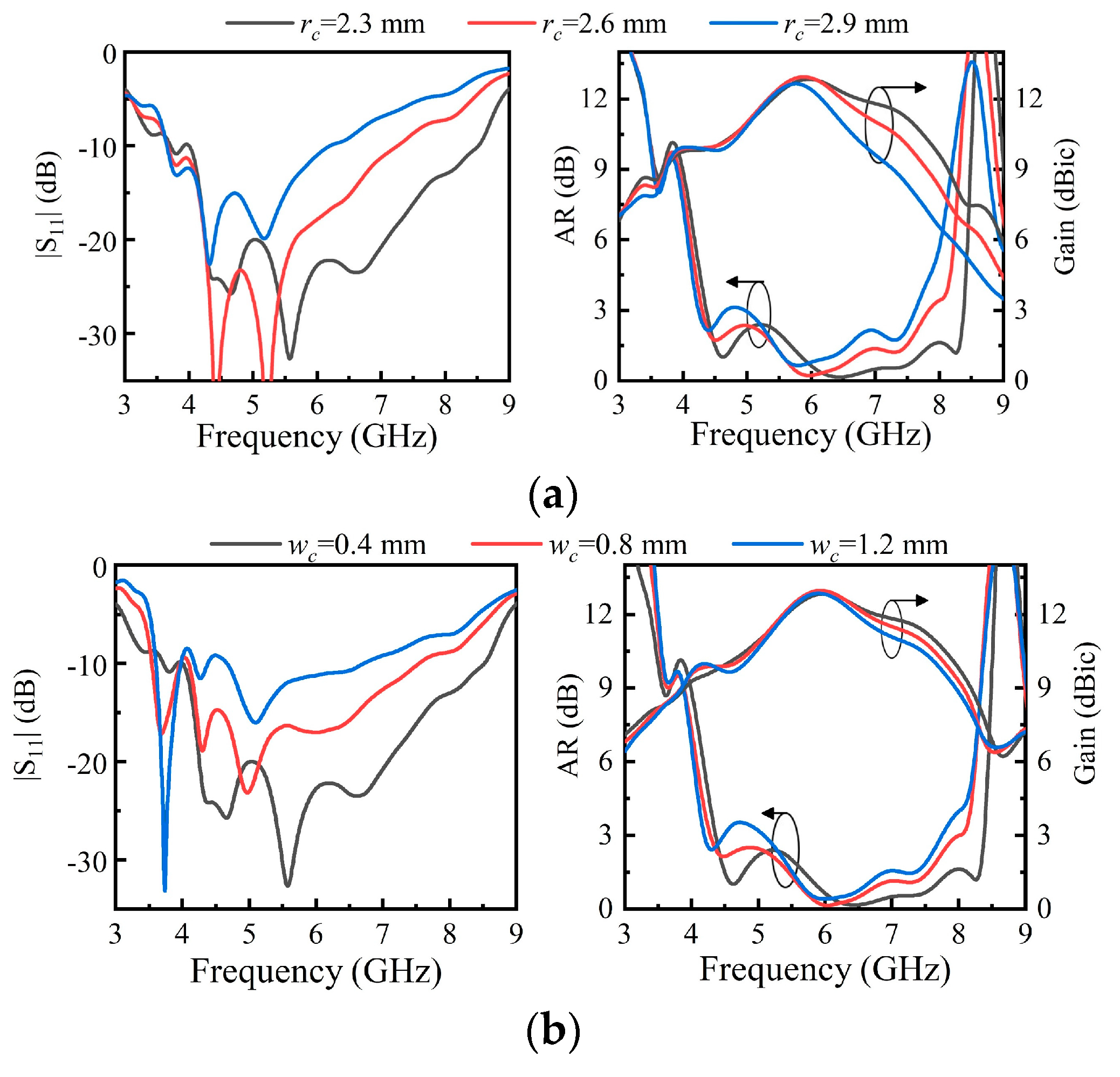
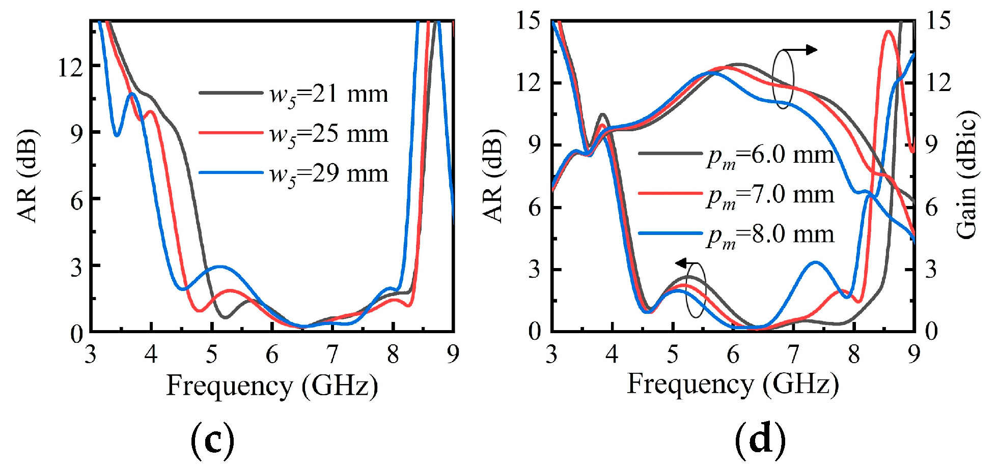
To understand the effects of several key parameters on the antenna performance, parametric studies were carried out. Figure 6a depicts the reflection coefficient, AR, and boresight gain with different radii rc of the phase delay line. The lower edge of the operating band remains stable while the upper edge drops rapidly with the increase in rc. At the same time, the minimum AR point shifts to a lower frequency, and the AR bandwidth become narrower. These changes indicate that the phase delay line provides the 90° phase difference required for CP radiation, while also realizing the impedance transformation near the full-wavelength region and promoting the impedance matching. In Figure 6b, the input impedance of the antenna is significantly affected by the variation of wc, whereas the AR and gain are slightly changed because rc remains unchanged. Figure 6c plots AR as a function of w5. It shows that w5 has an obvious influence on the first minimum AR point. With the increase in w5, the AR bandwidth is enlarged but the AR values become larger. This indicates that the AR bandwidth can be extended towards lower frequencies by appropriately widening the ends of the arms. Another parameter of interest is the side length of the AMC unit pm, as shown in Figure 6d. The parameter pm has a significant influence on AR and gain. With the increase in pm, AR values in lower frequencies decrease while the AR values in higher frequencies increase, leading to a narrower AR bandwidth. At the same time, the peak gain point shifts towards a lower frequency. This is because the central frequency of the AMC reflector shifts towards a lower frequency with the increase in pm.
To illustrate the mechanism of the antenna, the variation of the surface current distribution on the dipoles with time is exhibited in Figure 7. The dominant surface current at t = 0 is orthogonal to the dominant surface current at t = T/4. As the phase changes, the dominant surface currents rotate in an anticlockwise direction. Hence, the proposed antenna can generate right-hand circular polarization radiation. It can be seen from Figure 7a that considerable currents are distributed along the dipole ends, and the current direction is found to be orthogonal to the dominant current direction. The appearance of orthogonal currents improves the AR performance at lower frequencies, leading to the expansion of the AR bandwidth. Hence, the width of the dipole end w5 has an obvious influence on the first minimum AR point.

3. Simulation and Measurement Results

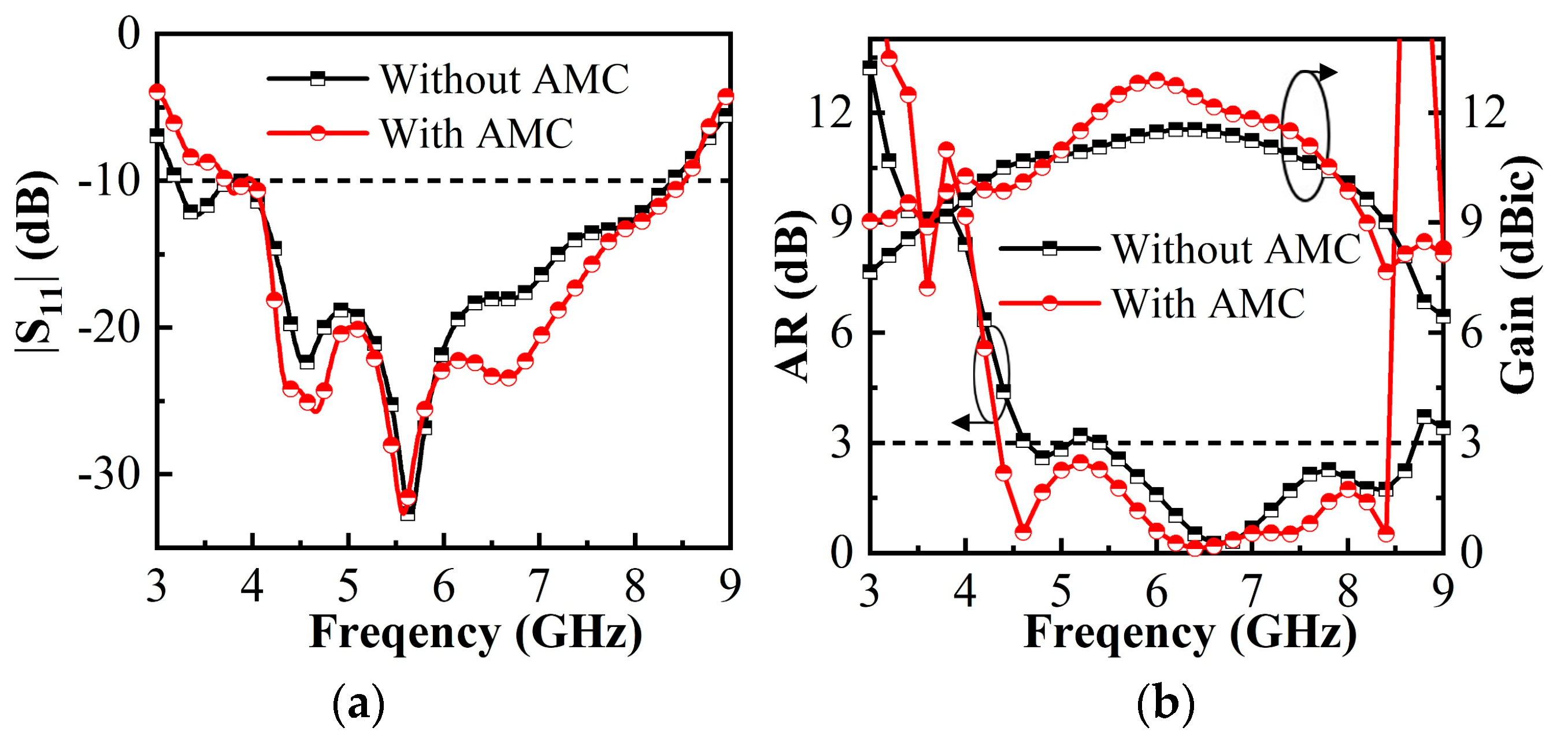
The proposed antenna and the reference antenna without the AMC reflector were analyzed simultaneously. As can be clearly observed from Figure 8, the impedance matching performance within the overlapping band is further improved after loading the AMC reflector, with a slight loss of |S11| bandwidth outside the working band. The enhancement of the impedance matching performance is due to the additional electromagnetic coupling between the dominant radiator and the AMC. The simulated AR and gain with/without the AMC are compared in Figure 8. The AR bandwidth of the antenna without the AMC is 46.8% (5.4–8.7 GHz), whereas the AR bandwidth with AMC loading is improved to 62.5% (4.4–8.4 GHz). In addition to widening in the AR bandwidth, the AR values are also reduced across the whole working band after loading the AMC. At the same time, the AR band slightly shifts towards a lower frequency along with the minimum AR point. The frequency shift may be due to the fact that the air gap is reduced and part of the air gap is replaced by the AMC substrate with a dielectric constant of 2.2 and thickness of 3.175 mm, as Figure 5a shows. The boresight gain of the proposed antenna is also significantly affected by the introduction of the AMC reflector. The gain is significantly improved near the center frequency at around 6 GHz, and the peak gain increases from 11.4 dBic to 12.9 dBic.
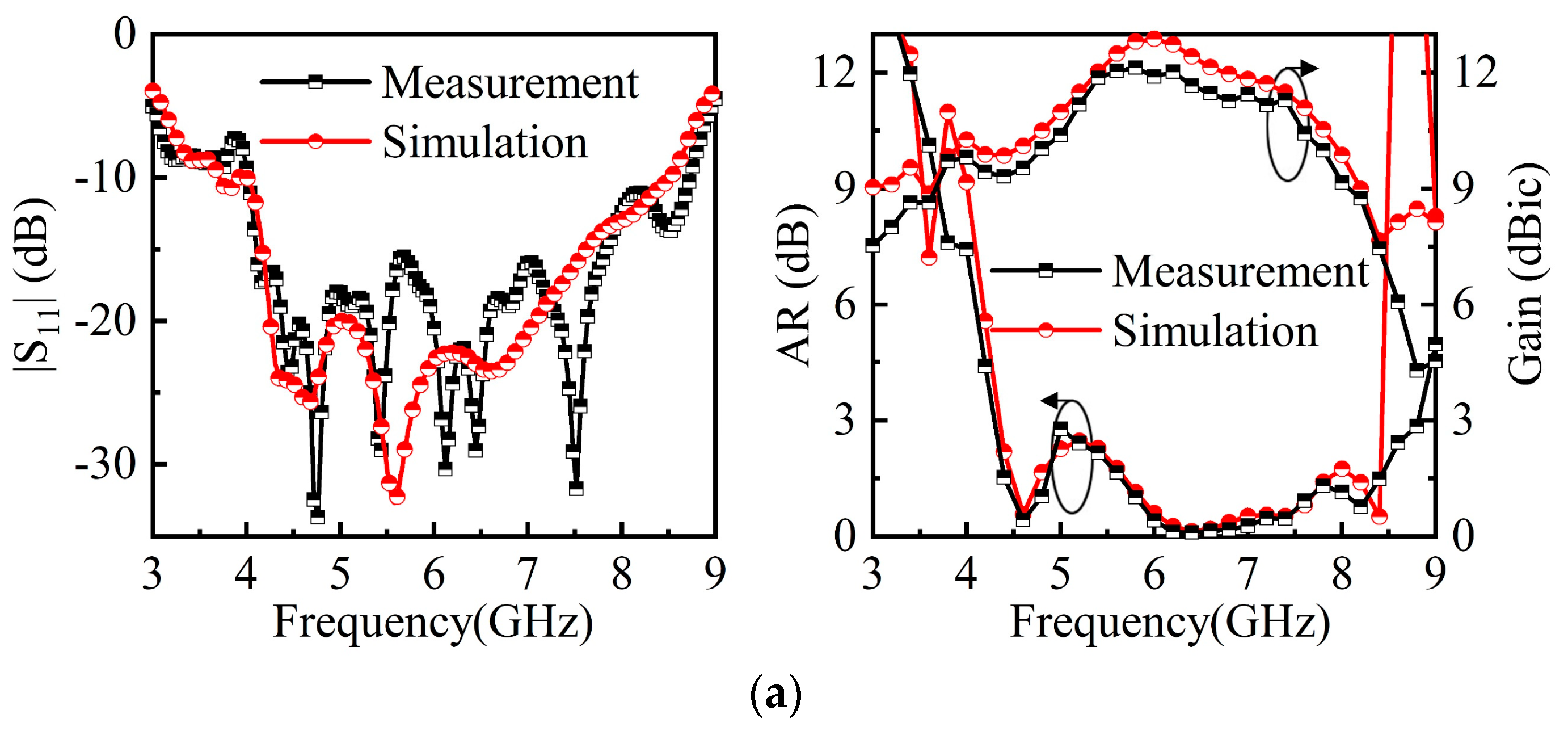
A prototype was fabricated and measured to verify the performance of the proposed antenna. The reflection coefficient of the antenna was measured using an E5071C network analyzer, and the AR, gain, and radiation patterns were measured using a Satimo System in an anechoic chamber. Figure 9 shows the simulation and measurement results of the reflection coefficient. The simulated and measured -10 dB |S11| bandwidths are 72% (4.0–8.5 GHz) and 74% (4.0–8.7 GHz), respectively. The measurement result is in good agreement with the simulation result, although there are slight deviations. The simulated 3 dB AR bandwidth is 62.5% from 4.4 GHz to 8.4 GHz, and the measured AR bandwidth is 67.7% from 4.3 GHz to 8.7 GHz. In addition to the good consistency of the bandwidth, the measured and simulated results also have similar trends and approximate minimum AR points. Both the simulated and measured gains are greater than 7 dBic within the operating band. The peak gain is 12.9 dBic for the simulation and 12.1 dBic for the measurement, and the average gains are 11.22 dBic and 10.69 dBic, respectively. The measured gain and simulated gain also have similar trends, but there is an inevitable gain loss due to the fabrication error and deviation in the measurement system.
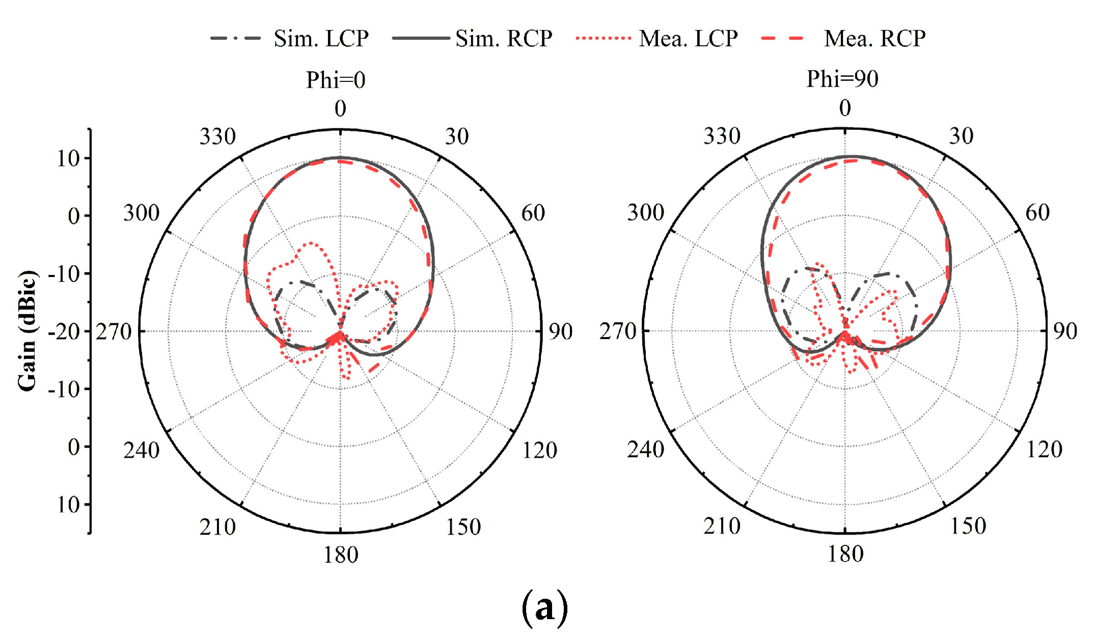
Figure 10 shows the simulated and measured radiation patterns of the proposed antenna in the xoz-plane and yoz-plane at 4.6, 6.0, and 8 GHz. It is obvious that unidirectional RHCP radiation is obtained in a broadband. The simulated cross-polarization (LHCP) level in the main lobe direction is less than −15 dB compared with the main polarization (RHCP). The measured and simulated radiation patterns are in good agreement. A narrower beamwidth is obtained as the frequency changes from 4.6 to 6 GHz. Consequently, the simulated boresight gain of the proposed antenna increases from 10 to 12.9 dBic. As the frequency increases to 8 GHz, the boresight gain gradually degrades with the increase in sidelobes. With the steady increase in the frequency, the dipole length is larger than one wavelength and the reverse current inevitably begins to appear on the dipole arms. The presence of the reverse current results in high sidelobe levels. Hence, the boresight gain is observed to decrease when the frequency exceeds the full-wavelength region. A comparison between this work and other related works is shown in Table 1. According to this table, it can be concluded that:
i.
Compared with other AMC-based antennas with single elements ([12,13,14,15,16,18,19]), the proposed antenna has wider impedance matching bandwidths and higher average gain.
ii.
Compared with other AMC-based CP antennas ([12,14,18,19]), the AR bandwidth of the proposed antenna is significantly wider. Hence, the overlapping bandwidth has been increased by at least 20%, and the average gain is significantly higher.
iii.
The proposed antenna has a similar average gain to that of the 1 × 4 antenna array in [12,25], which shows that the proposed antenna yields comparable gain without employing antenna arrays and complex feeding networks.

4. Conclusions

An AMC based broadband CP antenna with enhanced gain and low profile was proposed. A crossed dipole with full-wavelength was proposed to achieve a wider operating bandwidth and a higher gain. An AMC structure was further introduced as the reflector and the antenna profile was reduced. Numerical simulations and experiments were in good agreement. Results showed the proposed antenna exhibits an impedance matching bandwidth of 74% and an AR bandwidth of 67.7% centered at 6.4 GHz. The measured peak gain and average gain are 12.1 and 10.69 dBic within the operating band. The proposed design achieves higher gain without the introduction of antenna arrays and complex feeding networks, which is meaningful for practical application.

Author Contributions

Conceptualization, L.Q. and G.X.; methodology, L.Q. and G.X.; validation, L.Q.; investigation, L.Q.; resources, G.X.; writing—original draft preparation, L.Q.; writing—review and editing, L.Q. and G.X.; supervision, G.X.; project administration, G.X.; funding acquisition, G.X. All authors have read and agreed to the published version of the manuscript.

Funding

This research was funded by National Key R&D Program of China, grant number 2019YFB2204703.

Conflicts of Interest

The authors declare no conflict of interest.

References

  1. Nasimuddin, N.; Qing, X.; Chen, Z.N. Bandwidth enhancement of a single-feed circularly polarized antenna using a metasurface. IEEE Antennas Propag. Mag. 2016, 58, 39–46. [Google Scholar] [CrossRef]
  2. Esselle, K.P.; Verma, A.K. Wideband circularly polarized stacked microstrip antennas. IEEE Antennas Wirel. Propag. Lett. 2007, 6, 21–24. [Google Scholar]
  3. Liu, Q.; Chen, Z.N.; Liu, Y.; Li, C. Compact ultrawideband circularly polarized weakly coupled patch array antenna. IEEE Trans. Antennas Propag. 2017, 65, 2129–2134. [Google Scholar]
  4. Oraizi, H.; Pazoki, R. Wideband circularly polarized aperture-fed rotated stacked patch antenna. IEEE Trans. Antennas Propag. 2013, 61, 1048–1054. [Google Scholar] [CrossRef]
  5. Baik, J.W.; Lee, T.H.; Pyo, S.; Han, S.M.; Jeong, J.; Kim, Y.S. Broadband circularly polarized crossed dipole with parasitic loop resonators and its arrays. IEEE Trans. Antennas Wirel. Propag. 2011, 59, 80–87. [Google Scholar] [CrossRef]
  6. Feng, G.; Chen, L.; Xue, X.; Shi, X. Broadband circularly polarized crossed-dipole antenna with a single asymmetrical cross-loop. IEEE Antennas Wirel. Propag. Lett. 2017, 16, 3184–3187. [Google Scholar] [CrossRef]
  7. Tran, H.H.; Park, I.; Nguyen, T.K. Circularly polarized bandwidth-enhanced crossed dipole antenna with a simple single parasitic element. IEEE Antennas Wirel. Propag. Lett. 2017, 16, 1776–1779. [Google Scholar] [CrossRef]
  8. He, Y.; He, W.; Wong, H. A wideband circularly polarized cross-dipole antenna. IEEE Antennas Wirel. Propag. Lett. 2014, 13, 67–70. [Google Scholar]
  9. Tran, H.H.; Park, I. Wideband circularly polarized cavity-backed asymmetric crossed bowtie dipole antenna. IEEE Antennas Wirel. Propag. Lett. 2016, 15, 358–361. [Google Scholar] [CrossRef]
  10. Ta, S.X.; Park, I. Crossed dipole loaded with magneto-electric dipole for wideband and wide-beam circularly polarized radiation. IEEE Antennas Wirel. Propag. Lett. 2015, 14, 358–361. [Google Scholar] [CrossRef]
  11. Zhu, H.; Cheung, S.; Chung, K.L.; Yuk, T.I. Linear-to-circular polarization conversion using metasurface. IEEE Trans. Antennas Propag. 2013, 61, 4615–4623. [Google Scholar] [CrossRef] [Green Version]
  12. Lin, W.; Chen, S.; Ziolkowski, R.W.; Guo, Y.J. Reconfigurable wideband low-profile circularly polarized antenna and array enabled by an artificial magnetic conductor ground. IEEE Trans. Antennas Propag. 2018, 66, 1564–1569. [Google Scholar] [CrossRef]
  13. Xin, L.; Jiao, Y.C.; Li, Z. Wideband low-profile CPW-fed slot-loop antenna using an artificial magnetic conductor. Electron. Lett. 2018, 54, 673–674. [Google Scholar]
  14. Li, R.; Qin, Y.; Li, F.; Wu, L.; Cui, Y. AMC surface based on spiral strips and its applications for low-profile broadband planar antennas. IET Microw. Antennas Propag. 2019, 13, 326–333. [Google Scholar] [CrossRef]
  15. Li, M.; Li, Q.L.; Wang, B.; Zhou, C.F.; Cheung, S.W. A Low-Profile Dual-Polarized Dipole Antenna Using Wideband AMC Reflector. IEEE Trans. Antennas Propag. 2018, 66, 2610–2615. [Google Scholar] [CrossRef]
  16. Liu, Q.; Liu, H.; He, W.; He, S. A Low-Profile Dual-Band Dual-Polarized Antenna with an AMC Reflector for 5G Communications. IEEE Access 2020, 8, 24072–24080. [Google Scholar] [CrossRef]
  17. Ta, S.X.; Park, I.; Ziolkowski, R.W. Circularly polarized crossed dipole on an HIS for 2.4/5.2/5.8-GHz WLAN applications. IEEE Antennas Wirel. Propag. Lett. 2013, 12, 1464–1467. [Google Scholar] [CrossRef]
  18. Tran, H.H.; Park, I. A dual-wideband circularly polarized antenna using an artificial magnetic conductor. IEEE Antennas Wirel. Propag. Lett. 2016, 15, 950–953. [Google Scholar] [CrossRef]
  19. Feng, D.; Zhai, H.; Xi, L.; Yang, S.; Zhang, K.; Yang, D. A Broadband Low-profile Circular Polarized Antenna on an AMC Reflector. IEEE Antennas Wirel. Propag. Lett. 2017, 16, 2840–2843. [Google Scholar] [CrossRef]
  20. Tran, H.H.; Nguyen-Trong, N.; Le, T.T.; Abbosh, A.M.; Park, H.C. Low-profile wideband high-gain reconfigurable antenna with quad-polarization diversity. IEEE Trans. Antennas Propag. 2018, 66, 3741–3746. [Google Scholar] [CrossRef]
  21. Yang, W.; Che, W.; Jin, H.; Feng, W.; Xue, Q. A polarization-reconfigurable dipole antenna using polarization rotation AMC structure. IEEE Trans. Antenna Propag. 2015, 63, 5305–5315. [Google Scholar] [CrossRef]
  22. Ding, C.; Jones, B.; Guo, Y.J.; Qin, P.Y. Wideband matching of full-wavelength dipole with reflector for base station. IEEE Trans. Antennas Propag. 2017, 65, 5571–5576. [Google Scholar] [CrossRef]
  23. Ding, C.; Sun, H.; Zhu, H.; Jay Guo, Y. Achieving wider bandwidth with full-wavelength dipoles for 5G base stations. IEEE Trans. Antennas Propag. 2020, 68, 1119–1127. [Google Scholar] [CrossRef]
  24. Sun, G.H.; Wong, S.W.; Wong, H. A broadband antenna array using full-wave dipole. IEEE Access 2017, 5, 13054–13061. [Google Scholar] [CrossRef]
  25. Zhai, H.; Xi, L.; Zang, Y.; Li, L. A Low-Profile Dual-Polarized High-Isolation MIMO Antenna Arrays for Wideband Base-Station Applications. IEEE Trans. Antennas Propag. 2018, 66, 191–202. [Google Scholar] [CrossRef]
  26. Liu, J.; Li, J.; Yang, J.; Qi, Y.; Xu, R. AMC-Loaded Low-Profile Circularly Polarized Reconfigurable Antenna Array. IEEE Antennas Wirel. Propag. Lett. 2020, 19, 1276–1280. [Google Scholar] [CrossRef]
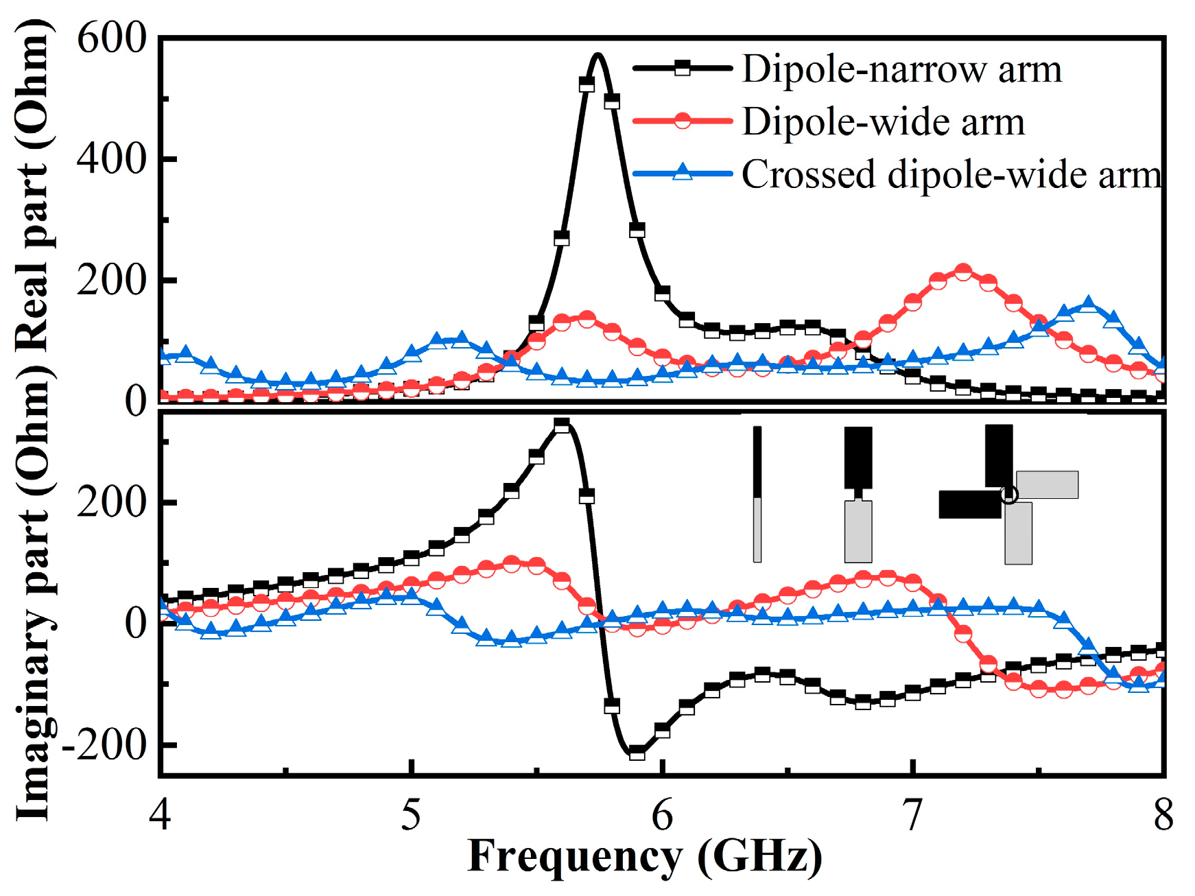
Figure 1. Simulated input impedances of three different dipoles. The thumbnail shows the structure of a dipole with a narrow arm, a dipole with a wide arm, and the crossed dipole, in order.
Electronics 10 02121 g001
Figure 2. Configuration evolution of the dipole and the side view of each antenna.
Electronics 10 02121 g002
Figure 3. Simulated reflection coefficient (a) and AR (b) of the reference antenna with different configurations.
Electronics 10 02121 g003
Figure 4. (a) The configuration and boundary conditions of the AMC element. (b) Simulation reflection phase for the AMC structure.
Electronics 10 02121 g004
Figure 5. (a) The side view of the reference antenna and the proposed antenna. (b) Configuration of the proposed antenna and details of the dominant radiator.
Electronics 10 02121 g005
Figure 6. Parametric studies on (a) the radius of phase delay line rc, (b) the width of phase delay line wc, (c) the width of ends w5, (d) the side length of the AMC unit pm.
Electronics 10 02121 g006aElectronics 10 02121 g006b
Figure 7. Current distributions on the crossed dipoles (a) 5.0 GHz, (b) 7.0 GHz.
Electronics 10 02121 g007
Figure 8. Simulated results of the crossed-dipole with/without AMC. (a) |S11|. (b) AR and gain.
Electronics 10 02121 g008
Figure 9. (a) Simulated and measured |S11|, AR, and boresight gain of the proposed antenna and (b) the fabricated prototype and measurement environments.
Electronics 10 02121 g009aElectronics 10 02121 g009b
Figure 10. Simulated and measured radiation patterns of the proposed CP antenna. (a) 4.6 GHz. (b) 6.0 GHz. (c) 8.0 GHz.
Electronics 10 02121 g010aElectronics 10 02121 g010b
Table 1. Comparison between the proposed antenna and previous works.
Ref.Antenna TypeNo. of ElementsIBW
(%)
Polarization
/ARBW (%)
Average Gain (dBi/dBic) Size   ( * λ 0 3 )
[12]Crossed-dipole with AMC146.2CP/26.35.90.94 × 0.94 × 0.05
1×427.7CP/21.711.32.83 × 0.94 × 0.05
[13]Slot loop antenna with AMC137.9LP5.50.67 × 0.45 × 0.05
[14]Dipole antenna with AMC142.0LP8.01.0 × 1.0 × 0.08
33.0CP/48.08.0
[15]Dipole antenna with AMC156.3LP8.11.48 × 1.2 × 0.14
60.1LP7.4
[16]Crossed dual-band bowtie dipoles with AMC119.8LP7.00.93 × 0.93 × 0.13
13.2LP8.1
[18]Crossed-dipole with AMC149.5CP/33.87.40.64 × 0.64 × 0.16
[19]Crossed-dipole with AMC166.3CP/44.75.21.5 × 1.5 × 0.12
[25]Crossed-dipole with AMC1×422.3LP10.21.01 × 3.28 × 0.11
[26]Monopole with AMC2×436.5CP/21.4715.13.20 × 0.82 × 0.12
This workFull-wavelength crossed-dipole with AMC174.0CP/67.710.71.6 × 1.6 × 0.14
Publisher’s Note: MDPI stays neutral with regard to jurisdictional claims in published maps and institutional affiliations.