Article

Design and Performance Analysis of a Compact Quad-Element UWB MIMO Antenna for Automotive Communications

by
Sriram Arumugam
,
Sangeetha Manoharan
,
Sandeep Kumar Palaniswamy
* and
Sachin Kumar
*
Department of Electronics and Communication Engineering, SRM Institute of Science and Technology, Kattankulathur, Chennai 603203, India
*
Authors to whom correspondence should be addressed.
Electronics 2021, 10(18), 2184; https://doi.org/10.3390/electronics10182184
Submission received: 1 August 2021 / Revised: 30 August 2021 / Accepted: 5 September 2021 / Published: 7 September 2021
(This article belongs to the Special Issue Emerging Research in Microwave Systems and Applications)

Abstract

:
This paper presents the design and analysis of a planar ultra-wideband (UWB) multiple-input-multiple-output (MIMO) antenna for modern vehicular communication systems. The proposed unit cell antenna structure was designed using modified elliptical radiators on a Rogers RO3003 substrate, has a size of 22 × 22 × 0.76 mm3, and covers an impedance bandwidth (S11 ≤ −10 dB) of 3.14 GHz to 12.24 GHz. The peak gain and efficiency of the unit cell prototype are 5.1 dBi and 81%, respectively. The unit cell was further developed into a MIMO antenna configuration with four elements placed orthogonal to each other in a single plane measuring 50 × 50 × 0.76 mm3. The measured isolation between the antenna elements was greater than 20 dB. The measured envelope correlation coefficient (ECC) of the MIMO antenna was less than 0.004, the diversity gain (DG) was greater than 9.67 dB, the total active reflection coefficient (TARC) was <−10 dB, and the mean effective gain (MEG) ratio was > 0.99. The characteristics of the proposed unit cell and the MIMO antenna were investigated for housing effects in order to validate the consistent performance of the antenna in the presence of conducting bodies. In addition, the radiation characteristics of the antenna when mounted on a vehicle were analyzed using a virtual model of the car. The results show that the proposed quad-element UWB MIMO array is compact, has good performance, and is well-suited for automotive applications.

1. Introduction

In light of recent advancements in the automobile communication industries, it seems that ultra-wideband (UWB) and multiple-input-multiple-output (MIMO) technologies are beneficial for vehicular communication with high data rates. Wireless communication applications, such as the global system for mobile communication (GSM), WLAN IEEE 802.11a/b/g/n, Wi-MAX, and dedicated short range communications (DSRC), are integrated into modern vehicles where the antenna size and position are important. The vehicular communication antennas must be compact, omnidirectional, and have minimal ground plane effects. The automobile industry has shown increased interest in various electronic integration issues [1], such as above-ground antennas, reduced cable lengths, passenger safety, and remote keyless entry based on vehicular-to-everything communication, in order to improve road safety, traffic-less movement, reliability, and efficiency. The unlicensed frequency bands of 2.4 GHz and 5.470–5.725 GHz benefit intelligent transportation systems (ITS), while a frequency band of 3.168–4.752 GHz offers multipath immunity for fast-moving vehicles in densely populated areas [2]. MIMO/diversity technology with a high data rate can be used for modern automotive communication to improve the link reliability of the communication system [3].
In the past, techniques such as complementary split-ring resonator (CSRR), and defected ground structure (DGS), were used for vehicular multiband operation [4,5]. The authors of [6] reported a low-profile UWB antenna with a power divider network, but the structure was too complex for integration into vehicular communication. MIMO technology is preferred for diversity applications, as it offers a high data rate and encounters multipath fading effects. However, high mutual coupling between the antenna elements can be a problem in MIMO systems. Many techniques, such as the orthogonal arrangement of the antenna elements [7], decoupling structures [8,9,10,11], quasi-self-complementary designs [12,13,14], and fractal structures [15], have been proposed for improving inter-element isolation. In [16], the radiating elements were wrapped around a cuboid polystyrene block to improve the correlation between them. In [17,18,19,20,21], different slots and stubs were used to improve the isolation between the antenna elements. In [22,23,24,25,26,27,28,29,30,31,32], different MIMO antenna designs were reported with the UWB frequency range. In addition, it is important to investigate the characteristics of the antennas installed on a large metal body for the vehicular environment [33,34,35,36]. In [37], a spiral antenna with a taper feed was presented, where the housing effect was investigated using the unit element for vehicular communication. In [38,39,40], car model analyses using far-field characteristics were presented to investigate the effect of the vehicular body on the radiation patterns of the antenna when it is placed in different locations.
In this study, a low-profile, compact-sized monopole antenna element was developed, working within an impedance bandwidth range of 3.14–12.24 GHz. Moreover, a four-port UWB MIMO antenna was developed with orthogonally placed resonating elements to achieve polarization diversity. In the ground plane of the antenna element, an inverted L-shaped stub was used, which provides three distinct characteristics: (a) better impedance matching, (b) a wider bandwidth, and (c) high inter-element isolation. The housing effect of the proposed four-port MIMO antenna was investigated. The housing effect has not been considered in the literature [10,11,12,13,14,15,16,17,18,19,20,21,22,23,24,25,26,27,28,29,30,31,32]; it was studied only for single element/two element MIMO antennas in [33,34,35,36,37]. Two different antenna placement scenarios were considered for studying housing effects. In the first scenario, the four-port MIMO antenna was positioned in the x-z plane, 50 mm above the metal plate, whereas in the second scenario, the MIMO antenna was positioned in the y-z plane, 65 mm above the metal plate. The on-car body analysis was performed in two different locations, namely, the rooftop and the side mirrors. It is understood that the side mirror is the best location for mounting the proposed antenna. Upon comparing the proposed UWB MIMO antenna to the designs available in the literature, we realized that the proposed antenna achieves a low envelope correlation coefficient (ECC) value of less than 0.004, and a high mean effective gain (MEG) value of 0.99.

2. Antenna Design

2.1. Unit Cell Design

The schematic of the proposed unit cell antenna is shown in Figure 1. The antenna was designed on a Rogers RO3003 substrate with a relative permittivity (εr) of 3, a height of 0.76 mm, and a loss tangent (tan δ) of 0.001. The radiating element was a combination of elliptical structures on the front of the dielectric substrate, and a modified ground plane on the back. A 50 Ω microstrip line was used to feed the antenna. The dimensions of the antenna are: L = 22 mm, W = 22 mm, g = 6.3 mm, Sw1 = 0.7 mm, Sw2 = 0.5 mm, r1 = 6.2 mm, r2 = 1.7 mm, r3 = 4 mm, r4 = 2.7 mm, θ1 = θ2 = 45°, w1 = 2.16 mm, w2 = 1.66 mm, l1 = 1.2 mm, l2 = 8.05 mm, S = 2.3 mm, and d = 2.2 mm.
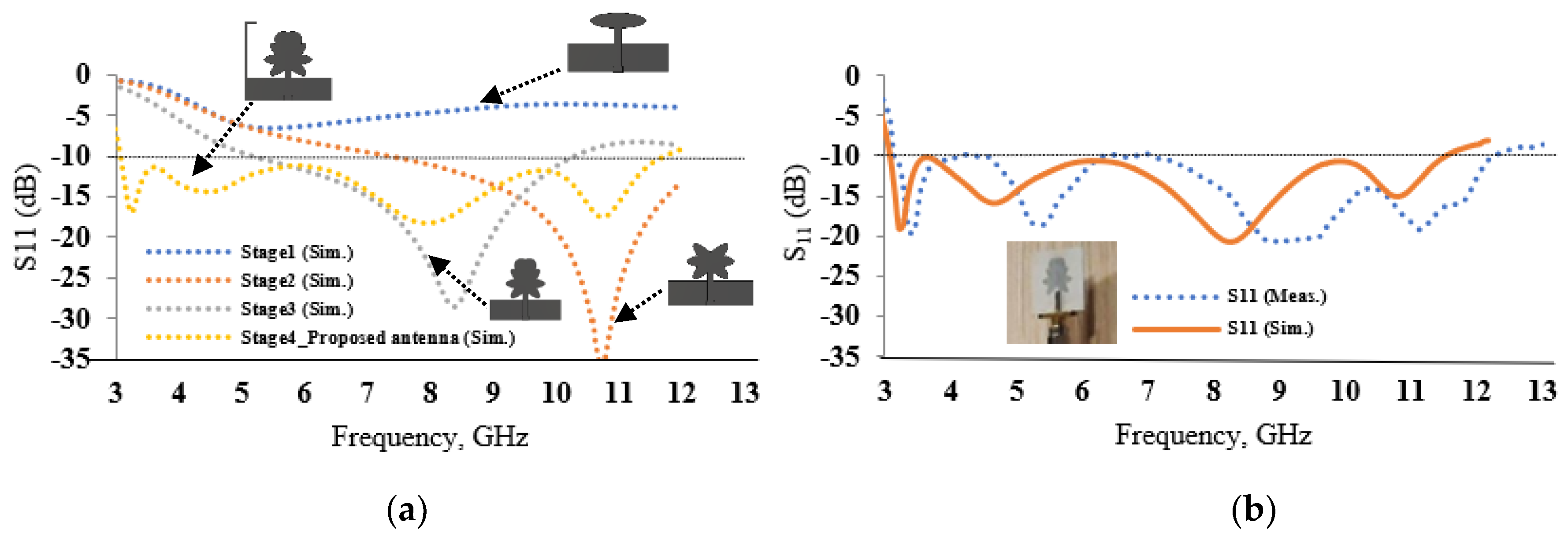
The evolution of the proposed UWB antenna is shown in Figure 2, and its surface current distribution in Figure 3. As shown in the first stage (Figure 2a), the antenna consisted of a low-profile, compact-sized microstrip line-fed elliptical patch. However, the antenna had poor impedance matching, as shown in Figure 4a. The two elliptical radiators, rotated at an angle of 45° in the center, as shown in Figure 2b, were integrated into the microstrip line-fed elliptical patch to increase the impedance bandwidth. This increased the current path length to ~16.16λmin, thus providing a wide impedance bandwidth.
The surface current distribution of the proposed UWB antenna at various stages is shown in Figure 3. The integration of elliptical elements produces inductive loading, which increases the Q factor, as illustrated in Equation (1).
Q = 2 f L   R = X L R
However, the lower UWB frequency range is not covered. Therefore, the electrical length of the radiator was increased to ~20.87λmin by convolving two elliptical pairs on top (with radii of r3 and r4) in both sides at an angle of 45°, as shown in the third stage. This lowered the frequency, resulting in a bandwidth of 5.1 to 10.3 GHz. Figure 3c depicts the surface current distribution at 8.2 GHz. Figure 3d shows that, by introducing an inverted L-shaped stub in the ground plane, good impedance matching was achieved throughout the UWB, resulting in a bandwidth ranging from 3 GHz to 11.7 GHz.
The fabricated prototype UWB antenna was measured using an Anritsu MS2037C vector network analyzer. The antenna has simulated and measured bandwidths of 8.7 GHz (3–11.7 GHz), and 9.1 GHz (3.14–12.24 GHz), respectively, as shown in Figure 4b. Figure 5 shows a measured peak gain of 5.1 dBi, and an efficiency of more than 81%.

2.2. MIMO Antenna Design

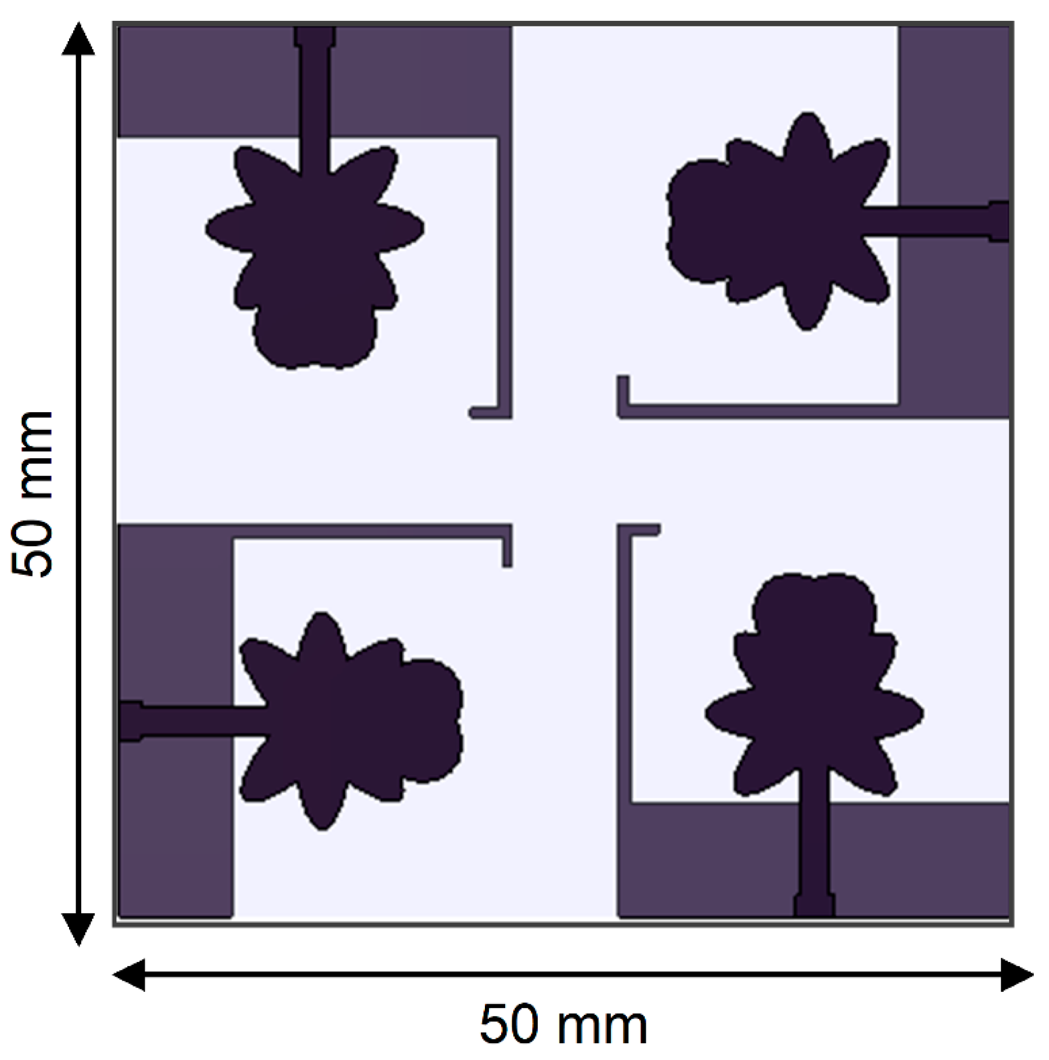
In the modern automotive industry, the UWB MIMO/diversity technique is used to improve link reliability, lower high data rates, and to overcome the effect of multipath fading. The diversity technique improves the strength of vehicle-to-infrastructure (V2I) communications. The MIMO/diversity array configuration is constructed by placing four unit cells orthogonal to each other, with an inter-element spacing of 6 mm, and dimensions of 50 mm × 50 mm to ensure good signal reception in a multipath environment, as shown in Figure 6. The radiation pattern characteristics of the prototype UWB MIMO antenna were measured in an anechoic chamber.
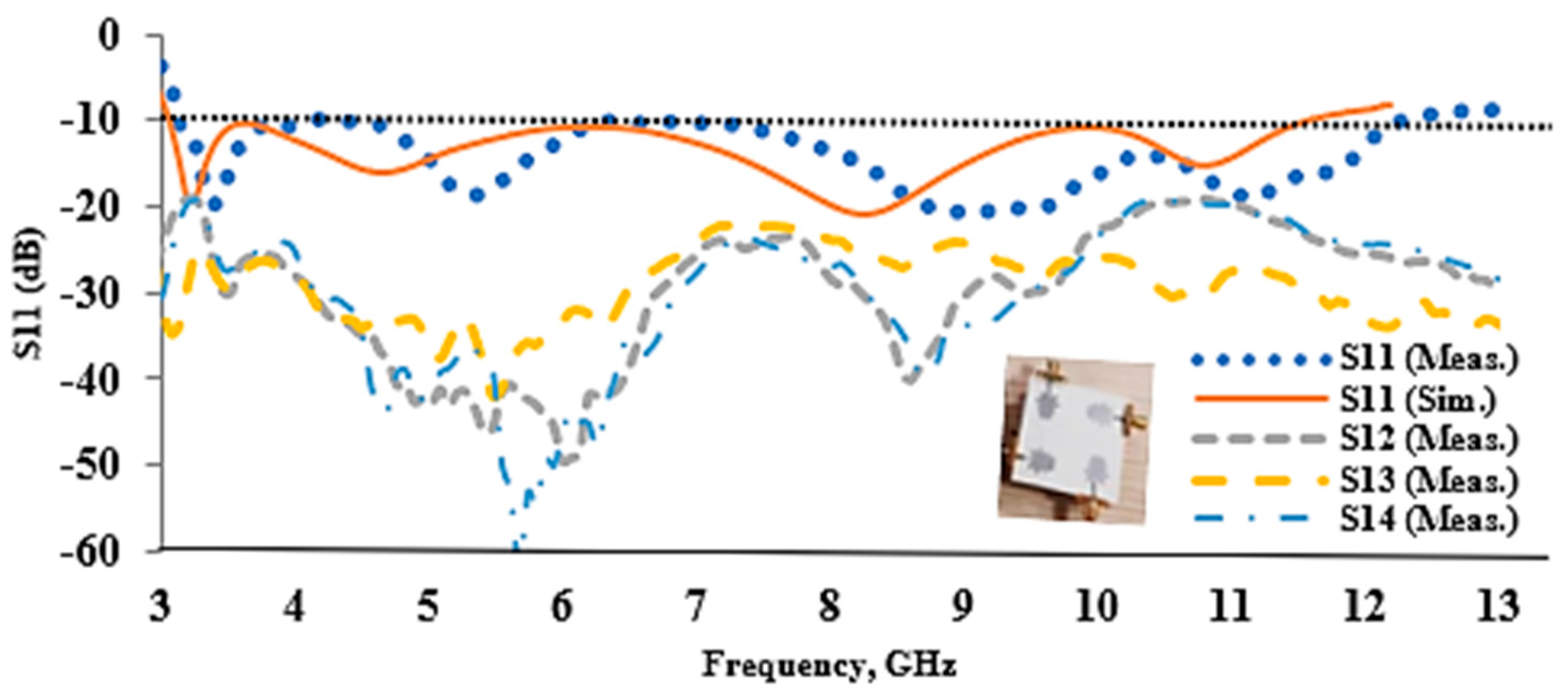
Figure 7 shows the S-parameter characteristics of the MIMO antenna. The impedance bandwidth of the antenna is 3.14–12.24 GHz, and the isolation is more than 20 dB between the ports over the operating bandwidth. The S-parameters at port-1 are only shown because of the symmetric structure of the four-element MIMO antenna. Figure 8 depicts the radiation patterns of the proposed quad-element MIMO antenna at four different frequencies (4, 6, 8, and 10 GHz) in the x-z (H-plane) and y-z (E-plane) planes. The proposed antenna exhibits an omnidirectional radiation pattern. The measured results offer good coverage for UWB communications.

2.3. MIMO Antenna Performance

The diversity performance of the proposed MIMO antenna was analyzed using important metrics, such as the ECC, the diversity gain (DG), the total active reflection coefficient (TARC), and the MEG ratio. Table 1 shows the proposed UWB MIMO antenna performance at four different frequencies (4, 6, 8, and 10 GHz).

2.3.1. Envelope Correlation Coefficient (ECC) and Diversity Gain (DG)

The ECC shows the correlation between the unit antenna elements. An ECC of <0.5 is an acceptable limit to be considered [14]. The ECC of the proposed antenna was evaluated using the far-field equation (2). The ECC in the UWB operating range is less than 0.004, as shown in Figure 9a. Another important parameter for determining the diversity effectiveness is the DG, which is calculated using Equation (3). Figure 9b shows that the DG over the UWB range is greater than 9.67 dB.
ρ e = |   [ F 1 ( θ , φ ) . F 2 ( θ , φ ] d | 2   | F 1 ( θ , φ ) | 2 d     | F 2 ( θ , φ ) | 2 d
D G = 10     1 ρ e 2

2.3.2. Mean Effective Gain (MEG) and Total Active Reflection Coefficient (TARC)

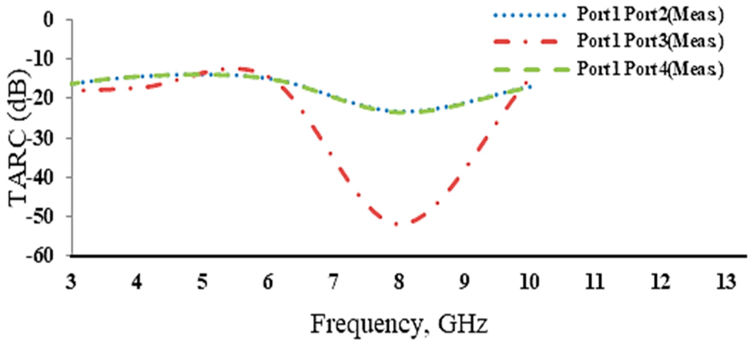
The MEG is the power produced by the diversity antenna to the power accepted by an omnidirectional antenna [8], and it can be calculated using Equation (4). Equation (5) can be used to calculate the MEG ratio to measure the antenna power imbalance. The TARC is a measure of diversity array efficiency that reflects the effects of mutual coupling and can be calculated using Equation (6). Table 1 shows that the measured MEG ratio and the TARC are greater than 0.99 and less than −14.41 dB, respectively. Figure 10 shows that the TARC is stable due to the high isolation between the unit elements.
M E G = 0.5   ( 1 j = 1 M | S i j | 2 )
K = m i n   ( M E G 1 / M E G 2 ,     M E G 2 / M E G 1 )
T A R C   = ( | ( S 11 + S 12 e j θ ) | 2 + | ( S 21 + S 22 e j θ ) | 2   ) 2
Table 2 compares the reported and proposed UWB MIMO antenna designs. The main advantages of the proposed antenna are:
  • Unlike the complex antenna structures reported in [7,23,26,27,30,32], the proposed antenna has a simple geometry comprised of a basic elliptical radiator monopole configuration.
  • When compared to [10,20,22,26,27,30], the spacing between the antenna elements is small and, thus, more elements can be packed into a small space.
  • The proposed antenna has less inter-element coupling and a lower ECC value than previous reported designs [12,14,15,18,20,26,27,30,32].
  • The proposed MIMO antenna performs better in terms of the DG, the TARC, and the MEG, whereas in [11,15,16,22,24,32] the DG of the reported antenna designs was not investigated.
  • The majority of papers reported in the literature did not show the MEG value, with the exception of [27], where the MEG value was less than the proposed MIMO antenna.

3. Antenna Housing Effects

In many situations, the radiation characteristics of the antenna changes because of nearby obstructions. Therefore, it is necessary to investigate the antenna’s effects on a large metal body. For in-car communications, the antenna can be integrated into the inside of the shark fin on a car’s roof, or embedded on PCB circuits, and mounted anywhere in the vehicle. The proposed antenna is integrated on the car’s roof (large ground plane), with a size of lm × wm × hm, taking into account that plastic is insignificant and unobserved during the housing effect.
Two different scenarios were considered for the antenna (unit antenna element and MIMO) placement, as shown in Figure 11. In the first scenario, the antenna is positioned vertically in the x-z plane at a distance of 10 mm (single element) or 50 mm (MIMO) above the metal plate. In the second scenario, the antenna is positioned horizontally in the y-z plane at a distance of 25 mm (single element) or 65 mm (MIMO) above the metal plate.
Figure 11 depicts the effects of housing on the bandwidth characteristics of the single element and MIMO antennas of different dimensions. The large metal plate has a negligible effect on the bandwidth of the proposed antenna element and the MIMO antenna in both the x-z and the y-z planes. The radiation pattern characteristics of the proposed antenna were analyzed for both single element and MIMO, where antennas placed directly on a metal plate may affect the omnidirectional radiation patterns in the x-z plane. Therefore, the aforementioned conditions must be fulfilled in order to avoid diffraction effects on the antenna’s radiation property [33]. Figure 12 depicts the radiation patterns of the single element and the MIMO antennas on different metal plates in the x-z and y-z planes. As the large metal plate acts as a reflector, the directivity of the antenna is increased by ~5 dB for a single element, and by ~2 dB for a MIMO antenna. The variation in diversity is caused by the greater height between the metal plate and the MIMO antenna in comparison to the unit antenna element.

4. On-Vehicle Characteristics of the Antenna

It was necessary to investigate the radiation performance of the proposed antenna when integrated at various vehicle locations. A CAD model of the car was chosen to simulate the proposed antenna in an ideal environment (free space) using CST Microwave Studio®. The surfaces of the car were modelled as PECs. The radiation characteristics of the antenna were investigated at two different locations on the vehicle. The rooftop and side mirrors were chosen for the antenna placement. Figure 13 depicts an acceptable variation of the proposed antenna radiation patterns on the car body at frequencies of 4, 6, 8, and 10 GHz (in the x-z plane, y-z plane, and x-y plane). Due to the large PEC surface of the vehicular body, which emits radiation in all directions, the antenna mounted on the rooftop exhibited an omnidirectional radiation pattern with deep nulls at 6, 8, and 10 GHz frequencies, while the antenna element implanted on the car side mirror showed an omnidirectional pattern with little distortion, and a maximum radiation ranging between 30° and 90°. Thus, it is clear that the side mirror is the best location for mounting the proposed antenna. It is understood that small back radiation appears in all positions because of the radiating field dispersion throughout the vehicle body.

5. Conclusions

The proposed UWB MIMO antenna is designed to handle multimedia communications and high-speed data in a vehicular environment. The proposed UWB MIMO antenna provides better performance with an ECC < 0.004, a DG > 9.90, a TARC < −14.41, a MEG of 0.99, isolation > 20 dB, and omnidirectional radiation in most frequency bands. The performance characteristics of a single antenna element and a MIMO antenna on different-sized metallic plates with ideal mounting positions were investigated. Further, on-car body analysis was investigated in two different positions, on the rooftop and the side mirror, where an insignificant deviation in radiation patterns was seen in all cases. Therefore, the proposed UWB MIMO antenna could be a good candidate for UWB automotive communications.

Author Contributions

Conceptualization, S.A., S.M., S.K.P. and S.K.; methodology, S.K.P.; software, S.A.; validation, S.M. and S.K.P.; formal analysis, S.A. and S.M.; investigation, S.A., S.M., S.K.P. and S.K.; resources, S.A., S.M., S.K.P. and S.K., data curation, S.A.; writing and original draft preparation, S.A., S.M., S.K.P. and S.K.; writing review and editing, S.M. and S.K.P.; supervision, S.M. and S.K.P.; project administration, S.A., S.M., S.K.P. and S.K. All authors have read and agreed to the published version of the manuscript.

Funding

This research received no external funding.

Acknowledgments

The authors are grateful to the “Fund for Improvement of S&T Infrastructure (FIST)” of the Department of Science & Technology (DST), SRM Institute of Science and Technology, Kattankulathur, for providing access and facilities for testing the antenna.

Conflicts of Interest

The authors declare no conflict of interest.

References

  1. Pell, B.D.; Sulic, E.; Rowe, W.S.T.; Ghorbani, K.; John, S. Advancements in Automotive Antennas; IntechOpen: London, UK, 2011. [Google Scholar] [CrossRef]
  2. Zuazola, I.J.G.; Elmirghani, J.M.H.; Batchelor, J.C. A Telematics System Using In-Vehicle UWB Communications; IntechOpen: London, UK, 2011. [Google Scholar] [CrossRef] [Green Version]
  3. Garcia Zuazola, I.; Elmirghani, J.; Batchelor, J. High-speed ultra-wide band in-car wireless channel measurements. Commun. IET 2009, 3, 1115–1123. [Google Scholar] [CrossRef] [Green Version]
  4. Abdalla, M.A.; Wahba, W.W.; Allam, A.A. Analysis and design of a compact CRLH inspired—Defected ground resonators for triple band antenna applications. Eng. Sci. Technol. Int. J. 2020, 23, 114–122. [Google Scholar] [CrossRef]
  5. Imran, A.I.; Elwi, T.A. A cylindrical wideband slotted patch antenna loaded with Frequency Selective Surface for MRI applications. Eng. Sci. Technol. Int. J. 2017, 20, 990–996. [Google Scholar] [CrossRef]
  6. Sharma, M.K.; Kumar, M.; Saini, J.P. Design and Analysis of a Compact UWB-MIMO Antenna with Improved Isolation for UWB/WLAN Applications. Wirel. Pers. Commun. 2021, 1–16. [Google Scholar] [CrossRef]
  7. Behdad, N.; Li, M.; Yusuf, Y. A Very Low-Profile, Omnidirectional, Ultrawideband Antenna. IEEE Antennas Wirel. Propag. Lett. 2013, 12, 280–283. [Google Scholar] [CrossRef]
  8. Mao, C.; Chu, Q. Compact Coradiator UWB-MIMO Antenna with Dual Polarization. IEEE Trans. Antennas Propag. 2014, 62, 4474–4480. [Google Scholar] [CrossRef]
  9. Tang, X.; Yao, Z.; Li, Y.; Zong, W.; Liu, G.; Shan, F. A high performance UWB MIMO antenna with defected ground structure and U-shape branches. Int. J. RF Microw. Comput.-Aided Eng. 2021, 31, e22270. [Google Scholar] [CrossRef]
  10. Ali, W.A.; Ibrahim, A.A. A Compact Double-Sided MIMO Antenna with an Improved Isolation for UWB Applications. AEU-Int. J. Electron. Commun. 2017, 82, 7–13. [Google Scholar] [CrossRef]
  11. Altaf, A.; Iqbal, A.; Smida, A.; Smida, J.; Althuwayb, A.A.; Hassan Kiani, S.; Alibakhshikenari, M.; Falcone, F.; Limiti, E. Isolation Improvement in UWB-MIMO Antenna System Using Slotted Stub. Electronics 2020, 9, 1582. [Google Scholar] [CrossRef]
  12. Liu, X.; Wang, Z.; Yin, Y.; Ren, J.; Wu, J. A Compact Ultrawideband MIMO Antenna Using QSCA for High Isolation. IEEE Antennas Wirel. Propag. Lett. 2014, 13, 1497–1500. [Google Scholar] [CrossRef]
  13. Srivastava, G.; Mohan, A. Compact MIMO Slot Antenna for UWB Applications. IEEE Antennas Wirel. Propag. Lett. 2016, 15, 1057–1060. [Google Scholar] [CrossRef]
  14. Sultan, K.S.; Abdullah, H.H. Planar UWB MIMO-Diversity Antenna with Dual Notch Characteristics. Prog. Electromagn. Res. C 2019, 93, 119–129. [Google Scholar] [CrossRef] [Green Version]
  15. Tripathi, S.; Mohan, A.; Yadav, S. A Compact Koch Fractal UWB MIMO Antenna with WLAN Band-Rejection. IEEE Antennas Wirel. Propag. Lett. 2015, 14, 1565–1568. [Google Scholar] [CrossRef]
  16. Bilal, M.; Saleem, R.; Abbasi Hammad, H.; Shafique, M.F.; Brown, A.K. An FSS-Based Nonplanar Quad-Element UWB-MIMO Antenna System. Antennas Wirel. Propag. Lett. 2017, 16, 987–990. [Google Scholar] [CrossRef]
  17. Kumar, J.P.; Karunakar, G. Compact C-shaped MIMO diversity antenna for quad band applications with hexagonal stub for isolation improvement. Int. J. RF Microw. Comput.-Aided Eng. 2019, 29, e21971. [Google Scholar] [CrossRef]
  18. Pannu, P.; Sharma, D.K. A low-profile quad-port UWB MIMO antenna using defected ground structure with dual notch-band behavior. Int. J. RF Microw. Comput.-Aided Eng. 2020, 30, e22288. [Google Scholar] [CrossRef]
  19. Srivastava, K.; Kumar, A.; Kanaujia, B.K.; Dwari, S.; Kumar, S. A CPW-fed UWB MIMO antenna with integrated GSM band and dual band notches. Int. J. RF Microw. Comput.-Aided Eng. 2019, 29, e21433. [Google Scholar] [CrossRef] [Green Version]
  20. Mathur, R.; Dwari, S. Compact CPW-Fed Ultrawideband MIMO Antenna Using Hexagonal Ring Monopole Antenna Elements. AEU-Int. J. Electron. Commun. 2018, 93, 1–6. [Google Scholar] [CrossRef]
  21. Sipal, D.; Abegaonkar, M.P.; Koul, S.K. Compact planar 2 × 2 and 4 × 4 UWB mimo antenna arrays for portable wireless devices. Microw. Opt. Technol. Lett. 2018, 60, 86–92. [Google Scholar] [CrossRef]
  22. Saad, A.A.R. Approach for Improving Inter-Element Isolation of Orthogonally Polarised MIMO Slot Antenna over Ultra-Wide Bandwidth. Electron. Lett. 2018, 54, 1062–1064. [Google Scholar] [CrossRef]
  23. Kumar, R.; Surushe, G. Design of microstrip-fed printed UWB diversity antenna with tee crossed shaped structure. Eng. Sci. Technol. Int. J. 2016, 19, 946–955. [Google Scholar] [CrossRef] [Green Version]
  24. Naktong, W.; Ruengwaree, A. Four-Port Rectangular Monopole Antenna for UWB-MIMO Applications. Prog. Electromagn. Res. B 2020, 87, 19–38. [Google Scholar] [CrossRef]
  25. Farahani, M.; Mohammad-Ali-Nezhad, S. A novel UWB printed monopole MIMO antenna with non-uniform transmission line using nonlinear model predictive. Eng. Sci. Technol. Int. J. 2020, 23, 1385–1396. [Google Scholar] [CrossRef]
  26. Hasan, M.N.; Chu, S.; Bashir, S. A DGS monopole antenna loaded with U-shape stub for UWB MIMO applications. Microw. Opt. Technol. Lett. 2019, 61, 2141–2149. [Google Scholar] [CrossRef]
  27. Tiwari, R.N.; Singh, P.; Kanaujia, B.K.; Srivastava, K. Neutralization Technique Based Two and Four Port High Isolation MIMO Antennas for UWB Communication. AEU-Int. J. Electron. Commun. 2019, 110, 152828. [Google Scholar] [CrossRef]
  28. Boologam, A.V.; Krishnan, K.; Palaniswamy, S.K.; Manimegalai, C.T.; Gauni, S. On the Design and Analysis of Compact Super-Wideband Quad Element Chiral MIMO Array for High Data Rate Applications. Electronics 2020, 9, 1995. [Google Scholar] [CrossRef]
  29. Singhal, S. Four element ultra-wideband fractal multiple-input multiple-output antenna. Microw. Opt. Technol. Lett. 2019, 61, 2811–2818. [Google Scholar] [CrossRef]
  30. Premalatha, J.; Sheela, D. Compact four-port vertically polarized UWB monopole antenna for MIMO communications. Circuit World 2020, in press. [Google Scholar] [CrossRef]
  31. Raheja, D.K.; Kanaujia, B.K.; Kumar, S. Compact four-port MIMO antenna on slotted-edge substrate with dual-band rejection characteristics. Int. J. RF Microw. Comput.-Aided Eng. 2019, 29, e21756. [Google Scholar] [CrossRef]
  32. Sipal, D.; Abegaonkar, M.P.; Koul, S.K. Easily Extendable Compact Planar UWB MIMO Antenna Array. IEEE Antennas Wirel. Propag. Lett. 2017, 16, 2328–2331. [Google Scholar] [CrossRef]
  33. Bahadori, K.; Rahmat-Samii, Y. A Miniaturized Elliptic-Card UWB Antenna with WLAN Band Rejection for Wireless Communications. IEEE Trans. Antennas Propag. 2007, 55, 3326–3332. [Google Scholar] [CrossRef]
  34. Chacko, B.P.; Augustin, G.; Denidni, T.A. Uniplanar polarisation diversity antenna for ultra-wideband systems. IET Microw. Antennas Propag. 2013, 7, 851–857. [Google Scholar] [CrossRef]
  35. Chacko, B.P.; Augustin, G.; Denidni, T.A. Uniplanar Slot Antenna for Ultrawideband Polarization-Diversity Applications. IEEE Antennas Wirel. Propag. Lett. 2013, 12, 88–91. [Google Scholar] [CrossRef]
  36. Alsath, M.G.N.; Kanagasabai, M. Compact UWB Monopole Antenna for Automotive Communications. IEEE Trans. Antennas Propag. 2015, 63, 4204–4208. [Google Scholar] [CrossRef]
  37. Ramya; Rao, T.R. Penta-band linear tapered feed planar spiral antenna for vehicular communications. Int. J. Microw. Wirel. Technol. 2017, 9, 1523–1532. [Google Scholar] [CrossRef]
  38. Bactavatchalame, P.; Rajakani, K. Compact broadband slot-based MIMO antenna array for vehicular environment. Microw. Opt. Technol. Lett. 2020, 62, 2024–2032. [Google Scholar] [CrossRef]
  39. Madhav, B.T.P.; Anilkumar, T. Design and study of multiband planar wheel-like fractal antenna for vehicular communication applications. Microw. Opt. Technol. Lett. 2018, 60, 1985–1993. [Google Scholar] [CrossRef]
  40. Ez-Zaki, F.; Belahrach, H.; Ghammaz, A. Broadband microstrip antennas with Cantor set fractal slots for vehicular communications. Int. J. Microw. Wirel. Technol. 2021, 13, 295–308. [Google Scholar] [CrossRef]
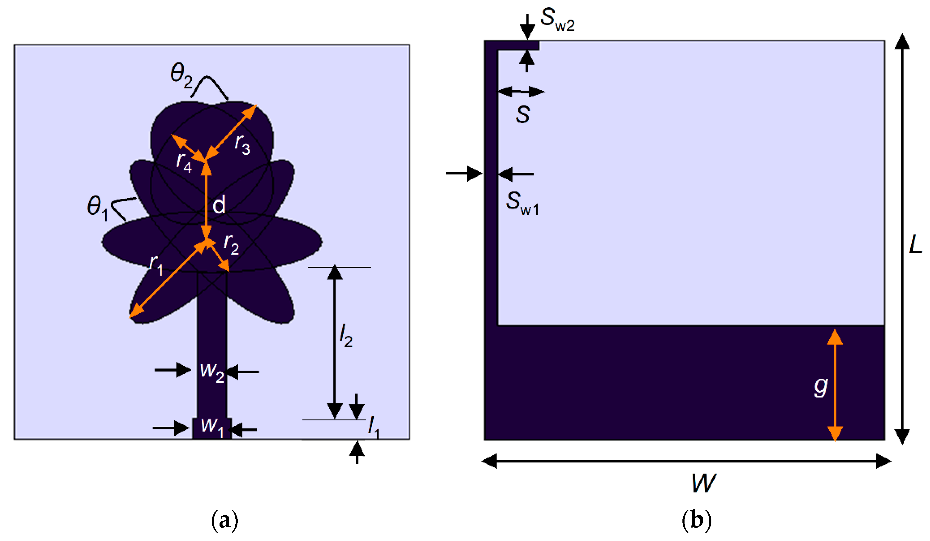
Figure 1. Proposed ultra-wideband (UWB) antenna (a) front view (b) back view.
Electronics 10 02184 g001
Figure 2. Evolution of the proposed antenna (a) first stage (b) second stage (c) third stage (d) fourth stage.
Electronics 10 02184 g002
Figure 3. Surface current distribution at different stages of the proposed UWB antenna: (a) 5.2 GHz (b) 10.7 GHz (c) 8.2 GHz, and (d) 8 GHz.
Electronics 10 02184 g003
Figure 4. (a) simulated S11 characteristics during evolution stages (b) simulated and measured S11 characteristics of the proposed antenna element.
Electronics 10 02184 g004
Figure 5. Gain and efficiency of the proposed UWB antenna.
Electronics 10 02184 g005
Figure 6. Quad-port UWB multiple-input-multiple-output (MIMO) antenna.
Electronics 10 02184 g006
Figure 7. S-parameters of the proposed UWB MIMO antenna.
Electronics 10 02184 g007
Figure 8. Measured radiation patterns of the UWB MIMO antenna in x-z plane and y-z plane.
Electronics 10 02184 g008
Figure 9. Performance of the proposed UWB MIMO antenna (a) Envelope Correlation Coefficient (ECC) (b) Diversity Gain (DG).
Electronics 10 02184 g009
Figure 10. Measured total active reflection coefficient (TARC) of the proposed MIMO antenna.
Electronics 10 02184 g010
Figure 11. The unit antenna element/MIMO antenna bandwidth performance when the housing effect is taken into account.
Electronics 10 02184 g011
Figure 12. The unit antenna element/MIMO antenna radiation patterns when the housing effect is taken into account (a) single antenna element in the y-z and x-z planes on different sized metal plates (b) MIMO antenna in the y-z and x-z planes on a metal plate of 800 mm × 800 mm × 50 mm.
Electronics 10 02184 g012
Figure 13. Far-field patterns in different positions on a car.
Electronics 10 02184 g013
Table 1. UWB MIMO antenna performance at different frequencies.
Frequency (GHz)ECC (Far-Field)Isolation (dB)DG
(dB)
TARC (dB)MEG Ratio
40.0001>28.609.990−14.410.990
60.0003>33.379.998−14.930.993
80.0002>23.499.998−51.900.998
100.0001>25.909.976−14.780.993
Table 2. Comparison of the proposed antenna and the antenna reported in the literature.
Ref.Antenna Size (mm)Number of Unit ElementsImpedance Bandwidth (GHz)Isolation (dB)ECCDG (dB)TARC (dB)MEG
[10]40 × 4047.9>20<0.004---------
[12]60 × 4148.8>20<0.25---------
[14]37 × 4649.5>20<0.0059.96------
[15]45 × 4548.6>17<0.005---------
[16]32 × 3647.5>20<0.002---------
[18]45 × 45414>22<0.0110<-5---
[20]47 × 4749>20<0.2>9.97------
[22]70 × 70411.25>20------------
[24]80 × 8048.4>17.4<0.001---------
[26]80 × 8048.32>15<0.015>9.90------
[27]27 × 27414.6>15<0.005>9.90---0.6
[30]48 × 3446.56>23<0.039>9.81<−15---
[32]58 × 58410.5>22<0.008---------
Prop.50 × 5049.1>20<0.004>9.90<−14.410.99
Publisher’s Note: MDPI stays neutral with regard to jurisdictional claims in published maps and institutional affiliations.