Abstract
Fast load transient response and high light-load efficiency are two key features of the constant on-time (COT) control technique that has been widely used in numerous applications, such as for voltage regulators and point-of-load converters. However, when load step-down occurs during an on-time interval, the COT controller cannot respond until the COT interval expires. This delay causes an additional output voltage overshoot, resulting in unloading transient performance limitation. To eliminate the delay and improve the unloading transient response of the COT controller, a load step-down detection circuit is proposed based on capacitor current COT (CC-COT) control. In the detection circuit, the load step-down is monitored by comparing the measured capacitor current with the preset threshold voltage. Once the load step-down is monitored, the on-time is promptly truncated and the switch is turned off. With the proposed detection circuit, the CC-COT-controlled buck converter can monitor the load step-down without any delay and obtain less output voltage overshoot when the load step-down occurs during the on-time interval. PSIM circuit simulations are employed to demonstrate the feasibility of the detection circuit.
1. Introduction
The constant on-time (COT) control is a kind of variable-frequency control techniques [1,2]. The on-time of the converter with COT control is fixed and the off-time is modulated to achieve the regulation of output voltage. Compared to the constant-frequency control, such as voltage-mode control [3] and peak-current-mode control [4], the COT control shows higher light-load efficiency [5,6]. Thus, it is ideal for voltage regulators powering the microprocessor, as microprocessors are in standby mode (i.e., light load) most of time [7]. Among various COT controls, the V2-COT control, as shown in Figure 1, has attracted much attention due to its fast transient performance and simple control circuit [8,9]. Notably, the COT control [10,11,12] or ripple-based COT control [13] is a special case of the V2-COT control, in which the error amplifier can be eliminated.
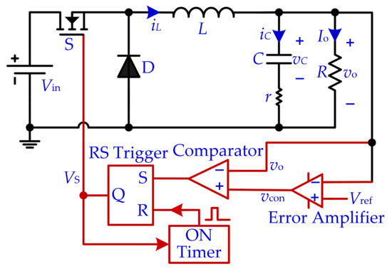
Figure 1.
Schematic diagram of V2-COT-controlled buck converter.
However, the stability and transient performance of the switching dc–dc converter with V2-COT control depends on the equivalent series resistor (ESR) of the output capacitor [14,15]. When a small output capacitor ESR is used, the converter operates in an unstable state and shows poor transient performance. When a large output capacitor ESR is used, the converter operates in a stable state and shows fast transient performance. However, large output capacitor ESRs cause large output voltage ripples, deteriorating the steady-state performance of the converter.
In the buck converter, capacitor current is the difference between the inductor current and load current. If the capacitor current is sensed as a feedback control signal, the change in the load current can be promptly fed back to the control circuit. The essence of V2 control with fast transient performance is that the output capacitor ESR is used to sense the capacitor current as the control signal for output voltage regulation [15]. Thus, using capacitor current as the compensation ramp can not only stabilize the V2-COT-controlled buck converter with small output capacitor ESR but can also improve its load transient performance [9]. In addition, some studies improved the load transient performance of the buck converter by introducing some auxiliary circuits during the transient operation; for instance, this was done by switching to a smaller inductor during the load transient operation [16] and by adding a load-side switched-capacitor-based converter during the load transient operation [17]. Although these auxiliary circuits can improve the load transient performance of a buck converter, they also make the circuit structures more space-consuming and complex. Thus, the improving control techniques in a simple way may be more effective and may represent practical solutions for most voltage regulator applications.
In general, from the point of view of feedback control signal, the sensing capacitor current as the feedback control signal of COT control, i.e., capacitor current COT (CC-COT) control, can achieve very fast transient performance [18,19]. However, the CC-COT control still suffers from transient response limitations. This is because when the load step-down occurs during an on-time interval, the COT controller cannot respond until the on-time expires [20]. This delay causes an additional output voltage overshoot. Specially, the case will be worse when the load step-down occurs at the beginning of the on-time. In [5], a hybrid COT mode was proposed, which could improve the load transient performance of the conventional COT control. However, it did not consider the above delay problem. To eliminate the effect of delay on the unloading transient performance, an effective scheme is to truncate on-time immediately when load step-down occurs [20]. Based on this idea, some methods are implemented [21,22,23]. In [21], Syed Bari et al. proposed a new control strategy based on the current-mode COT control, in which the derivative of the output voltage was used to monitor the load step-down and truncated the on-time. Furthermore, to avoid using an additional block of the derivative of the output voltage, an inverse charge COT control was proposed in [22]. The inverse-charge COT control employed the voltage difference of the sensed inductor current and the error voltage of the error amplifier to charge a capacitor. Then, the capacitor voltage was compared with a threshold voltage for detecting the point of load step-step and for truncating the on-time. In [23], the difference of the sensed inductor current and the output voltage of the error amplifier was compared with predefined thresholds to truncate the on-time when load step-down occurred. However, since the inductor current and capacitor voltage cannot be mutated, the methods in [22] and [23] could not truncate the on-time immediately, resulting in some delay. Therefore, it is necessary to further improve the detection speed [24].
To eliminate the delay when the load step-down occurs during the on-time interval, a load step-down detection circuit is proposed based on the CC-COT control, i.e., the improved CC-COT control, to obtain less output voltage overshoot. The rest of this paper is organized as follows. In Section 2, the stability and transient performance of buck converters with V2-COT control and CC-COT control are reviewed. In Section 3, the unloading transient performance limitation of CC-COT is illustrated and then the operation principle of the improved CC-COT control is discussed. In Section 4, a PSIM simulation circuit model of the improved CC-COT control is established to verify the feasibility of the proposed detection circuit. The conclusion is drawn in Section 5.
2. Review of Stability and Transient Performance of Two Control Techniques
In Figure 2, a schematic diagram of the CC-COT-controlled buck converter is given, in which the output capacitor current is sensed for output voltage regulation. In comparing the CC-COT control with the V2-COT control, the control circuit structure is the same except for the feedback control signal. The workflow of the CC-COT-controlled buck converter is demonstrated by Algorithm 1, where MOSFET represents the status of switch S; Diode represents the status of diode D; On means the on state; and the Off means the off state. The initial states of switch S and diode D are set as MOSFET = On and Diode = Off and then the buck converter begins to work. By comparing the sensed capacitor current RSiC with the control signal vcon, the status of S and D are switched.
| Algorithm 1: The Workflow of the CC-COT Control. |
| 1: MOSFET = On; Diode = Off; |
| 2: while 1 { |
| 3: MOSFET = On; Diode = Off; |
| 4: Delay TON; // TON is set by ON Timer |
| 5: If RSiC > vcon |
| 6: { MOSFET = Off; Diode = On; |
| 7: MOSFET = On; Diode = Off; |
| 8: } |
| 9: } |
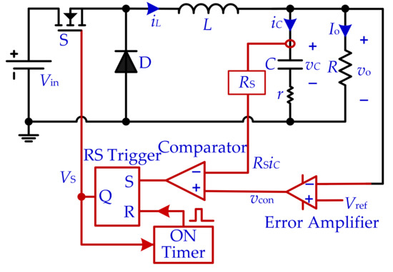
Figure 2.
Schematic diagram of the CC-COT-controlled buck converter.
For the case of small output capacitor ESR, the stability and transient performance for the buck converter with CC-COT control and V2-COT control are reviewed. Based on the schematic diagrams in Figure 1 and Figure 2, the corresponding PSIM simulation circuit models were established and the circuit parameters listed in Table 1 were chosen. In the both simulation circuit models, the error amplifier is implemented by the proportional-integral (PI) compensator with the same feedback gain g and time constant τ.

Table 1.
Circuit parameters for the two COT controls.
With the circuit parameters from Table 1, the steady-state simulation results for the buck converter with V2-COT control and CC-COT control are shown in Figure 3a,b, respectively. For the circuit parameters in Table 1, rC < 0.5TON, dissatisfying the stability condition of the V2-COT-controlled buck converter [15]. Thus, it operates in subharmonic oscillation with larger oscillation amplitudes of the inductor current and output voltage, as shown in Figure 3a. However, the CC-COT-controlled buck converter does not have this limitation and shows smaller oscillation amplitudes of the inductor current and output voltage, as shown in Figure 3b. It should be emphasized that, according to our previous research work [6], to ensure that the CC-COT-controlled buck converter operates in a stable state when rC < 0.5TON, the feedback gain of the PI compensator should meet the following stability conditions,
where κ = R/(R + r).
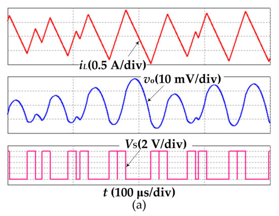
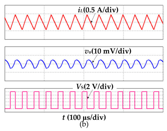
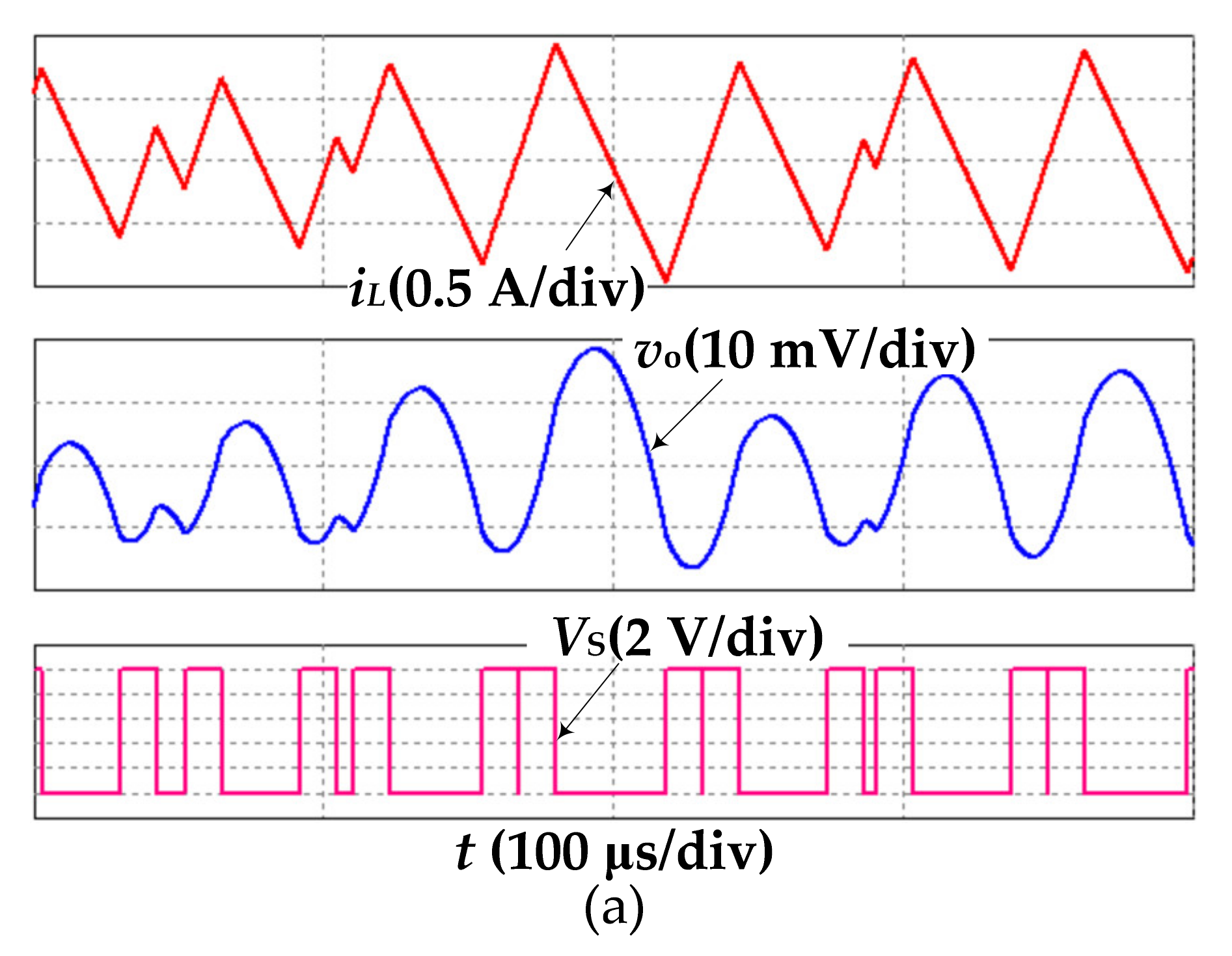
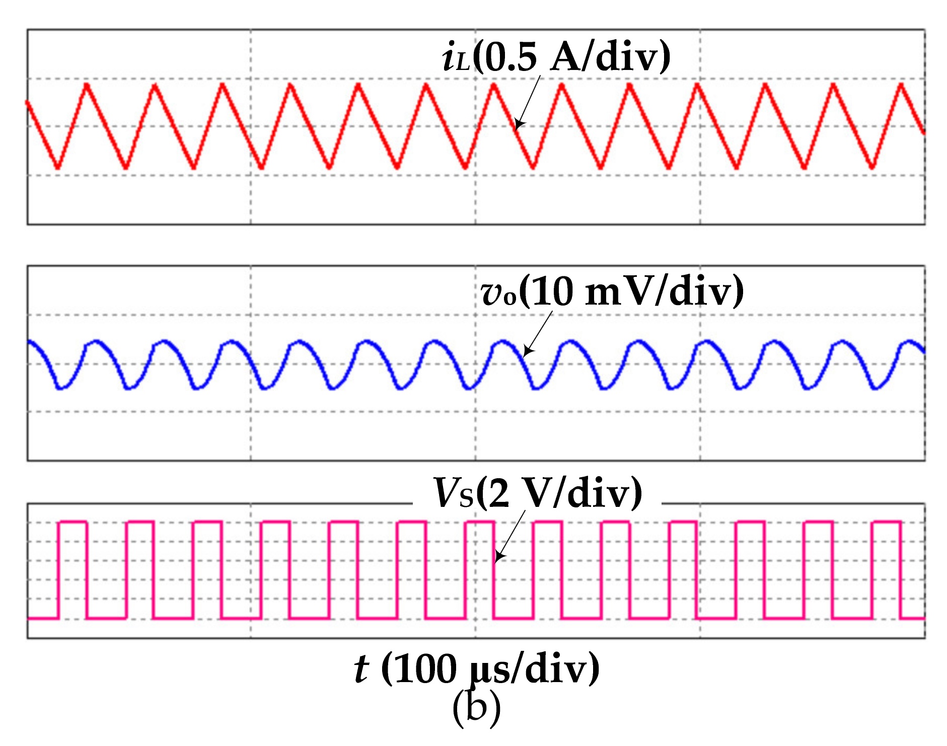
Figure 3.
Steady-state simulation results for two COT controls with output capacitor ESR r = 10 mΩ. (a) V2-COT control and (b) CC-COT control.
Furthermore, for the same circuit parameters used in Figure 3, the transient state simulation results of the buck converter with CC-COT control and V2-COT control are shown in Figure 4a,b, where the load current is switched to 7 A from 5 A and then back to 5 A. The comparison of the transient state performance for the two COT controls is given in Table 2.

Figure 4.
Transient state simulation results for two COT controls with output capacitor ESR r = 10 mΩ, where the load current is switched to 7 A from 5 A and then back to 5 A. (a) V2-COT control and (b) CC-COT control.
Table 2.
Transient performance comparison for V2-COT control and CC-COT control with the small output capacitor ESR.
3. Improved CC-COT Control for Buck Converter
3.1. Unloading Transient Performance Limitation of CC-COT Control
In the buck converter, when the load step-down occurs, the inductor current is expected to be immediately reduced to decrease the output voltage overshoot. However, if the load step-down occurs during the on-time, the COT controller cannot respond until the on-time expires, as shown in Figure 5. Thus, the inductor current continues to increase during the rest of the on-time and the additional charge Qa (yellow area) stored in the inductor is dumped in the output capacitor, causing the larger output voltage overshoot. Specially, the worst case can be triggered when the load step-down occurs at the beginning of the on-time.
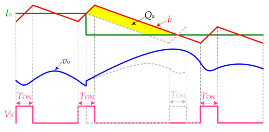
Figure 5.
Unloading transient performance limitation for COT controller.
3.2. Improved CC-COT Control
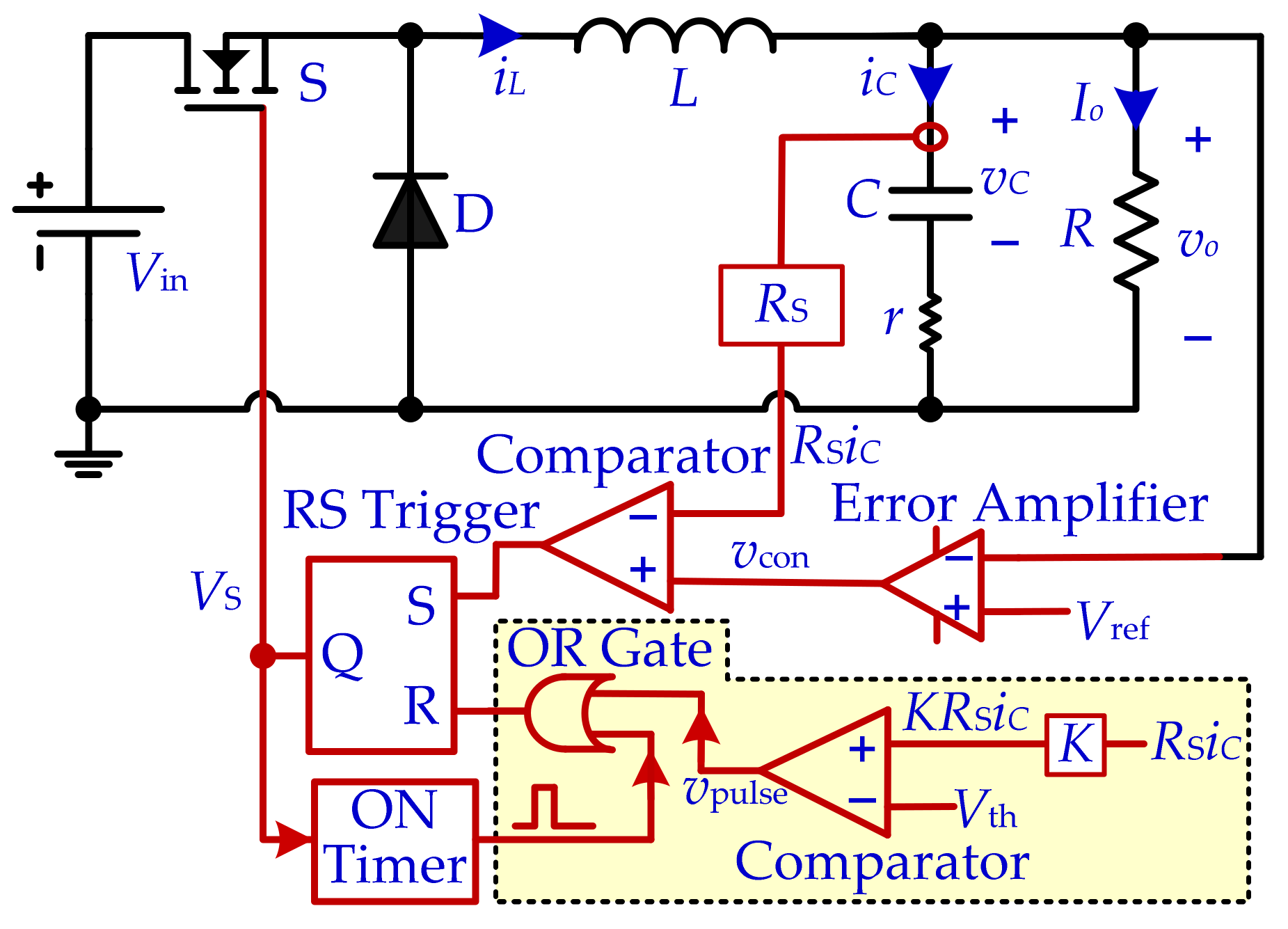
To overcome the unloading transient performance limitation of the COT controller, a load step-down detection circuit is proposed based on CC-COT control, i.e., improved CC-COT control. The schematic diagram of the improved CC-COT-controlled buck converter is shown in Figure 6. The detection circuit in the yellow area is composed of a comparator and an OR gate. The load step-down can be monitored by comparing the measured capacitor current KRSiC (K is the monitoring coefficient) with a preset threshold voltage Vth. Different from the CC-COT control, the reset signal of the RS trigger is jointly provided by the ON Timer and the detection circuit in the improved CC-COT control.
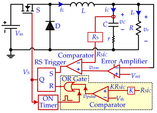
Figure 6.
Schematic diagram of the improved CC-COT-controlled buck converter.
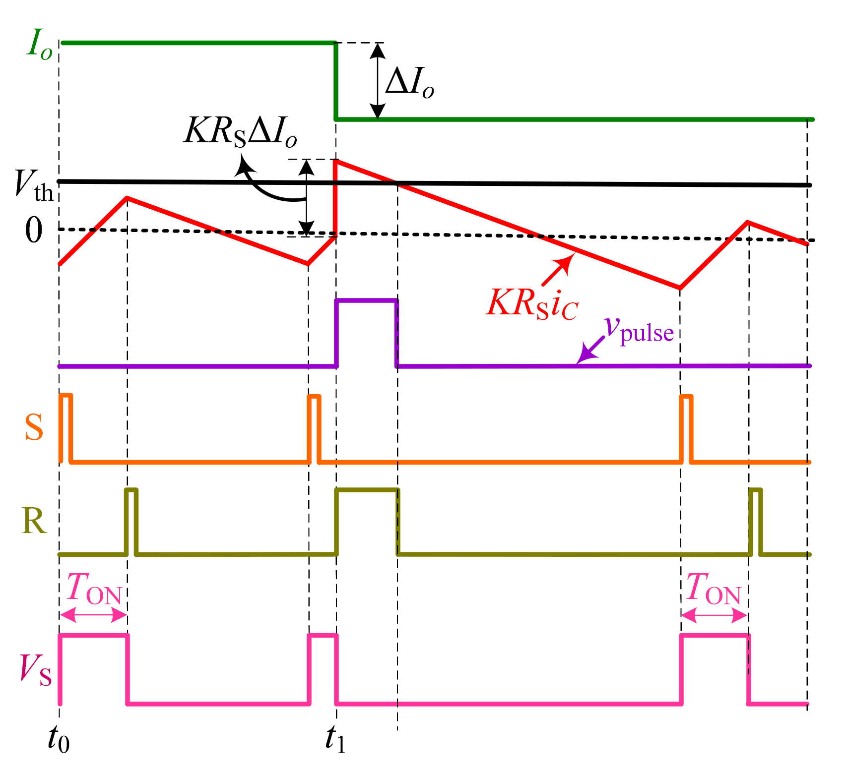
To elaborate on the operation mechanism of the detection circuit of the improved CC-COT control, the key operational waveforms of the control circuit for the load step-down are given in Figure 7, where Io is the load current, Vth is the preset threshold voltage, vpulse is the detection pulse, S and R are the set and reset signals of the RS trigger, and VS is the control pulse.
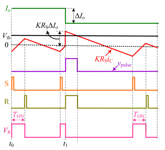
Figure 7.
Key operation waveforms of the control circuit in the improved CC-COT-controlled buck converter.
In steady-state, when RSiC decreases to the control signal vcon, the switch S is turned on and RSiC begins to increase. After fixed on-time TON, S is turned off by ON-Timer and RSiC begins to decrease. Once RSiC decreases to vcon, S is turned on again and a new switching cycle is initiated. KRSiC is always less than Vth and vpulse is low, and the on-time is only decided by the ON-Timer. Suppose that the load step-down with decreasing ΔIo occurs during the on-time; an increment voltage KRSΔIo is immediately produced in the measured capacitor current KRSiC. If KRSiC is greater than Vth, a detection pulse is promptly generated to reset the RS trigger and then turn off the switch S. According to the operation principle of the improved CC-COT control, the workflow of the improved CC-COT-controlled buck converter is demonstrated by Algorithm 2, where the actual on-time is decided by the ON Timer and by the relationship between KRSiC and Vth.
| Algorithm 2: Workflow of the Improved CC-COT Control. |
| 1: MOSFET = on; Diode = Off; |
| 2: while 1 |
| 3: if KRSiC < Vth |
| 4: MOSFET = on; Diode = Off; |
| 5: while t < TON // TON is set by ON Timer |
| 6: if KRSiC > Vth |
| 7: MOSFET = Off; Diode = On; |
| 8: break |
| 9: end |
| 10: t = t + 1; |
| 11: end |
| 12: if RSiC > vcon |
| 13: MOSFET = Off; Diode = On; |
| 14: end |
| 15: end |
| 16: if RSiC > vcon |
| 17: MOSFET = On; Diode = Off; |
| 18: else |
| 19: MOSFET = Off; Diode = On; |
| 20: end |
| 21: end |
3.3. Preset Threshold Voltage
In the improved CC-COT control, the threshold voltage Vth needs to be selected reasonably to ensure that the detection circuit is disabled in steady-state and is triggered instantly when the load step-down occurs during on-time.
Firstly, in order to ensure that the detection circuit is disabled for the steady-state, the preset threshold voltage Vth must be greater than the peak value of the sensed capacitor current in steady-state, i.e., Vth must satisfy
where m1 = (Vin − Vo)/L is the rising slope of the inductor current.
Secondly, to trigger the detection circuit instantly when the load step-down occurs during on-time, Vth needs to satisfy
where ton is the actual on-time of the switch S when the load step-down occurs during the on-time interval. Here, there are two special cases to be considered. One case is that ton = 0 μs, i.e., the load step-down occurs in the beginning of the on-time. Equation (3) can be rewritten as
Another case is that ton = TON, i.e., the load step-down occurs at the end of the on-time. Equation (3) can be rewritten as
Thirdly, there will still be a delay in the response of the COT controller if Vth falls within the following range.
It should be noted that the range (2)~(6) for the threshold voltage is based on the fact that ΔIo > m1(TON − ton). If ΔIo ≤ m1(TON − ton), the detection circuit is always disabled. However, the output voltage overshoot is small in this case, even though there is a delay, because the additional output voltage overshoot is proportional to the decrement of the load current [20].
3.4. Reduced Overshoot Output Voltage
When the output capacitor ESR can be ignored, the reduced output voltage overshoot of the improved CC-COT-controlled buck converter can be expressed as
Specially, if the load step-down occurs at the beginning of the COT interval, i.e., ton = 0 μs, the maximum reduced output voltage overshoot is written by
Thus, with the reduced output voltage overshoot, the amount of output capacitor can be significantly reduced in a practical design.
4. PSIM Circuit Simulation Verification
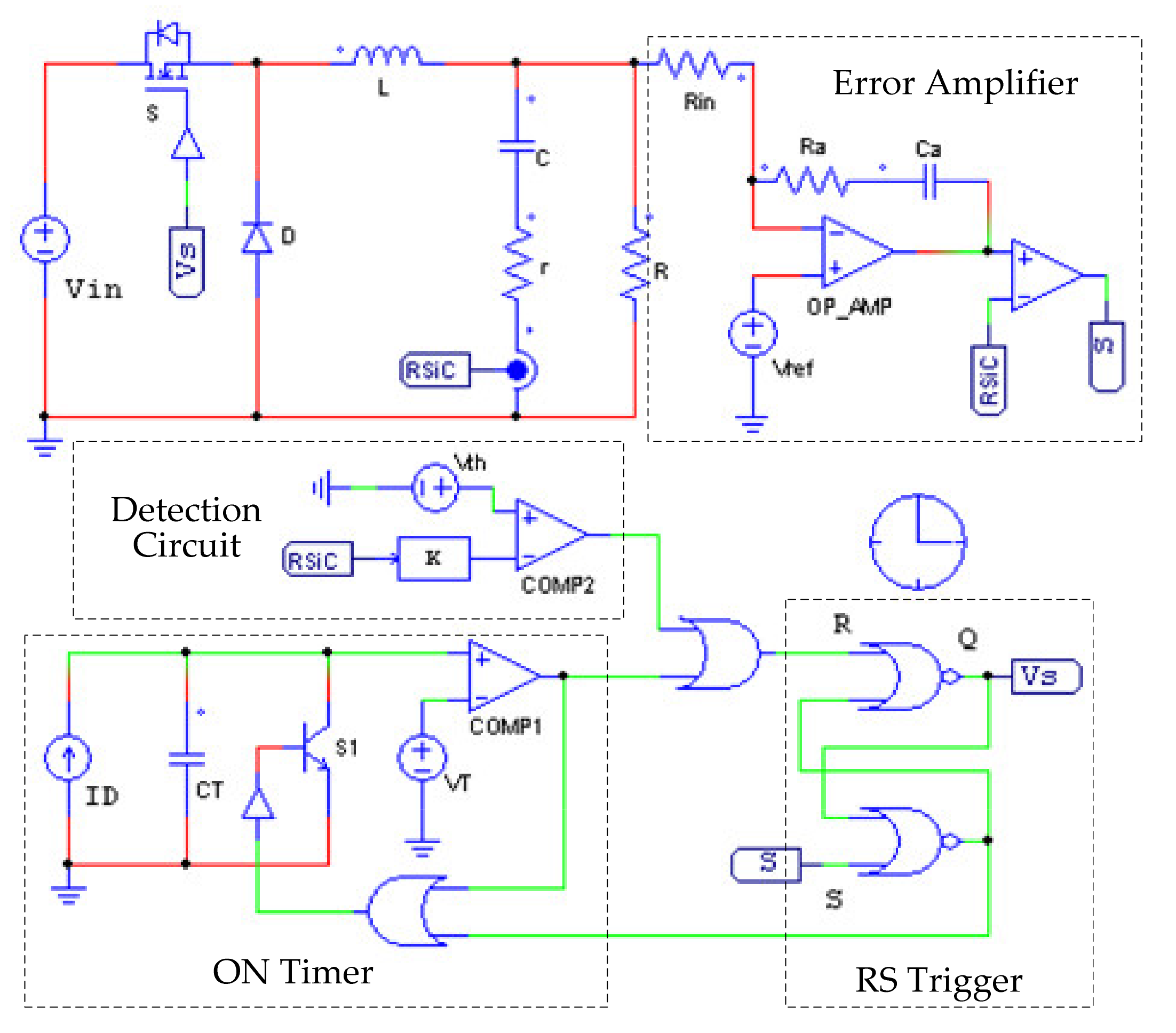
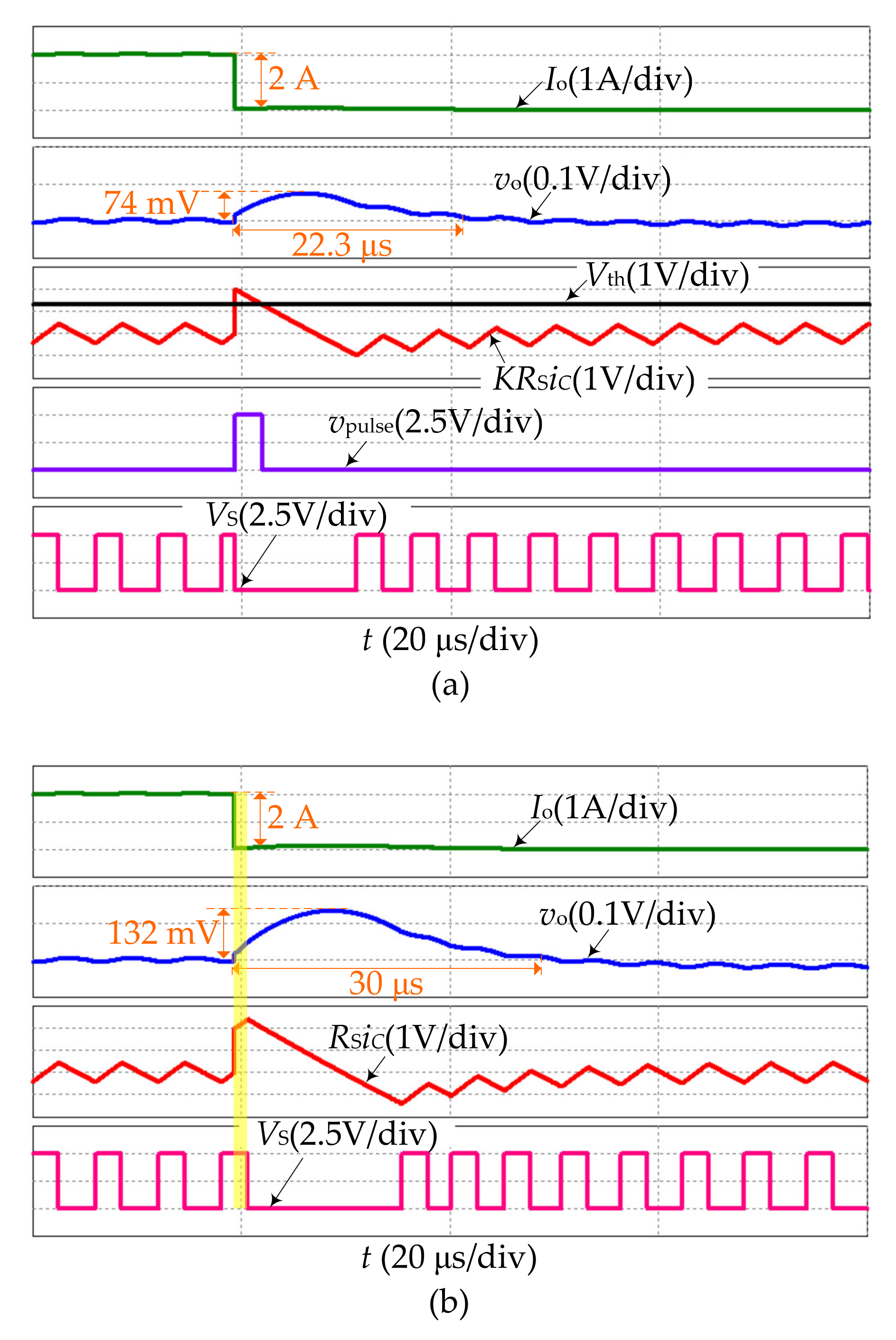
To demonstrate the fast unloading transient response benefited from the detection circuit, the PSIM simulation circuit model of the improved CC-COT-controlled buck converter, as shown in Figure 8, was built according to Figure 6. With the circuit parameters and load step-down ΔIo (load current is switched from 7 A to 5 A) used in Figure 4b, the range of the threshold voltage Vth with K = 1 and ton = 1.25 μs can be calculated from Equation (3) as 0.438 V < Vth < 2 V. Here, Vth is chosen as 1.3 V. The simulation waveforms of Io, KRSiC, Vth, vo, vpulse, and VS in the improved CC-COT-controlled buck converter are shown in Figure 9a. To contrast this, the simulation waveforms of Io, RSiC, vo, and VS in the CC-COT-controlled buck converter under the same circuit parameters are shown in Figure 9b.
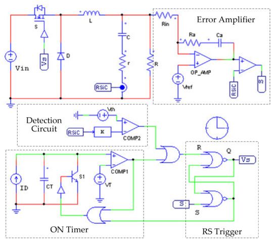
Figure 8.
The PSIM simulation circuit model of the improved CC-COT-controlled buck converter.
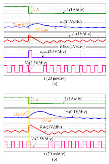
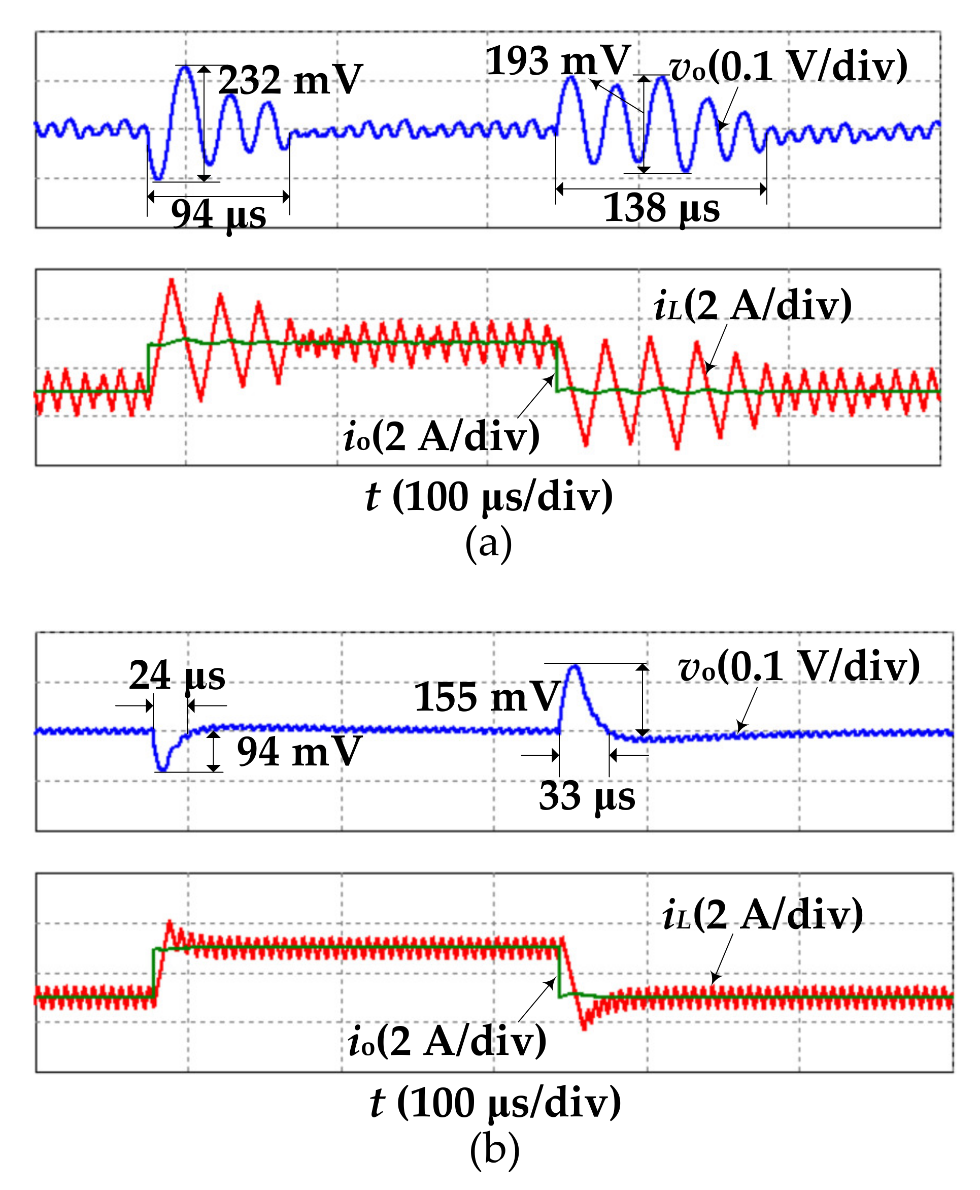
Figure 9.
Simulation waveforms for the buck converter with improved CC-COT control and the CC-COT control when the load step-down occurs during the on-time interval: (a) the improved CC-COT control and (b) the CC-COT control.
In Figure 9a, the measured capacitor current KRSiC is immediately greater than the preset threshold voltage Vth when the load step-down occurs during on-time. A detection pulse is promptly generated to truncate the on-time. The output voltage overshoot is 74 mV and the recovery time is 22.3 μs. In Figure 9b, the control circuit cannot respond until the constant on-time interval expires. The delay is marked with a light yellow area. The output voltage overshoot is 132 mV and the recovery time is 30 μs. Obviously, the output voltage overshoot and the recovery time of the improved CC-COT-controlled buck converter are significantly smaller than that of the CC-COT-controlled buck converter. It is indicated that the unloading transient response of the CC-COT-controlled buck converter is very much enhanced by introducing the detection circuit.
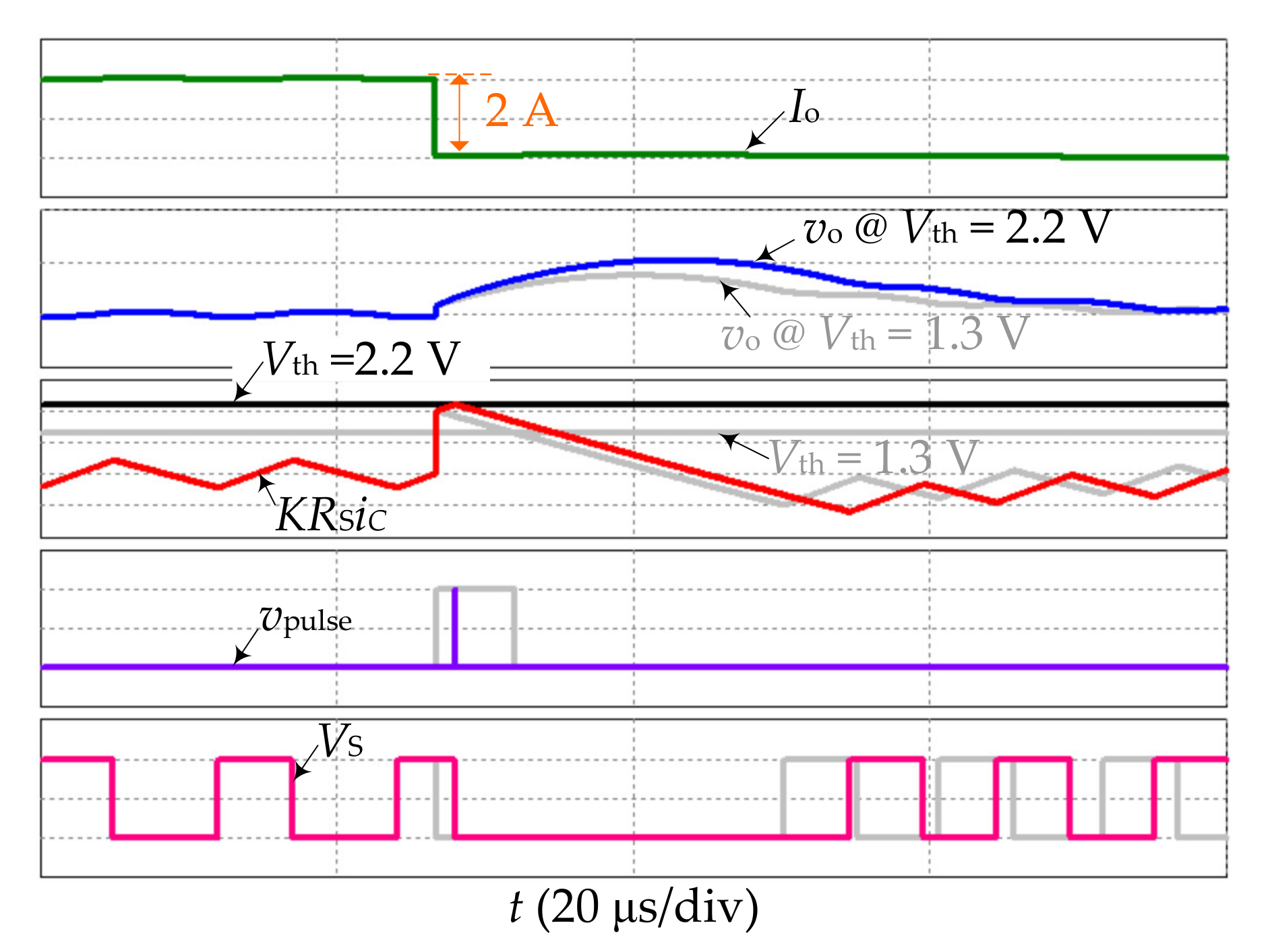
Additionally, for Vth = 2.1 V satisfying Equation (6), the simulation waveforms of Io, KRSiC, Vth, vo, vpulse, and VS in the improved CC-COT-controlled buck converter are shown in Figure 10. Obviously, there is still a delay in the response of the control circuit, causing a larger output voltage overshoot than that for Vth = 1.3 V satisfying Equation (3).
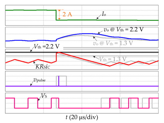
Figure 10.
Simulation waveforms for improved CC-COT-controlled buck converter with Vth = 2.2 V.
5. Comparison Results and Application Analysis
In this section, some comparisons are made to illustrate the validity of the improved CC-COT control proposed in this paper. Then, the application analysis is given.
For comparison in the same case, the buck converter in Figure 8 is replaced with a synchronous buck converter. Then, the fixed-circuit parameters for comparison are chosen in Table 3.
Table 3.
Fixed-circuit parameters of the improved CC-COT-controlled buck converter for comparison.
In [17], a load-side switched-capacitor-based converter was added to the buck converter, which significantly improved the load transient performance. Thus, the comparisons of this work with that in [17] can be made using the circuit parameter configurations given in [17]. The comparison results are listed in Table 4.
Table 4.
Comparison with Reference [17].
From Table 4, the load transient performance of the work in this paper is worse than that of [17] in terms of the loading/unloading recovery time and undershoot/overshoot voltage. However, it must be noted that the auxiliary circuit in [17] could make the circuit architecture more space-consuming and complex. Additionally, the digital control is needed to ensure the operation of the auxiliary circuit, which will increase the cost of the control. Considering the improved CC-COT control is an analog control and does not need any auxiliary circuit, there are no such problems. Therefore, in the actual application, the designer needs to choose the appropriate scheme according to the actual situation.
Another comparison can be made to further prove the validity of the proposed method in this paper. In [5], a hybrid constant on-time mode is proposed by introducing the dynamic reference voltage method and a proportional differential (PD) module into the voltage-mode COT control, which can achieve fast load transient performance. With the circuit parameter configurations in [5], the comparison can be made and the results are listed in Table 5.
Table 5.
Comparison with Reference [5].
From Table 5, the load transient performance of the work in this paper shows to be better than that of [5] in terms of the loading/unloading recovery time and undershoot/overshoot voltage. In addition, the ripple voltage of this work is much smaller than that in [5].
Through the comparisons, it can be concluded that in terms of improving control technologies to improve the load transient performance, the main performance indexes of the method in this paper are competitive and the method is reasonable. Meanwhile, in the simulations and comparisons, all the circuit parameter values are chosen in normal ranges, which means that our method can be implemented physically.
6. Conclusions
In this paper, an improved CC-COT control is proposed by introducing a detection circuit for monitoring the load step-down. Thus, once the load step-down occurs, the detection pulse is immediately generated to truncate the on-time and turn off the switch. Consequently, the additional output voltage overshoot caused by the delay is effectively eliminated. The results indicate that the improved CC-COT control has no unloading transient performance limitation. Furthermore, the range of the threshold voltage and the maximum reduced output voltage overshoot are derived as well. With the detection circuit proposed in this paper, the amount of output capacitor can be significantly reduced in a practical design of the COT controller. The proposed control method is suitable for applications requiring the fast load transient response, such as the voltage regulation module for powering the microprocessor, the point-of-load converter, and so on.
Author Contributions
Conceptualization, X.Z.; methodology, B.B.; software, T.W.; validation, X.Z., T.W. and B.B.; formal analysis, X.Z.; investigation, T.W.; resources, B.B.; data curation, X.Z.; writing—original draft preparation, X.Z.; writing—review and editing, B.B. and T.W.; visualization, X.Z. and T.W.; supervision, B.B.; project administration, X.Z.; funding acquisition, X.Z. All authors have read and agreed to the published version of the manuscript.
Funding
This research study was funded by the China Postdoctoral Science Foundation, grant number 2020M671291; by Jiangsu Planned Projects for Postdoctoral Research Funds, grant number 2020Z103; and by the Postgraduate Education Reform Projects of Jiangsu Province, grant number KYCX21_2821.
Conflicts of Interest
The authors declare no conflict of interest.
References
- Ming, X.; Xin, Y.L.; Li, T.S.; Liang, H.; Li, Z.J.; Zhang, B. A constant on-time control with internal active ripple compensation strategy for buck converter with ceramic capacitors. IEEE Trans. Power Electron. 2019, 34, 9263–9278. [Google Scholar] [CrossRef]
- Zhang, X.; Zhang, Z.W.; Bao, H.; Bao, B.C.; Qu, X.H. Stability effect of control weight on multiloop COT-controlled buck converter with PI compensator and small output capacitor ESR. IEEE J. Emerg. Sel. Top. Power Electron. 2021, 9, 4658–4667. [Google Scholar] [CrossRef]
- Xie, F.; Yang, R.; Zhang, B. Bifurcation and border collision analysis of voltage-mode-controlled flyback converter based on total ampere-turns. IEEE Trans. Circuits Syst. I Regul. Pap. 2011, 58, 2269–2280. [Google Scholar] [CrossRef]
- Zhou, G.H.; Xu, J.P.; Wang, J.P. Constant-frequency peak-ripple-based control of buck converter in CCM: Review, unification, and duality. IEEE Trans. Ind. Electron. 2014, 61, 1280–1291. [Google Scholar] [CrossRef]
- Zhong, S.; Shen, Z.Q. A hybrid constant on-time mode for buck circuits. Electronics 2021, 10, 930. [Google Scholar] [CrossRef]
- Zhang, X.; Xu, J.P.; Wu, J.H.; Bao, B.C.; Zhou, G.H.; Zhang, K.T. Reduced-order mapping and design-oriented instability for constant on-time current-mode controlled buck converters with a PI compensator. J. Power Electron. 2017, 17, 1298–1307. [Google Scholar]
- Intel Core. Intel Core Duo Processor and Intel Core Solo Processor Datasheet, Intel Document Number: 309221-004; Intel Core: Santa Clara, CA, USA, 2006. [Google Scholar]
- Tian, S.L.; Lee, F.C.; Mattavelli, P.; Cheng, K.Y.; Yan, Y.Y. Small-signal analysis and optimal design of external ramp for constant on-time V2 control with multilayer ceramic caps. IEEE Trans. Power Electron. 2014, 29, 4450–4460. [Google Scholar] [CrossRef]
- Yan, Y.Y.; Lee, F.C.; Tian, S.L.; Liu, P.H. Modeling and design optimization of capacitor current ramp compensated constant on-time V2 control. IEEE Trans. Power Electron. 2018, 33, 7288–7296. [Google Scholar] [CrossRef]
- Wang, J.P.; Xu, J.P.; Bao, B.C. Analysis of pulse bursting phenomenon in constant-on-time-controlled buck converter. IEEE Trans. Ind. Electron. 2011, 58, 5406–5410. [Google Scholar] [CrossRef]
- Qian, T. Subharmonic analysis for buck converters with constant on-time control and ramp compensation. IEEE Trans. Ind. Electron. 2013, 60, 1780–1786. [Google Scholar] [CrossRef]
- Zhang, X.; Bao, B.C.; Bao, H.; Wu, Z.M.; Hu, Y.H. Bi-stability phenomenon in constant on-time controlled buck converter with small output capacitor ESR. IEEE Access 2018, 6, 46227–46232. [Google Scholar] [CrossRef]
- Lin, Y.C.; Chen, C.J.; Chen, D.; Wang, B. A ripple-based constant on-time control with virtual inductor current and offset cancellation for DC power converters. IEEE Trans. Power Electron. 2012, 27, 4301–4310. [Google Scholar] [CrossRef]
- Wang, J.P.; Bao, B.C.; Xu, J.P.; Zhou, G.H.; Hu, W. Dynamical effects of equivalent series resistance of output capacitor in constant on-time controlled buck converter. IEEE Trans. Ind. Electron. 2013, 60, 1759–1768. [Google Scholar] [CrossRef]
- Li, J.; Lee, F.C. Modeling of V2 current-mode control. IEEE Trans. Circuits Syst. I Regul. Pap. 2010, 57, 2552–2563. [Google Scholar] [CrossRef]
- Lu, D.D.-C.; Liu, J.C.P.; Poon, F.N.K.; Pong, B.M.H. A single phase voltage regulator module (VRM) with stepping inductance for fast transient response. IEEE Trans. Power Electron. 2007, 22, 417–424. [Google Scholar] [CrossRef] [Green Version]
- Kirshenboim, O.; Cervera, A.; Peretz, M.M. Improving loading and unloading transient response of a voltage regulator module using a load-side auxiliary gyrator circuit. IEEE Trans. Power Electron. 2017, 32, 1996–2007. [Google Scholar] [CrossRef]
- Zhang, X.; Xu, J.P.; Zhou, G.H.; Chen, Y.M. Capacitor Current Fixed off-Time Control for Buck Converter with Fast Response and Output Capacitor ESR Independence; IEEE IPEMC-ECCE Asia: Hefei, China, 2016. [Google Scholar]
- del Viejo, M.; Alou, P.; Oliver, J.A.; García, O.; Cobos, J.A. Fast Control Technique Based on Peak Current Mode Control of the Output Capacitor Current; IEEE ECCE: Atlanta, GA, USA, 2010. [Google Scholar]
- Cortés, J.; Šviković, V.; Alou, P.; Oliver, J.A.; Cobos, J.A. Improved transient response of controllers by synchronizing the modulator with the load step: Application to V2Ic. IEEE Trans. Power Electron. 2015, 30, 1577–1590. [Google Scholar] [CrossRef] [Green Version]
- Bari, S.; Li, Q.; Lee, F.C. A new fast adaptive on-time control for transient response improvement in constant on-time control. IEEE Trans. Power Electron. 2018, 33, 2680–2689. [Google Scholar] [CrossRef]
- Bari, S.; Li, Q.; Lee, F.C. Inverse charge constant on-time control with ultrafast transient performance. IEEE J. Emerg. Sel. Top. Power Electron. 2021, 9, 68–78. [Google Scholar] [CrossRef]
- Texas Instruments, TPS53625 Datasheet. Available online: www.ti.com (accessed on 20 August 2021).
- Qu, Y.; Shu, W.; Kang, Y.; Chang, J.S. A 30 V 2 A Real-Time Programmable Solid-State Circuit Breaker with Improved Detection-Speed and Enhanced Power-Efficiency; IEEE ESSCIRC: Cracow, Poland, 2019. [Google Scholar]


Publisher’s Note: MDPI stays neutral with regard to jurisdictional claims in published maps and institutional affiliations. |
© 2021 by the authors. Licensee MDPI, Basel, Switzerland. This article is an open access article distributed under the terms and conditions of the Creative Commons Attribution (CC BY) license (https://creativecommons.org/licenses/by/4.0/).