Article

Optimization of TSV Leakage in Via-Middle TSV Process for Wafer-Level Packaging

1
School of Microelectronics, Fudan University, Shanghai 200433, China
2
Semiconductor Manufacturing Electronics (Shaoxing) Corporation, Shaoxing 312035, China
3
National Integrated Circuit Innovation Center, Shanghai 201203, China
*
Author to whom correspondence should be addressed.
Electronics 2021, 10(19), 2370; https://doi.org/10.3390/electronics10192370
Submission received: 28 August 2021 / Revised: 17 September 2021 / Accepted: 22 September 2021 / Published: 29 September 2021
(This article belongs to the Section Microelectronics)

Abstract

:
Through silicon via (TSV) offers a promising solution for the vertical connection of chip I/O, which enables smaller and thinner package sizes and cost-effective products by using wafer-level packaging instead of a chip-level process. However, TSV leakage has become a critical concern in the BEOL process. In this paper, a Cu-fulfilled via-middle TSV with 100 µm depth embedded in 0.18 µm CMOS process for sensor application is presented, focusing on the analysis and optimization of TSV leakage. By using etch process, substrate defect, and thermal processing co-optimization, TSV leakage failure can be successfully avoided, which can be very instructive for the improvement in TSV wafer-level package yield as well as device performance in advanced semiconductor technology.

1. Introduction

Recently, smart mobile terminals have continuously driven the scaling of packaging density, especially in the vertical dimension with lowered power consumption and improved system bandwidth [1,2,3,4]. Through silicon via (TSV) technology has become attractive as a potential solution to further extend Moore’s law through vertical connection to realize boosts in system performance and integration density while maintaining acceptable fabrication costs using wafer-level packaging [5]. Various studies have shown the process readiness of 2.5D Si interposer [6,7,8] or embedded TSV as wide I/O [9], although low-volume TSV technology is from via-last wafer-level packaging, which uses TSV with partial metal filling [10,11]. Although this is a more cost-effective wafer-level packaging solution, it is not suitable for implementation in applications such as sensors, RF, and power devices that require good signal quality, robust reliability, and acceptable fabrication costs under squeezed package sizes (both for planar format and vertical thickness). So, Cu-fulfilled via-middle TSV [12] is a promising approach to enable rewiring from the topside to the backside within a certain thickness and consequently enables the use of wafer-level packaging, which significantly drops package costs compared to chip-level assembly. However, with the downscaling of FEOL device size and increased device density, TSV size is shrinking rapidly, and current leakage can easily occur with smaller TSV sizes, leading to TSV failure.
TSV leakage has been theoretically studied, and its dependence and relation to parameters such as temperature and stress have also been investigated [13,14,15]. Nevertheless, optimizations in the via-middle TSV fabrication process to suppress TSV leakage using wafer-level packages remain elusive. Via-middle TSV is made from the front side and drilled into silicon with a certain depth. It is embedded and isolated from one another since its bottom is surrounded by silicon. The TSV bottom is revealed by backside grinding and connected by metallization. So, the TSV depth is around 100 µm to enable backside reveal process robustness with enough Si thickness (>100 µm) after grinding. In addition, the TSV hole size should be larger than 10 µm according to the TSV etch/filling capability with about a 10:1 aspect ratio. This is where a leakage path can be formed in most cases with non-ideal TSV etching followed by Cu filling. In this work, we studied the origins of the TSV leakage, focusing on the TSV etch process parameters and the intrinsic defects in Si substrate used for fabrication. In addition, we found that the film stress introduced during thermal processing after TSV formation also plays a critical role in TSV leakage. By using etch process, substrate defect, and thermal processing co-optimization, TSV leakage failure can be effectively suppressed, and such approaches also present a promising solution for a reliable via-middle TSV embedded in CMOS for wafer-level packaging.

2. Experimental Section

In this work, a via-middle TSV was embedded into standard 0.18 µm CMOS platforms. First, TSV holes with 13 µm width were drilled using Bosch etch process to 100 µm in depth after front-end device and tungsten contact formation. Different etch conditions were carried out to study the impact of the etching process on device leakage. Condition 1 is the standard baseline process, while condition 2 and condition 3 are experimental splits adjusting the time of deposition, clean and etch steps, as well as the gas flow rate of SF6 in deposition step and C4F8 in the clean and etch steps. Table 1 and Figure 1 show and compare the splits with detailed process parameters.
After TSV etching, a thick oxide isolation layer was formed on the TSV sidewall, followed by the deposition of a Ta/TaN barrier layer and Cu seed using physical vapor deposition (PVD). After that, bottom-up plating of Cu was carried out employing an Applied Materials (AMAT) radius-S tool. Then, a thermal annealing process at low temperatures was carried out to enable Cu growth and release stress. The Cu overburden was removed by chemical-mechanical planarization (CMP). The subsequentially first metal layer of Al/Ta/TaN was formed on top of the Cu TSV, followed by the standard backend metal routing process. After the front side process was completed, the CMOS wafer with the buried TSV was turned over and taped on a carrier to be ground until the TSV hole was exposed from the bottom side. The Si recess with low-temperature isolation film was then filled and followed by bumping the redistribution layer (RDL).
The TSV leakage was tested with the structure shown in Figure 2 using an Agilent HP4072A. The TSV morphology was observed using an optical microscope, and the cross-section was prepared and characterized using a focused ion beam (FIB; FEI450) tool and scanning electron microscope (SEM; HITACHI-9220). The TSV crystallization was analyzed using a transmission electron microscope (TEM). Each datum demonstrated in this manuscript was obtained from more than 5 samples.

3. Results and Discussion

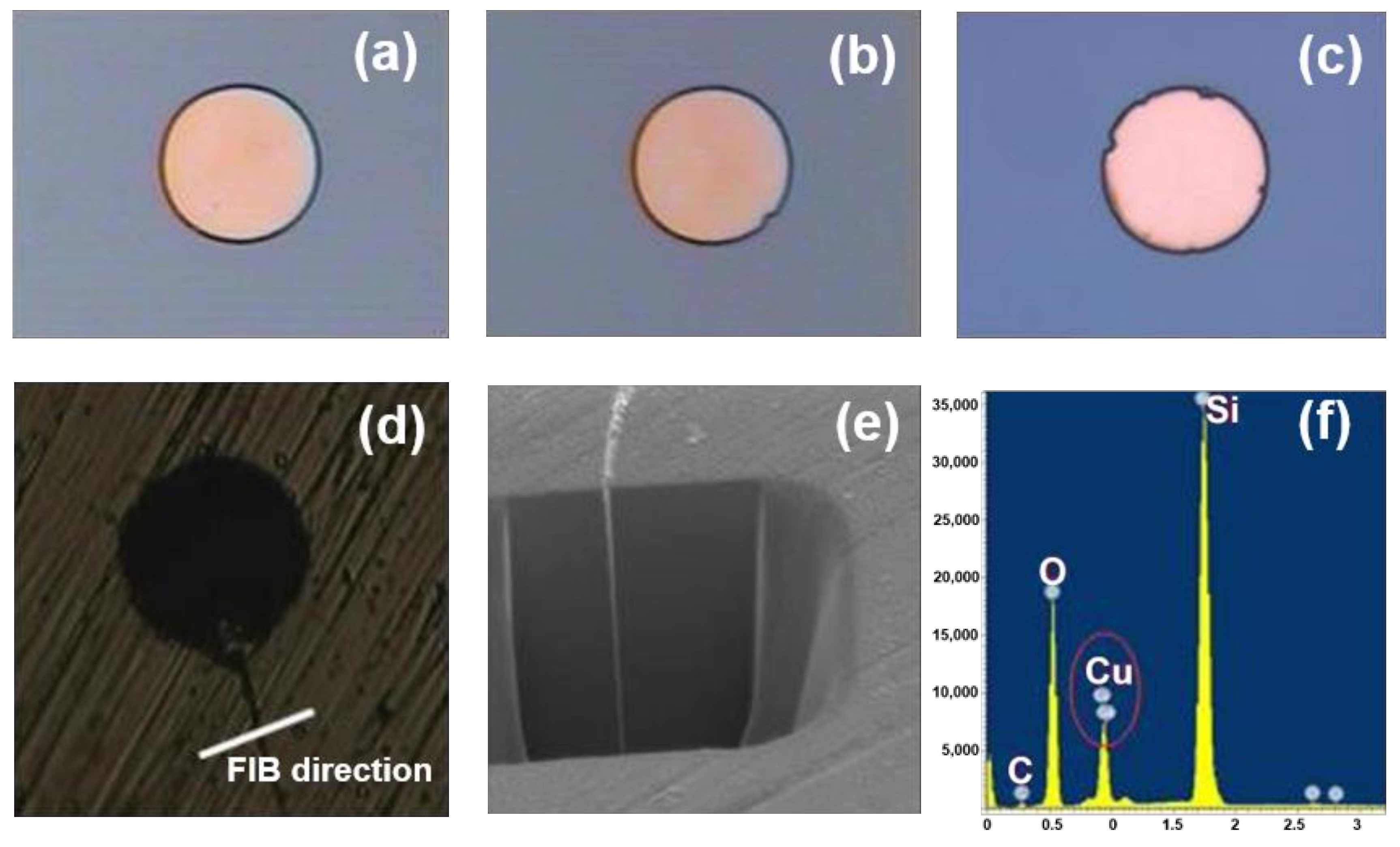
Figure 3 shows the images and characterizations comparing ideal TSV samples and TSV with leakage after RDL removal. Figure 3a exhibits a good sample with a perfect circle-shaped TSV bottom, and non-ideal samples with defects such as small notches at the fringe are illustrated in Figure 3b,c. In some cases, a slight crack was observed along the notch, as shown in Figure 3d, after Cu removal by dipping in acid and cutting by FIB. By measuring the cross-section (Figure 3e) and elemental composition (Figure 3f) by FIB and EDX, respectively, Cu was found in the crack, leading to TSV leakage, which was attributed to the non-ideal TSV etch process and the intrinsic defects in the Si substrate used for fabrication.
Through the FIB check on the non-grinded wafer, one delamination was found in the TSV bottom, as shown in Figure 4. Cu/Ta/TaN metal layers were separated from the Si/SiOx isolation layer below, and a slit formed, which led to a crack such as that shown in Figure 3d during the backside grind process. Cu thus diffused in, and a leakage path formed. Such delamination was caused by the mismatch of the coefficients of thermal expansion (CTE) between Cu/Ta/TaN and Si/SiOx. Therefore, thermal stress is another factor to be controlled to avoid TSV leakage, which was also systematically analyzed and optimized in our work.

3.1. TSV Leakage Caused by TSV Etch Process

The Bosch etch process is widely used in TSV fabrication due to its advantages of a high aspect ratio and straight TSV profile. Deposition and etch steps were performed subsequently. SF6 plasma was used to etch silicon during a brief etch step (Equation (1)), after which C4F8 plasma was used to deposit a passivation layer (Equation (2)) on all surfaces.
SF6 + Si → SiF (gas) + S
C4F8 + Si → SiF (gas) + C
The passivation coated on the sidewalls of TSV with a polymer inhibited the chemical reaction and stopped the etching in the lateral direction. The passivation layer was then etched away from the horizontal surfaces by ionic bombardment, allowing the etch process to continue downward. Although such multistep processes enhanced the anisotropy of the etching [16,17], the complexity and mechanism still remain elusive, leading to inefficient optimization and, hence, a poor TSV etch profile.
By carrying out the splits detailed in Table 1, we compared the TSV morphology and profiles after etching. Figure 5a,b shows the cross-section profile and the TEM image focusing on the TSV bottom using condition 1, respectively. Clear striations were observed. Under condition 2, the via had fewer striations (Figure 5c,d), and ideal via characteristics were obtained using condition 3 (Figure 5e,f).
The electrical characteristics of TSV under three conditions were also compared. As shown in Figure 6, TSV under both condition 1 and condition 2 showed leakage fail points, while no leakage occurred under condition 3. Similar experimental results were obtained from multiple test wafers. This is consistent with the SEM results in Figure 5, further confirming the effect on the electrical performance through etch process optimization.
The TSV bottom notch observed in Figure 3 was actually due to the formation of striations in the TSV shown in Figure 5 under condition 1 and condition 2. The precursor reactions are C4F8 + Si → SiF(gas) + C in the deposition step, and SF6 + Si → SiF(gas) + S in the etch step. The polymer blocks etching and functions as a protecting layer to avoid sidewall etching. However, a high volume of polymer leads to residue or micro-mask during the etch step and forms the aforementioned striations. Increasing SF6 gas at the etch step is slightly helpful for removing the polymer, while increasing C4F8 at the deposition step can strengthen the polymer protection at the sidewall, which was confirmed by condition 2 and condition 3. This was good for shaping the profile compared to that under condition 1. On the other hand, although shortening the deposition and etch step duration enables a faster cycle, less polymer deposition degrades the control over the balance between polymer removal and polymer protection. Insufficient polymer protection can easily lead to Si grass or over-etch, as shown in the results in condition 2, with slight grass found at small scallops along the TSV sidewall. In comparison, increasing the deposition step time with sufficient polymer protection enabled a stable and grass/striation-free scallop that was obtained by condition 3.

3.2. TSV Leakage Caused by Substrate Bulk Micro Defect (BMD)

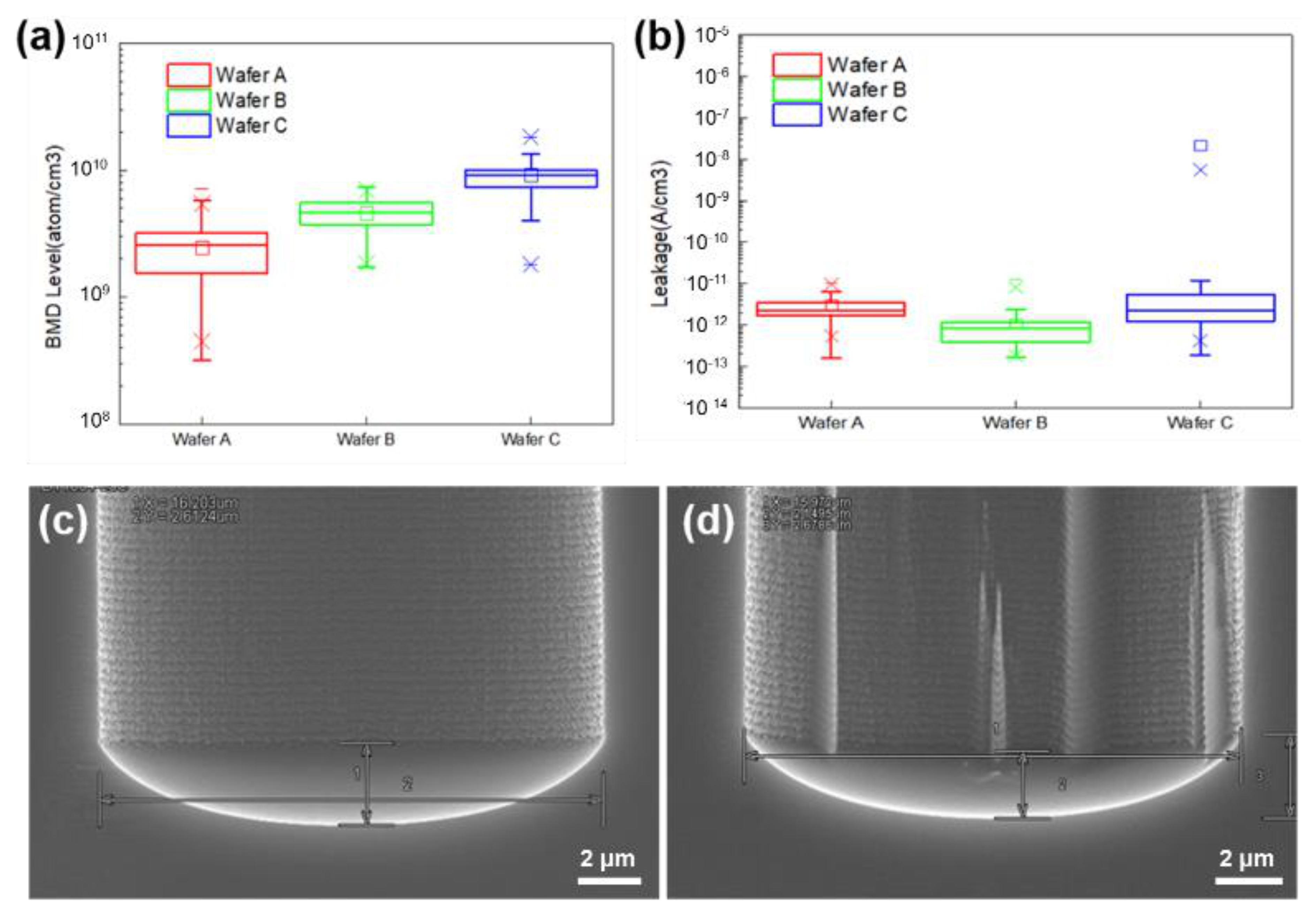
Despite the defects introduced during the etching process, the TSV quality was also impacted by the intrinsic defect of the Si used for fabrication. The bulk micro defect (BMD) density in Si substrates can be fatal during via formation, generating additional striations. Based on the TSV etch process with condition 3, the influence of BMD density on the TSV process was also experimentally studied, and two groups of substrate wafers with different BMD levels were used, as shown in Figure 7a: wafers A and B with a BMD level of about 109 atom/cm3, and wafer C with a BMD level of about 1010 atom/cm3. The TSV etch on both wafers A and B showed no striation profile, which, on the contrary, appeared during TSV formation after the FEOL device process on wafer C with a higher BMD level (cross-section SEM images shown in Figure 7c,d). Thus, it was anticipated that leakage would occur, which was further experimentally confirmed.
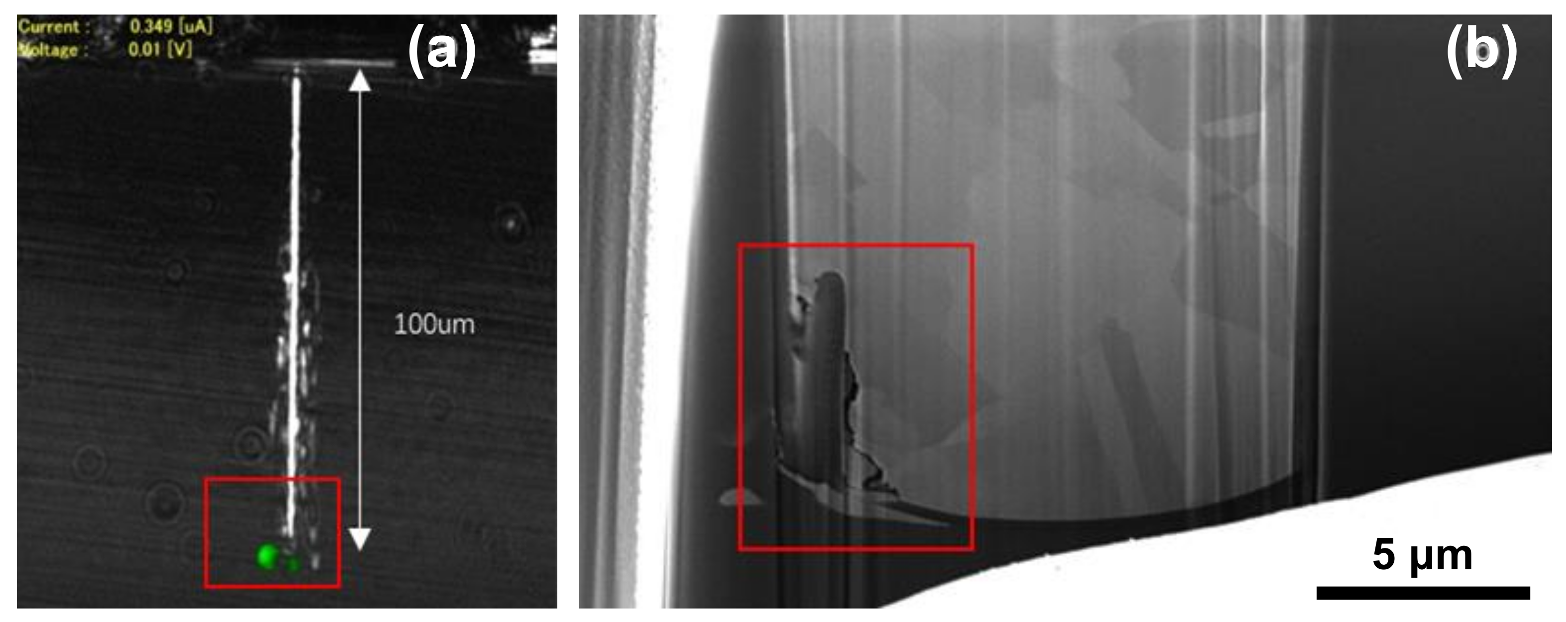
As shown in Figure 7b, the leakage fail point was only observed on wafer C, while wafers A and B were free of leakage failure. Further failure analysis was performed on the failed sample on wafer C. A precise cut was made beside the TSV, and then OBIRCH was performed to obtain the hot spot. As shown in Figure 8, hot spots were found at the TSV bottom (Figure 8a), and Cu diffusion was also found at the hot spot from the FIB cross-section, which is shown in Figure 8b.
It is known that the BMD layer serves as an intrinsic gathering layer to improve device layer impurity and device performance [18], which makes it indispensable in Si-based processes. However, the correlation between the BMD density and Si striation in a silicon substrate clearly suggests that BMD is a critical factor that should be addressed and optimized in TSV wafer-level packaging. In the manufacturing of bare Si wafers, there is one final annealing step involved with the purpose of minimizing defect density. Nevertheless, these defects are released and re-gathered if the wafer undergoes additional high-temperature processing (e.g., >600 °C), and serve as micro-masks during etching and result in silicon striation defects at the TSV bottom. Considering the fact that the TSV process is defined after device fabrication and tungsten contact loop, no high-temperature processes are applied to the wafer afterward. Therefore, the experimental results shown in this section indicate that in order to effectively control the failure rate of advanced silicon structures such as Si fins, a substrate with low BMD density is preferred to improve the via-middle TSV embedded CMOS device.

3.3. TSV Leakage Caused by Stress Variation

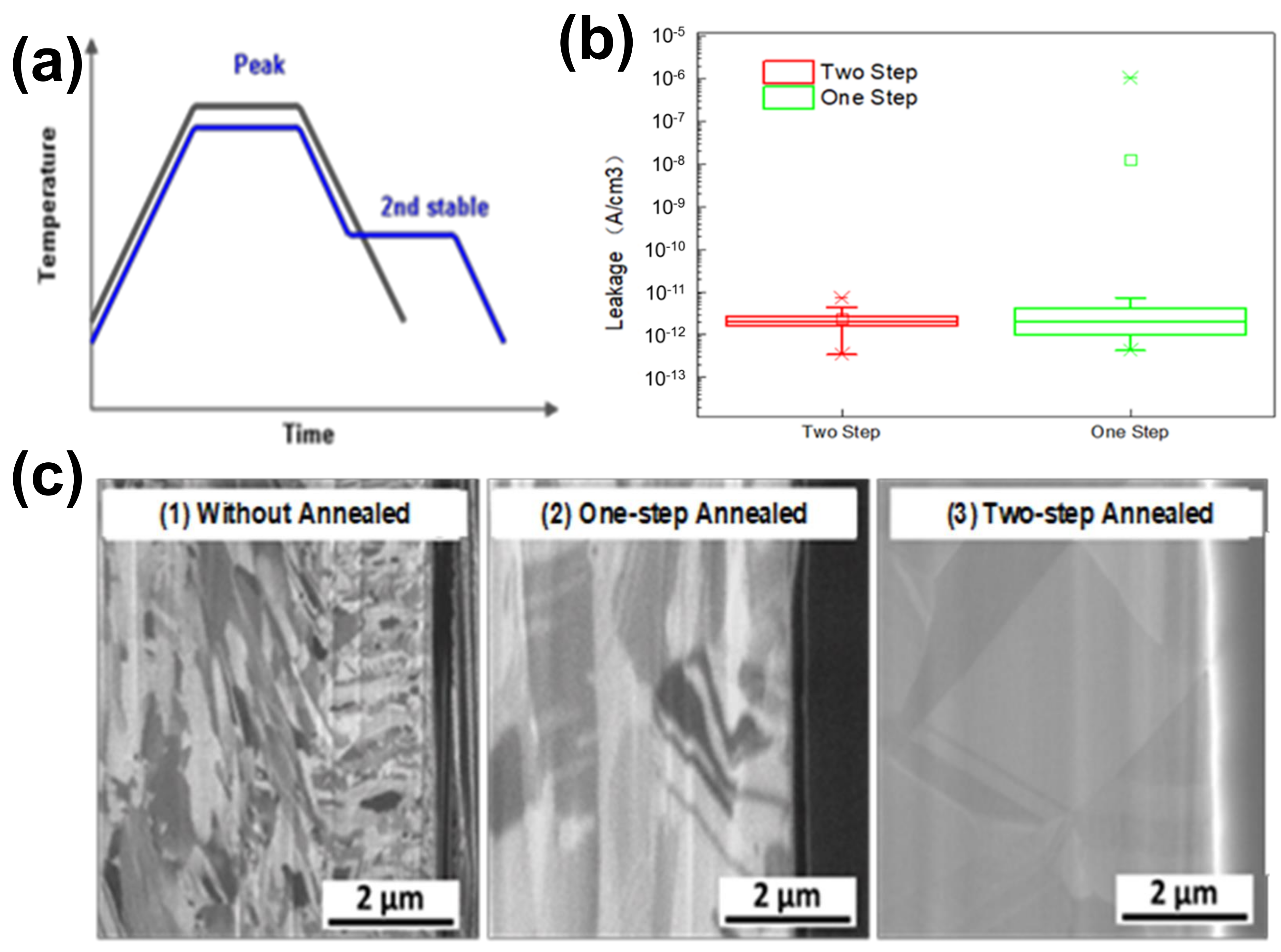
As mentioned in the previous section, the substrate does not undergo high-temperature (>600 °C) processing after the W-plug loop, and no additional BMD is generated. However, annealing or thermal processes at relatively lower temperatures (e.g., ~400 °C) can introduce stress in the TSV structure and negatively influence the reliability and leakage property. Stress mainly arises from the thermal expansion coefficient (CTE) mismatch between SiOx/Si and Cu during low-temperature processing. The CTE values of Cu, Si, and SiO2 are 17.6, 2.6, and 0.4 ppm/°C, respectively. It is clear that Cu undergoes a more significant volume change during thermal processing due to the much larger CTE. Since the as-deposited Cu re-crystallizes under annealing at temperatures greater than 400 °C, the wafers with un-annealed Cu-filled TSV are unstable during the following backend metal processes, reaching up to 400 °C at certain steps. Thus, a quick annealing step is usually carried out right after Cu deposition before further BEOL processes to minimize the volume change. Figure 9a shows two temperature profiles that are commonly used in Cu annealing after plating. The one-step annealing (black curve) ramps down to room temperature right after peak stabilization, while another temperature stabilization step is added for Cu crystal growth during ramp-down in two-step annealing (blue curve). Figure 9c shows the cross-sectional SEM images of the Cu in TSV without annealing and with one-step and two-step annealing. The as-deposited Co film had small grains, which evolved into larger grains upon annealing. When comparing the two annealing profiles, the two-step anneal was more effective in forming a more uniform Cu grain over the entire TSV cross-section.
The leakage characteristics of the TSV structures using two-step annealing and one-step annealing were compared and are shown in Figure 9b. Leakage fail points were found on the wafer using one-step annealing, while the two-step annealed samples had no outliner fail points of leakage. To analyze the difference in performance, it was noted that in our experimental work, the TSV with 13 µm diameter and 100 µm depth was fulfilled by Cu with a thick (more than 5 µm) surface overburden after plating. This thick copper film on the surface was removed during the following CMP process, but the Cu left in the via grew again continuously during additional annealing processes, which formed over-head protrusion contributing to a large amount of stress. Compared to the as-deposited Cu and one-step annealing process, the two-step annealing intrigued more Cu growth, forming larger protrusions. Thus, a second CMP process was necessitated to fully remove the TSV protrusion before the first metal routing layer and standard backend metallization. In this sense, the copper crystal in the one-step annealing process did not complete re-crystallization and growth upward; instead, it continued growing during the following metallization process and formed a second protrusion, thus larger stress when the TSV top was covered by the first metal routing layer. As a result, this stress between TSV Cu/Ta/TaN and Si/SiOx induced delamination leading to TSV leakage. So, from the stress point of view, two-step annealing and the subsequent two-step CMP process significantly minimized protrusion and TSV leakage levels.

4. Conclusions

An experimental approach to optimize the leakage in a via-middle TSV embedded in CMOS for wafer-level packaging was demonstrated. The TSV etch recipe was optimized with balanced SF6 in the deposition step and C4F8 in the etch step toward a striation-free TSV etch profile. The BMD level in the Si substrate was critical in TSV leakage, and a BMD density less than 109 atom/cm3 was important to suppress the striation formation. In addition, thermal processing using two-step annealing was applied to release the TSV stress through sufficient protrusion accompanied with a two-step CMP process before the first metal routing layer covering. This further limited the formation of delamination and thus TSV leakage. The etch parameter, substrate, and thermal process co-optimization approach demonstrated in this work provides a solid basis for the fabrication of a more robust and reliable Cu-fulfilled via-middle TSV.

Author Contributions

Writing—original draft, X.L.; validation, Z.C.; methodology, G.L.; writing—review and editing, Q.S. and Y.H.; supervision, Q.S. and D.W.Z. All authors have read and agreed to the published version of the manuscript.

Funding

This research was funded by the Program of Shanghai Subject Chief Scientist (18XD1402800) and the Support Plans for the Youth Top-Notch Talents of China.

Data Availability Statement

The data presented in this study are available on request from the corresponding author.

Conflicts of Interest

The authors declare no conflict of interest.

References

  1. Tan, C.S.; Guttmann, R.J.; Reif, R. Wafer Level 3-D ICs Process Technology; Springer: New York, NY, USA, 2008; pp. 1–11. [Google Scholar]
  2. Patti, R.S. Three-Dimensional Integrated Circuits and the Future of System-on-Chip Designs. Proc. IEEE 2006, 94, 1214–1224. [Google Scholar] [CrossRef]
  3. Sadaka, M.; Radu, I.; Di Cioccio, L. 3D integration: Advantages, enabling technologies & applications. In Proceedings of the 2010 IEEE International Conference on Integrated Circuit Design and Technology, Grenoble, France, 2–4 June 2010; pp. 106–109. [Google Scholar] [CrossRef]
  4. Lee, J.H.; Kim, H.J.; Song, J.-Y.; Lee, C.W.; Ha, T.H. A study on wafer level TSV build-up integration method. In Proceedings of the 2013 IEEE International 3D Systems Integration Conference (3DIC), San Francisco, CA, USA, 2–4 October 2013; pp. 1–4. [Google Scholar] [CrossRef]
  5. Semiconductor Industry Association. International Technology Roadmap for Semiconductors; Assembly and Packaging: Washington, DC, USA, 2007. [Google Scholar]
  6. Wang, M.-J.; Hung, C.-Y.; Kao, C.-L.; Lee, P.-N.; Chen, C.-H.; Hung, C.-P.; Tong, H.-M. TSV technology for 2.5D IC solution. In Proceedings of the 2012 IEEE 62nd Electronic Components and Technology Conference, San Diego, CA, USA, 29 May–1 June 2012; pp. 284–288. [Google Scholar] [CrossRef]
  7. Ren, X.; Xue, K.; Jiang, F.; Wang, Q.; Ping, Y.; Pang, C.; Liu, H.; Xu, C.; Yu, D.; Shangguan, D. Design, simulation, and process development for 2.5D TSV interposer for high performance processer packaging. In Proceedings of the 2013 3rd IEEE CPMT Symposium Japan, Kyoto, Japan, 11–13 November 2013; pp. 1–4. [Google Scholar] [CrossRef]
  8. Morikawa, Y.; Murayama, T.; Sakuishi, T.; Suzuki, A.; Nakamuta, Y.; Suu, K. Novel TSV process technologies for 2.5D/3D packaging. In Proceedings of the 2014 IEEE 64th Electronic Components and Technology Conference (ECTC), Orlando, FL, USA, 27–30 May 2014; pp. 1697–1699. [Google Scholar]
  9. Yu, C.L.; Chang, C.H.; Wang, H.Y.; Chang, J.H.; Huang, L.H.; Kuo, C.W.; Tai, S.P.; Hou, S.Y.; Lin, W.L.; Liao, E.B.; et al. TSV process optimization for reduced device impact on 28 nm CMOS. In Proceedings of the 2011 Symposium on VLSI Technology—Digest of Technical Papers, Kyoto, Japan, 14–16 June 2011; pp. 138–139. [Google Scholar]
  10. Volpert, M.; Soulier, B.; Borel, S.; Ait-Mani, N.; Gaugiran, S.; Gasse, A.; Henry, D. A Wafer Level approach for led packaging using TSV last technology. In Proceedings of the 2015 IEEE 65th Electronic Components and Technology Conference (ECTC), San Diego, CA, USA, 26–29 May 2015; pp. 1102–1108. [Google Scholar] [CrossRef]
  11. Jing, X.; Dai, F.; Zhang, W.; Cao, L. Via last TSV process for wafer level packaging. In Proceedings of the 2016 17th International Conference on Electronic Packaging Technology (ICEPT), Wuhan, China, 16–19 August 2016; pp. 1216–1218. [Google Scholar] [CrossRef]
  12. Chui, K.-J.; Li, H.-Y.; Chang, K.-F.; Bhattacharya, S.; Yu, M. A cost model analysis comparing via-middle and via-last TSV processes. In Proceedings of the 2015 IEEE 17th Electronics Packaging and Technology Conference (EPTC), Singapore, 2–4 December 2015; pp. 1–4. [Google Scholar] [CrossRef]
  13. Katti, G.; Mercha, A.; Stucchi, M.; Tôkei, Z.; Velenis, D.; Van Olmen, J.; Huyghebaert, C.; Jourdain, A.; Rakowski, M.; Debusschere, I.; et al. Temperature dependent electrical characteristics of through-si-via (TSV) interconnections. In Proceedings of the 2010 IEEE International Interconnect Technology Conference, Burlingame, CA, USA, 6–9 June 2010; pp. 1–3. [Google Scholar] [CrossRef]
  14. Luo, J.; Wang, G.; Sun, Y.; Zhao, X.; Ding, G. Fabrication and characterization of a low-cost interposer with an intact insulation layer and ultra-low TSV leakage current. J. Micromech. Microeng. 2018, 28, 125010. [Google Scholar] [CrossRef]
  15. Ranganathan, N.; Lee, D.Y.; Youhe, L.; Lo, G.-Q.; Prasad, K.; Pey, K.L. Influence of Bosch Etch Process on Electrical Isolation of TSV Structures. IEEE Trans. Compon. Packag. Manuf. Technol. 2011, 1, 1497–1507. [Google Scholar] [CrossRef]
  16. Laerme, F.; Schilp, A.; Funk, K.; Offenberg, M. Bosch deep silicon etching: Improving uniformity and etch rate for advanced MEMS applications. In Proceedings of the Technical Digest. IEEE International MEMS 99 Conference. Twelfth IEEE International Conference on Micro Electro Mechanical Systems (Cat. No.99CH36291), Orlando, FL, USA, 21 January 1999; pp. 211–216. [Google Scholar] [CrossRef]
  17. Kenoyer, L.; Oxford, R.; Moll, A. Optimization of Bosch etch process for through wafer interconnects. In Proceedings of the 15th Biennial University/Government/Industry Microelectronics Symposium (Cat. No.03CH37488), Boise, ID, USA, 2 July 2004; pp. 338–339. [Google Scholar] [CrossRef]
  18. Zhang, D.; Thangaraju, S.; Smith, D.; Kamineni, H.; Klewer, C.; Scholefield, M.; Lei, M.; Vikram, A.; Lim, V.; Kim, W.; et al. BMD impact on silicon fin defect at TSV bottom. Electron. Lett. 2014, 50, 954–956. [Google Scholar] [CrossRef]
Figure 1. Comparison of etch parameters among three etch conditions.
Electronics 10 02370 g001
Figure 2. Schematic of the TSV structure and electrical setup for measuring TSV leakage.
Electronics 10 02370 g002
Figure 3. Optical images showing the TSV bottom from wafer backside of (a) good TSV sample and (b,c) non-ideal TSV sample. (d) A crack observed from a TSV sample, the (e) FIB cross-section, and (f) EDX analysis results.
Electronics 10 02370 g003
Figure 4. (a) Schematic of TSV structure without backside grinding. (b) Zoomed-in SEM image showing the TSV bottom of (a). (c) Zoomed-in SEM image showing the delamination.
Electronics 10 02370 g004
Figure 5. SEM of TSV etch profiles with different etch conditions: (a,b) condition 1; (c,d) condition 2; (e,f) condition 3.
Electronics 10 02370 g005
Figure 6. Comparison of TSV leakage performance by using different TSV etch conditions.
Electronics 10 02370 g006
Figure 7. (a) BMD density of the three substrate types used in this work. (b) Leakage performance of the TSV structures fabricated on the three different wafers. (c) TSV profile in wafer A with low BMD. (d) TSV profile in wafer C with high BMD.
Electronics 10 02370 g007
Figure 8. (a) Hot spot on failed TSV bottom in wafer C. (b) Si striation and copper diffuse in hot spot area confirmed by FIB.
Electronics 10 02370 g008
Figure 9. (a) Temperature profile curves of the two types of annealing processes. (b) Leakage performance of the Cu-filled TSV with two-step annealing and one-step annealing processes. (c) SEM images showing the cross-section of the Cu-filled TSV samples without annealing, with one-step annealing and two-step annealing.
Electronics 10 02370 g009
Table 1. TSV etch conditions with different process parameters.
ConditionDep. (s)Clean (s)Etch (s)SF6 in Dep.C4F8 in Clean and Etch
#1T1T2T3L1L2
#2T1−0.5T2−0.2T3−0.22L12L2
#3T1T2T3−0.42L12L2
Publisher’s Note: MDPI stays neutral with regard to jurisdictional claims in published maps and institutional affiliations.