Article

Modulation Performance Enhancement of Directly Modulated Injection-Locked Semiconductor Lasers Using an Equivalent Electrical Circuit

1
Research Institute of Science and Technology, Hongik University, Seoul 04066, Korea
2
School of Electronic and Electrical Engineering, Hongik University, Seoul 04066, Korea
*
Author to whom correspondence should be addressed.
Electronics 2021, 10(19), 2409; https://doi.org/10.3390/electronics10192409
Submission received: 18 August 2021 / Revised: 28 September 2021 / Accepted: 29 September 2021 / Published: 2 October 2021
(This article belongs to the Special Issue Advanced Photonic Technologies for High-Speed Communications)

Abstract

:
We propose an equivalent electrical circuit model to evaluate the direct modulation performance of optically injection-locked (OIL) semiconductor lasers. We modeled the equivalent circuit of the OIL laser based on alternating complex envelope representations, simulated it using the Simulation Program with Integrated Circuit Emphasis (SPICE), and analyzed the frequency response of the OIL laser. Although the frequency response of the OIL laser is better than that of a free-running laser, its 3-dB modulation performance is degraded by the relaxation oscillation that occurs during direct modulation of the semiconductor laser. To overcome this limitation and maintain the maximum modulation performance within the entire locking range, we also designed an electrical filter to preprocess the electrical modulation signal and compensate for the non-flat modulation output of the OIL laser. The damping ratio of the directly modulated OIL laser increased by 0.101 (280%) and its settling time decreased by >0.037 (44%) when the electrical compensation circuit was added, exhibiting a flat 3-dB modulation bandwidth of 28.79 GHz.

1. Introduction

With the development of high-speed communication, optoelectronic integrated circuits that combine the advantages of electronics and photonics are rapidly developing [1,2,3]. The advantages of optoelectronic semiconductor circuits include low power consumption, low electrical resistance, and a small form factor. As the use of optoelectronic circuits increases, a single design environment tool that simulates electronic and photonic devices and circuits is required [4]. The characteristics of photonic circuits can be obtained by analyzing a series of rate equations, either analytically or numerically. However, because the analytic solution that describes photonic circuits is complicated and challenging to derive, especially when electrical parasitics and driving circuits are included in the analysis, numerical analysis is more suitable than an analytic approach [5].
The optical injection locking of a semiconductor laser is a promising technology to improve laser modulation performances and extend the laser application area. It consists of a master and slave laser, as shown in Figure 1. When the injection locking conditions are satisfied, the frequency of the slave laser is locked to that of the master laser, and the phase of the slave laser is synchronized to that of the master laser [6]. Furthermore, OIL lasers exhibit substantially better direct-modulation performance than free-running lasers. For instance, they have an enhanced frequency response [7], improved modulation efficiency [8], high frequency stability [9], and low chirping [10]. The OIL laser has good potential for use as an optical transmitter in various photonic/optoelectronic applications, including high-capacity optical communications [6], microwave photonics [11], remote sensing, optical signal processing [12], and photonics integrated circuits [13].
We design and apply preprocessing electronic circuits that improve the direct modulation performance of the OIL laser. Usually, simulations for photonics devices and systems are written in stand-alone software, making them difficult to adapt to existing electronic design and layout infrastructure. To solve the issue, we propose to model the equivalent circuit of the OIL laser that can be used in a commercially available electrical circuit simulator. Although stand-alone simulation of the OIL laser has been well established by solving coupled rate equations, an equivalent circuit model is required when there is a close interaction between the electronic and photonic devices in various electronic/photonic applications [14].
To satisfy the requirements for packaged simulation of the photonics and electronic devices in a commercially available circuit simulator, we developed an equivalent circuit model of the OIL laser, simulated it in Simulation Program with Integrated Circuit Emphasis (SPICE), and improved the modulation performance of the OIL laser by employing a preprocessor filter in the laser modulation input.
Previous studies on equivalent circuit modeling of single laser diodes exist [15,16,17]. For simple optical circuits, the modeling presents no issues. However, for optoelectronic circuits, where the feedback between optical signals is tight, convergence problems arise when the signal is removed because of destructive interference. To solve the convergence problem, we built an equivalent circuit model by dividing the signal into real and imaginary parts, which alternates complex envelope representations [14,18]. Next, we verified the reliability of the OIL equivalent circuit in the SPICE simulation by comparing the results with the optical simulation results obtained using MATLAB.
Moreover, to overcome a non-flat modulation response and increase the flat 3-dB modulation bandwidth, we designed and applied a pre-processing electrical circuit in the laser modulation stage. The direct modulation performance of the OIL laser with the preprocessing filter is substantially improved; the damping ratio increased by 0.101 (280%), the settling time decreased by >0.037 (44%), and a flat 3-dB modulation bandwidth of 28.79 GHz was obtained. The equivalent circuit model of the OIL laser and the preprocessing filter application obtained by the model can expedite the application of the OIL laser in real field applications for various next-generation electrical–optical conversion systems.

2. Equivalent Circuit Model of OIL Lasers

Optical injection locking is a technology that synchronizes the frequency and phase of a slave laser to a master laser light [6,19], as illustrated in Figure 1. The various properties of the output of the OIL laser are determined by the two injection parameters, Δ f and R. Detuning frequency Δ f is the frequency difference between the master and free-running slave laser. Injection ratio R is the ratio between the photon number of the free-running slave laser and the injected photon from the master laser to the free-running slave laser. When the two injection parameters are tuned within the stable locking range, various advantages are achieved [19]: laser chirp reduction, frequency stabilization, resonant frequency increase, modulation bandwidth enhancement, and relative intensity noise reduction [10]. Therefore, the OIL laser can be applied to a wide range of photonic and optoelectronic devices and systems as a high-performance optical source.
Figure 1. Schematic of an optically injection-locked (OIL) laser.
Electronics 10 02409 g001
Where f M L and f S L are the phases of the master and slave lasers, S i n j is the photon number from the master laser to the free-running slave laser. Moreover, S f r is the photon number of the free-running slave laser, expressed as follows:
S f r = J + γ N N t h / γ P ,
Where J is the current, γ N is the carrier decay rate, γ P is the photon decay rate, N t h is the threshold carrier number of the free-running slave laser, respectively.
We use the following modified laser rate equations to represent the optical injection process [7,20,21,22]:
d E ( t ) d t = 1 2 g Δ N E ( t ) + κ E i n j + j α 2 g N 0 E ( t ) j α 2 g N t h E ( t ) j Δ ω i n j E ( t ) ,
d N ( t ) d t = γ N N ( t ) + g N ( t ) | E ( t ) | 2 g N t r | E ( t ) | 2 J ( t ) ,
where the time-dependent functions of E ( t ) , N ( t ) , and J ( t ) are the output electric field of the slave laser under optical injection, carrier numbers of the injection-locked slave laser, and bias current, respectively. The physical parameters are defined as follows: g is the linear gain, Δ N is the carrier number above the threshold, κ is the field coupling ratio between the master and slave lasers, E i n j is the amplitude of the electric field of the master laser, α is the linewidth enhancement factor, N t r is the transparency carrier number of the free-running slave laser, and Δ ω i n j is the angular detuning frequency. The values and definitions of the parameters used in the calculations are listed in Table 1.
We can separate the electric field into real and imaginary parts as follows:
E ( t ) = E r ( t ) + j E i ( t ) ,
where E r ( t ) and E i ( t ) are respectively the real and imaginary parts of the time-dependent functions E ( t ) . We can rearrange Equations (2) and (3) using the definition in (4) as follows:
d E r ( t ) d t = 1 2 g E r ( t ) N t h 1 2 g N ( t ) E r ( t ) + α 2 g N ( t ) E i ( t ) α 2 g N t h E i ( t ) Δ ω i n j E i ( t ) k E r , i n j ,
d E i ( t ) d t = 1 2 g E i ( t ) N t h 1 2 g E i ( t ) N ( t ) α 2 g N ( t ) E r ( t ) + α 2 g N t h E r ( t ) + Δ ω i n j E r ( t ) k E i , i n j ,
d N ( t ) d t = γ N N ( t ) + g N ( t ) E r ( t ) 2 + g N ( t ) E i ( t ) 2 g N t r ( E r ( t ) 2 + E i ( t ) 2 ) J ( t ) ,
where E r , i n j and E i , i n j are the real and imaginary parts of the electric field of the master laser, respectively.
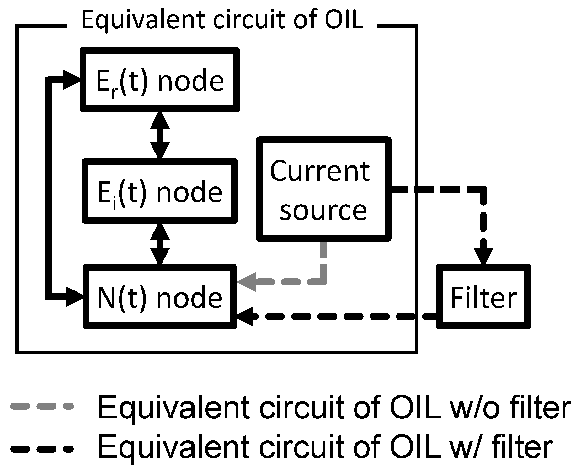
Although the rate equations based on photon number have been widely used in the optical simulation of lasers including OIL lasers [5], we modify the photon-based equations into electric field-based equation and rearrange the rate equations as (5)–(7). Electrical-field-based rate equations can be utilized, such as an optical phased array [23] and optical advanced modulation [24], which should consider optical interference. Moreover, we show that these field-based equations are suitable for the inclusion of optoelectronic device models in a SPICE-based electrical simulation framework [25,26]. Figure 2 shows the equivalent circuit of the OIL laser with E r ( t ) , E i ( t ) , and N ( t ) as nodes. Each node is connected by a dependent voltage source connector that is omitted in Figure 2.

3. Simulation Results

We first checked the validity of the OIL laser equivalent circuit in the SPICE simulator. We calculated the transient response of electrical field E ( t ) and phase ϕ ( t ) and compared them with the results calculated using an analytic derivation of the photon-based rate equations (Appendix A). For comparison, we define the phase ϕ ( t ) as the difference between the phase of the OIL laser and the master laser as follows:
ϕ ( t ) = ϕ O I L ( t ) ϕ i n j = tan 1 ( E i ( t ) E r ( t ) ) ,
where ϕ O I L ( t ) is the time-dependent phase of the OIL laser, and ϕ i n j is the phase of the master laser. We use the conversion relationship between the photon number S ( t ) and the electric field E ( t ) , which is defined as follows:
S ( t ) = E ( t ) · E * ( t ) = | E ( t ) | 2 = E r 2 ( t ) + E i 2 ( t ) .
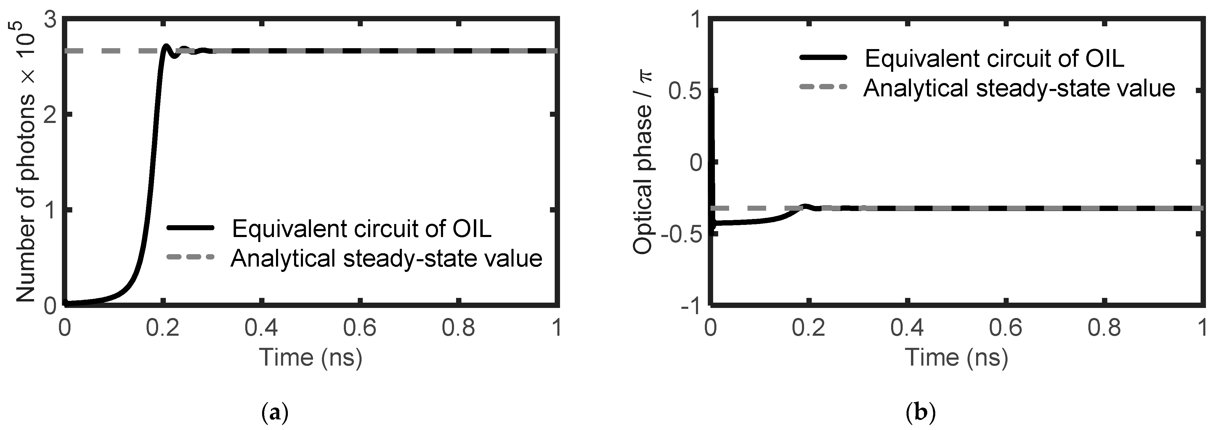
Figure 3a shows the transient responses of the photon numbers. The solid line indicates the results of the SPICE simulation based on our equivalent model in Figure 2. The dashed line is the steady-state value calculated by an analytic derivation of the photon-based rate equations. A similar confirmation was completed for phase ϕ ( t ) , as shown in Figure 3b. Both results confirm that the results of the SPICE model are consistent with those of the analytic derivation. The injection parameters were set to R = 10 × log ( S i n j / S f r ) = 0   ( dB ) and Δ ω i n j = 2 π × ( 50 × 10 9 ) ( rad / s ) . We chose these injection locking parameters because the injection ratio of 0 dB is easily achievable in real demonstration and the postion of the selected detuning freqeuncy is located around the middle of the stable locking map for the injection ratio, which ensures reliable locking operation of the OIL laser. The OIL laser is biased with a step change in the current from 0 to 5 × Jth at 0 s.

4. Modulation Performance Improvement

The modulation bandwidth, settling time of the relaxation oscillation, and damping ratio are important indicators that determine the modulation performance of a directly modulated laser [27]. Although the OIL laser exhibits a significant improvement in direct modulation performance over a free-running laser [10], the actual speed of the direct modulation pulse is limited to under a few hundred megahertz owing to the serious distortion in the output signal caused by the light intensity relaxation oscillation [28]. A highly damped resonance is required to eliminate the relaxation oscillation ringing for digital modulation. The settling time is the time when the error in the output is within 1–5% of the steady state. When the maximum modulation bit rate of the laser is shorter than the setting time of the relaxation oscillation, a bit-pattern effect occurs, and the laser modulation performance is degraded [29]. This limits the application of OIL lasers in practical applications. A high damping ratio and low settling time must be required for high-speed digital modulation [30]. To meet the requirements, we propose the preprocessing of a direct modulation signal for the OIL laser. Based on our equivalent circuit model, we can easily design an electrical preprocess circuit that compensates for the limitation in the direct modulation of the OIL laser. We propose to suppress the relaxation oscillation frequency by adding a filter in front of the laser circuit to reduce the relaxation oscillation.
Figure 4 shows the simulation results of the frequency responses of the free-running and OIL lasers. The relaxation oscillation frequency of a free-running laser is approximately 9.76 GHz and that of the OIL laser is approximately 23.255 GHz. Although the modulation bandwidth is more than doubled, a flat and broad 3-dB bandwidth is a more desirable characteristic for the optical source in various optoelectronic applications [31]. To meet this requirement, we designed a bandstop filter to suppress the relaxation oscillation during modulation and achieve a flat 3-dB bandwidth.
Figure 5 shows an equivalent circuit schematic with and without the filter. The equivalent circuit without the filter corresponds to Figure 2. The filter is inserted between nodes J b i a s ( t ) and N ( t ) in Figure 2.
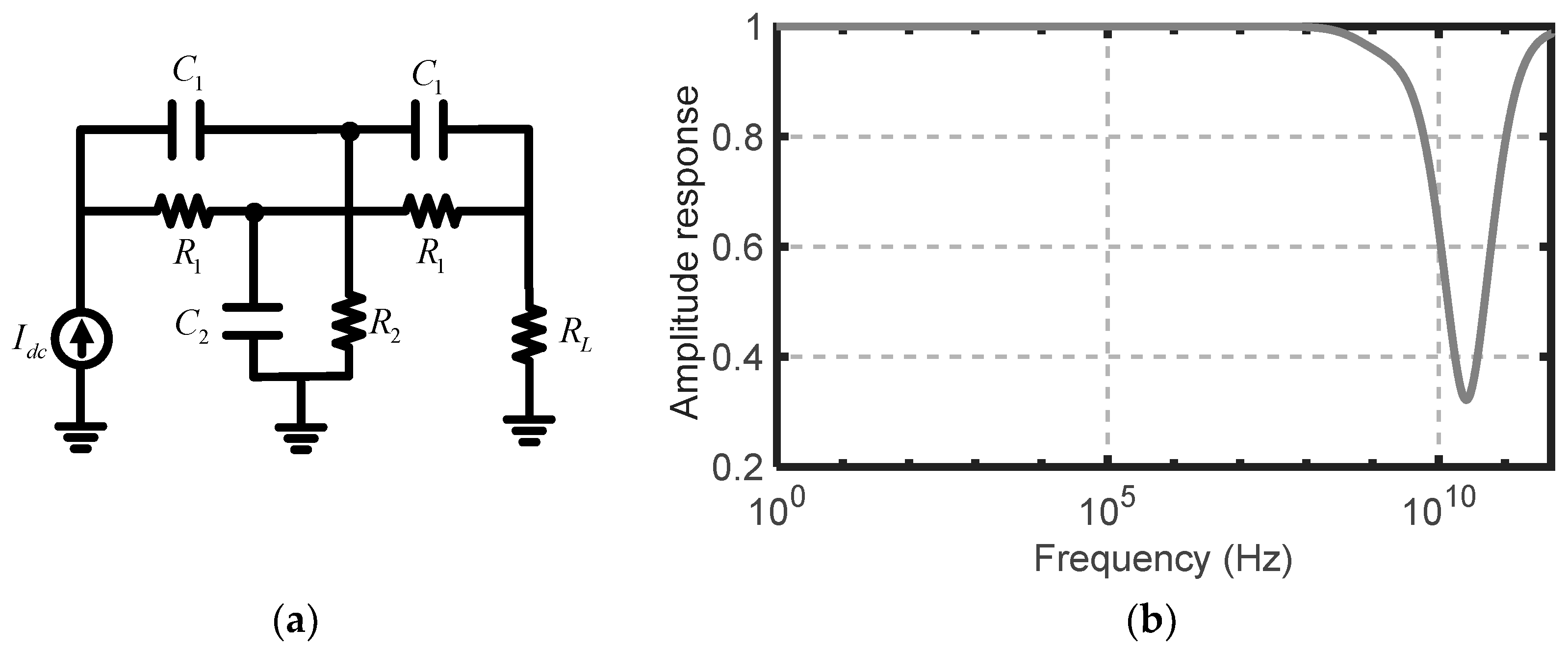
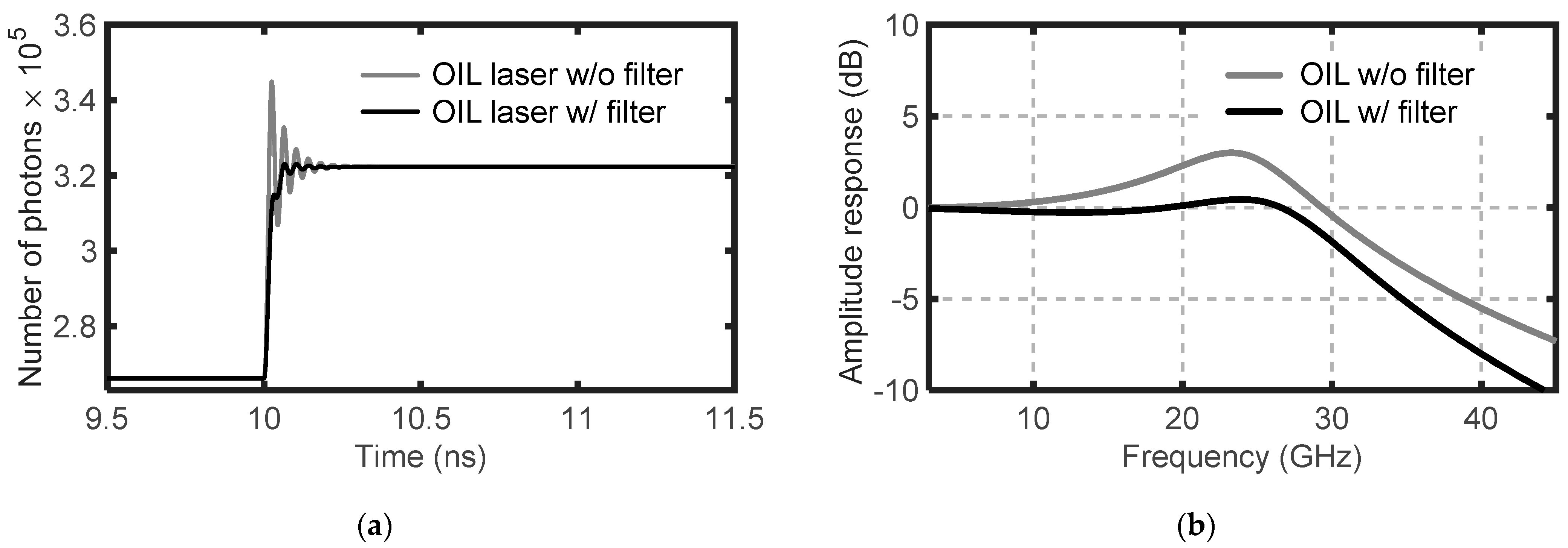
Figure 6a presents the schematic of the twin-T filter used as a bandstop filter to suppress the 25 GHz relaxation oscillation, and Figure 6b shows the frequency response of the bandstop filter. The bandstop filter with specific insertion loss and 3 dB bandwidth (or quality factor, Q-factor) should be designed and inserted in accordance with the frequency response of the OIL laser to minimize the effect of the unwanted strong relaxation oscillation. The frequency response of the OIL laser depends on the injection locking parameters [10]. Figure 7a shows the transient response of the OIL laser with and without the preprocessing of the direct modulation signal based on the bandstop filter. The input bias current is modulated from 5 × Jth to 6 × Jth at 10 ns. We focus on the elimination of the transient oscillation of the optical signal for the modulation current change from 5 × Jth to 6 × Jth in the simulation. The electrical filter should be carefully tuned or designed in accordance with such modulation parameters including the modulation depth, modulation speed, and modulation format. The equivalent circuit model reveals that the relaxation oscillation is significantly reduced by the application of the bandstop filter. The calculated damping ratio exhibits an increase of 0.101 (280%) from 0.056 to 0.157, and the settling time (1%) shows a decrease of 0.055 ns (44.6%) from 0.108 to 0.053 ns, respectively. Figure 7b shows the frequency response of the OIL laser with and without the preprocessing of the direct modulation signal based on the bandstop filter. It shows a wide and flat 3 dB bandwidth of 28.79 GHz as a result of the preprocessing of the direct modulation signal.

5. Conclusions

We derived an equivalent circuit model of an OIL laser to calculate its output using the SPICE simulator. We separate the real and imaginary parts of the rate equations to avoid numerical errors caused by the interference between signals and design the corresponding equivalent circuit. The modeled circuit was simulated using SPICE, and its reliability was verified by comparing its results with the analytical steady-state value. Subsequently, SPICE was used to design a preprocessing modulation circuit that improved the direct modulation performance of the OIL laser. Using our approach, we designed and applied a bandstop filter to suppress the relaxation frequency and enhance a flat 3 dB bandwidth. The equivalent circuit model of the OIL laser can be widely applied to evaluate its performance in various photonic and optoelectronic applications owing to its compatibility with circuit simulators.

Author Contributions

All authors contributed substantially to this article. The article was conceived and structured by all the authors. H.-K.S. and J.-H.C. conceived the simulation, analyzed the data, and wrote the paper. H.-J.B. performed the simulations and analyzed the data. All authors have read and agreed to the published version of the manuscript.

Funding

This work was supported by the National Research Foundation of Korea (NRF) under the Basic Science Research Program (NRF-2019R1I1A1A01058848 and 2021R1F1A104591911).

Conflicts of Interest

The authors declare no conflict of interest. The funders had no role in the design of the study; in the collection, analyses, or interpretation of data; in the writing of the manuscript; or in the decision to publish the results.

Appendix A

The following equation is the photon-based rate equation used for comparison with the transient response simulation results of the equivalent circuit model of the OIL laser [10]:
d S ( t ) d t = { g [ N ( t ) N t r ] γ P } S ( t ) + 2 κ S i n j S ( t ) cos [ ϕ ( t ) ϕ i n j ] ,
d ϕ ( t ) d t = α 2 { g [ N ( t ) N t r ] γ P } κ S i n j S ( t ) sin [ ϕ ( t ) ϕ i n j ] Δ ω i n j ,
d N ( t ) d t = J ( t ) γ N N ( t ) g [ N ( t ) N t r ] S ( t ) ,
where the time-dependent functions of, S ( t ) , ϕ ( t ) , and N ( t ) are the photon number, field phase, and carrier number, respectively, of the slave laser. In addition, ϕ ( t ) is the phase difference between the slave and master lasers: ϕ ( t ) ϕ s l a v e ( t ) ϕ m a s t e r ( t ) . Moreover, g , N t r , α , J , γ N , and γ P are the slave laser’s linear gain coefficient, transparency carrier number, linewidth enhancement factor, current, carrier recombination rate, and photon decay rate, respectively. The injection terms κ , S i n j , and Δ ω i n j are the coupling rate, injected photon number, and detuning frequency, respectively. The detuning frequency is formally defined as the difference between the master laser frequency ω M L and the free-running slave laser frequency ω f r : Δ ω ω M L ω f r .

References

  1. Baek, Y.S. Technical trends of photonic integrated circuits for high speed, high capacity optical communication. Electron. Telcom. Trend. 2009, 24, 52–60. [Google Scholar]
  2. Baek, Y.S. Optical components for high speed optical communications. Korean J. Opt. Photon. 2013, 24, 297–310. [Google Scholar] [CrossRef]
  3. Smit, M.; Williams, K.; van der Tol, J. Past, present, and future of InP-based photonic integration. APL Photonics 2019, 4, 050901. [Google Scholar] [CrossRef] [Green Version]
  4. Kim, J.J. Large-scale photonic integrated circuits. IEEE J. Sel. Top. Quantum Electron. 2006, 11, 1–14. [Google Scholar]
  5. Wang, J.; Haldar, M.K.; Mendis, F.V.C. Equivalent circuit model of injection-locked laser diodes. Microw. Opt. Technol. Lett. 1998, 18, 124–126. [Google Scholar] [CrossRef]
  6. Liu, Z.; Slavik, R. Optical injection locking: From principle to applications. J. Lightwave Technol. 2020, 38, 43–59. [Google Scholar] [CrossRef]
  7. Lau, E.; Sung, H.K.; Wu, M.C. Frequency response enhancement of optical injection-locked lasers. IEEE J. Quantum Electron. 2008, 44, 90–99. [Google Scholar] [CrossRef] [Green Version]
  8. Zhao, X.; Change-Hasnain, C.J.; Hofmann, W.; Amann, M.C. Modulation Efficiency Enhancement of 1.55-um Injection-Locked VCSELs. In Proceedings of the IEEE 20th International Semiconductor Laser Conference, Kohala Coast, HI, USA, 18–21 September 2006. [Google Scholar]
  9. Ramdane, A.C.; Gruning, P.; Roncin, V.; Du-Burck, F. Frequency stability transfer by optical injection locking into a semiconductor frequency comb. In Proceedings of the Joint Conference of the European Frequency and Time Forum and IEEE International Frequency Control Symposium, Besancon, France, 9–13 July 2017. [Google Scholar]
  10. Lau, E.K.; Wong, L.J.; Wu, M.C. Enhanced modulation characteristics of optical injection-locked lasers: A tutorial. IEEE J. Sel. Top. Quantum Electron. 2009, 15, 618–633. [Google Scholar] [CrossRef]
  11. Genest, J.; Chamberland, M.; Tremblay, P.; Tetu, M. Microwave signal generated by optical heterodyne between injection-locked semiconductor lasers. IEEE J. Quantum Electron. 1997, 33, 989–998. [Google Scholar] [CrossRef]
  12. Sung, H.K.; Lau, E.K.; Wu, M.C.; Tishinin, D.; Liou, K.Y.; Tasang, W.T. Large-Signal Analog Modulation response of Monolithic Opticcal Injection-Locked DFB Lasers. In Proceedings of the Conference on Laser and Electro-Optics, Baltimore, MD, USA, 22–27 May 2005. [Google Scholar]
  13. Perrott, A.H.; Caro, L.; Dernaika, M.; Peters, F.H. A Comparison between off and On-Chip Injection Locking in a Photonic Integrated Circuit. Photonics 2019, 6, 103. [Google Scholar] [CrossRef] [Green Version]
  14. Sorace, A.C.; Leu, J.; Watts, M.R.; Stojanovic, V. Electro-optical co-simulation for integrated CMOS photonic circuits with VerilogA. Opt. Express 2015, 23, 27180–27203. [Google Scholar] [CrossRef]
  15. Lim, D.W.; Cho, H.U.; Sung, H.K.; Yi, J.C. A PSPICE circuit modeling of strained AlGaInN laser diode based on the multilevel rate equations. J. Opt. Soc. Korea 2009, 13, 386–391. [Google Scholar] [CrossRef] [Green Version]
  16. Ganesh, M.M.; Rekha, E.; RajKumar, P. A comprehensive equivalnet circuit model for the study of thermal and spectral characteristics in laser diodes. Int. J. Lgts. Electron. Opt. 2013, 125, 3030–3036. [Google Scholar]
  17. Katz, J.; Margalit, S.; Harder, C.; Wilt, D.; Yariv, A. The intrinsic electrical equivalent circuit of a laser diode. IEEE J. Quantum Electron. 1981, 17, 4–9. [Google Scholar] [CrossRef]
  18. Smy, T.; Gunupudi, P. Robust simulation of opto-electronic systems by alternating complex envelope representations. IEEE Trans. Comput.-Aided Des. Integr. Circuits Syst. 2012, 31, 1139–1143. [Google Scholar] [CrossRef]
  19. Mogensen, F.; Olesen, H.; Jacobsen, G. Locking conditions and stability properties for a semiconductor laser with external light injection. IEEE J. Quantum Electron. 1985, 21, 784–793. [Google Scholar] [CrossRef]
  20. Henry, C.; Olsson, N.; Dutta, N. Locking range and stability of injection locked 1.54 µm InGaAsp semiconductor lasers. IEEE J. Quantum Electron. 1985, 21, 1152–1156. [Google Scholar] [CrossRef]
  21. Lang, R. Injection locking properties of a semiconductor laser. IEEE J. Quantum Electron. 1982, 18, 976–983. [Google Scholar] [CrossRef]
  22. Murakami, A.; Kawashima, K.; Atsuki, K. Cavity resonance shift and bandwidth enhancement in semiconductor lasers with strong light injection. IEEE J. Quantum Electron. 2003, 39, 1196–1204. [Google Scholar] [CrossRef]
  23. Nguyen, A.H.; Cho, J.H.; Bae, H.J.; Sung, H.K. Side-lobe level reduction of an optical phased array using amplitude and phase modulation of array elements based on optically injection-locked semiconductor lasers. Photonics 2020, 7, 20. [Google Scholar] [CrossRef] [Green Version]
  24. Liu, Z.; Kakande, J.; Kelly, B.; O’Carroll, J.; Phelan, R.; Richardson, D.J.; Slavik, R. Modulator-free quadrature amplitude modulation. Nat. Commun. 2014, 5, 5911. [Google Scholar] [CrossRef] [PubMed] [Green Version]
  25. Smy, T.; Klein, J.; Jakubczyk, J. Self-consistent simulation of opto-electronic circuits using a modified nodal analysis formulation. IEEE Trans. Adv. Packag. 2010, 33, 4. [Google Scholar]
  26. Quarles, T.; Newton, A.; Pederson, D.; Sangiovanni-Vinentelli, A. SPICE 3 Version 3F5 User’s Manual, 1st ed.; UC Berkely EECS: Berkeley, CA, USA, 1994. [Google Scholar]
  27. Safwat, W.Z.M.; Moustafa, F.A.; Kamal, A.; Alaa, M. Estimation of parameters controlling direct modulation of semiconductor lasers. In Proceedings of the 26th National Radio Science Conference, El-Minia, Egypt, 17–19 March 2009. [Google Scholar]
  28. Lang, R.; Kobayashi, K. Suppression of the relaxation oscillation in the modulated output of semiconductor lasers. IEEE J. Quantum Electron. 1976, 12, 194–199. [Google Scholar] [CrossRef]
  29. Ahmed, M.; Mahmoud, S.W.Z.; Mahmoud, A.A. Influence of pseudorandom bit format on the direct modulation performance of semiconductor lasers. Pramana 2012, 79, 1443–1456. [Google Scholar] [CrossRef]
  30. Yildirim, R.; Schetzen, M. Applications of the single-mode laser-diode system theory. Opt. Commun. 2003, 219, 351–355. [Google Scholar] [CrossRef]
  31. Rizk, T.; Mahmoud, A.; Abdel-Rahman, M.; Ahemd, M. Correlation of Small-Signal Modulation with Digital Modulation Characteristics of High-Speed Semiconductor Lasers. Phys. Wave Phenom 2020, 28, 49–54. [Google Scholar] [CrossRef]
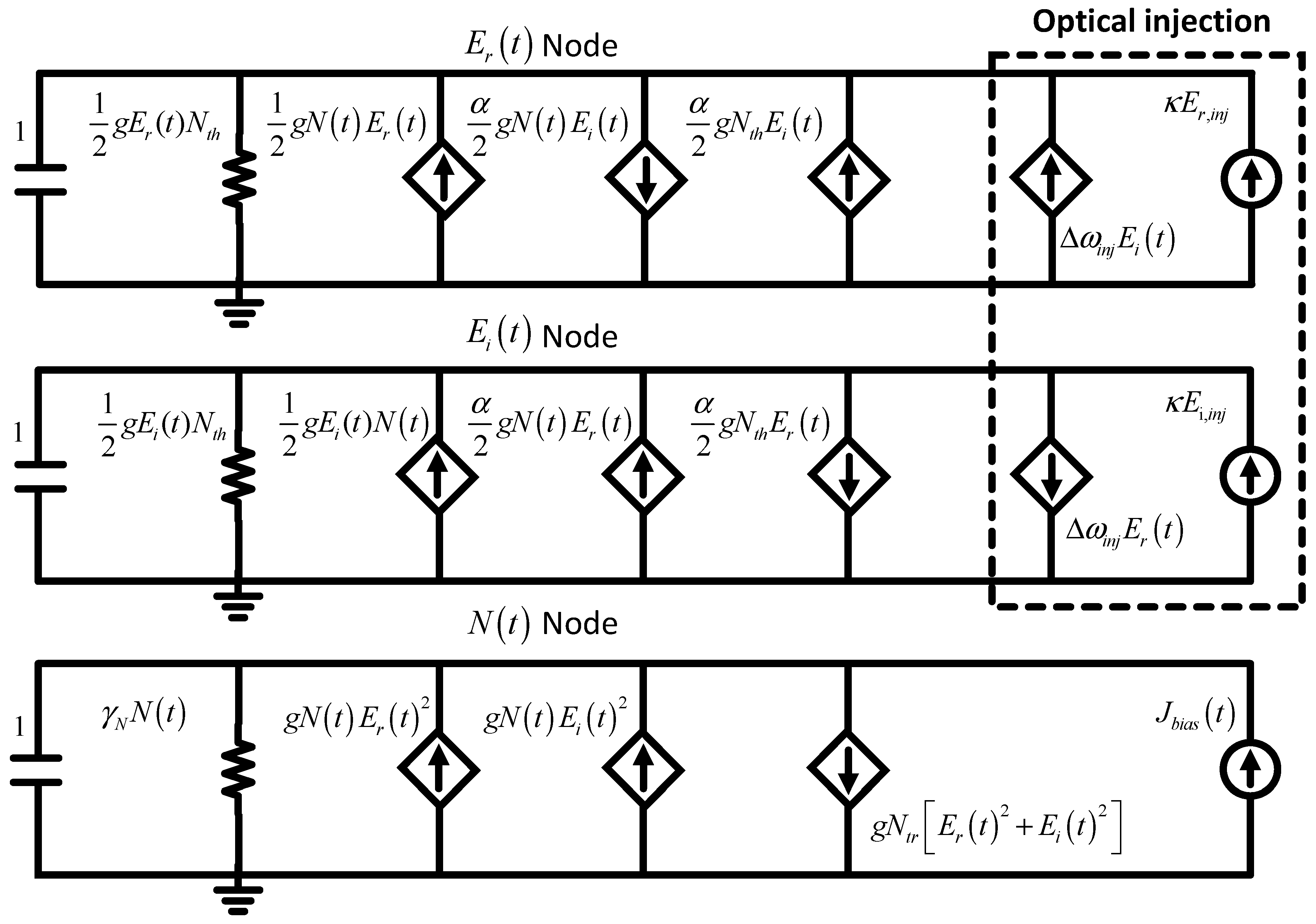
Figure 2. Equivalent circuit of an OIL laser, represented as the real and imaginary parts of the electric fields.
Electronics 10 02409 g002
Figure 3. (a) Number of photons S ( t ) of the OIL laser; (b) optical phase of the OIL laser. The solid lines are SPICE simulation results based on our equivalent circuit model and the dashed line represents steady-state values calculated by analytic derivation.
Electronics 10 02409 g003
Figure 4. Frequency responses of a free-running laser and OIL laser calculated by SPICE simulation based on the equivalent circuit model.
Electronics 10 02409 g004
Figure 5. Equivalent circuit schematic with or without preprocessing filter.
Electronics 10 02409 g005
Figure 6. (a) Bandstop filter circuit to suppress the relaxation oscillation of the OIL laser; (b) frequency response of the bandstop filter.
Electronics 10 02409 g006
Figure 7. (a) Transient response and (b) frequency response of the directly modulated OIL laser with and without preprocessing of direct modulation signal based on the bandstop filter.
Electronics 10 02409 g007
Table 1. Values used in the calculations.
SymbolQuantityValueUnit
λ0Wavelength1550nm
gNet stimulated gain4.7 × 1041/s
NtrTransparency carrier number9.36 × 106-
JthThreshold current2 × 10161/s
JbiasBias current5 × Jth1/s
γPPhoton decay rate5 × 10111/s
γNCarrier decay rate1091/s
αLinewidth enhancement factor5-
κCoupling ratio2251/s
Publisher’s Note: MDPI stays neutral with regard to jurisdictional claims in published maps and institutional affiliations.