1. Introduction
A global navigation satellite system (GNSS) is a positioning and time determination system that supports global navigation services using satellite constellations [
1]. The position and time information provided by GNSS is widely applied in the fields of national defense, finance, communications, and medicine, and its application has recently spread to various other fields such as autonomous driving and smart devices [
2,
3]. Representative GNSS satellite constellations include the U.S. Global Positioning System (GPS), Russia’s GLONASS, China’s BeiDou Navigation Satellite System (BDS), and the EU’s Galileo, and they have been continuously researched and developed with a view to improving the accuracy and use of satellite signals. GNSS signals are transmitted in the frequency bands determined by the satellites. For example, GPS signals, which are the most representative GNSS signals, consist of L1C/A and L1C signals in the L1 (1575.42 MHz) band, L2C signals in the L2 (1227.60 MHz) band, and L5 signals in the L5 (1176.45 MHz) band [
4].
To identify visible satellites among signals received from multiple satellites and to extract navigation messages, GNSS receivers use the pseudo random noise (PRN) code [
4]. The PRN code is characterized by having high correlation values for two same PRN codes, and low correlation values for two different PRNs codes. By using this characteristic of the PRN code, GNSS receivers can distinguish signals from different satellites. To maintain the correlation characteristic of the PRN code, it is important to carefully design the code. Note that since most GNSS satellite constellations employ CDMA, a different PRN is assigned to each satellite. Exceptionally, GLONASS L1OF and L2OF uses FDMA so that different satellites of GLONASS share the same PRN, and the satellites are distinguished using frequency difference.
Although conventional GNSS receivers have generally been designed for single signals, studies on multi-signal receiver design have recently been actively conducted to achieve high accuracy, precision, and reliability [
5,
6,
7]. In general, multi-signal receivers can be divided into multi-GNSS receivers that receive multiple GNSS signals of a single frequency band, multi-frequency receivers that receive single GNSS signals of multiple frequency bands, and multi-GNSS multi-frequency receivers that receive multiple GNSS signals of multiple frequency bands. However, in order for a multi-signal receiver to support various codes, the receiver should support the generation of individual codes. Therefore, the resulting problem of increased complexity must be solved. This paper proposes a structure for a universal code generator that can generate multiple codes by sharing hardware resources. With this foregoing structure, the optimized implementation of multi-signal receivers can be supported.
2. Background
The PRN code has high correlation values for the same PRN codes and low correlation values for different PRN codes. To generate a PRN code that has the correlation characteristic, there are three methods: a linear feedback shift register (LFSR), a Legendre sequence, and a memory code [
5]. The LFSR is a design method using linear combinations of shift registers, the Legendre sequence is a method based on a mathematical sequence, and the memory code is a method of storing and reading predetermined sequences in memory.
Table 1 shows the frequency bands and PRN code generation methods for representative GNSS signals. As shown in
Table 1, most of the signals are generated based on the LFSR, while the GPS L1C signals [
8] and the BDS B1C signals [
9] are generated using the Legendre sequence, and the code of the Galileo E1 signals [
10] is generated based on the memory code. This paper focuses on a structure that can support various signals by sharing hardware for LFSR, which is the most widely applied. As shown in
Figure 1, the LFSR-based code generator basically consists of shift registers, a Feedback Tap circuit, an Initial read-only memory (ROM), and an output circuit. The LFSR-based PRN generation method for GNSS is subdivided into M-sequence, gold code, and kasami code according to the detailed configuration of LFSR [
6].
2.1. M-Sequence
The M-sequence method that has a maximum length sequence (MLS) is a method of generating a sequence with the length of
, which is the maximum length that can be generated, through linear feedback using a shift register of length
N [
22,
23]. The PRN code of the M-sequence method has the property of having the highest correlation value at zero lag in the case of autocorrelation and almost no correlation value in the case of cross correlation. Signals that use the M-sequence code include GPS L2C [
11], GPS L5 I [
12], GPS L5 Q [
12], GLONASS L1OF [
13], and GLONASS L2OF signals [
13].
As shown in
Table 1, the code generator for GPS L2C signals is a representative example of M-sequence code generators [
11]. The codes of GPS L2C signals include the L2CM code and the L2CL code, and both codes use the same code generator structure.
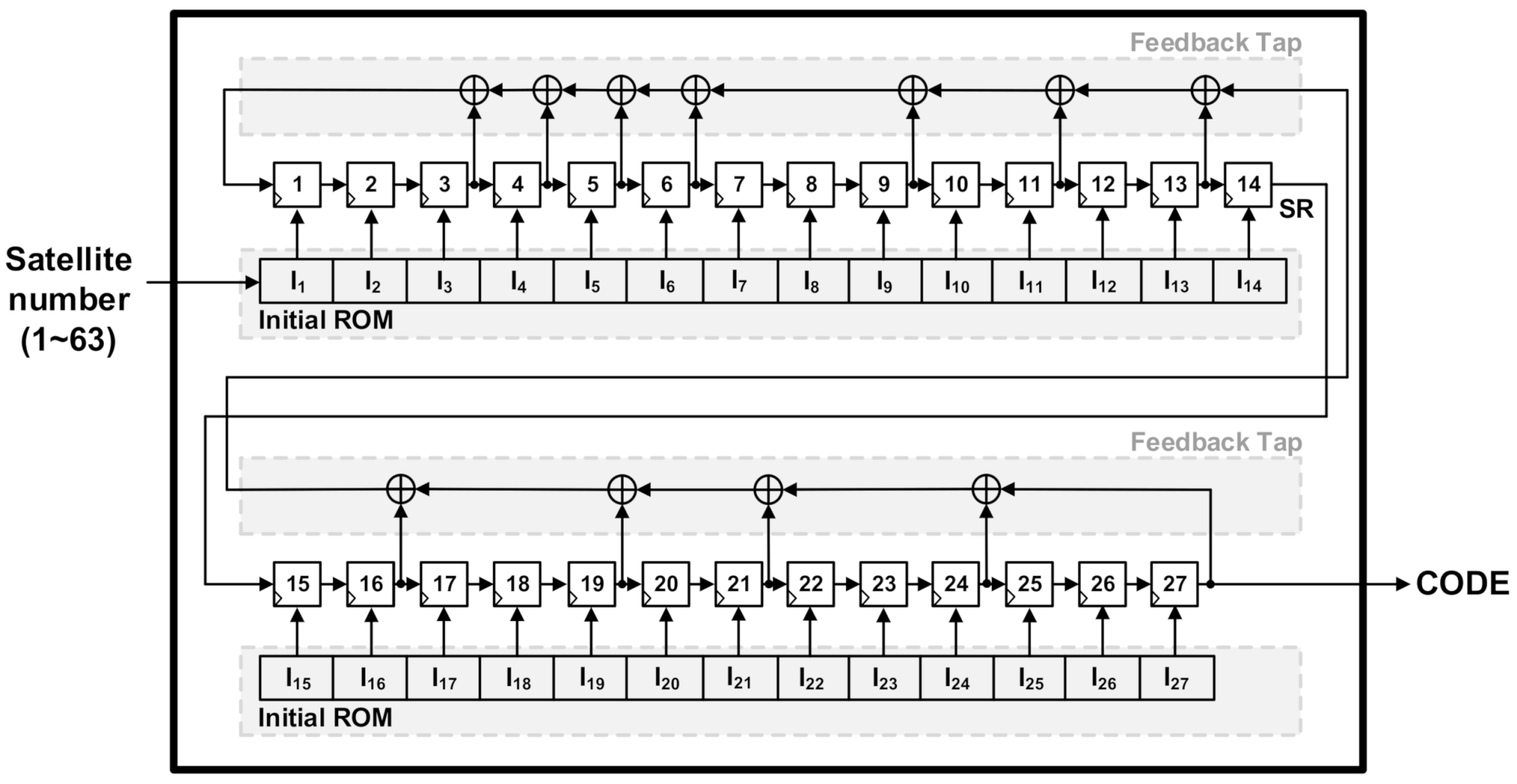
Figure 1 shows the architecture of the code generator for the GPS L2C signals converted into the Fibonacci LFSR. Please note that the code generator of GPS L2C signals has the structure of Galois LFSR in Interface Control Documents (ICD), but the structure can be converted into Fibonacci LFSR when it is used [
24]. The code generator shown in
Figure 1 consists of one 27-bit shift register, Feedback Tap, and Initial ROM. The feedback polynomial of the shift register is
. The initial value designated for each satellite number is stored in Initial ROM. When the satellite number is input into the Initial ROM, the stored initial value is input into the shift register and operates. After the initialized LFSR value is moved linearly, the value of the shift register is updated through the feedback circuit and operates. At this time, the last register output becomes the PRN code of the GPS L2C signal. The code generator shown in
Figure 1 can support both the L2CM code and L2CL code. The L2CM code generates PRN codes that are 10,230 chips long, and L2CL code generates PRN codes that are 767,250 chips long.
2.2. Gold Code
The gold code generator consists of two
N-bit shift registers with different feedback polynomials and initial values. The two
N-bit shift registers have two different M-sequences of equal length as outputs. Gold codes with lengths up to
are generated through the bitwise modulo sum of the two output sequences. Signals using gold codes include GPS L1C/A [
14], BDS B1I [
15], BDS B2I [
15], BDS B2A [
16], BDS B3I [
17], GLONASS L1OCd [
18], Galileo E5a [
19], and Galileo E5b [
19]. The two LFSR structures of the gold code generator are basically the same as the LFSR structure of the M-sequence generator structure shown in
Figure 1, but instead of storing the initial value of the shift register in the ROM, a phase selector circuit that selectively determines the output according to the satellite number may be added [
4]. Among the signals that use the gold code, the signals that use the phase selector are GPS L1C/A signals, BDS B1I and BDS B2I signals.
Figure 2 shows an example of a gold code generator that has the structure of a GPS L1C/A code generator [
14]. The gold code generator shown in
Figure 2 consists of 10-bit shift registers SR1 and SR2, Feedback Taps1/2, Initial ROMs 1/2, and a phase selector. The feedback polynomial of SR1 is
, and the feedback polynomial of SR2 is
. Each polynomial is implemented with Feedback Taps 1/2. The initial value information of the two shift registers is stored in Initial ROMs 1/2, and the stored initial values are set in shift registers SR1 and SR2. Furthermore, the phase selector selects the two register outputs determined for each satellite number from shift register SR2 to perform modulo-2 summing. In detail, the phase selector consists of as many multiplexers (MUXs) as shift registers, a Selection ROM that stores the multiplexers’ control signals, and exclusive OR (XOR) logic. When a satellite number is input, two register outputs determined for each satellite number are selected due to the control signal information stored in the Selection ROM, and modulo-2 summing can be performed. Finally, the L1C/A code is generated with the last register output of shift register. SR1 and the modulo-2 sum of the output of the phase selector and has a length of 1023 chips.
2.3. Kasami Code
When compared with the gold code generator shown in
Figure 2, the kasami code generator is identical in that it consists of two LFSRs but is different in that the length of the LFSR is different. In detail, the shift register of the kasami code generator uses an
N-bit shift register and a half-length
N/2-bit shift register to generate the kasami code, which is
long at maximum. Signals that use the code type of the kasami code include GLONASS L1OCp [
18], GLONASS L2OC [
20] and GLONASS L3OC [
21].
Figure 3 shows the GLONASS L2OC code generator, which is an example of a kasami code generator. The generator consists of a 14-bit shift register SR1, a 7-bit shift register SR2, Feedback Taps1/2, and Initial ROMs1/2 [
20]. The feedback polynomial of SR1 shown in
Figure 3 is
, and the feedback polynomial of SR2 is
. The initial value of SR1 and the initial value of SR2 are stored in Initial ROMs1/2, respectively, and in this case, the initial value of SR2 has different initial values by satellite number. When the predetermined feedback polynomial and initial value are set and operate, the outputs of the 14th register of shift register SR1 and the 7th register of shift register SR2 are modulo-2 summed to generate 10,230 chips long L2OCp code of GLONASS L2OC.
3. Previous Multi-Frequency Universal Code Generator
The characteristics of the LFSR-based code generator for generating the PRN code are determined by the length of the shift registers, the feedback polynomials, the initial values, and the output registers. The various types of LFSR-based code generators shown in
Table 1 have their own values, which are described in their respective ICDs. A code generator structure that supports various codes is an essential element in the development of multi-signal receivers, which have been recently studied to improve accuracy, precision, and reliability. In addition, since the complexity of the code generator increases linearly by the number of supported codes, an efficient receiver structure must be studied without fail. Recently, [
6] proposed an LFSR structure that can support multiple codes. The hardware was configured to share the shift register of the LFSR and to selectively determine different feedback polynomials, output registers, and initial values by code generator. Through the foregoing, multiple codes can be selectively generated with a single LFSR hardware device.
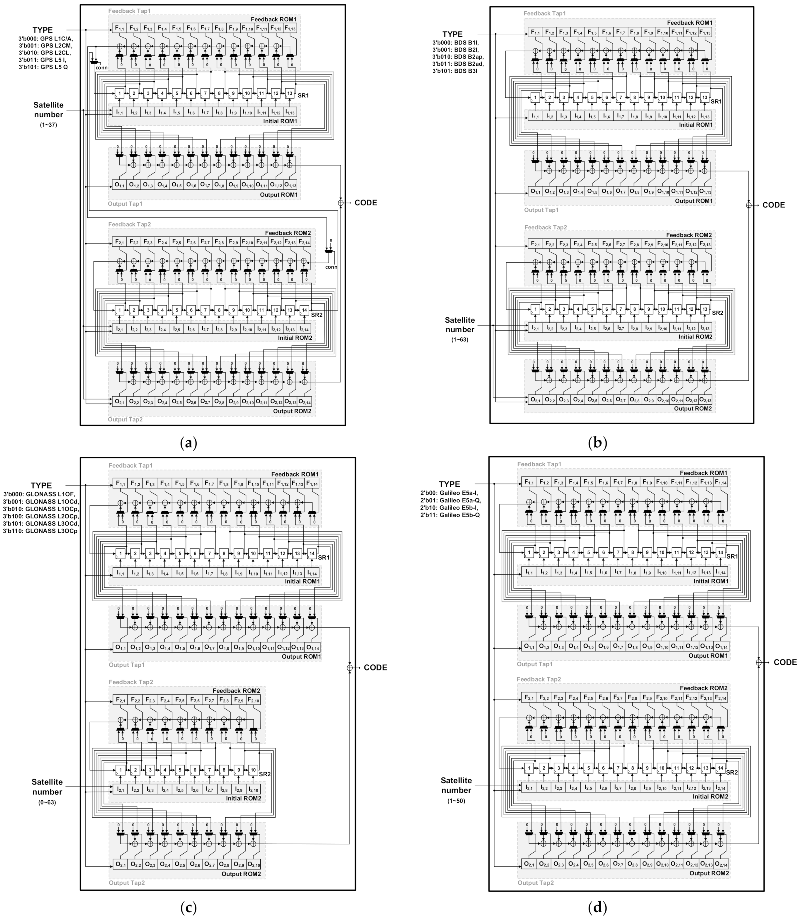
Figure 4 shows the hardware architectures of the previous multi-frequency universal code generators for signals using the LFSR-based code generators by GNSS.
Figure 4 shows the hardware architectures of the previous LFSR-based multi-frequency universal code generators that can generate the codes of GPS signals, BDS signals, GLONASS signals, and Galileo signals, respectively. The previous multi-frequency universal code generators shown in
Figure 4 commonly consist of shift registers SR1 and SR2, Feedback Taps1/2, which set the feedback polynomial of each shift register, Initial ROMs1/2 that store the initial values of the two shift registers, and Output Taps1/2, which determine the output registers.
The length of the shift register of previous multi-frequency universal code generators is determined by the length of the longest shift register among the shift registers of the code generators by signal. As shown in
Table 1, the previous multi-frequency universal code generator for GPS signals shown in
Figure 4a supports GPS L1C/A, GPS L2CM, GPS L2CL, GPS L5 I, and GPS L5 Q. Since the M-sequence-based code generator for GPS L2C signals requires the 27-bit shift register and the gold code-based code generator for GPS L5 signals requires the 13-bit, 13-bit shift registers, the two shift registers SR1 and SR2 were designed to be 13 bits and 14 bits, respectively. The control signal conn selectively determines the operations of M-sequence-based L2C signals and gold code-based L1C/A and L5 signals. As with the universal code generator for GPS signals, in the case of the previous multi-frequency universal code generator for BDS signals shown in
Figure 4b, the BDS B2A and B3I signals, which use the maximum number of bit shift registers in the code generator, use 13-bit, 13-bit shift registers. Therefore, both SR1 and SR2 were designed to be 13 bits. In the case of the previous multi-frequency universal code generators for GLONASS signals shown in
Figure 4c, since the GLONASS L2OC and L3OC signal code generators use 14-bit and 7-bit shift registers, respectively, and both code generators use 10-bit shift registers to generate the L1OCd code of the GLONASS L1OC signals, SR1 and SR2 are 14 bits and 10 bits, respectively, which are the maximum numbers of bits. Finally, in the case of the previous multi-frequency universal code generators for Galileo signals shown in
Figure 4d, since the code generators for all signals use 14-bit, 14-bit shift registers, SR1 and SR2 are 14 bits and 14 bits.
As shown in
Figure 4, in [
6], the maximum length shift register was implemented, and ROM, MUX, and XOR circuits were configured so that feedback polynomials, output registers, and initial values different by code generator can be selectively determined. As many multiplexers as the number of bits of the shift register, as many XOR logics as (the number of bits of the shift register − 1), and Feedback ROMs1/2 and Output ROMs1/2 that store the multiplexers’ control signals are used. Initial ROMs1/2 store the initial values determined by code, and the initial values are set in the shift registers connected according to the code types and satellite numbers. Therefore, each ROM needs as much width as the number of shift registers and as much depth as the supported (code types × the number of satellite numbers).
The code generators shown in
Figure 4 can universally generate various types of codes with a single LFSR structure. The code type and the satellite number are received as inputs, the feedback polynomials, output registers and initial values of SR1 and SR2 are determined, and the generated PRN codes are output as codes. For example, in the case where the PRN code for satellite number 2 of the GPS L1C/A signals is generated using the code generators shown in
Figure 4a, in order to set the feedback polynomials, Feedback Taps 1/2 receive the code type as an input, and
is set to {0001000000100}, and
is set to {00001110100110}. In addition, to set the output registers, Output Tap1 receives the code type and
is set to {0001000000000}. Since Output Tap2 is affected by the satellite number, it receives code type and satellite number as inputs, and
is set to {00000001000100}. Additionally, since Initial ROMs1/2 are affected by the satellite number, they receive the code type and satellite number as inputs, and
is set to {0001111111111}, and
is set to {00001111111111}. Therefore, the universal code generator structure presented in [
6] can reduce hardware complexity because it can selectively generate various codes according to the given type and satellite number inputs.
4. Proposed Multi-Frequency Universal Code Generator
Although the previous universal code generators can generate various codes using a single LFSR, there are many unnecessary elements in the values stored by supported satellite signal. The proposed multi-frequency universal code generator is intended to remove the unnecessary elements to further reduce the complexity.
Whereas the previous universal code generator configured Initial ROMs, Feedback ROMs, and Output ROMs for all register bits so that they can operate selectively, the proposed universal code generator opened the bits that are not regularly used and directly connected the bits that are used regularly to remove unnecessary ROM, MUX, and XOR circuits. By applying the hardwiring technique, redundant hardware resources can be significantly reduced compared to previous multi-frequency universal code generators.
Table 2,
Table 3,
Table 4 and
Table 5 show summaries of the ROM values of the conventional code generators in binary numbers by GNSS signal. Commonly unused bits were expressed as 0, used bits as 1, and non-fixed bits as don’t care X. According to the summaries, many bits are fixed to 0 and 1, so that a large number of hardware resources can be reduced by applying the hardwiring technique. Although the don’t care X bits require ROM, MUX, and XOR identically to the existing hardware configuration, the shift registers corresponding to bit 0 can be configured by removing the ROM, MUX, and XOR and opening them. In the case of the shift registers corresponding to bit 1, the ROM and MUX can be removed and an XOR connection can be directly configured. Therefore, the more the fixed bits 0 and 1 exist, the more the unnecessary hardware resources can be removed.
Figure 5 shows the hardware architectures of the proposed multi-frequency universal code generator by GNSS.
Figure 5 shows universal code generators that can generate GPS signals, BDS signals, GLONASS signals, and Galileo signals, respectively. On reviewing
Figure 5, it can be seen that the use of multiplexers and XOR logic was reduced compared to
Figure 4 by applying the hardwiring technique. As multiplexer use is reduced, the use of ROMs used for the Feedback ROMs1/2, which store the multiplexer control signals of Feedback Taps1/2, and the Output ROMs 1/2, which store the multiplexer control signals of the Output Taps1/2, can also be reduced. Additionally, in the case of GLONASS, Galileo and BDS, the hardwiring technique can also be applied to Initial ROM. Since the ROM use is reduced by 1 depth per 1 bit width for the bit widths applied by the hardwiring technique, a large amount of ROM use can be reduced in cases where satellite numbers are received as inputs. Therefore, in order to check the reduction rate of unnecessary hardware resources, the normalized multiplexer use, normalized XOR logic use, and normalized ROM use for each of the GNSS shown in
Figure 4 and
Figure 5 are shown in
Table 6.
Figure 5a shows the proposed multi-frequency universal code generator for GPS signals, indicating that the use of multiplexers, XOR logics, and ROMs decreased by 43%, 39%, and 4%, respectively, compared to
Figure 4a.
Figure 5b shows the proposed multi-frequency universal code generator for BDS signals, indicating that the use of multiplexers, XOR logics, and ROMs decreased by 29%, 29%, and 5%, respectively, compared to
Figure 4b.
Figure 5c shows the proposed multi-frequency universal code generator for GLONASS signals, indicating that the use of multiplexers, XOR logics, and ROMs decreased by 54%, 59%, and 5%, respectively, compared to
Figure 4c.
Figure 5d shows the proposed multi-frequency universal code generator for Galileo signals, indicating that the use of multiplexers, XOR logics, and ROMs decreased by 73%, 69%, and 7%, respectively, compared to
Figure 4d.
5. Experimental Results
In the experiment, synthesis and implementation were carried out with Xilinx Vivado 2020.2, and the Kintex Ultrascale KCU105 board was used as the field programmable gate array (FPGA) board. Conventional code generators by GNSS and a previous multi-frequency universal code generator were implemented for comparison with the proposed code generator. All codes generated from conventional, previous, and proposed were the same as the as the code provided from official ICD, implying that all the codes can be used for acquisition and tracking in a GNSS receiver. With the results of the synthesis, the look up tables (LUTs) and registers of the existing code generator and the proposed code generator were compared.
Figure 6 shows a comparison of the normalized hardware resource use of the proposed multi-frequency universal code generator, the previous universal code generator, and the conventional code generators by GNSS, and it can be seen that the hardware complexity was significantly reduced in the proposed multi-frequency universal code generator. As shown in
Figure 6a, the LUT use of the proposed multi-frequency universal code generator for GPS signals is reduced by about 13% compared to the previous universal code generator and about 10% compared to the sum of the hardware resource use of the conventional code generators. In addition, since the previous universal code generator and the proposed multi-frequency universal code generator share the shift registers needed to generate the codes, the resistor use is reduced by about 71%. When comparing the hardware resource utilization for BDS, GLONASS, and Galileo signals, it can be seen that in the case of BDS signals, as shown in
Figure 6b, the proposed multi-frequency universal code generator reduced LUT utilization by about 11% compared to that of the previous multi-frequency universal code generator and reduced LUT utilization by about 23% and the register utilization by about 78% compared to the sum of the hardware resource utilization of the conventional code generators. In the case of GLONASS signals, as shown in
Figure 6c, the proposed multi-frequency universal code generator reduces LUT utilization by about 18% compared to the previous multi-frequency universal code generator and reduces LUT utilization by about 17% and the resistor utilization by about 78% compared to the sum of the hardware resource utilization of the conventional code generators. In particular, in the case of Galileo signals, since the hardwiring technique can be applied to all of Output Tap1, Output Tap2, and Initial ROM1 as shown in
Table 5, the proposed multi-frequency universal code generator could save a lot of hardware resources. As shown in
Figure 6d, the proposed multi-frequency universal code generator reduced LUT utilization by about 36% compared to that of the previous multi-frequency universal code generator and reduced LUT utilization by about 37% and the register utilization by about 74% compared to the sum of the hardware resource utilization of the conventional code generators. In conclusion, the proposed universal LFSR structure can generate various codes with single hardware that always requires lower hardware resources than existing studies by applying the hardwiring technique.


