Abstract
The analysis presented in this paper is focused on the harmonics distortion damping in the case of bidirectional power-flow of the electronics device—matrix converter as an interface between two power sources. Bidirectional energy flow takes place in the matrix converter that is used in renewables, hybrid transformers, microgrids, etc. It is observed that the matrix converter generates sinusoidal voltage with some amount of harmonic distortion and worsens in the quality of power in the utility grid. Taking into account the bi-directional energy flow and the matrix converter operation principle, four key requirements for the filters are formulated. Six theoretically possible filter topologies are investigated for compliance with these requirements. Two of the filter topologies are recognized as complying with these requirements and applicable for the switching ripple harmonics damping in the utility grid connected matrix converter in the case of bidirectional power flow. The suitability of these topologies was verified by MATLAB/Simulink simulation. Using the proper filter topology will significantly reduce the size, weight and cost of the components of the filter, as well as the utility grid’s pollution by switching ripple harmonics. It is appropriate to apply such filters to matrix converters that operate in wind turbines installed in doubly fed induction generators. These filters should also be used in hybrid transformers and other high-power devices with matrix converters.
1. Introduction
Nowadays, with the high development of renewable energy sources, more and more power systems are characterized by large shares of resources interfaced with power electronics [1]. Wind energy generation has shown, and will continue to show, its vital presence in the upcoming years. Presently, the technology is moving towards variable speed wind energy conversion systems (WECS). Wind turbines equipped with doubly-fed induction generators (DFIG), which belong to variable speed WECS, have already proven their superiority over other configurations. DFIGs have many benefits and their competitive advantages make them the favorite choice for wind energy conversion systems that can be connected to power grids. The main advantage of the doubly-fed scheme over the singly-fed scheme is that the power converter required for the control of the machine can have a substantially reduced volt-ampere rating. Unlike other grid-connected renewable energy plants, the converter in the DFIG-based WECS provides bidirectional power-flow control, thereby enabling the DFIG to operate in either sub-synchronous or super-synchronous modes.
The use of power electronics technology in AC transmission systems is one of the pillars of the implementation of the flexible microgrid [2]. A hybrid distribution transformer is a potential cost effective solution to microgrid control devices. The hybrid distribution transformer is realized by augmenting a regular transformer with a fractionally rated power electronic converter, which provides the transformer with additional control capabilities. The hybrid distribution transformer can provide dynamic AC voltage regulation, phase angle control harmonic compensation and voltage sag compensation.
Currently, most of the wind power plants, hybrid transformers and microgrids are equipped with a two-stage back-to-back converter with DC link, which allows bidirectional power flow and converts the variable frequency voltage to the power grid frequency 50/60 Hz voltage [3]. However, in the DC link, large electrolytic capacitors are used, which are components with the shortest lifetime in comparison with any semiconductor element used in these converters. Furthermore, the presence of the electrolytic capacitor limits high temperature applications of the converter. The electrolytic capacitors also increase maintenance costs of the power system components. Using converters without the DC link would reduce the maintenance costs, size, increase reliability and the operating life of the converters, as well as the whole renewable energy sources based power system.
In this paper, an application of the one-stage matrix converter (MC) is studied, since it provides some advantages such as:
- inherently bidirectional power flow—the one-stage MC can deliver or take power from the utility grid via direct conversion between input and output of the converter;
- the control modules of the MC are simpler than those needed by the two-stage power converters as both input current and output target voltages are modulated within the same algorithm;
- absence of limited operation time capacitors;
- distribution of the thermal stress in the commutation elements because of the high number of switches;
- higher maximum power density;
- higher maximum power to mass ratio.
The MC is capable of providing sinusoidal output voltages with varying amplitude and frequency, and sinusoidal input currents with adjustable power factor, irrespective of the load [4].
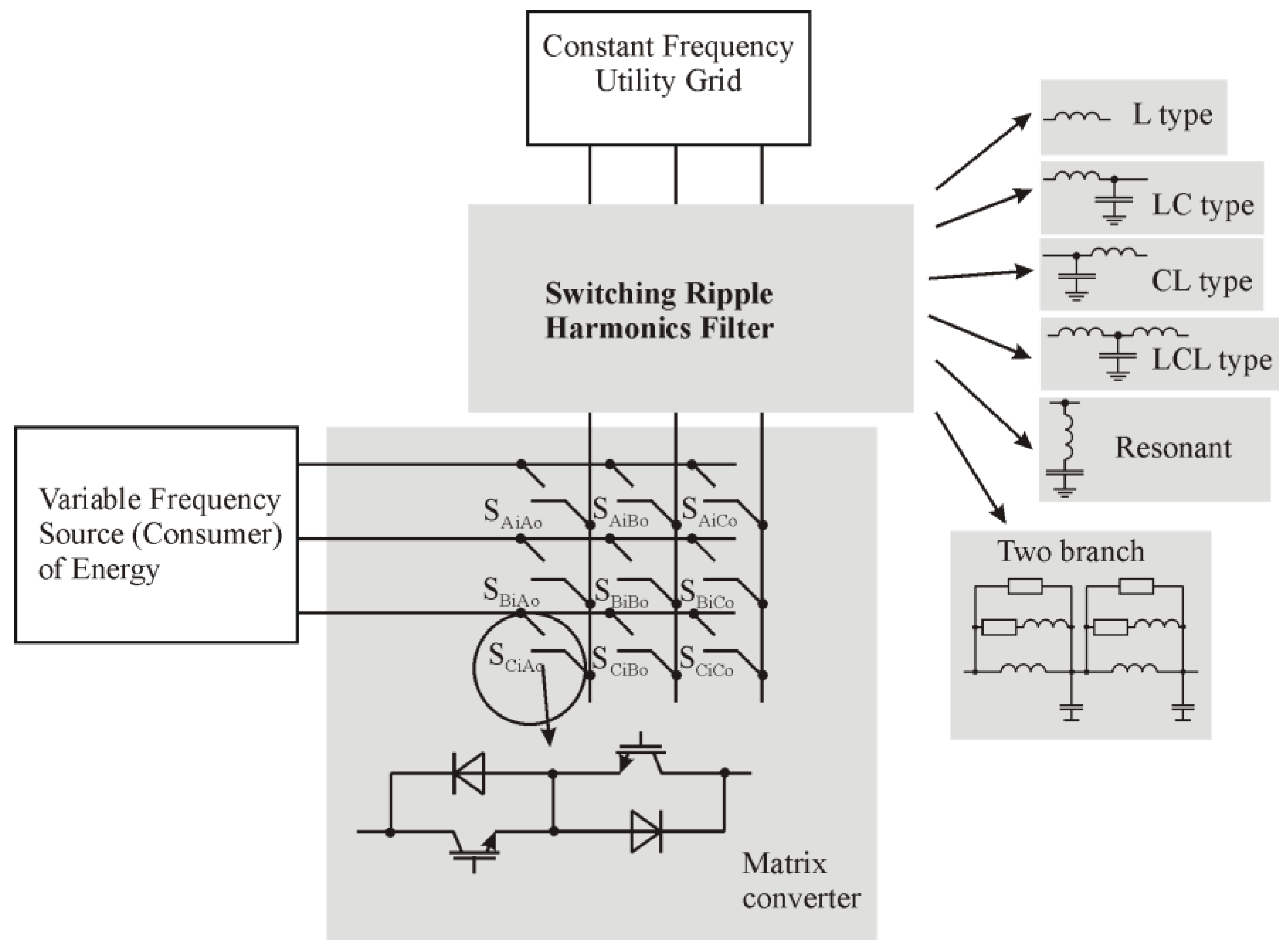
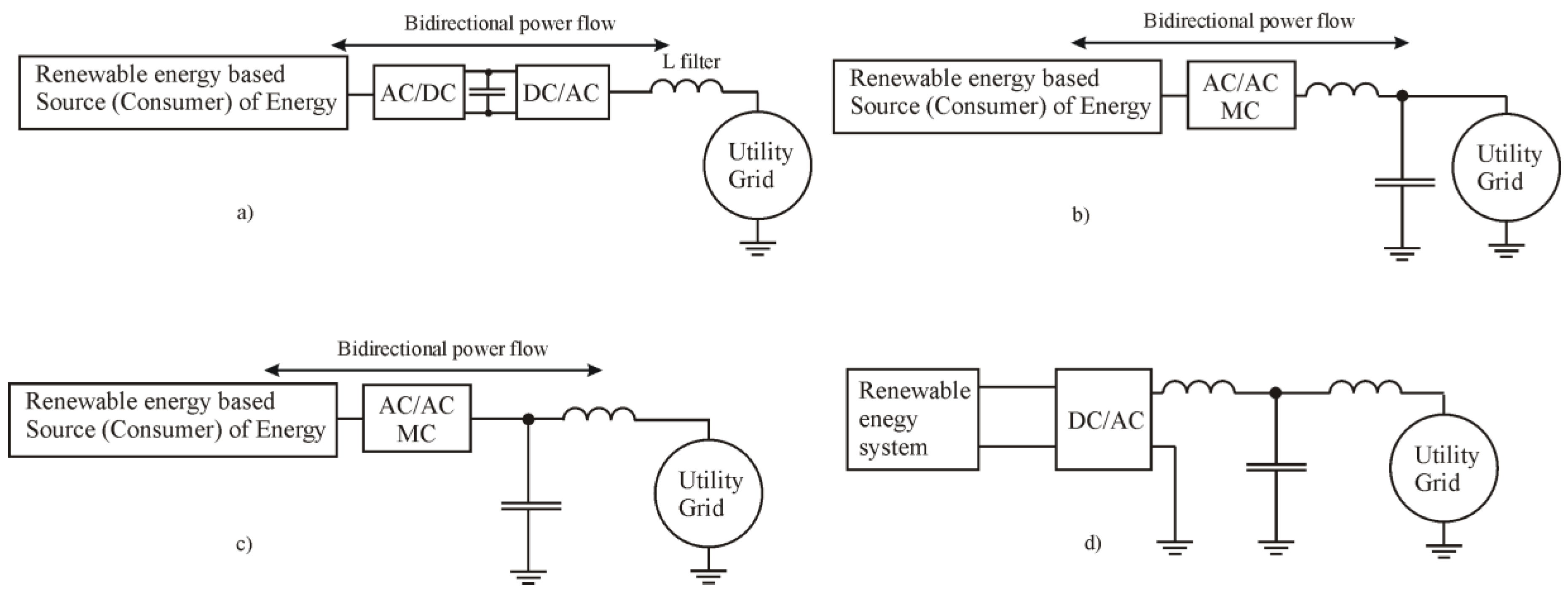
The MC is composed of nine semiconductor-based bidirectional switches. As presented in Figure 1, the MC could be used as an intermediate circuit between variable frequency source (consumer) of energy and constant frequency utility grid. Unlike other grid connected renewable energy plants, the matrix converter in the DFIG-based wind energy conversion systems provides bidirectional power-flow control, thereby enabling the DFIG to operate in either sub-synchronous or super-synchronous modes.
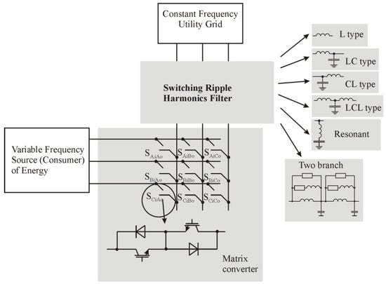
Figure 1.
The diagram of the system researched in this paper.
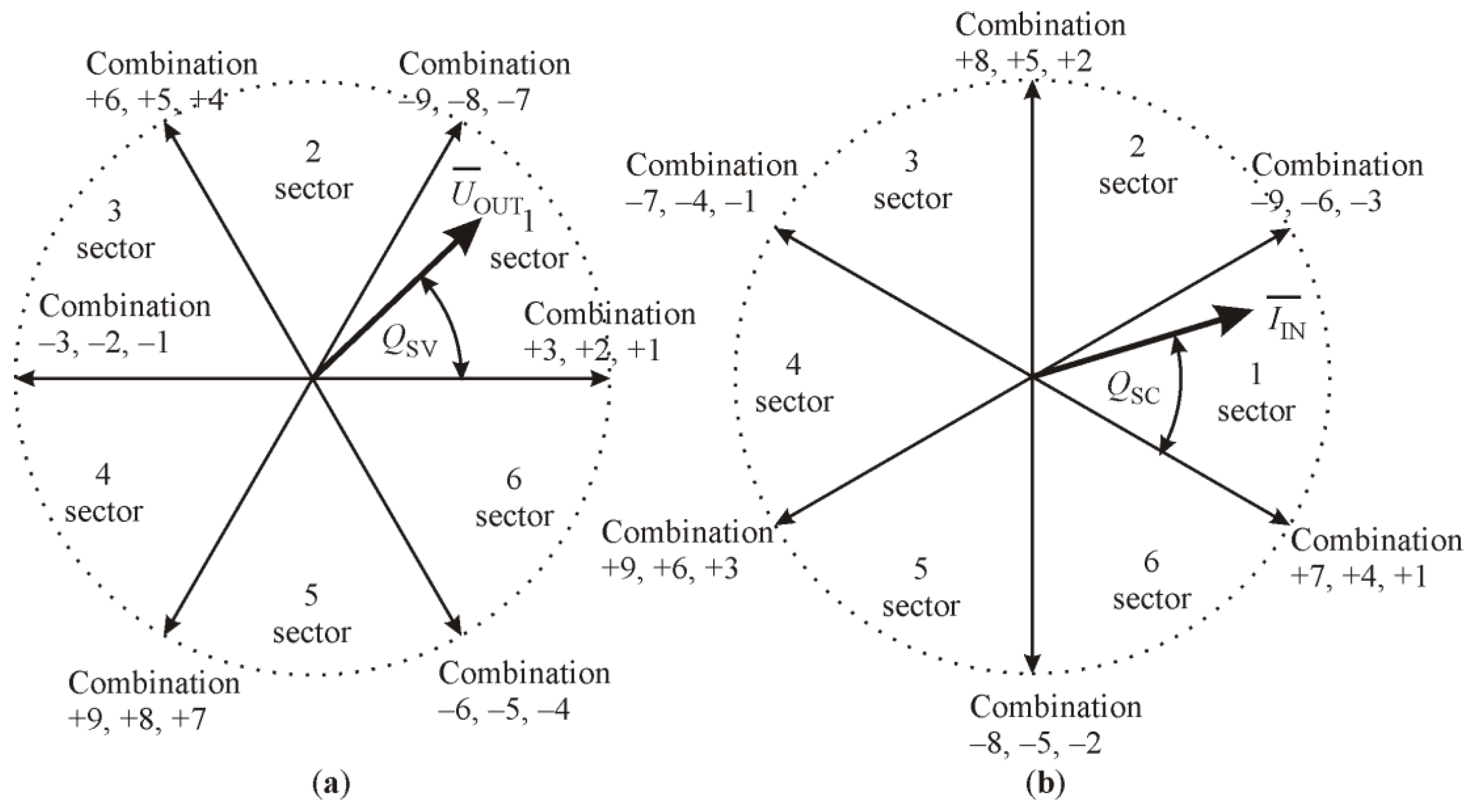
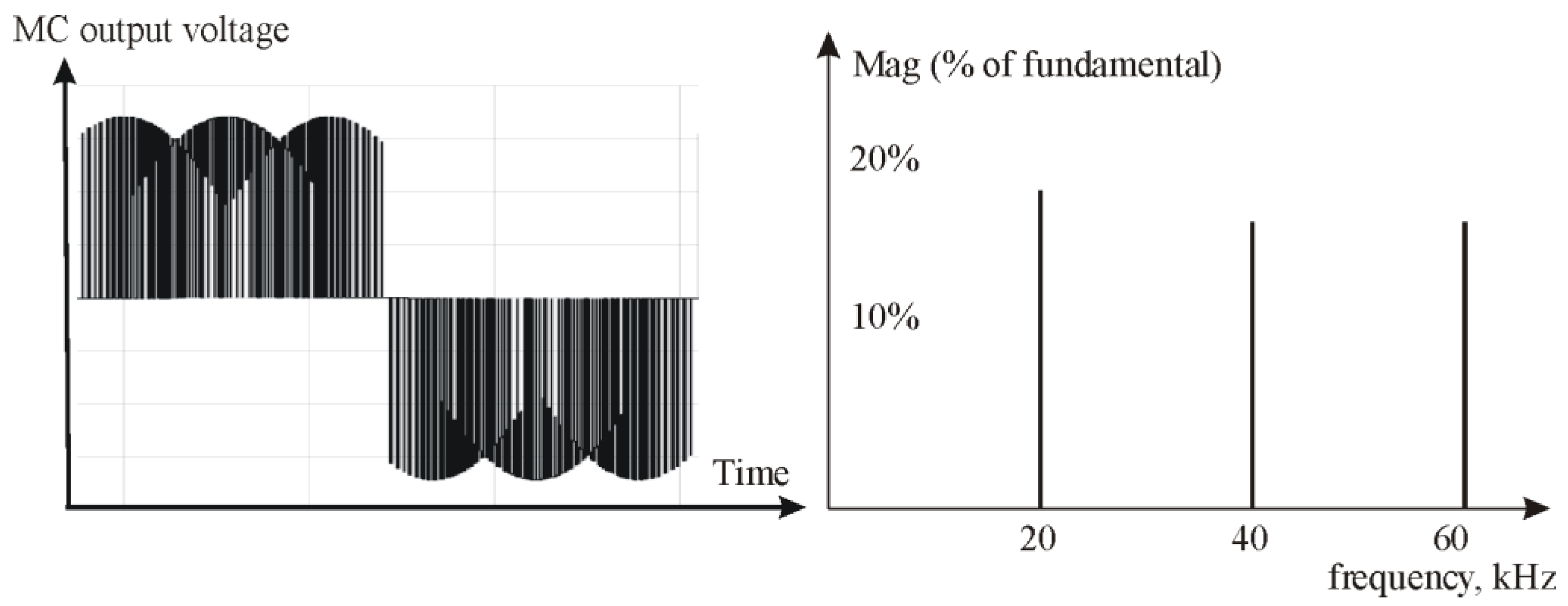
The MC is a forced commutated converter that consists of nine bidirectional switches as the power elements to create a variable output voltage system. In contrast to the back-to-back converter, the MC contains no large energy storage elements (capacitors). The key element of the MC is the fully controlled four-quadrant bidirectional switch, which allows high-frequency operation. As presented in Figure 1, there are 27 possible combinations (vectors) for the bidirectional switches of this three-to-three phase matrix converter. With an MC, indirect space vector modulation (ISVM) can be applied to control output voltage and input current. The ISVM considers the MC to be of the indirect form of converter. It features a virtual voltage source inverter (VSI) control part, a current source rectifier (CSR) control part and a DC link in between. By using the ISVM strategy, the desired output voltage and input current are synthesized from the active vectors and zero vectors. As shown in Figure 2, the active vectors are formed from 18 possible switch combinations (−9, −8, …, +8, +9) [5].
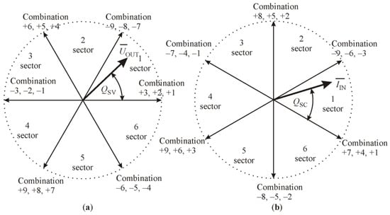
Figure 2.
Graphic interpretation of bidirectional switch combinations: (a) sectors and direction of the output voltage vectors; (b) sectors and directions of the input line current vectors.
The two adjacent vectors approximate the space vector of the desired output line voltages and input currents. As presented in Equations (1) and (2), the frequency of the MC output voltage is determined by the angle QSC, and the input current displacement is determined by the angle QSV.
where t is the time, determined through synchronization with the frequency of the power distribution lines, and φin is the preferred current displacement angle, which determines the reactive power at the area of input of the MC.
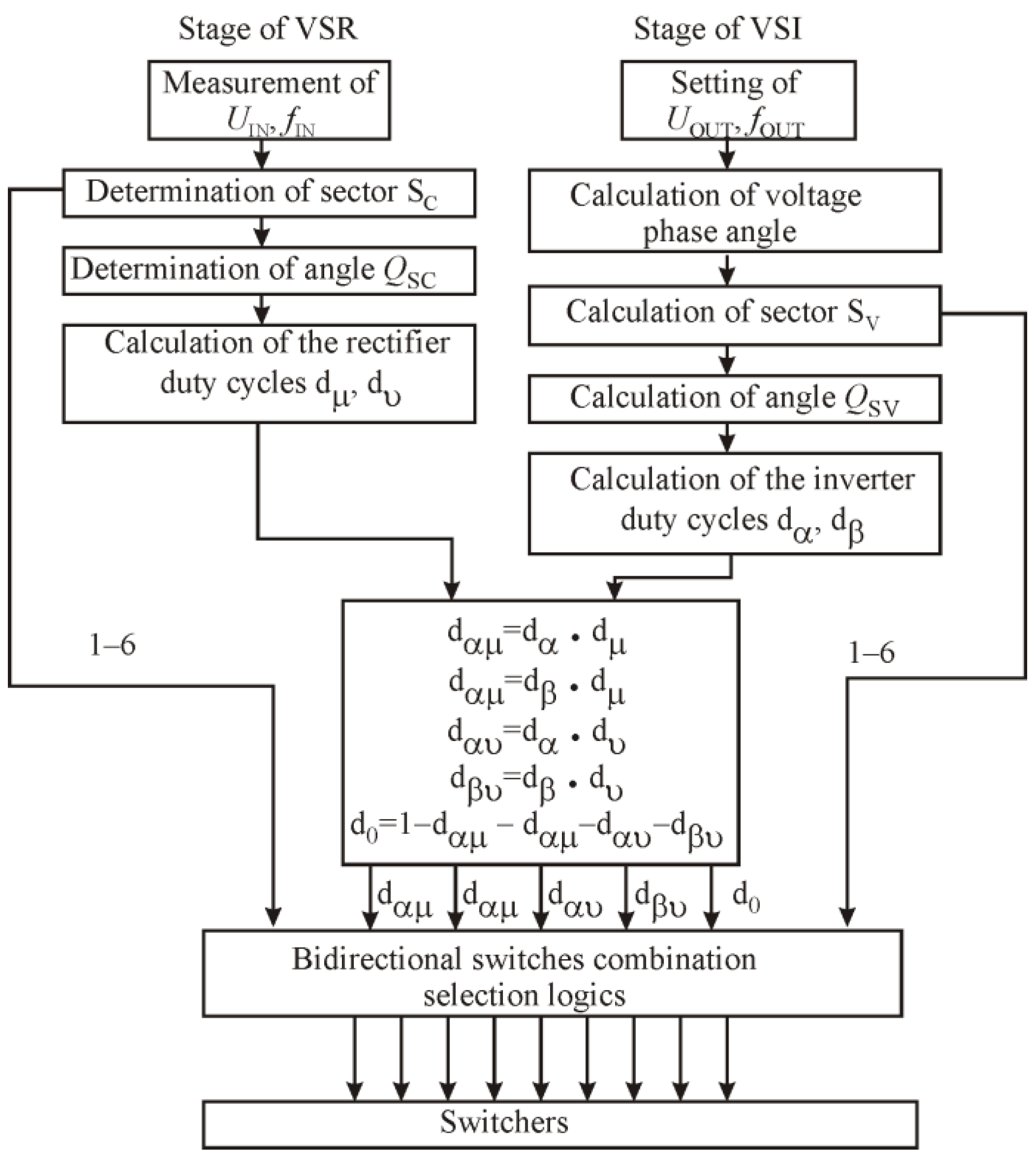
The control algorithm used for vector approximation is presented in Figure 3. According to the ISVM control strategy, it consists of two sequences representing the rectifier and inverter stages. Every sequence consists of sector determination and duty cycle determination. Both sequences are combined by the common duty cycle determination segment and bidirectional switchers control logic, as presented in Table 1.
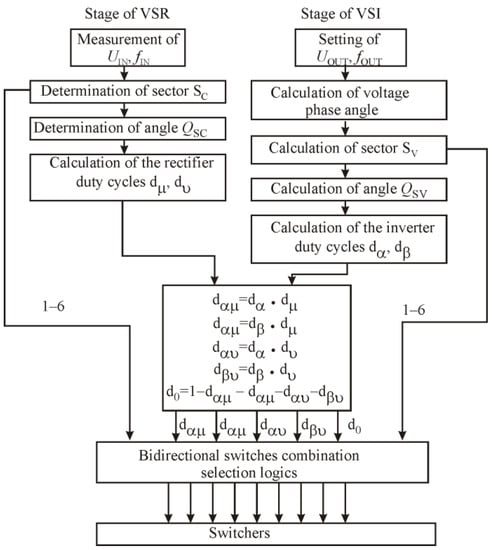
Figure 3.
Graphical interpretation of switcher’s combination selection algorithm.

Table 1.
Bidirectional switches combination logic.
One of the MC elements that has a major impact on the converter’s performance is its input harmonic filter [6]. The MC voltage and current are sinusoidal just in case an effective filter is applied to suppress switching ripple harmonics. The possible filter options are shown in Figure 1. The selection of this filter configuration and its components’ values is an important task that is neglected in many scientific works. The back-to-back converters traditionally used in energy systems with bidirectional power flow also have plug-in filters. However, the switching ripple harmonics generated by the back-to-back converters are significantly smaller than the switching ripple harmonics generated by the MC. This is related to the DC link in the back-to-back converters. Therefore, neither the back-to-back converters filter configurations nor their component values calculation methods are suitable for MC generated switching ripple harmonics filters. Until now, published papers have not provided studies on MC filters at bidirectional energy flow.
Therefore, the purpose of this research is to:
- to analyze higher harmonic filter types proposed in the publications;
- to select filter configurations suitable for use in MC converters;
- to investigate the efficiency of these filters by way of simulation with bidirectional energy flow.
2. The Switching Ripple Harmonics of Matrix Converter
Grid power quality is one of the concerns in the converter interfaced systems. During the operation of grid-connected MCs, space vector modulation methods are commonly used to maintain the switching of the power semiconductor devices. The power semiconductor devices produce switching ripple harmonics, which can cause harmonic distortions and reduce power quality in the utility grid. An output voltage waveform of the MC and Fourier series components of harmonic spectrum in the case of an ideal voltage supply are presented in Figure 4. The uppermost harmonics of the MC current are around the switching frequency and repeated frequencies.
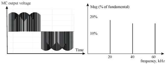
Figure 4.
An output voltage waveform and Fourier series components of the harmonic spectrum of space vector modulation-controlled MC.
Some research works have been conducted on switching ripple harmonics damping. Various types of filters are recommended for use on MC-based electric drives. In addition to switching ripple harmonic attenuation, the filters also maintain integration and coupling connection between the utility grid and the MC.
Several filter types, namely, L, LC, LCL and LLCL, are presented in publication [7] concerning grid connection of converters for photovoltaic plants. Unlike photovoltaic plants, the converter in another renewable-energy-based power system, such as a double-fed induction generator-based wind energy conversion system, provides bidirectional power flow [8]. The filter for such power systems has to be designed to damp ripple harmonics in the case of the bidirectional power flow. Most power quality studies discussing grid-tied renewable-energy-based power systems are related to conventional DC-link back-to-back voltage converters [9]. For the ripple harmonics damping, in such a power system the first order L-type filter is usually proposed. In this case, the inductor L properly interacts with the DC-link storage capacitor, as presented in Figure 5a [10]. For novel one-stage MC power systems, such interaction is impossible because of the absence of a DC-link storage capacitor.
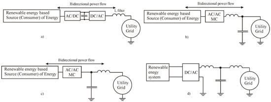
Figure 5.
Single-line diagram of filter component connection: (a) in the conventional AC/DC/AC converter-based power system; (b) CL filter component connections in the utility grid line (grid side capacitor); (c) LC filter component connections in the utility grid line (grid side inductor); (d) LCL filter component connection in the DC/AC—utility grid system.
Only a few studies of harmonic distortions for the novel one-stage MC in bidirectional power flow system are published. The permissible level of harmonics for the integration of renewable energy power plants into the utility grid is defined in publication [11]. Publication [12] indicate that the level of harmonics when connecting a filterless MC to the utility grid does not meet the requirements of the grid codes. It should be noted that the interaction of the power distribution line parameters (induction, capacitance) with the filter components have not been addressed in the studies mentioned above. Some authors suggest using widely applicable first order or second order filters but do not examine the effect of filter parameters on harmonic distortions [13]. The efficiency of the filter directly depends on the filter element connection point. Some authors suggest inserting filter components into a circuit connecting the MC and the utility grid, others—circuitry that connects renewable energy power sources and the utility grid. The efficiency of a filter by damping the harmonics depends on the direction of the transmitted power and the harmonic flow direction. Figure 5b presents the CL filter component connection diagram applied in voltage-source and current-source converters [14]. The CL filter capacitor is on the utility grid side. By combining this arrangement, the damping of the switching ripple harmonics becomes ineffective if the MC operates in power consumption mode with respect to the utility grid. Figure 5c presents the LC filter component connection diagram proposed in publication [15]. The filter capacitor is on the MC side. Connecting this way, the filter capacitor will form a lower impedance path for the switching ripple harmonics if the MC is in the power supply mode with respect to the utility grid. This would increase the current in the capacitors circuit.
Figure 5d presents the LCL filter component connection diagram proposed in publication [16].
The LCL filter should block MC-generated switching ripple harmonics, protecting the utility grid from their access. If LCL filter component values were calculated incorrectly, this could lead to unwanted oscillations.
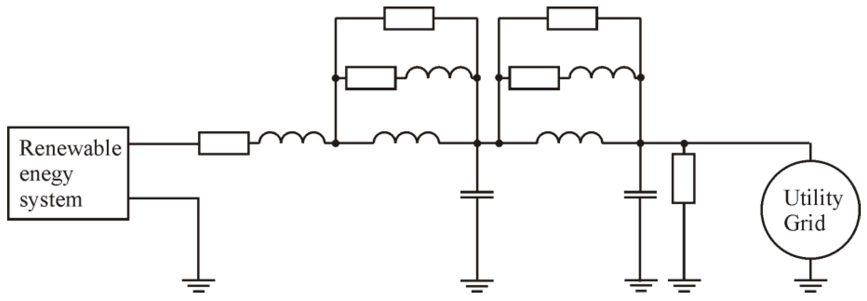
Figure 6 presents a two-branch filter component connection diagram proposed in publication [17].
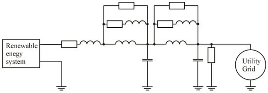
Figure 6.
Single-line diagram of two-branch filter component connection.
This type of filter has significantly higher component content than other filter topologies.
After reviewing a number of filter topologies, two main issues were raised:
Which filter topologies are suitable for switching ripple harmonics attenuation in the bidirectional power flow grid connected unit?
What is the influence of the utility grid parameters on filter attenuation characteristics?
These issues will be solved in further analysis.
3. Requirements for Switching Ripple Harmonics Filters
Some renewable energy devices, such as double-fed induction-generator-based wind power plants, can operate as energy consumers and as energy suppliers, depending on their operating mode. In such case, the MC must perform the bidirectional power transmission function and operate in both power consumption and power supply modes. In any of the above-mentioned modes, MC is the source of the switching ripple harmonics. To protect the utility grid from the MC-generated harmonics, the above-mentioned bidirectional power flow and operating modes must be taken into account.
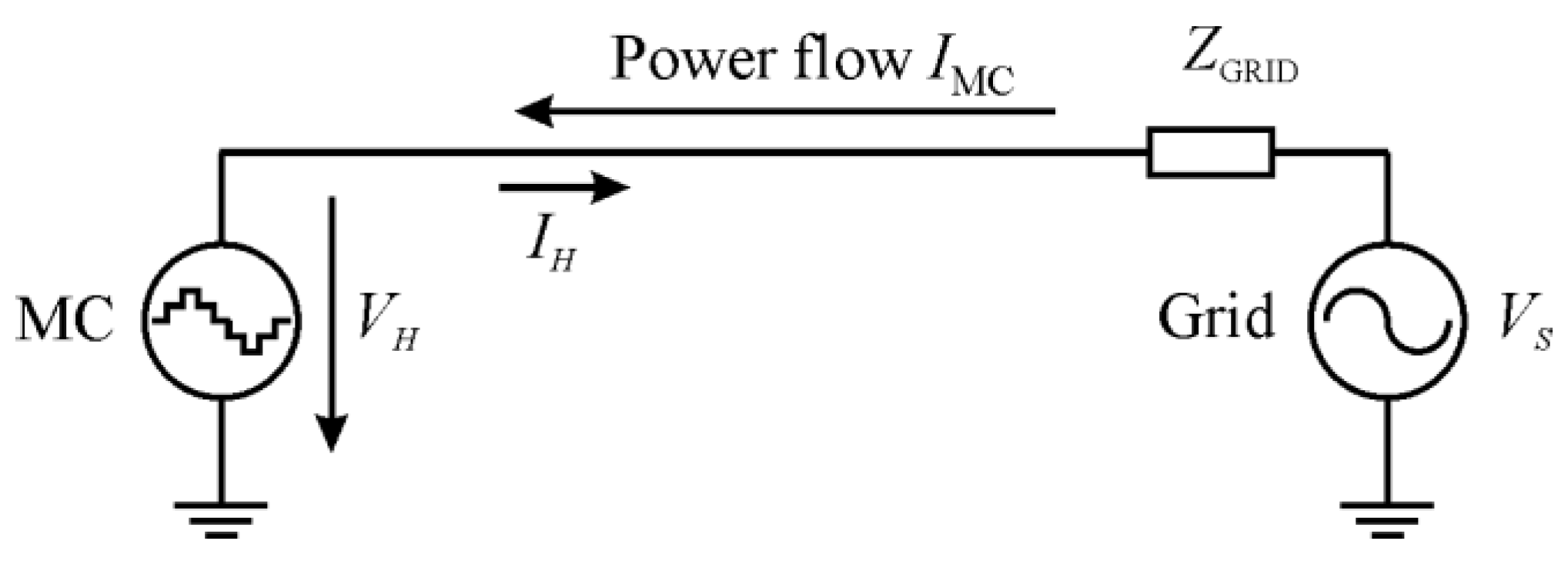
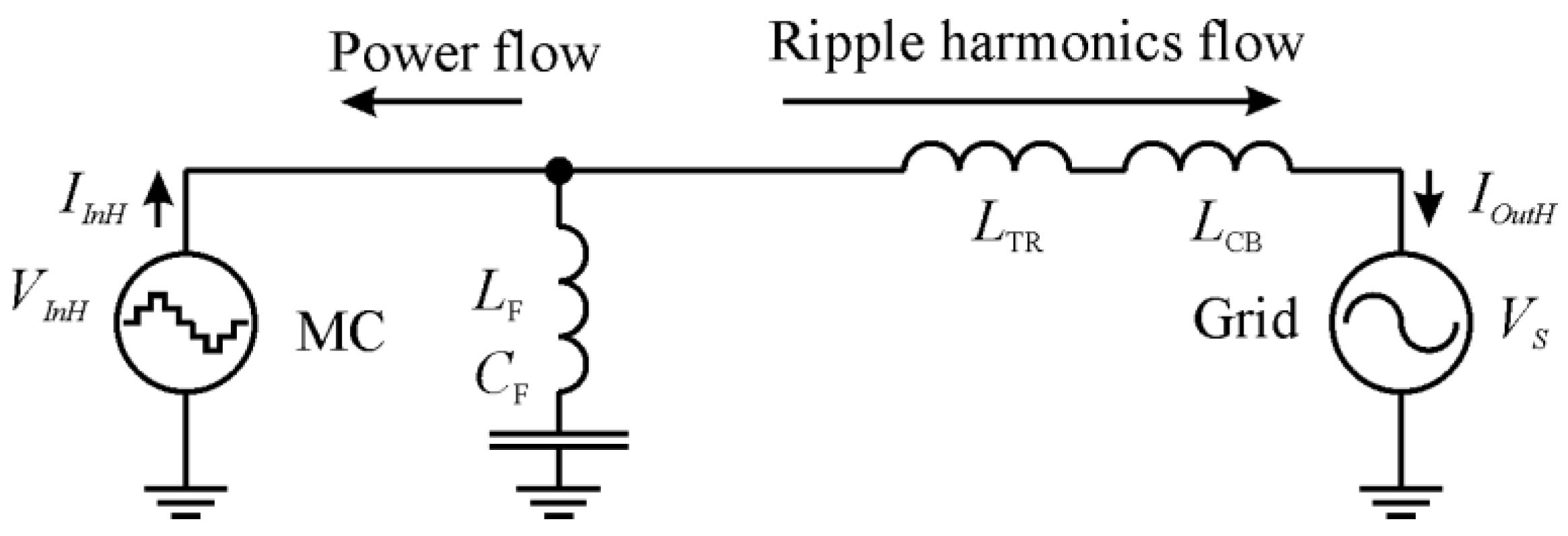
The generation of higher frequency switching ripple harmonics is directly related to the principle of the MC operation, based on the power semiconductor devices switching. The filter designed for the utility grid protection from the above-mentioned harmonics must form a conduction path for the grid frequency voltage and prevent the passage of the harmonic frequency voltage. In the equivalent diagram shown in Figure 7, the MC is depicted as a harmonic frequency current source. If the renewable energy device is connected to the utility grid via an MC without the filter, the ripple harmonics generated by the MC will be directly transmitted to the grid. The filter maintaining integration and the coupling connection between the utility grid and the MC have to prevent the penetration of the harmonics current IH into the grid.
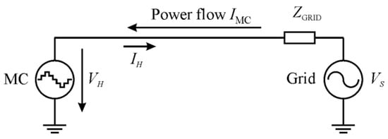
Figure 7.
A single-phase equivalent diagram of the power flow in the case of power consumption mode operating filterless MC.
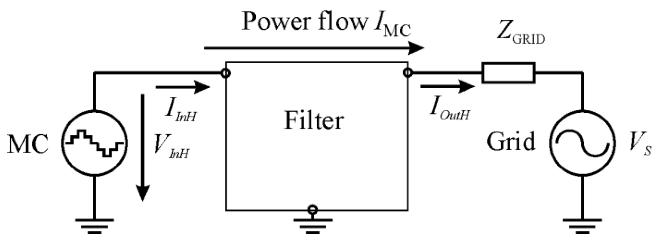
The power flow direction in the supply operating mode and via filter equipped MC grid connected renewable energy device, is shown in Figure 8. In this case, the power flow direction coincides with the harmonics current direction. The filter elements shunt the harmonic current, resulting in a significantly lower amount of ripple harmonics.

Figure 8.
A single-phase equivalent circuit diagram of the supply mode operating filter equipped MC.
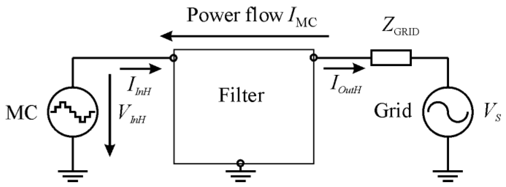
The power flow direction in the consumption operating mode and via filter equipped MC grid connected renewable energy device, is shown in Figure 9. In this case, the power flow direction does not match the harmonics direction. The direction of the power flow has changed while the current direction of the harmonics remains the same. It follows that the same filter topology can be used to attenuate the harmonics.
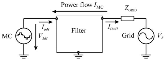
Figure 9.
A single-phase equivalent circuit diagram of the consumption mode operating filter equipped MC.
As can be seen from Figure 8 and Figure 9, the MC operating in the power supply and power consumption modes can be considered as a source of harmonics. Regardless of the power flow direction, and in the same renewable energy device operation mode, the value of harmonic current IH remains unchanged:
Since the generation of switching ripple harmonics is related to the principle of the MC operation, the filter must form the conduction path for the current IinH and not interrupt the flow of IinH; otherwise the MC would not work properly because of the unlimited growth of ripple harmonics voltage VH. As presented in Figure 8 and Figure 9, the filter has to create the conduction path to neutral for IinH with impedance lower than ZGRID. In addition, the level of VInH must decrease less than VH (Nomenclature):
In constructing a conduction path to neutral, the filter must prevent the ripple harmonics from penetrating the grid:
The harmonics level in the input of the filterless MC is determined by the utility grid impedance ZGRID (Figure 7).
The harmonics level in the input for the filter composed MC is determined by the filter impedance ZinF (Figure 8 and Figure 9).
The filter impedance has to be less or equal to the utility grid impedance:
According to this, the filter input impedance is:
Furthermore, the filter input impedance for the frequency of the utility grid ωs must be as high as possible:
The filter current transfer ratio H2(jω) must be as low as possible to conduct a current of utility grid frequency ωs:
Based on the foregoing statements, these key requirements that the filter should meet in the MC-based bidirectional power flow implementing utility grid connected equipment, are formulated:
- the filter input impedance H1(jω) has to meet the requirements presented in Equations (10) and (11);
- the filter current transfer ratio H2(jω) has to meet the requirements presented in Equations (12) and (13).
4. Characteristics of the Most Commonly Used Filters
Several types of filters, namely, L, LCL and LC-type, are provided in the publications concerning bidirectional power flow implemented, grid connected voltage source inverters and back-to-back converters [18,19]. This paper examines the possibilities of using these types of filters to attenuate the ripple harmonics in the bidirectional power flow implemented utility grid connected MC. This is done by examining the frequency response of the filters, taking into account the nature of the MC-generated harmonics, and the bi-directional power flow through the MC.
4.1. L Filter Characteristics
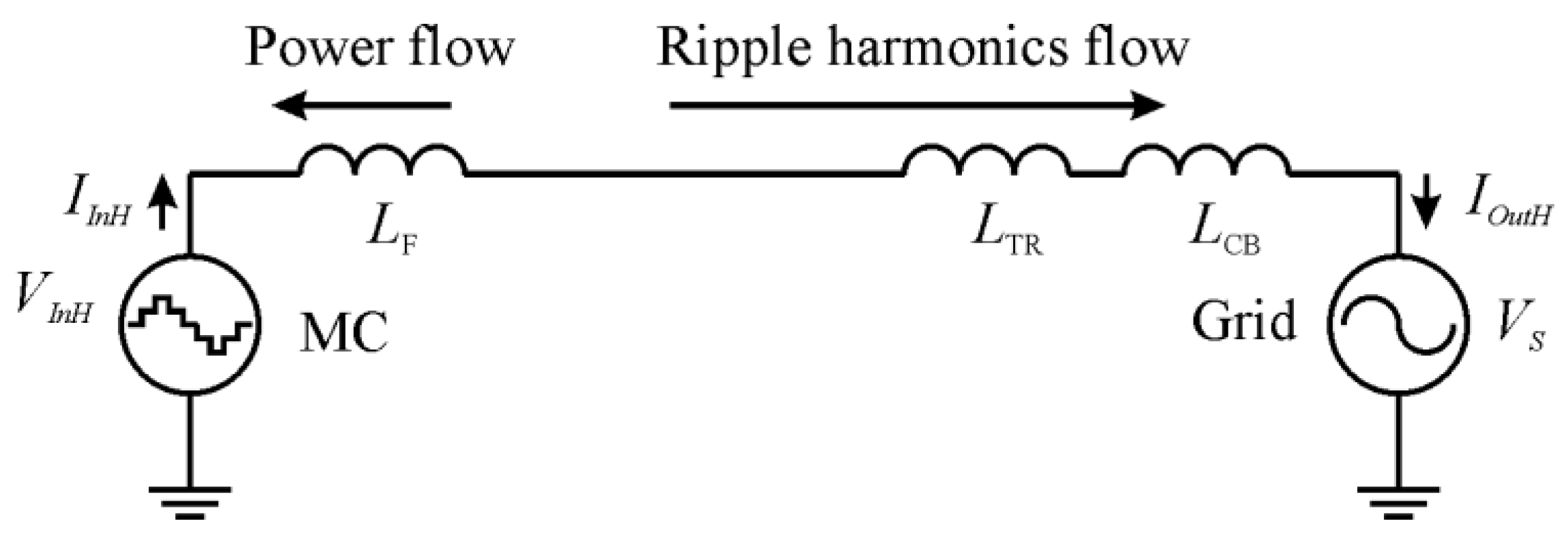
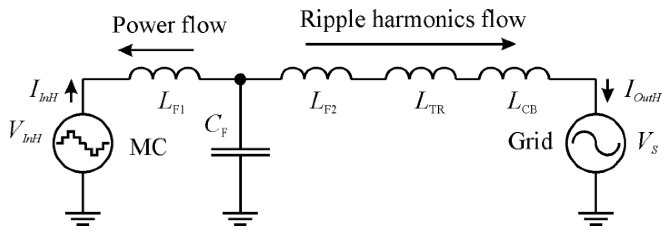
As described in the reviewed study [18], a first order L-type filter operates as a filter interface between the converter, which is operating as an energy source and the utility grid, to smooth the ripple harmonics. Advantages, such as simple design and lower number of filter components, are shown. The inductor L properly interacts with the DC-link storage capacitor of the conventional DC link-based back-to back converter. In this paper, the L filter application in bidirectionally operating matrix converter for renewable energy application was studied. An absence of the DC-link storage capacitor in the MC complicates the situation. This interaction, which occurred using a conventional DC link-based back-to-back converter, is not possible in the case of the MC use. The single-phase equivalent circuit diagram of the three-phase grid-connected MC with an output L filter is presented in Figure 10, where LF is the inductive filter component.
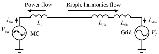
Figure 10.
Single-phase equivalent diagram of the three-phase grid-tied MC with an output L filter.
The impedance of the filter is:
The harmonics current attenuation is:
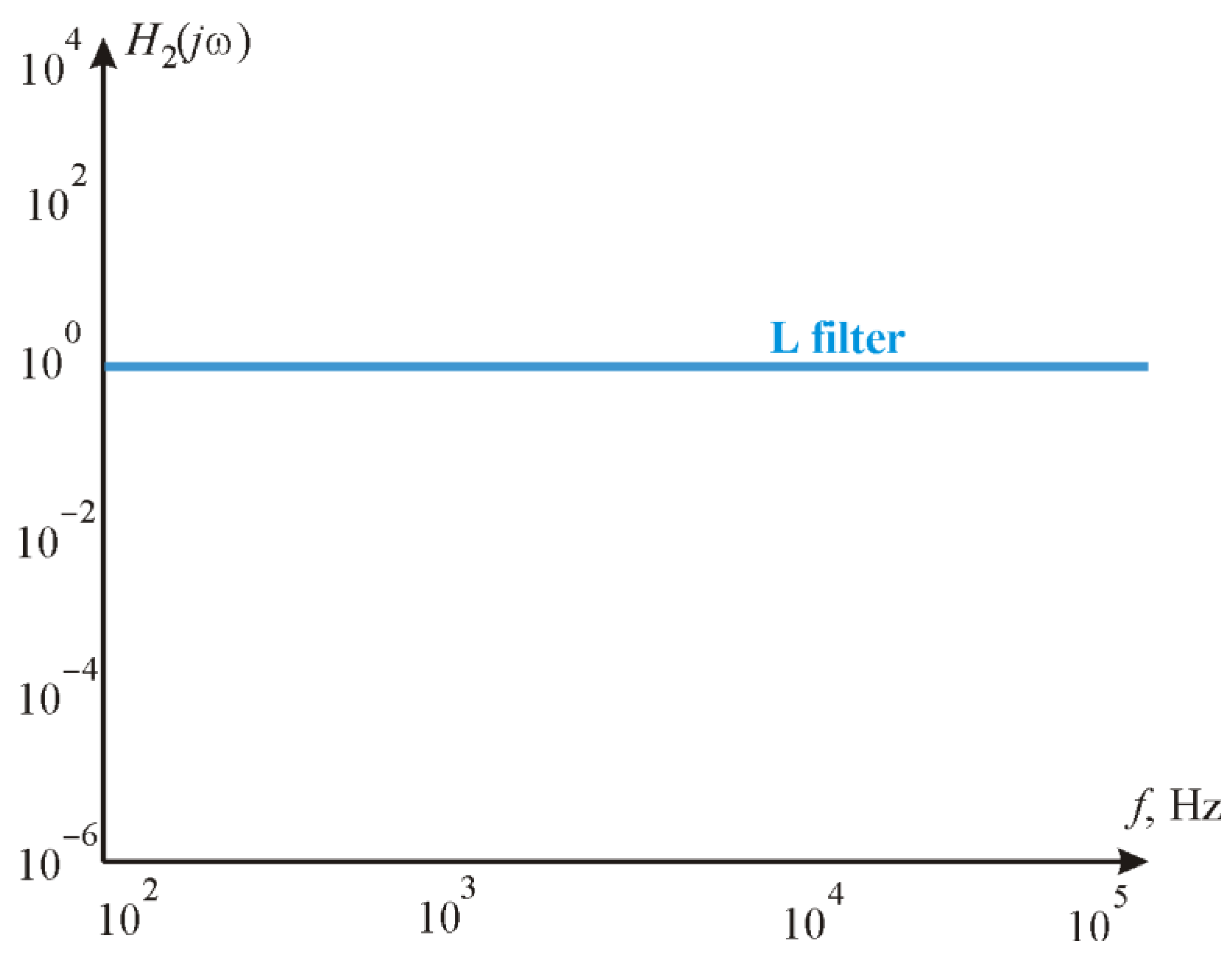
Whether the L type filter meets the requirements that were formulated before can be determined by comparing the filter impedance to different frequencies—the impedance for an MC ripple harmonics frequency and impedance for the utility grid main frequency. The impedance of the L filter (14) for the MC ripple harmonics frequency is lower in comparison with the impedance for the frequency of the utility grid voltage. This indicates that the L filter does not meet the requirements for the impedance, which is given in Equation (11). As seen from Equation (17), according to the transfer rate, the L filter does not create a barrier and allows the MC-generated harmonics to penetrate the utility grid. This shows that the L filter does not meet the requirement given in Equation (12). The same conclusion can be drawn from the L filters frequency response shown in Figure 11. Based on these two findings, it can be stated that the L filter is not applicable for switching ripple harmonics damping in the bidirectionally operating MC.
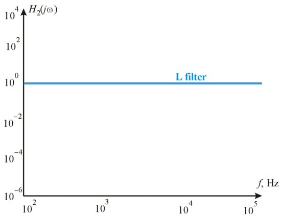
Figure 11.
Frequency response H2(jω) of the L filter.
4.2. LCL Filter Characteristic
Another filter topology is LCL, which has recently taken the place of the most conventional inverter application [19]. According to the studies, despite having smaller capacitance and inductance values in comparison with the aforementioned L filter, the LCL filter can attenuate the ripple harmonics more efficiently. Furthermore, the voltage drop stemming from the harmonics across the filter is smaller than in the L filter. Despite the earlier mentioned advantages, the LCL filter has some disadvantages in comparison with the L filter. These are risk of resonance occurrence, phase lag and system design complicacy.
The single-phase equivalent circuit diagram of the three-phase grid connected MC with an output LCL filter is presented in Figure 12, where LF1, LF2 and CF are the inductive and capacitive filter components.
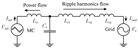
Figure 12.
Single-phase equivalent diagram of a three-phase grid-tied MC with an output LCL filter.
The impedance of the LCL filter can be calculated according to the equation:
An induction of the filter elements and the utility grid elements such as transformer, distribution lines and connection cables can be calculated accordingly:
The output-voltage-based frequency response can be calculated by:
The current transfer ratio can be calculated by:
According to Equation (18), the impedance of the LCL filter depends strongly on the L1 value. The input impedance of this filter for frequency of the harmonics drops down and the main reason for this is the value ω3L1 in denominator of the equation. This shows that the LCL filter does not meet the input impedance requirement presented by Equation (11).
As shown in Equation (20), the LCL filter transfer ratio H2(jω) decreases with the frequency of the MC-generated ripple harmonic frequencies. This indicates that the LCL filter meets the second requirement associated with the current transfer ratio.
Despite meeting the current transfer ratio requirement, the LCL filter is considered not applicable for switching ripple harmonics damping in the bidirectionally operating MC.
4.3. LC Filter Characteristic
Another topology for an inverter or back-to-back converter switching ripple filtering proposed in publication [20] is an LC filter. The capacitor is connected to the inductor to create a low impedance path at high frequency ripples.
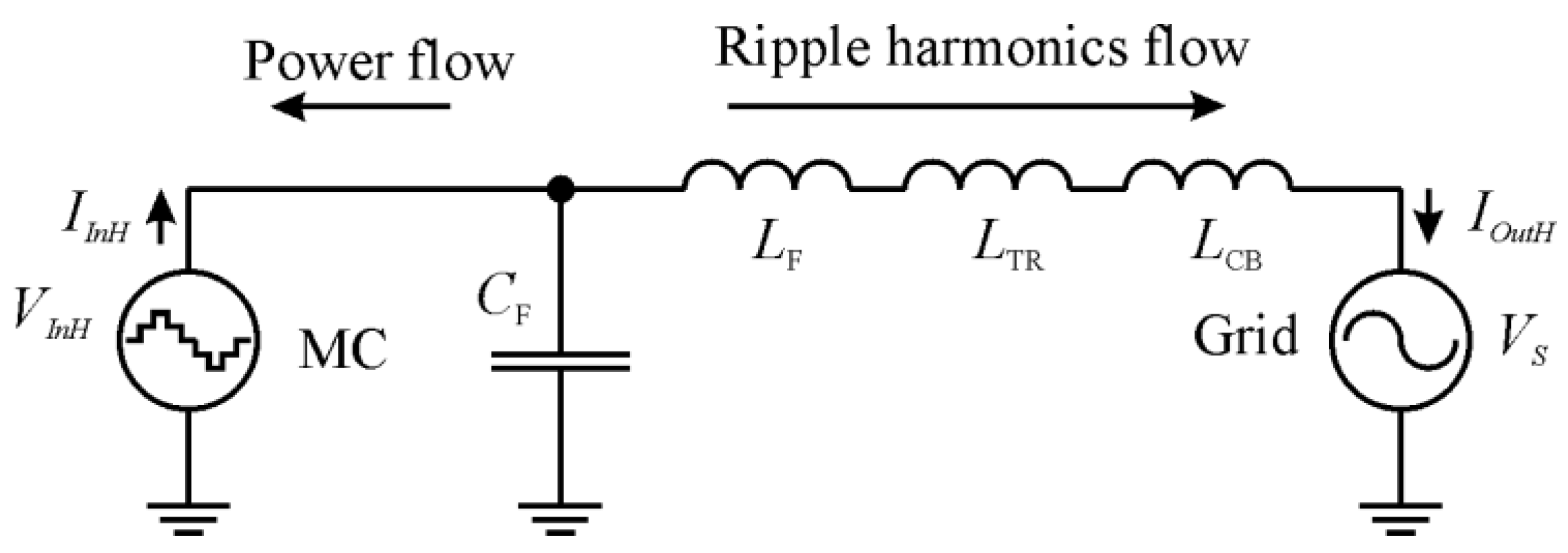
The single-phase equivalent circuit diagram of the three-phase grid-connected MC with an output LC filter is presented in Figure 13, where LF and CF are the inductive and capacitive filter components.

Figure 13.
A single-phase equivalent diagram of the three-phase grid-tied MC with an output.
As Equation (20) in the aforementioned LCL filter study shows, the current transfer ratio of the LCL does not depend on the inductor L1 value. According to the key requirements the filter impedance should be as high as possible, H1(jω)⟹ max ⟹ ∞. In this regard, the LC filter can be considered as a simplified LCL filter version. The MC operating in power consumption mode can be considered as a source of current that generates the high frequency switching ripple harmonics. Therefore, there is no necessity to limit the current across the filter capacitor C by the inductor L1. The impedance of the LCL filter in the case of L1 = 0; L2 = LF2 + LTR + LCB is:
The values of the filter components are usually calculated based on the assumption that their operating frequency is significantly higher than the resonance frequency, ω ≫ ωRes. Taking into account that and , the filter impedance is:
As Equation (22) shows, the LC filter impedance for ripple frequencies is sufficiently higher in comparison with the impedance for the frequency of the utility grid voltage main harmonics. It means that the LC filter meets the input impedance requirements for the ripple harmonics damping described in (10) and (11).
The current transfer ratios of the LC filter are calculated by:
As Equation (23) shows, the LC filter meets the current transfer ratio requirement for the ripple harmonics damping described in (12) and (13).
Since both key requirements for the filters that were formulated before are met, it can be argued that the LC filter is applicable for switching ripple harmonics damping in the bidirectionally operating MC.
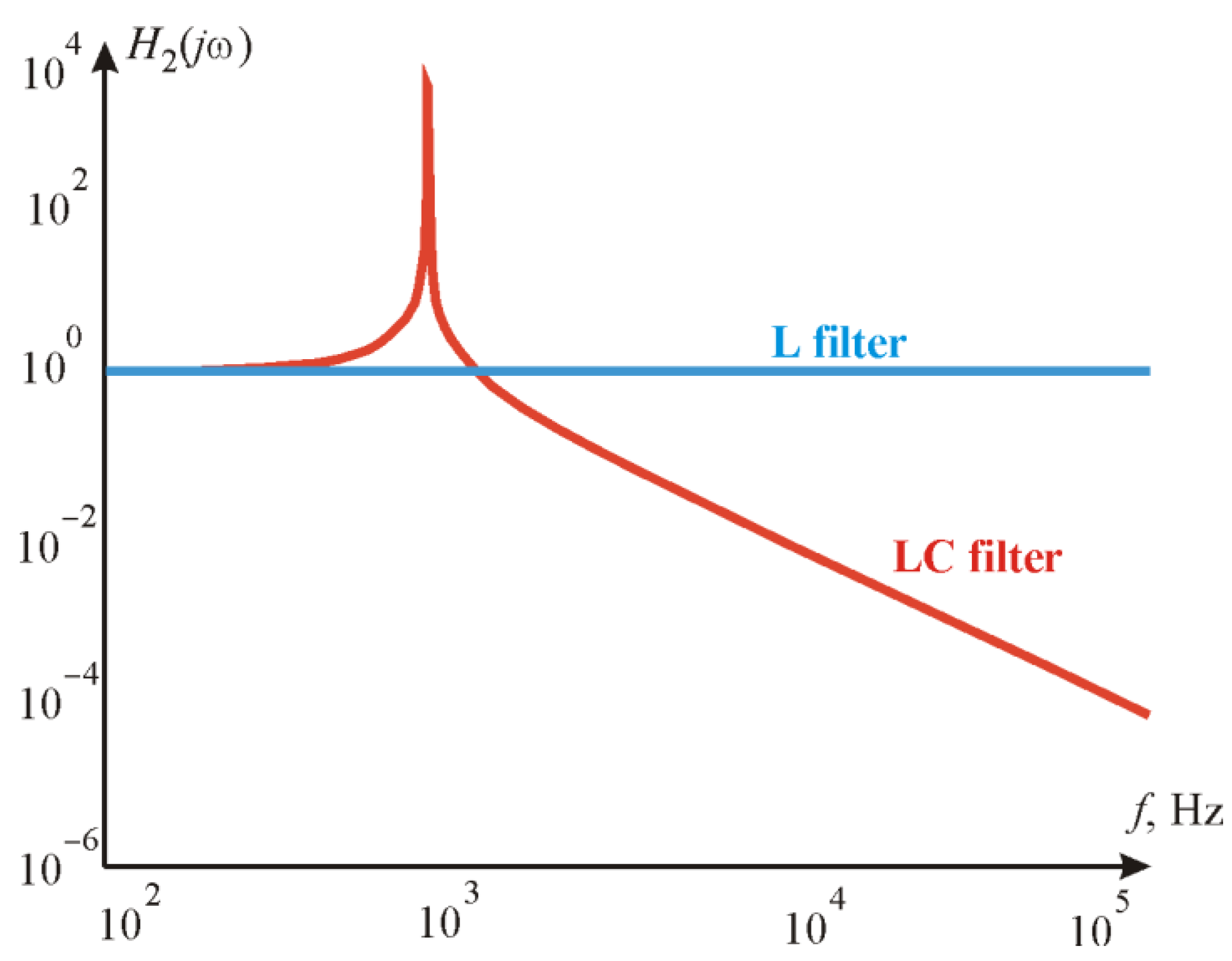
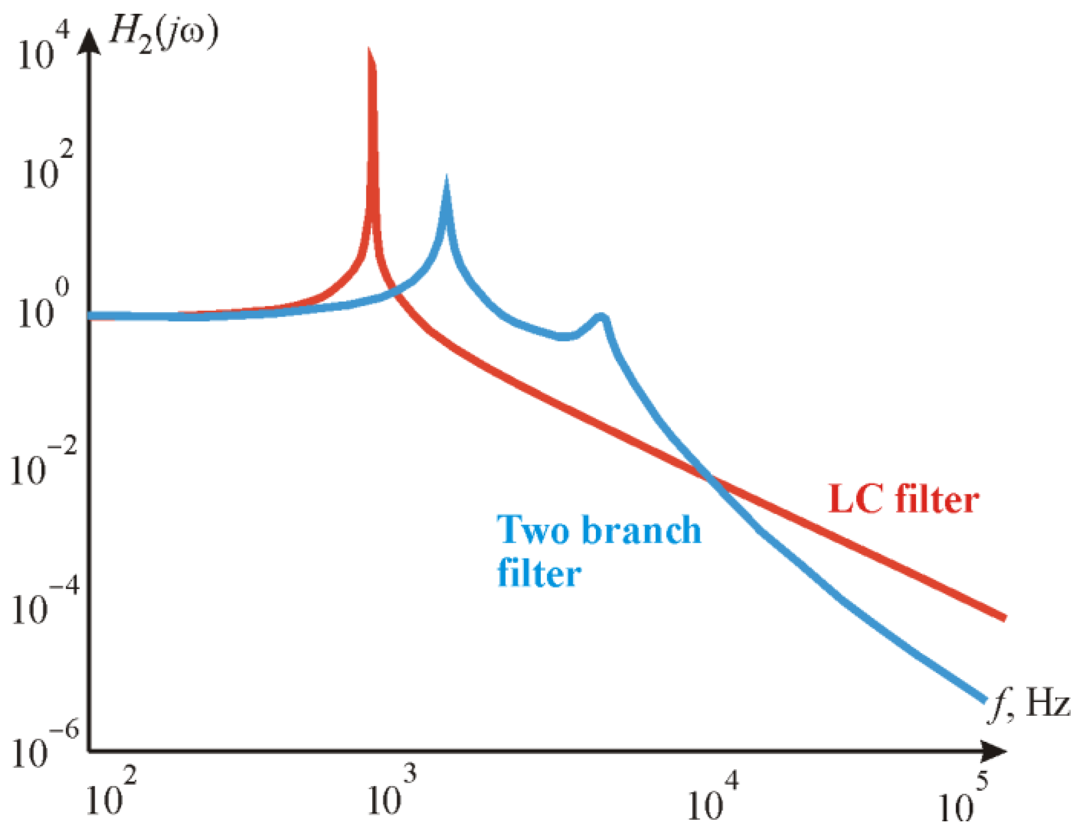
According to the LC filter frequency response H2(jω) presented in Figure 14, the LC filter transfer ratio is below the L filter transfer ratio in almost the entire frequency range, except for the frequency area (104–105 Hz) in which the MC-generated harmonics concentrate. In this frequency range, the LC filter attenuates the MC-generated harmonics most effectively.

Figure 14.
Frequency response H2(jω) of the LC filter.
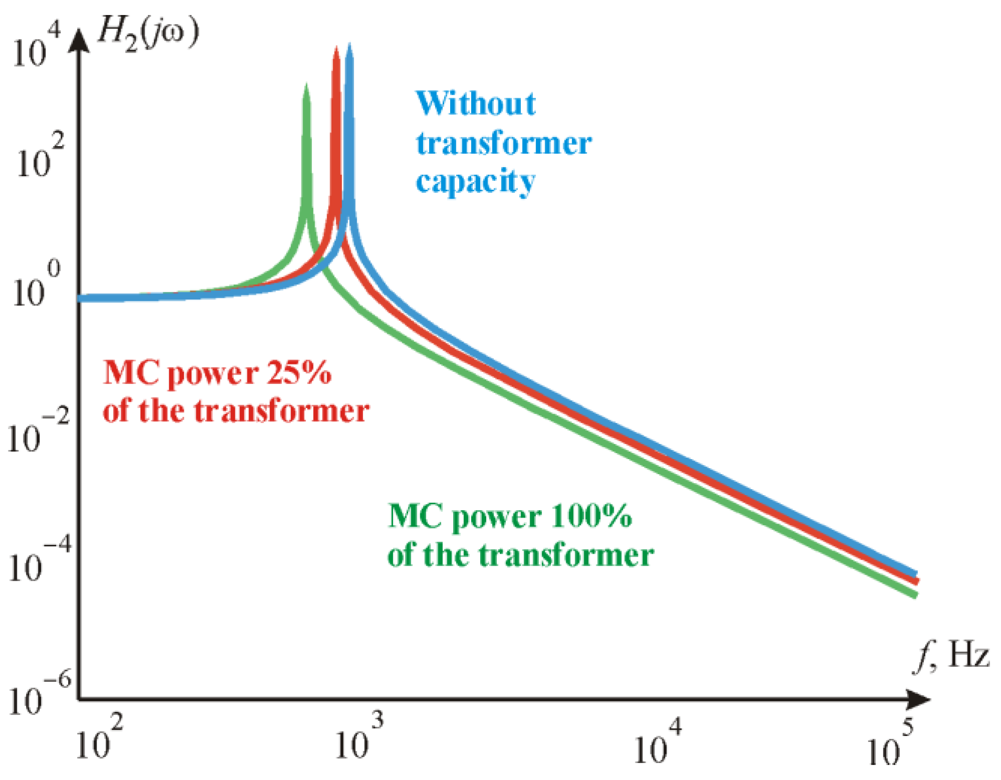
Figure 15 shows the effect of the utility grid transformer impedance on the filter transfer ratio H2(jω). According to the frequency response, it is seen that the influence of the utility grid transformer impedance depends on the ratio of the transformer and the MC capacities. It is also seen that the maximum transfer ratio is achieved when the ratio of the transformer to the MC power is 100%. It means that the utility grid impedance as well as the power distribution line impedance can significantly increase the LC filter’s ability to attenuate switching ripple harmonics.

Figure 15.
The effect of the utility grid transformer impedance on the filter transfer ratio H2(jω).
4.4. Resonant Filter Characteristic
The application of the resonance filters to the attenuation of the MC-generated switching harmonics is rarely seen in publications. The resonance filter is analyzed only in publication [21]. According to this study, the resonant filter provides a very low impedance path and absorbs the high frequency harmonic currents. Regarding the frequency of the utility grid voltage, the resonant filter can act as a reactive power compensator.
The voltage resonant filter consists of a serial resonant circuit connected in parallel to a converter. The single-phase equivalent circuit diagram of the three-phase grid-connected MC with a voltage resonant filter is presented in Figure 16, where LF, and CF are the inductive and capacitive filter components.

Figure 16.
A single-phase equivalent circuit diagram of the resonant filter component connection.
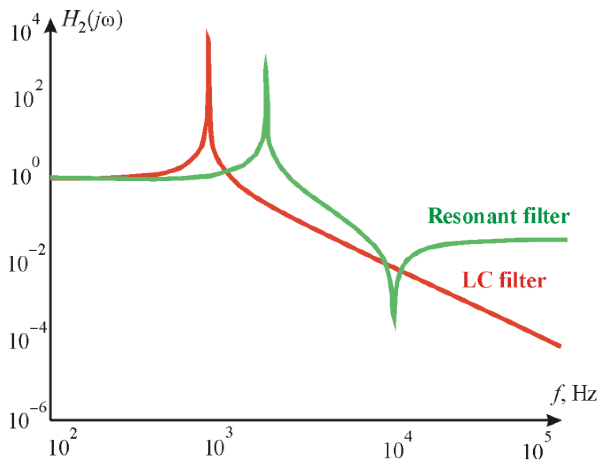
Component values in this type of filter are calculated to provide as little impedance ZRFIL as possible. The nature of the ZRFIL must be active. Theoretically, the H1(jω) of the voltage resonance filters is extremely small in the narrow frequency range. This means that the voltage-resonance filters are only intended to suppress the narrow-band harmonics. In Figure 17, the voltage resonance and the LC filter frequency responses are presented. When comparing the frequency response, it is seen that the voltage resonance filters are ineffective in suppressing harmonics that are above and below the resonant frequencies.
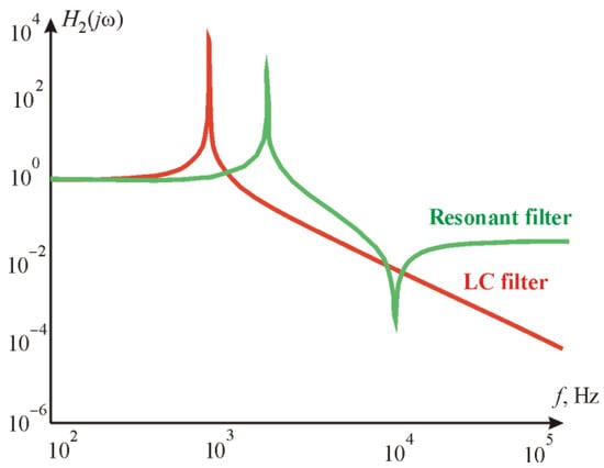
Figure 17.
Frequency response H2(jω) of the voltage resonant filters.
As Equations (26) and (27) show, in the case of , the voltage resonant filter meets the requirements described in (10) and (12). However, the requirements are only met in a special case of , that is, only when the frequency range is very narrow and close to the resonant frequency ωRES.
The voltage resonant filter is appropriate for damping the harmonics of frequencies relatively close to the frequencies of the electrical grid, it means k = 3rd, 5th and 7th harmonics. The frequency response of the resonant filter is sharp and upright and this filter is effective on harmonics with frequencies close to grid frequency fS and higher k*fS. The MC-generated harmonics have a different spectrum of frequencies. As shown in the Fourier series (Figure 4), the MC input and output currents have a significantly higher frequency spectrum over the utility grid frequency: fS <≤ f, H1(jωS) << H1(jω). In addition to this, the spectrum is considerably wider. The resonant filter meets the requirements for a very narrow frequency range. As a result, the resonant filter is considered as not applicable for switching ripple harmonics damping in the bidirectionally operating MC.
4.5. Two-Branch Filter Characteristic
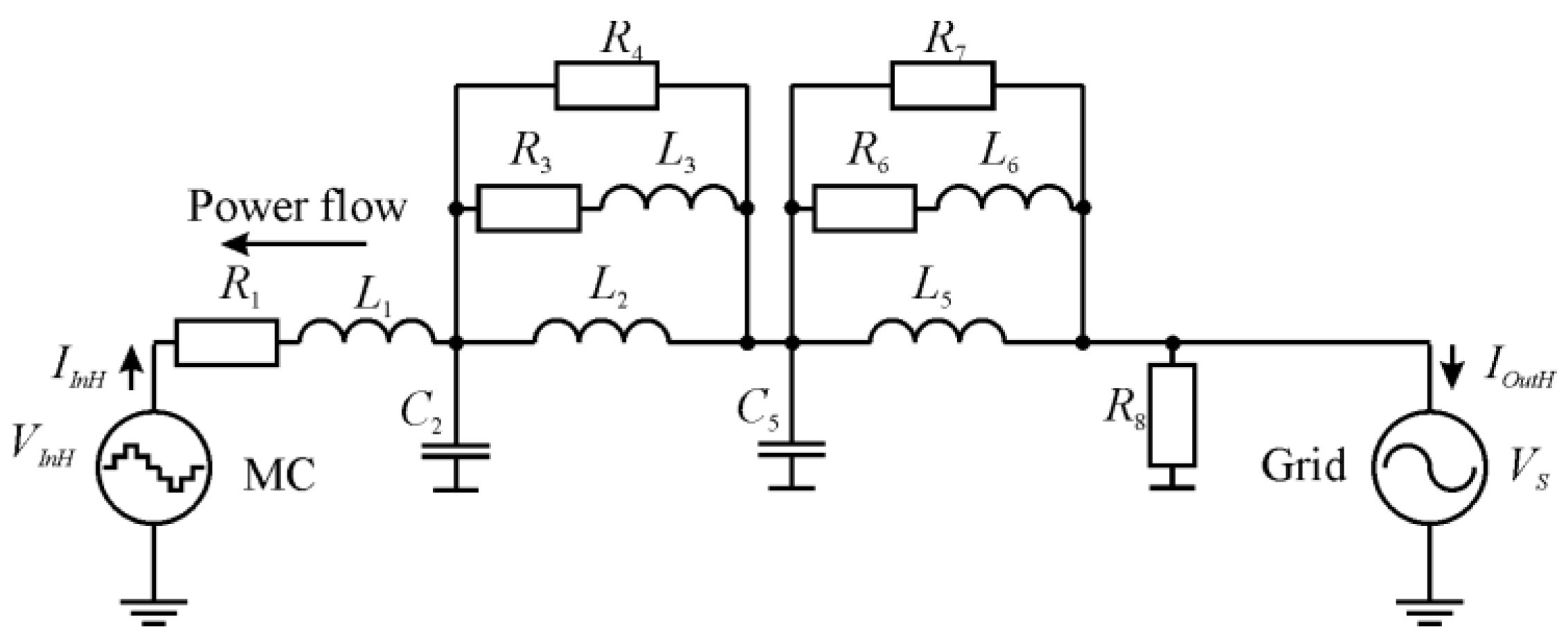
Publication [21] introduced one of the rarely applied filter topologies—the two-branch filter. This study evaluated a possibility of applying this topology to the bidirectionally operating MC. The single-phase equivalent circuit diagram of the three-phase grid-connected MC with a two-branch filter is presented in Figure 18, where L2, L3, L5, L6, R2, R4, R6, R7, and C2 and C5 are the active, inductive and capacitive filter components.
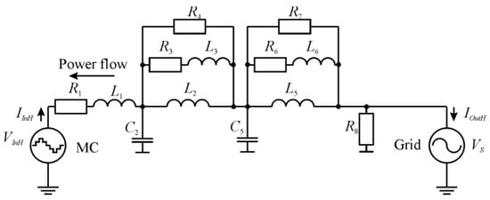
Figure 18.
A single-phase equivalent diagram of a two-branch filter component connection.
A comparison of the frequency response of the two-branch filter with the frequency response of the previously analyzed LC filter was performed to evaluate its applicability. The same L and C values were maintained. Therefore, an equation sequence analysis was carried out.
The frequency response of the filter is calculated under the equation sequence:
Figure 19 shows a frequency response of the two filters. These are the two-branch filter and the LC filter. Due to the largest number of components, the two-branch filter components’ L2, L5, C2 and C5 calculated values are significantly lower in comparison with the LC filter component L and C values. The two-branch filter component values are calculated based on the impedance and capacitance ratios L2 = L5 = L/3; C2 = C5 = C/3. The frequency responses show that the damping efficiency of the switching ripple harmonics of the carrier frequency 104 Hz are almost equal for both the LC filter and the two-branch filter. For the higher frequencies, the current frequency response shows an advantage of the two-branch filters—the damping efficiency of this filter is higher in comparison with the LC filter. The application of the two-branch filter is determined only by the component weight and the price factor.
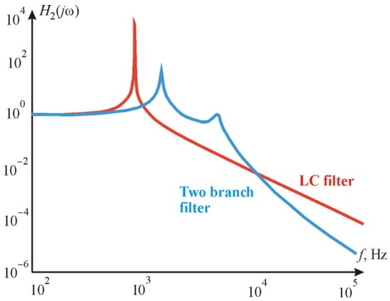
Figure 19.
Frequency response H2(jω) of the two-branch filter.
Because all of the requirements for the ripple harmonics damping described in (8–11) are met, the two-branch filter is considered applicable for switching the ripple harmonics damping in bidirectionally operating MC for renewable applications.
5. Simulation Studies
The simulation was developed in Matlab/Simulink. The Matlab/Simulink model of the bidirectionally operating MC consists of four parts. The first part contains the utility grid and distribution lines components’ simulation blocks—voltage source plus impedance of utility grid. The Matlab/Simulink block three-phase voltage source in series with RL branch was used to simulate these components. The second part contains blocks for filter element simulation (Figure 20). Matlab/Simulink blocks implementing a three-phase series RLC branch were used to simulate filter components. The “Branch type L “setting was selected to simulate the filter inductance. The “Branch type C” setting was selected to simulate the filter capacity.
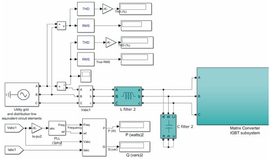
Figure 20.
The Matlab/Simulink components implementing utility grid, distribution lines and the filter.
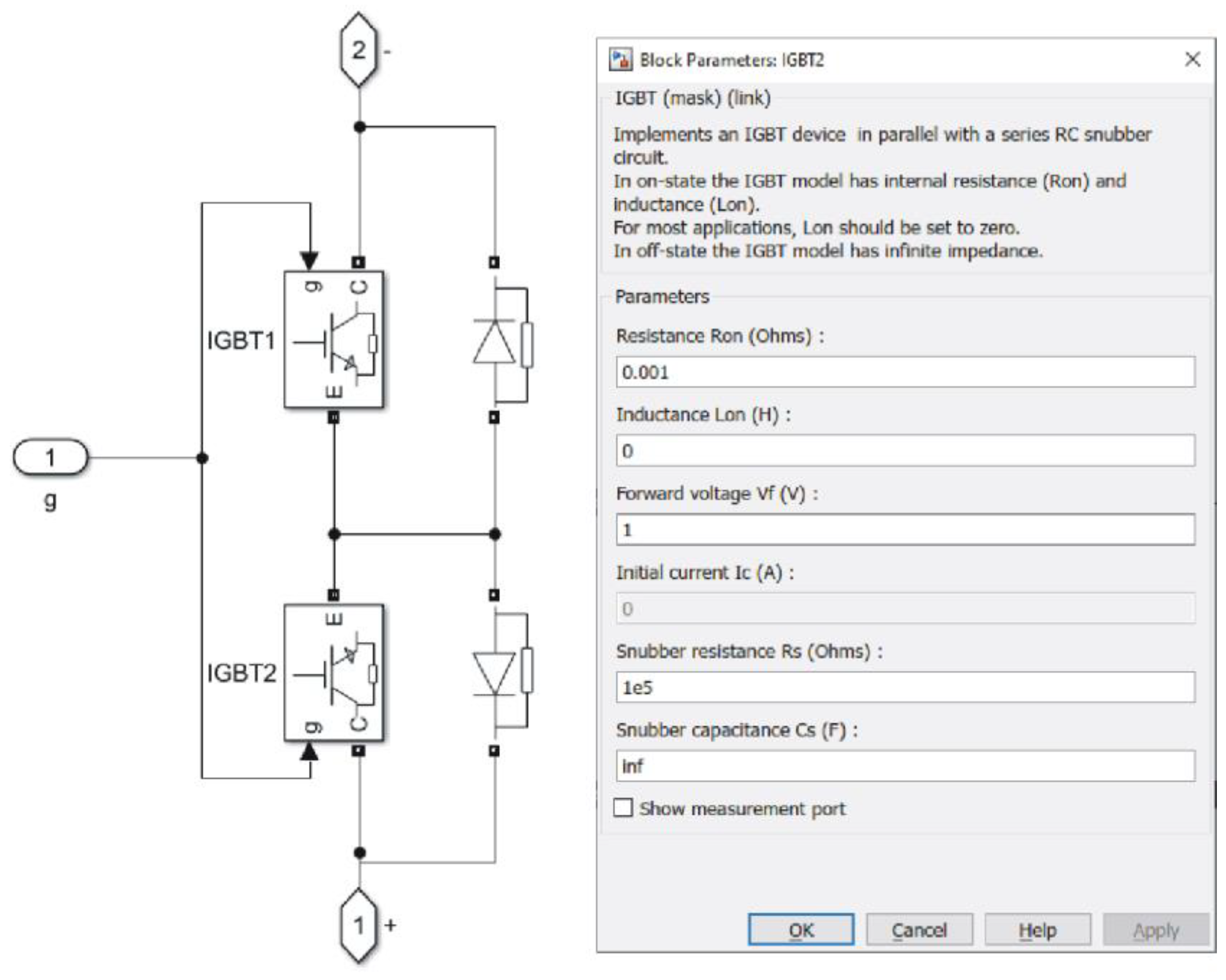
The third part contains nine ideal bidirectional switches of the MC and space vector modulation control modules (Figure 21). To simulate the ideal bidirectional switches of the matrix converter, blocks were used that implement an IGBT device in parallel with a series RC snubber circuit. Standard Matlab/Simulink subsystems running Park and Clarke transformations were used to simulate the space vector modulation system. Using the standard logic and comparison blocks, the sector separation subsystem was implemented.
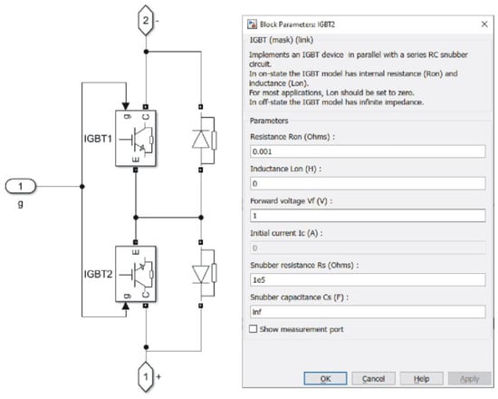
Figure 21.
The Matlab/Simulink components implementing the ideal bidirectional switches.
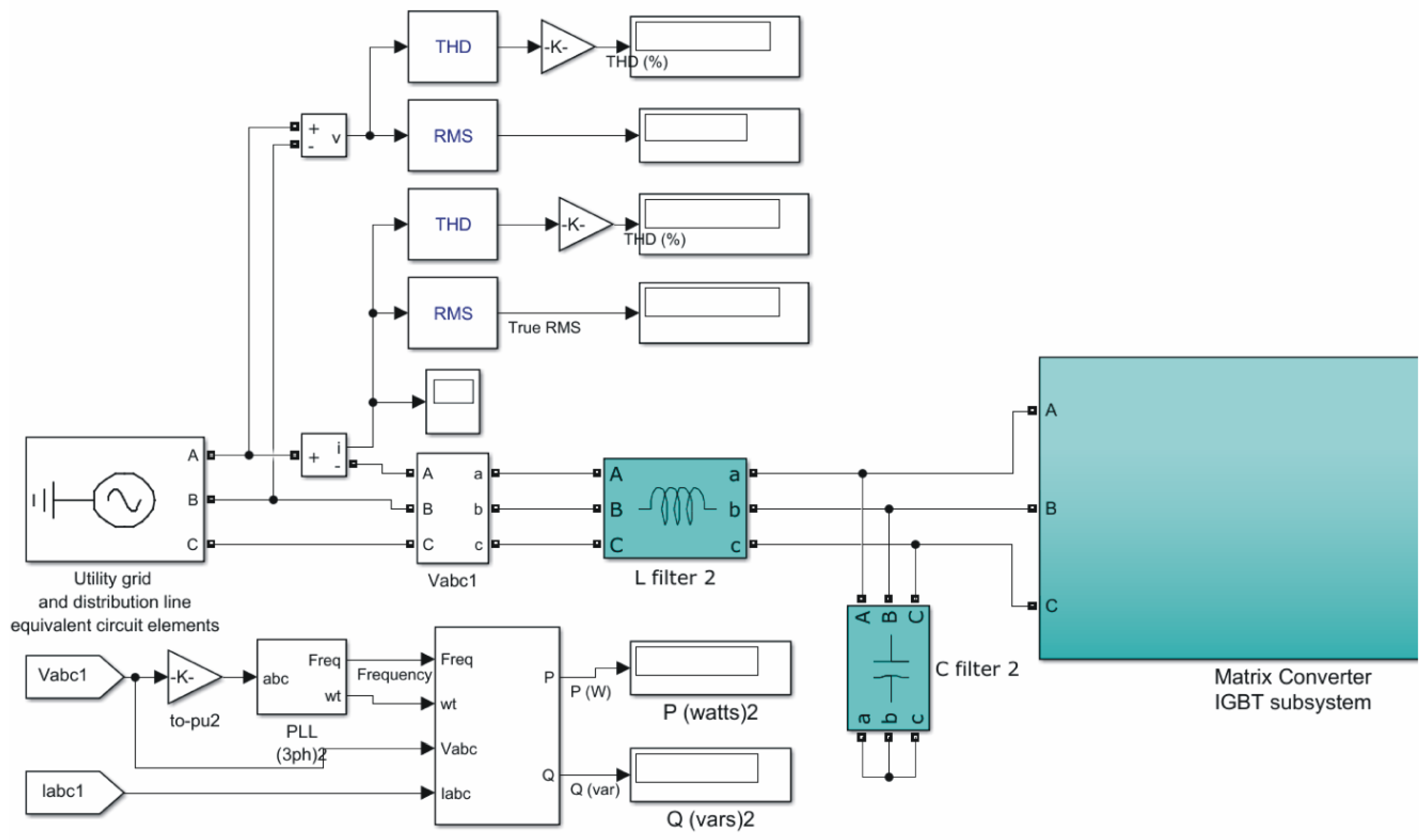
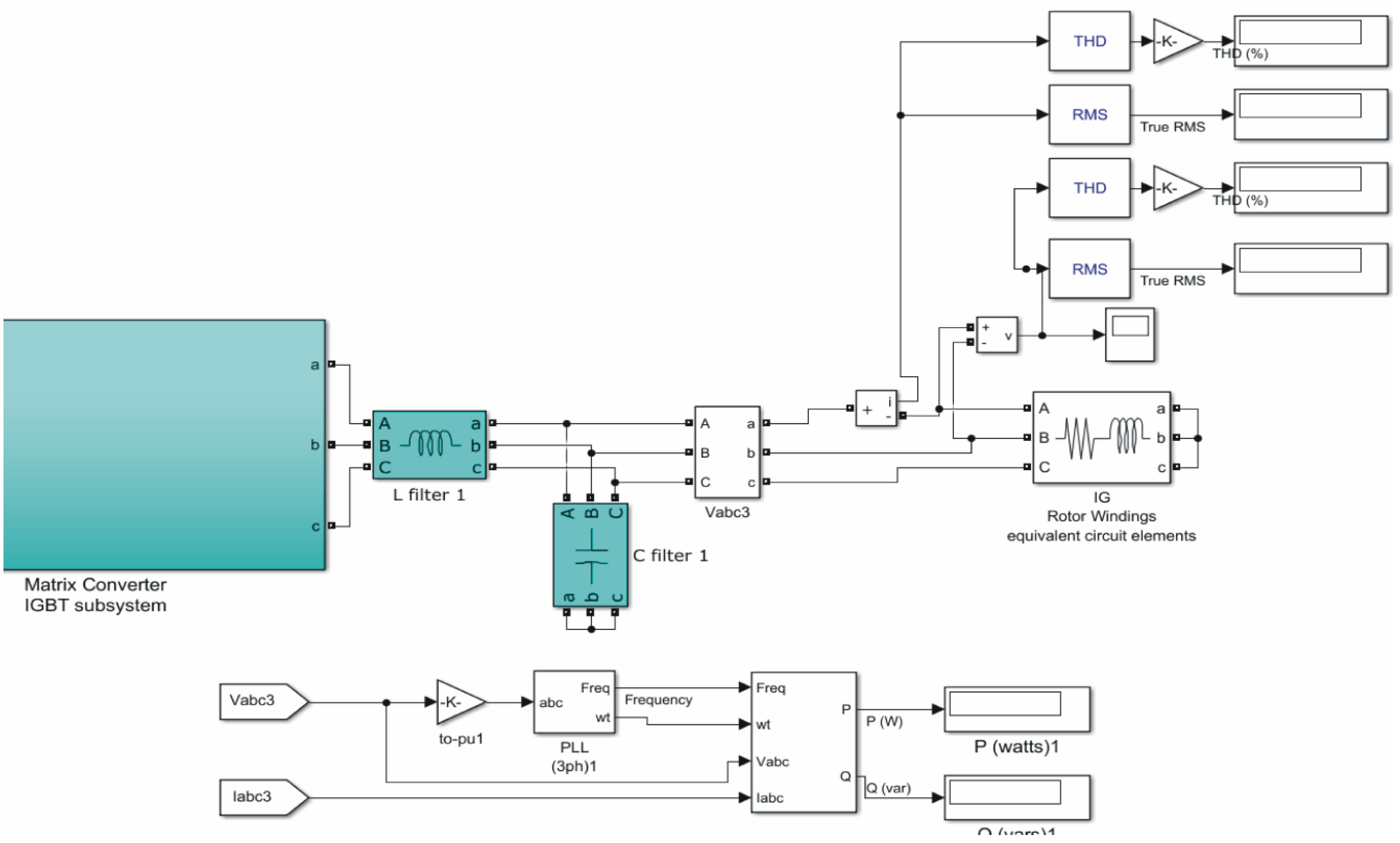
The fourth part contains right side LC filter and renewable energy source (consumer) components (Figure 22). Matlab/Simulink blocks implementing a three-phase series RLC branch were used to simulate filter components.
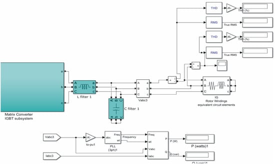
Figure 22.
The Matlab/Simulink components implementing energy consumption side elements.
According to IEEE recommended practices and requirements for harmonic control in electrical power systems, it is recommended to use filter component values such that the filter reduces THDI to 5 percent. The filter components’ values were calculated according to these guidelines and the methodology described below, i.e., on the basis of MC power and voltage drop across the filter.
Most authors of the publication suggested calculating the capacitor value according to its reactive power at the utility grid frequency [21].
The calculation of the filter induction value is based on the consideration that the voltage drop in the LC filter inductor is about 5% of the grid voltage (0.05 VS). According to this consideration:
The values of filter components: CF = 14.43 × 10⁻⁵ F LF = 2.02 × 10⁻⁴ H.
The simulation was performed with LC, CL and two branches’ filters whose component values were calculated according to the same methodology. The two branches’ filter component values used in the simulation are such that the same reactive power and voltage drop across the filter as with the other filters is maintained. This allowed a correct comparison of the simulation results presented in the Table 2 and Figure 23.
Table 2.
The Matlab/Simulink simulation results.
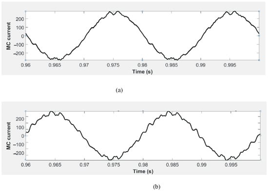
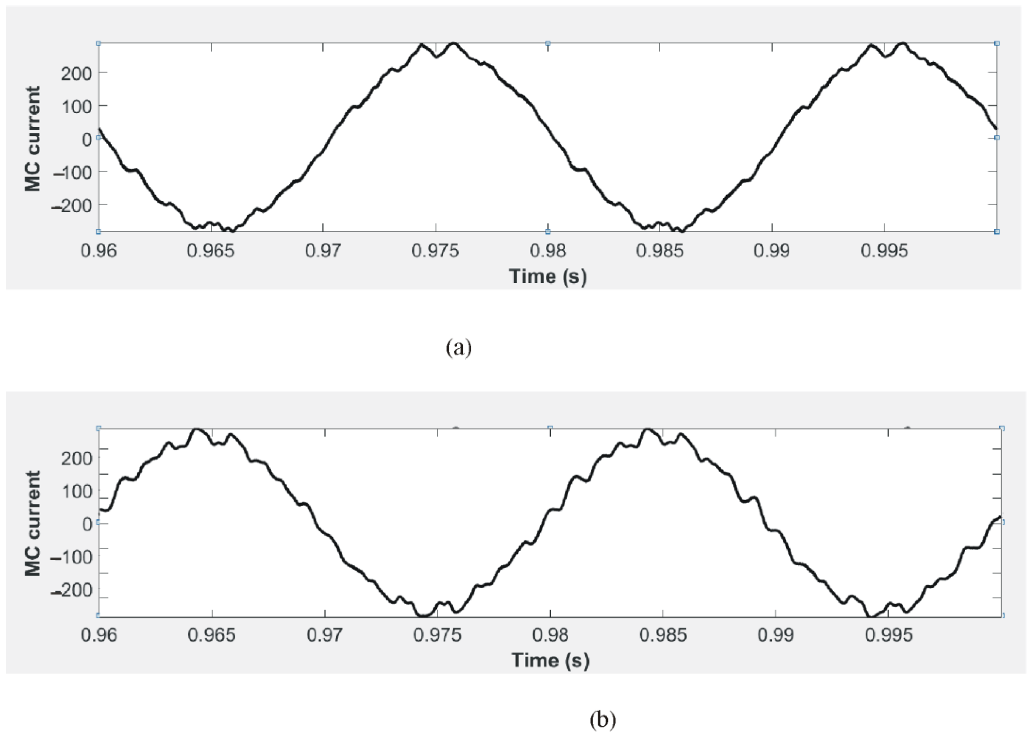
Figure 23.
The time course of the current of MC connection to utility grid point in the case of: (a) LC filter in power consumption mode; (b) LC filter in power supply mode.
In the case of LC filter use in the power consumption mode, THD IOutH and THD VR are close to the levels permitted by the standards. The voltage VR is maintained at normal level. The use of LC filter in the power consumption mode causes a significant drop in voltage VR—the CL filter interferes with MC. In the case of LC filter use in the power supply mode, THD IOutH and THD VR slightly exceeds the value allowed by the standards. The use of a two-branches filter allows the switching ripple harmonics to be suppressed to the level permitted by the standards. When the switching ripples are suppressed in the filter input current (Figure 23), the component of the filter resonant frequency (approximately 1000 Hz) becomes visible. The use of CL filter in the power consumption mode causes significant rise in voltage VR—the CL filter is a barrier to power transfer to the utility grid. The simulation results support the assumption that CL (as well as LCL) filters are not applicable for the bidirectionally operating MC.
6. Conclusions
In this study, the four base requirements that must be met by the filter applied for the switching ripple harmonics attenuation in the bidirectionally operating, utility grid connected MC, are formulated. These requirements are expressed in Equations (8)–(11). The verification for the suitability of the commonly used filters (L, LC and LCL), resonant filter, and two-branch filter according to these four requirements was performed.
Having evaluated the characteristics of the L filter, it has been found that the L filter does not meet the requirements for the bidirectional power flow. As a result, the L filter is considered to be not applicable for the bidirectionally operating MC.
After evaluating the characteristics of the LC filters, it is found that this filter meets the formulated requirements. In the case of a grid side inductor connection, the LC filter is considered to be applicable for the bidirectionally operating MC. If the capacitor is connected to the utility grid side, it is found that the CL filter does not meet the requirements for the bidirectional power flow. In this case, the CL filter is considered not applicable for the bidirectionally operating MC.
The LCL filter, which is most commonly used in renewable power plants connected to the utility grid via a voltage source inverter, does not meet the requirements of bidirectional power flow. Therefore, the LCL filter is considered to be not applicable for the bidirectionally operating MC.
The resonance filter meets the formulated requirements only by attenuating switching ripple harmonics with a very narrow spectrum of frequencies. Therefore, the resonant filter is considered to be not applicable for the bidirectionally operating MC.
Having evaluated the characteristics of the two-branch filter, it has been found that this filter meets the formulated requirements. Due to the higher number of elements than in the other filter topologies, this filter attenuates the switching ripple harmonics more efficiently. Therefore, the two branches filter is considered to be applicable for the bidirectionally operating MC.
The simulation results support the assumption that the LC filter and two branches’ filter is suitable for the bidirectionally operating MC both in power supply and power consumption modes. The simulation results show that voltage and current harmonic distortions are close to the levels permitted by the electrical code. The simulation also supports the assumption that CL (as well as LCL) filters are not applicable for the bidirectionally operating MC because the filters (as well as LCL) interfere with MC.
The simulation results showed a slight increase of THD in the renewable source current in power supply mode when the LC filter is connected. This must be taken into account in the calculation of component values for bidirectional filters.
7. Discussion
The results show that the theoretical assumptions regarding the suitability of the filter for a bidirectional energy flow controlling matrix converter are fully confirmed by Matlab/Simulink simulation. THD remains at a similar level at bidirectional energy flow. The results of the study also show that the possibilities to choose different types of filters at the point of the matrix converter connection to power grid are limited, because only two filter configurations can possibly be used—LC and two-branch filters. Therefore, a higher IGBT switching frequency needs to be used to increase the filter efficiency and reduce THD. Another way to reduce THD is to significantly increase the values of the filter elements, but this would have a negative impact in terms of size, weight and price. Therefore, reducing THD in systems with high-power matrix converters (double-fed induction generator for wind energy conversion system) becomes a challenging task because there are few means to improve filter efficiency without increasing filter parameters, dimensions and cost. In the light of these findings, it is appropriate to investigate the performance of filters consisting of more than two branches in further studies. Preliminarily, increasing the number of branches is a way to improve the efficiency of the filter without increasing its weight, size and cost. This is the subject of further research.
Author Contributions
Conceptualization, G.S.; methodology, G.S.; software, G.P.; validation, G.S. and G.P.; formal analysis, G.S.; investigation, G.P. and G.S.; resources, G.P. and G.S.; writing—original draft preparation, G.P.; writing—review and editing, G.S.; visualization, G.P.; funding acquisition, G.P. All authors have read and agreed to the published version of the manuscript.
Funding
This research was supported by the Lithuanian Agency for Science, Innovation and Technology (grant number MITA-T-851-01-0032).
Conflicts of Interest
The authors declare no conflict of interest.
Nomenclature
| Abbreviations | Value |
| CF | Filter capacitance |
| CFMAX | Maximum value of filter capacitance |
| fH | Frequency of special harmonic |
| fS | Utility grid frequency |
| fSW | Commutation frequency of MC |
| H1(jω) | Input impedance of filter |
| H2(jω) | Output current based transfer ratio of filter |
| H3(jω) | Output voltage based transfer ratio of filter |
| IH | Harmonic current of filterless MC |
| IMC | Current of the MC on grid frequency |
| IInH | Current of the harmonic at the filter input |
| IOutH | Current of the harmonic at the filter output |
| IR | Current of the renewable source of energy |
| LF | Inductivity of the filter component |
| LCB | Inductivity of the utility grid |
| LTR | Inductivity of the power transformer winding |
| PMC | Power of the MC |
| SMC | Total power of the MC |
| VH | Total harmonic voltage of filterless MC |
| VInH | Harmonics voltage of MC at input of the filter |
| VLF | Voltage of filter inductor |
| VR | Voltage of renewable element |
| VS | Utility grid voltage |
| ZGRID | Utility grid impedance |
| ZInF | Input impedance of the filter |
| ZRFIL | Series impedance of resonance filter |
| ωRes | Resonant frequency |
| QF | Reactive power of input filter capacitance |
References
- Tang, X.; Hu, Y.; Chen, Z.; You, G. Flexibility Evaluation Method of Power Systems with High Proportion Renewable Energy Based on Typical Operation Scenarios. Electronics 2020, 9, 627. [Google Scholar] [CrossRef]
- Szcześniak, P.; Kaniewski, J. Hybrid Transformer with Matrix Converter. IEEE Trans. Power Deliv. 2016, 31, 1388–1396. [Google Scholar] [CrossRef]
- Abdelrahem, M.; Hackl, C.; Kennel, R. Robust Predictive Control Scheme for Permanent-Magnet Synchronous Generators Based Modern Wind Turbines. Electronics 2021, 10, 1596. [Google Scholar] [CrossRef]
- Szczesniak, P.; Kaniewski, J. Power Electronics Converters without DC Energy Storage in the Future Electrical Power Network. Electr. Power Syst. Res. 2015, 129, 194–207. [Google Scholar] [CrossRef]
- Petrauskas, G.; Svinkunas, G. Application of Matrix VFD for Power Factor Improvement in LED Lighting Sources Loaded Power Distribution Lines. Energies 2021, 14, 3546. [Google Scholar] [CrossRef]
- Imam, A.A.; Kumar, R.S.; Al-Turki, Y.A. Modeling and Simulation of a PI Controlled Shunt Active Power Filter for Power Quality Enhancement Based on P-Q Theory. Electronics 2020, 9, 637. [Google Scholar] [CrossRef]
- Büyük, M.; Tan, A.; Tümay, M.; Bayındır, K.C. Topologies, Generalized Designs, Passive and Active Damping Methods of Switching Ripple Filters for Voltage Source Inverter: A Comprehensive Review. Renew. Sustain. Energy Rev. 2016, 62, 46–69. [Google Scholar] [CrossRef]
- Napole, C.; Barambones, O.; Derbeli, M.; Cortajarena, J.A.; Calvo, I.; Alkorta, P.; Bustamante, P.F. Double Fed Induction Generator Control Design Based on a Fuzzy Logic Controller for an Oscillating Water Column System. Energies 2021, 14, 3499. [Google Scholar] [CrossRef]
- Sikorski, A.; Falkowski, P.; Korzeniewski, M. Comparison of Two Power Converter Topologies in Wind Turbine System. Energies 2021, 14, 6574. [Google Scholar] [CrossRef]
- Rodarte Gutiérrez, F.E.; Carranza Castillo, O.; Rodríguez Rivas, J.J.; Ortega González, R.; Peralta Sánchez, E.; González Morales, L.G. Harmonics Reduction and Reactive Power Injection in Wind Generation Systems. Electronics 2021, 10, 1964. [Google Scholar] [CrossRef]
- Rodrigues, E.M.G.; Osório, G.J.; Godina, R.; Bizuayehu, A.W.; Lujano-Rojas, J.M.; Catalão, J.P.S. Grid code reinforcements for deeper renewable generation in insular energy systems. Renew. Sustain. Energy Rev. 2016, 53, 163–177. [Google Scholar] [CrossRef]
- Vasipalli, V.; Phulambrikar, S.P.; Agrawal, A. Power Quality Improvement in DFIG System with Matrix Converter in Wind Energy Generation with Space Vector Control Techniques. In Proceedings of the 2015 IEEE International Conference on Technological Advancements in Power and Energy, Kollam, India, 24–26 June 2015; IEEE: Piscataway, NJ, USA; pp. 73–78. [Google Scholar]
- Zhang, L.; Watthanasarn, C. A matrix converter excited doubly-fed induction machine as a wind power generator. In Proceedings of the 1998 Seventh IEEE International Conference on Power Electronics and Variable Speed Drives (IEE Conf. Publ. No. 456), London, UK, 21–23 September 1998; IEEE: Piscataway, NJ, USA; pp. 532–537. [Google Scholar]
- Gholami-Khesht, H.; Davari, P.; Blaabjerg, F. An Adaptive Model Predictive Voltage Control for LC-Filtered Voltage Source Inverters. Appl. Sci. 2021, 11, 704. [Google Scholar] [CrossRef]
- Lorzadeh, I.; Askarian Abyaneh, H.; Savaghebi, M.; Bakhshai, A.; Guerrero, J.M. Capacitor Current Feedback-Based Active Resonance Damping Strategies for Digitally-Controlled Inductive-Capacitive-Inductive-Filtered Grid-Connected Inverters. Energies 2016, 9, 642. [Google Scholar] [CrossRef] [Green Version]
- Ghasemi, M.A.; Zarei, S.F.; Peyghami, S.; Blaabjerg, F. A Theoretical Concept of Decoupled Current Control Scheme for Grid-Connected Inverter with L-C-L Filter. Appl. Sci. 2021, 11, 6256. [Google Scholar] [CrossRef]
- Trentin, A.; Zanchetta, P.; Clare, J.; Wheeler, P. Automated Optimal Design of Input Filters for Direct AC/AC Matrix Converters. IEEE Trans. Ind. Electron. 2012, 59, 2811–2823. [Google Scholar] [CrossRef]
- Wen, G.; Chen, Y.; Zhong, Z.; Kang, T. Dynamic Voltage and Current Assignment Strategies of Nine-Switch-Converter-Based DFIG Wind Power System for Low-Voltage Ride-Through (LVRT) Under Symmetrical Grid Voltage Dip. IEEE Trans. Ind. Appl. 2016, 52, 3422–3434. [Google Scholar] [CrossRef]
- Yang, S.; Zhou, T.; Sun, D.; Xie, Z.; Zhang, X. A SCR crowbar commutated with power converter for DFIG-based wind turbines. Int. J. Electr. Power 2016, 81, 87–103. [Google Scholar] [CrossRef]
- Song, Y.; Wang, X.; Blaabjerg, F. Doubly Fed Induction Generator System Resonance Active Damping through Stator Virtual Impedance. IEEE Trans. Ind. Electron. 2017, 64, 125–137. [Google Scholar] [CrossRef]
- Wheeler, P.; Grant, D. Optimized input filter design and low-loss switching techniques for a practical matrix converter. IEEE Proc. -Electr. Power Appl. 1997, 144, 53–60. [Google Scholar] [CrossRef]
Publisher’s Note: MDPI stays neutral with regard to jurisdictional claims in published maps and institutional affiliations. |
© 2021 by the authors. Licensee MDPI, Basel, Switzerland. This article is an open access article distributed under the terms and conditions of the Creative Commons Attribution (CC BY) license (https://creativecommons.org/licenses/by/4.0/).