Article

The Influence of Design on Electrical Performance of AlGaN/GaN Lateral Schottky Barrier Diodes for Energy-Efficient Power Applications

Integrated Optics and Microwave Photonics Laboratory, Tomsk State University of Control System and Radioelectronics, 634050 Tomsk, Russia
*
Author to whom correspondence should be addressed.
Electronics 2021, 10(22), 2802; https://doi.org/10.3390/electronics10222802
Submission received: 30 September 2021 / Revised: 10 November 2021 / Accepted: 12 November 2021 / Published: 15 November 2021
(This article belongs to the Section Power Electronics)

Abstract

:
In this paper, lateral AlGaN/GaN Schottky barrier diodes are investigated in terms of anode construction and diode structure. An original GaN Schottky diode manufacturing-process flow was developed. A set of experiments was carried out to verify dependences between electrical parameters of the diode, such as reverse and forward currents, ON-state voltage, forward voltage and capacitance, anode-to-cathode distance, length of field plate, anode length, Schottky contact material, subanode recess depth, and epitaxial structure type. It was found that diodes of SiN/Al0.23Ga0.77N/GaN epi structure with Ni-based anodes demonstrated two orders of magnitude lower reverse currents than diodes with GaN/Al0.25Ga0.75N/GaN epitaxial structure. Diodes with Ni-based anodes demonstrated lower VON and higher IF compared with diodes with Pt-based anodes. As a result of these investigations, an optimal set of parameters was selected, providing the following electrical characteristics: VON = 0.6 (at IF = 1 mA/mm), forward voltage of the diode VF = 1.6 V (at IF = 100 mA/mm), maximum reverse voltage VR = 300 V, reverse leakage current IR = 0.04 μA/mm (at VR = −200 V), and total capacitance C = 3.6 pF/mm (at f = 1 MHz and 0 V DC bias). Obtained electrical characteristics of the lateral Schottky barrier diode demonstrate great potential for use in energy-efficient power applications, such as 5G multiband and multistandard wireless base stations.

1. Introduction

Microwave photonics is a new, scientific, technical and technological direction, which appeared as a result of the integration of optoelectronics and microwave radioelectronics. The high frequency of the optical carrier (about 1015 Hz), the huge bandwidth of optical systems (more than 10 THz), the low losses in optical waveguides (less than 0.15 dB/km) [1], as well as immunity to radio-frequency interference provide an effective solution a wide range of problems in modern ultrawideband systems as part of telecommunications and radar complexes, including the construction of high-speed fiber-optic and wireless communication systems (5G, HDWDM) [2,3]. Technology acceleration has driven infrastructural hardware to be more compact, easier to integrate, and more economic, while offering smarter and more multifunctional characteristics. There has emerged a necessity for ultracompact, ultrawideband, multi-input-multi-output antennas—metamaterial transmission-line based antenna systems [4,5]. Hence, a lot of effort has been invested over the past several years in developing wideband antennas that meet the requirements of 5G systems and support other multiband and multistandard wireless systems [6,7]. The transition to fifth-generation networks also places serious demands on the infrastructure; it is required to install five times more base stations per square kilometer, each of which consumes an average of 1.1 kW [8]. All this makes for serious demands on the energy efficiency of all engineering systems, including power systems. This is driving market demand and creating a need for new solutions to reduce power consumption. In recent years, gallium nitride devices have become promising candidates for power electronic applications. A heterojunction at the AlGaN/GaN interface gives gallium nitride devices enormous advantages over their Si and SiC counterparts [9,10]. The high concentration of carriers and their high mobility make it possible to use the heterojunction as a channel layer with an extremely low resistivity, which ensures the flow of currents with an extremely high density in the channel of GaN devices [11,12]. The wide band gap allows GaN devices to operate at higher operating temperatures and faster switching speeds with less power loss [13,14].
Many results of design and production of GaN Schottky barrier diodes (SBDs) have been presented [15,16,17,18,19,20,21,22,23,24,25,26,27,28]. Some research has been focused on CMOS fabs [15,16,17] and other research has focused on RF fabs [18,19,20,21,22,23,24,25,26,27,28]. To date, quite a lot of design features have been reported regarding SBDs, and most of reported results have used field plates for efficient electric field redistribution between anode and cathode, and increasing the diode’s breakdown voltage (VBR) [16]; increasing anode-to-cathode distance leads to an increase in the diode’s resistance in the ON-state (RON) and VBR [29]. Tt is also a known fact that subanode recess is mandatory to create an SBD with low reverse leakage current (IR) and low threshold voltage (VON) [15,16,18,19]. Despite this, there are some claims reported which bring some uncertainty, such as regarding the depth of subanode recess and material of the cap layer. In works [18,19], Pt was used as the Schottky barrier metal, which resulted in VON = 0.43–0.7 V and reverse current around IR = 10−10 A/mm at VR = −200 V. In works [15,16,17,20,21,22,23], Ni was used as the Schottky barrier metal, which resulted in VON = 0.37–0.5 V and reverse current around IR = 10−6 A/mm at VR = −200 V. In [30], authors reported on the performance of dual-barrier InAlN/AlGaN/GaN HEMTS on silicon substrates with Pt- and Ni-based gates. Authors reported that Pt-based gates showed an overall improvement in gate leakage by 2–3 orders of magnitude. The difference of ~0.5 eV in work function between Pt and Ni led to a larger surface Schottky barrier height and a resulting lower channel 2DEG density under the gate if Pt is used. In [13,14,15,16], authors used TiN as the Schottky metal to make the process flow compatible with the CMOS process. TiN-based Schottky contact provided VON = 0.41 V and reverse current around IR = 10−6 A/mm at VR = −200 V [15]. Despite the fact that all the solutions are considered to be reliable and working, there is no clear understanding of which SC material would provide lower VON, Ir and Ron of a diode manufactured on RF fab. In works [15,16,17,20], authors claimed that a 5 nm-thickness AlGaN barrier layer was most optimal subanode recess depth, while in works [18,19,21,22,23], the authors claim that overetching of the barrier layer is the most optimal subanode recess. In work [24], SBDs with SiN as the cap layer demonstrated 15 times lower reverse leakage currents compared with samples with a GaN+SiN cap layer. In works [15,16,17,20,21,22,23], authors use epitaxial structures with GaN as the cap layer, while in [19], in situ SiN is used as the cap layer. To our knowledge, no direct comparison of SiN and GaN caps on the electrical performance of GaN SBDs has been carried out so far.
The work purposes the approbation of previously reported dependencies between SBD design and its electrical parameters on epitaxial structures and SBDs of original design, proposed in this work.

2. Materials and Methods

The GaN-based SBDs were manufactured on commercial AlGaN/GaN epitaxial structures on SiC wafer grown by Enkris Semiconductor [31]. In this research, two types of epitaxial structures with different barrier and cap layers were used. Both types of structures were grown on 500 μm 4H-SiC wafer. Epitaxial layers consist of 1.1 μm Fe-doped GaN buffer, a 400 nm i-GaN channel, and a 0.8 nm AlN spacer. The first structure had a 22 nm Al0.23Ga0.77N barrier and a 5 nm SiN cap layer. The second structure had a 20 nm Al0.25Ga0.75N barrier and a 2 nm GaN cap layer. The epitaxial structure is schematically shown in Figure 1a. The first structure has a sheet resistance of 275 Ω/□, electron mobility of 2150 cm/V∙s and electron density of 1.05 × 1013 cm−2. The second structure had sheet resistance 305 Ω/□, electron mobility of 2100 cm/V∙s and electron density of 9.75 × 1012 cm−2. The AlGaN/GaN lateral SBD manufacturing-process flow is shown in Figure 1. The fabrication started with defining mesa isolation by reactive ion etching (RIE), the structure of the diode at this stage is shown in Figure 1b. A 15 nm recess for ohmic contacts has been formed in the barrier layer with a low-damage RIE process. Then, Ti/Al/Ni/Au-based (20/120/55/45 nm) cathode ohmic contacts were e-beam evaporated and annealed at 790 °C for 30 s in a nitrogen environment. The 100 nm PECVD SiNx film was deposited at 300 °C. At this stage, the structure cross-section looks as shown in Figure 1c. A trench for the anode Schottky contacts was defined by lithography and subsequent RIE in low damage BCl3/O2 plasma. For the first structure, the in situ SiN cap was etched by SF6 plasma previously before recess etching. The anode recess in the AlGaN barrier layer had values of hrecess 0 nm (100% of the barrier thickness), 15 nm (25% of the barrier thickness) and 40 nm (overetched barrier). Figure 1d shows diode structure cross-section at this stage. Ni/Au (30/400 nm) and Pt/Ti/Au (30/20/400 nm) Schottky contacts were formed by the e-beam evaporation technique (Figure 1e). The second layer of passivation was formed with 100 nm SiNx PECVD film. Next, metal stack M1, consisting of Ti/Pt/Au (30/25/400 nm), was formed by the e-beam evaporation technique with subsequent SiNx surface passivation (shown in Figure 1f). After that, M1 was gold plated with second metal stack M2, consisting of Ti/Au/Ti/Au (20/150/20/5000 nm) to reduce metallization resistance. Finally, the surface was passivated with 170 nm ICP SiNx film. The final diode structure is schematically shown in the cross-section in Figure 1g.
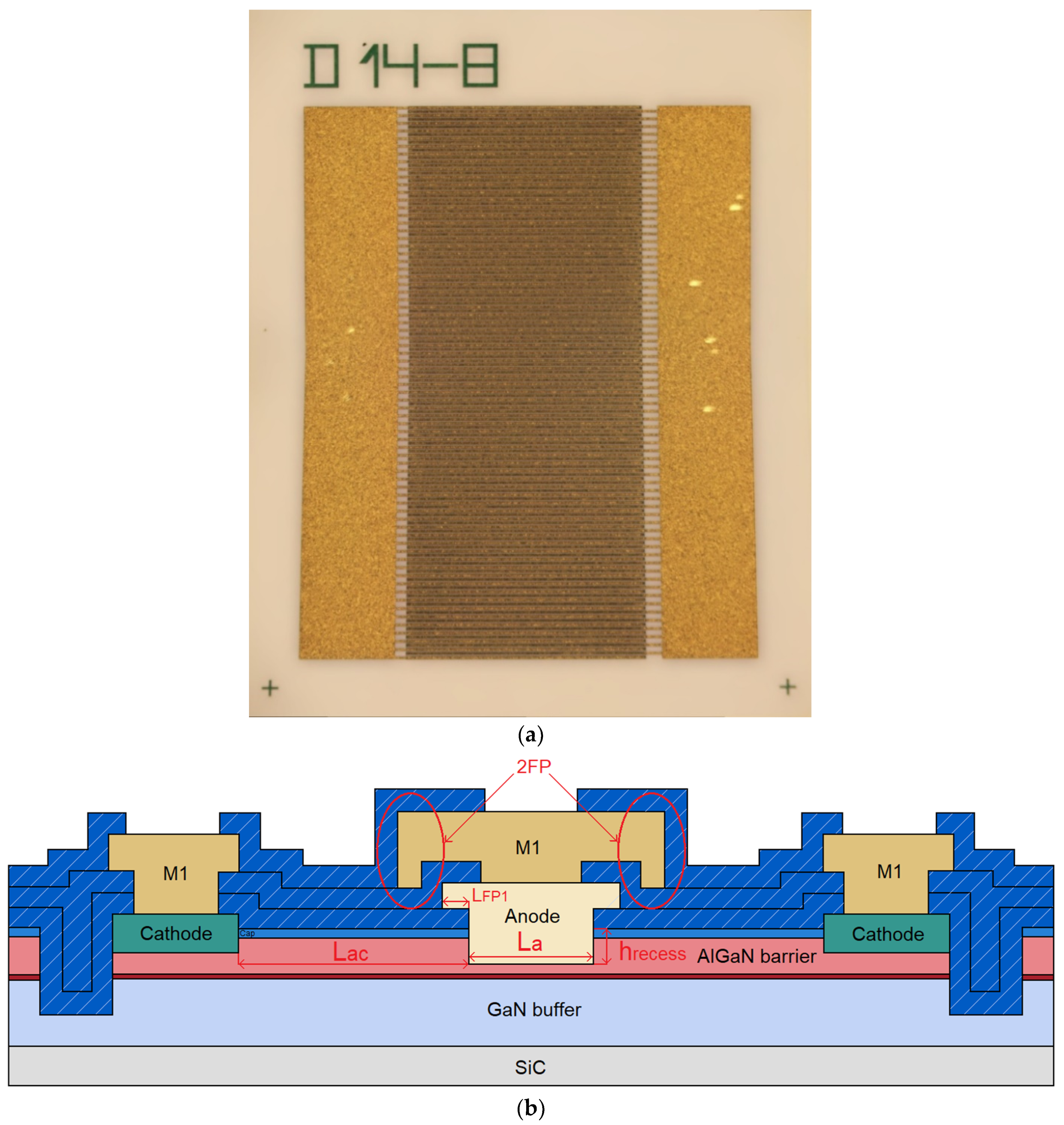
Figure 2a shows microscopic image of diode with total anode width W = 60 mm, fabricated using the process flow described above. Figure 2b shows cross-sectional schematics of an SBD with two field plates with the first metal stack, M1. Wafer topology included a wide range of diode structures with different widths, W, ranging from 100 μm to 100 mm; anode-to-cathode distance LAC ranging from 4 to 9 μm; first field-plate length LFP1 ranging from 1 to 3.5 μm; anode length LA equal to 6 and 11 μm, and second field plate (2FP) in M2 metal stack (shown in Figure 2b).
The I-V characteristics of fabricated rectifiers were measured using HP4156A. Breakdown characteristics were measured on an L2-56 semiconductor parameter analyzer. C-V characteristics were measured with Agilent E4980A. Size and diode appearance were controlled using optical microscopy. The following electrical characteristics of fabricated diodes were studied: forward current IF, reverse current IR, diode turn-on voltage VON, diode forward voltage drop VF, diode capacitance C, diode reverse breakdown voltage VBR and diode on-state resistance RON. IF was measured at VF = 1.4 V; IR was measured at VR = −200 V; VON was defined at 1 mA/mm forward current density; VF was defined at 100 mA/mm forward current density; C was measured at frequency f = 1 MHz and 0 V bias; VBR was defined as reverse DC voltage at IR = 1 mA/mm.

3. Results and Discussion

Experiments were carried out in two stages. In the first stage, anode structure influence on electrical parameters of AlGaN/GaN lateral SBD was investigated. During this series of experiments LAC, LFP1, LA and 2FP were altered, with assessment of their influence on IF, IR, VON, VF and C. As a result of these experiments, optimal anode structure was determined. In the second stage, diode structure analysis was carried out. During this series of experiments, the influence of Schottky contact (SC) material, depth of subanode recess and epitaxial structure influence on electrical parameters of SBDs were evaluated. As a result of these investigations, the optimal combination of parameters could be proposed.
The influence of LAC on IF, IR and VBR on SBDs is shown in Figure 3a. For convenient and fair comparison of IF, IR and VBR, several hundred diodes’ average values were calculated and then normalized in the range of 0 to 1 as the ratio of the current value of a series to the maximum value in this series. It was found that an increase in the LAC in the range of 4 to 9 μm leads to a decrease in the forward and reverse currents of the diode, which could be explained by a change in the resistance of the active area. At the same time, reducing LAC from 9 to 4 μm leads to decrease in breakdown voltage. In range from 7 to 9 μm, LAC does not affect the value of breakdown voltage, probably because breakdown occurs through the buffer layer (which is not optimized for high-voltage operation). Further decrease in LAC led to a considerable reduction in VBR. According to the demonstrated dependence, the optimal value of anode-to-cathode distance is 7 μm, as a compromise between high breakdown voltage and IF and low IR. This LAC is sufficient to achieve peak diode reverse voltage 300 V. The obtained dependence is in complete agreement with results, earlier reported in [17,18,20,23,29].
The normalized average results of LFP1 influence on IF, IR and C of SBDs, which were calculated the same way as above, are shown in Figure 3b. It was found that an increase in LFP1 in the range 1 μm to 3.5 μm leads to a decrease in the reverse currents of the diode. A field plate is usually added for redistribution of the electric field strength in the diode, which probably, in our particular case, resulted in improved control of the channel current and reduced reverse leakage currents. Changing LFP1 did not had any significant impact on diode forward current. Increasing the length of the field plate leads to increase in diode capacitance, which affects the frequency characteristics of diode. According to obtained dependencies, it could be claimed that the optimal value of LFP1 length is 2 μm, as a compromise between the values of IR and C in the GaN diode.
Table 1 summarizes results of investigations on the influence of the presence of a second field plate (2FP) and anode length LA on ID, IR, C. GaN diodes with 2 μm-long 2FP demonstrated 25% lower reverse current IR and a 20% increase in capacitance C compared with diodes without 2FP.
As a result of the investigation on the effect of the anode length, it was found that an increase in the LA from 6 to 11 μm leads to a decrease in the reverse current of the diode on 17%, and a slight increase in the capacitance of the diode from 3.63 pF/mm to 3.34 pF/mm.
Based on the results of anode structure analysis, the optimal anode design, which has LAC = 7 μm, LFP1 = 2 μm, LA = 11 μm, LFP2 = 2 μm, is proposed for further investigations. The presented anode design allows for obtaining minimal reverse currents IR at maximum forward currents IF and low capacitance C. Further investigation into subanode recess, epitaxial structure and Schottky barrier metal was carried out with use of these diodes.
Table 2 presents the results of a comparison between two structures in terms of forward and reverse currents. As a result of the investigation into the effect of epitaxial structure, it was found that diodes with a Pt-based Schottky barrier have 2–4 orders of magnitude lower reverse currents, IR, on the first epitaxial structure compared with the second structure. Diodes with Ni-based Schottky contact on the second epitaxial structure had lower IR and IF, which is possibly due to a lower molar fraction of aluminum in the AlGaN.
Figure 4 summarizes the results of the investigation into the effect of SC material on electrical parameters of diodes. As shown in Figure 4a, it was revealed that the Ni-based SC provides 53–70% higher forward currents compared with Pt-based SC. The summary of measurements of IR is presented in Figure 4b. One can observe that Ni-based SC on structure two provides 7.5 times lower reverse currents than the Pt-based SC, while samples on structure one and Pt-based SC with different subanode recess depths demonstrated 2–3 orders of magnitude lower leakage current than samples with Ni-based SC. The Ni-based SC has a lower VON value than the Pt-based SC due to the lower Schottky barrier, which is in complete agreement with reported barrier heights [32]. The observed effects are in good agreement with results reported in [30].
Figure 5 summarizes the results of the investigation into subanode recess depth on electrical parameters of the diode. As a result of this investigation, it was found that samples with Ni-based SC, on structure one, and without subanode recess, demonstrate the worst parameters of all samples investigated: IR = 115 μA/mm, IF = 3.14 mA/mm, VON = 1.55 V and VF = 3.22 V. As shown in Figure 5a,b, increasing recess etching depth from 0 to 40 nm led to an increase in the forward current IF of the diode by 50 times, and to a 1.5 times decrease in the reverse current IR.
An increase in the recess depth from 15 to 40 nm for samples based on a structure of type one and a Pt-based SC led to a decrease in the reverse current by an order of magnitude, which is possibly associated with the different Schottky barrier height between the Pt/Al0.23Ga0.78N contact (0.94 eV) and Pt/GaN contact (1.55 eV). An increase in the recess depth for samples based on structures of type two and Pt SC lead to a decrease in VON.
As a result of the investigation carried out, an optimal set of diode construction features was identified, as well as general dependences between design features and electrical parameters. The obtained dependences partially agree with the results presented in other works, in which the diodes were manufactured on CMOS fabs [15,16] and RF fabs [18,19,20,21,22,23,24,25,26,27,28]. Particularly, a decrease in reverse currents and an increase in forward currents with an increase in the depth of the subanode recess on structures with Ni SC was observed, as was the case in [22]. An increase in the distance between the anode and cathode led to a decrease in the forward and reverse currents of the diode, as was the case in other works [22]. All of the diodes with LAC = 7 and 8 μm demonstrated a breakdown voltage around 320 V, which is due to the breakdown through the buffer layer, but not between the anode and cathode. Modifying the GaN buffer layer (increase the thickness and doping) could increase reverse breakdown voltage and reduce reverse currents of SBDs.
The results of the experiment demonstrate that experimental samples on structure two had higher reverse currents than samples on structure one. At the same time, samples on structure one demonstrated higher forward currents and lower VON and VF. For a qualitative assessment of the obtained diodes, among all the samples, the one that would provide the best combination of electrical parameters was chosen. Optimal SBDs were fabricated on the epitaxial structure of type one (Al0.23Ga0.77N barrier, SiN cap) with overetched anode recess and Pt-based Schottky barrier. The diode had an 11 μm-long anode, two field plates (LFP1 = 2 μm, LFP2 = 2 μm), anode–cathode distance of 7 μm and total anode width of 60 mm. Diodes in the described embodiment demonstrate the following characteristics: ON-state voltage VON = 0.6 V (at IF = 1 mA/mm), forward current of the diode IF = 60 mA/mm (at V = 1.4 V), maximum reverse voltage VBR = 300 V, reverse leakage current IR = 0.04 μA/mm (at VR = -200 V), and capacitance C = 3.6 pF/mm (at f = 1 MHz and 0 V DC bias).
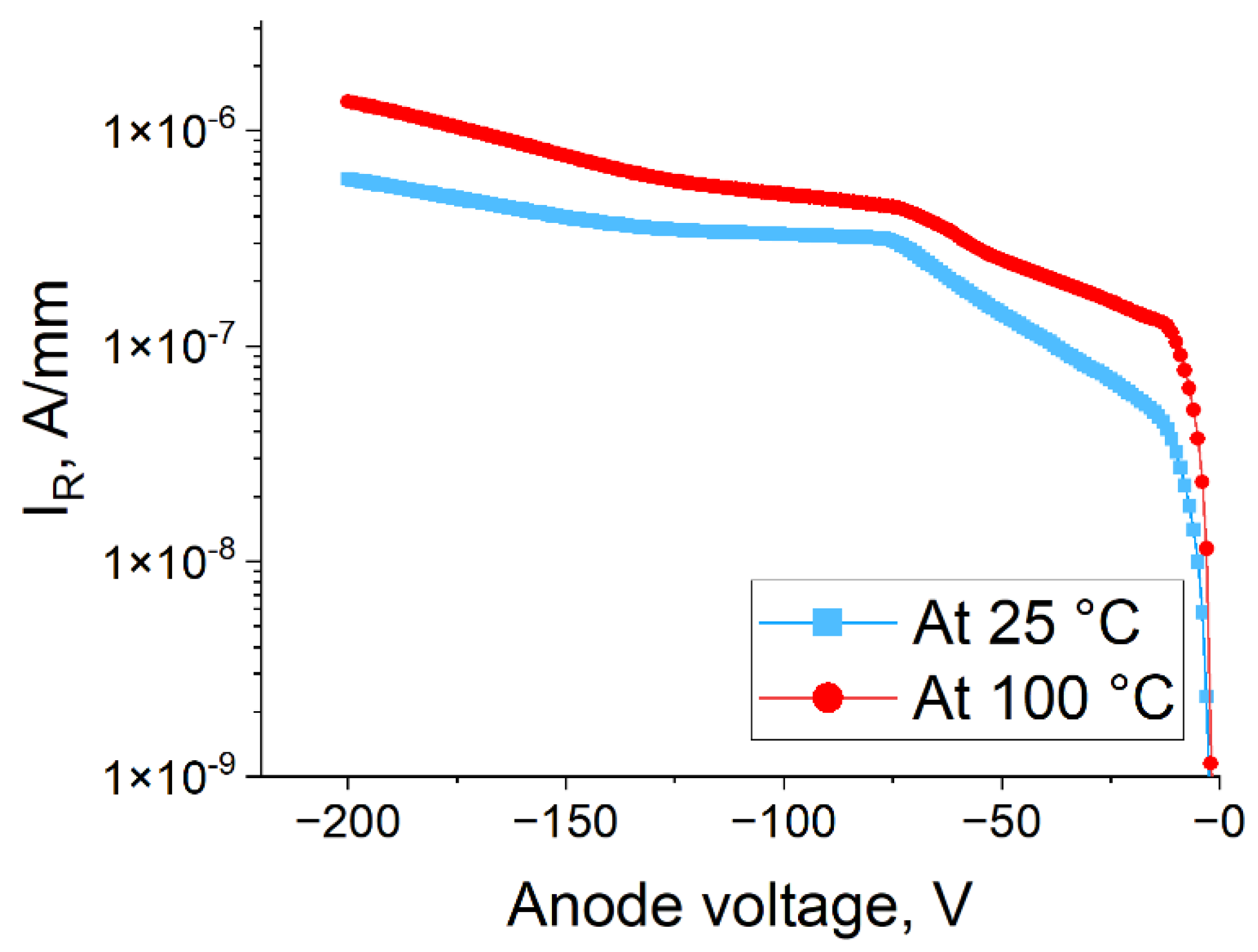
The thermal stability of the leakage current of fabricated SBDs with optimal construction was investigated. The results are represented in Figure 6. The I-V measurements were carried out at 25 and 100 °C. As a result, it was found out that fabricated SBDs demonstrate a ~2.3 times increase in leakage currents with a 75 °C operation temperature shift. Table 3 shows the comparison of different lateral AlGaN/GaN SBDs.
Table 3 shows the comparison of different lateral AlGaN/GaN SBDs. The manufactured diodes demonstrate the forward voltage VF = 1.6 V, threshold voltage VON = 0.6 V and low reverse current IR = 0.04 μA/mm, which shows competitive performance over most reported data. It is obvious that the diodes manufactured in this work demonstrate relatively low breakdown voltage compared to previously reported results. This is due to the rather thin buffer layer (1.1 μm) used, which is more useful for RF, rather than power applications. An increase in the buffer thickness would lead to higher breakdown voltages and a lower leakage current. Diodes could be used as rectifiers in power conversion circuits of high efficiency for fifth-generation communication systems and microwave photonics.

4. Conclusions

In conclusion, the influence of design on the electrical characteristics of AlGaN/GaN lateral Schottky barrier diodes was investigated. It was found that diodes with SiN/Al0.23Ga0.77N/GaN epitaxial structures and Ni-based SC demonstrate, by two orders of magnitude, lower reverse currents than diodes with GaN/Al0.25Ga0.75N/GaN epitaxial structures. SBDs with Ni-based SC demonstrate lower VON and higher IF compared to those with Pt-based SC. It was found that subanode recess is mandatory for manufacturing SBDs with low IR, VON and VF. An overetched barrier layer in the anode region of diodes with Pt SC resulted in low IR = 0.04 μA/mm.
As a result, GaN lateral Schottky barrier diodes with Pt-based SC and SiN/Al0.23Ga0.77N/GaN (5/22/400 nm) epitaxial structure with overetched anode recess (40 nm) were fabricated. The diodes had an anode width of WA = 60 mm and length of LA = 11 μm, and anode-to-cathode distance LAC = 7 μm. The diodes demonstrated the following electrical characteristics: ON-state voltage VON = 0.6 V, forward current IF = 4 A, maximum reverse voltage VR = 300 V, forward voltage drop VF = 1.6 V, reverse current IR = 2.4 μA and total capacitance C = 216 pF (at 0 V, T = 25 °C, f = 1 MHz).

Author Contributions

Conceptualization, E.E.; methodology, E.E. and E.P.; software, E.P.; validation, E.E., E.P. and I.Y.; formal analysis, I.Y.; investigation, E.P.; resources, E.E.; data curation, E.P.; writing—original draft preparation, E.P. and E.E.; writing—review and editing, E.E. and I.Y.; visualization, I.Y.; supervision, I.Y.; project administration, E.E.; funding acquisition, E.E. All authors have read and agreed to the published version of the manuscript.

Funding

The work was carried out with financial support from the Ministry of Science and Higher Education of the Russian Federation (Project name: Theoretical and experimental studies of ultra-wideband optoelectronic devices of fiber-optic information systems and radiophotonics based on photonic integrated circuits own development, Agreement No. 075-03-2020-237/1 from 5 March 2020, project number: FEWM-2020-0040) and Project No. AAAA-A20-120070390024-2. Experimental results were obtained by the team of the Integrated Optics and Radiophotonics Laboratory of the Tomsk State University of Control Systems and Radioelectronics using equipment of the “Impulse” center of collective usage (registration number 200568).

Acknowledgments

The authors of this study express their appreciation to the staff of the “Nanotechnology” Education & Research Center, TUSUR University, and of the “Microelectronics” Research & Production Department, Micran Research & Production Company, for their involvement and assistance in the work.

Conflicts of Interest

The authors declare no conflict of interest.

References

  1. Tamura, Y.; Sakuma, H.; Morita, K.; Suzuki, M.; Yamamoto, Y.; Shimada, K.; Honma, Y.; Sohma, K.; Fujii, T.; Hasegawa, T. The first 0.14-dB/km loss optical fiber and its impact on submarine transmission. J. Light. Technol. 2018, 36, 44–49. [Google Scholar] [CrossRef]
  2. Erofeev, E.; Arykov, V.; Stepanenko, M.; Voevodin, A.; Kogai, A.; Kurikalov, V.J.S. 28 GHz Single-Chip Transmit RF Front-End MMIC for Multichannel 5G Wireless Communications. Symmetry 2020, 12, 1167. [Google Scholar] [CrossRef]
  3. Skubic, B.; Bottari, G.; Öhlén, P.; Cavaliere, F. The role of DWDM for 5G transport. In Proceedings of the 2014 The European Conference on Optical Communication (ECOC), Cannes, France, 21–25 September 2014; pp. 1–3. [Google Scholar]
  4. Alibakhshikenari, M.; Virdee, B.S.; See, C.; Shukla, P.; Moghaddam, S.M.; Zaman, A.U.; Shafqaat, S.; Akinsolu, M.O.; Liu, B.; Yang, J.; et al. Dual-polarized highly folded Bowtie antenna with slotted self-grounded structure for sub 6 GHz 5G applications. IEEE Trans. Antennas Propag. 2021, 1, 1–6. [Google Scholar] [CrossRef]
  5. Alibakhshikenari, M.; Virdee, B.S.; Azpilicueta, L.; Naser-Moghadasi, M.; Akinsolu, M.O.; See, C.H.; Liu, B.; Abd-Alhameed, R.A.; Falcone, F.; Huynen, I. A comprehensive survey of “metamaterial transmission-line based antennas: Design, challenges, and applications”. IEEE Access 2020, 8, 144778–144808. [Google Scholar] [CrossRef]
  6. Alibakhshikenari, M.; Babaeian, F.; Virdee, B.S.; Aïssa, S.; Azpilicueta, L.; See, C.H.; Althuwayb, A.A.; Huynen, I.; Abd-Alhameed, R.A.; Falcone, F. A comprehensive survey on “Various decoupling mechanisms with focus on metamaterial and metasurface principles applicable to SAR and MIMO antenna systems”. IEEE Access 2020, 8, 192965–193004. [Google Scholar] [CrossRef]
  7. Althuwayb, A.A.J.M.; Letters, O.T. Enhanced radiation gain and efficiency of a metamaterial-inspired wideband microstrip antenna using substrate integrated waveguide technology for sub-6 GHz wireless communication systems. Microwave Opt. Tech. Let. 2021, 63, 1892–1898. [Google Scholar] [CrossRef]
  8. Inamdar, M.A.; Kumaraswamy, H. Energy efficient 5G networks: Techniques and challenges. In Proceedings of the 2020 International Conference on Smart Electronics and Communication (ICOSEC), Tiruchirappalli, India, 10–12 September 2020; pp. 1317–1322. [Google Scholar]
  9. Roccaforte, F.; Fiorenza, P.; Greco, G.; Nigro, R.L.; Giannazzo, F.; Iucolano, F.; Saggio, M.J.M.E. Emerging trends in wide band gap semiconductors (SiC and GaN) technology for power devices. Microelectron. Eng. 2018, 187, 66–77. [Google Scholar] [CrossRef]
  10. Chowdhury, S.; Stum, Z.; Li, Z.D.; Ueno, K.; Chow, T.P. Comparison of 600V Si, SiC and GaN power devices. Mater. Sci. Forum 2014, 778–780, 971–974. [Google Scholar] [CrossRef]
  11. Hashizume, T.; Ootomo, S.; Oyama, S.; Konishi, M.; Hasegawa, H. Chemistry and electrical properties of surfaces of GaN and GaN/AlGaN heterostructures. J. Vac. Sci. Tech. Microelectron. Nanometer Struct. Process. Meas. Phenom. 2001, 19, 1675–1681. [Google Scholar] [CrossRef] [Green Version]
  12. Ambacher, O.; Smart, J.; Shealy, J.; Weimann, N.; Chu, K.; Murphy, M.; Schaff, W.; Eastman, L.; Dimitrov, R.; Wittmer, L. Two-dimensional electron gases induced by spontaneous and piezoelectric polarization charges in N-and Ga-face AlGaN/GaN heterostructures. J. Appl. Phys. 1999, 85, 3222–3233. [Google Scholar] [CrossRef] [Green Version]
  13. Chow, T.P.; Tyagi, R. Wide bandgap compound semiconductors for superior high-voltage power devices. In Proceedings of the 5th International Symposium on Power Semiconductor Devices and ICs, Monterey, CA, USA, 18–20 May 1993; pp. 84–88. [Google Scholar]
  14. Wu, Y.-F.; Kapolnek, D.; Ibbetson, J.P.; Parikh, P.; Keller, B.P.; Mishra, U. Very-high power density AlGaN/GaN HEMTs. IEEE Trans. Electron Devices 2001, 48, 586–590. [Google Scholar]
  15. Lenci, S.; De Jaeger, B.; Carbonell, L.; Hu, J.; Mannaert, G.; Wellekens, D.; You, S.; Bakeroot, B.; Decoutere, S.J.I.E.D.L. Au-free AlGaN/GaN power diode on 8-in Si substrate with gated edge termination. IEEE Electron Device Lett. 2013, 34, 1035–1037. [Google Scholar] [CrossRef]
  16. Hu, J.; Stoffels, S.; Lenci, S.; Bakeroot, B.; De Jaeger, B.; Van Hove, M.; Ronchi, N.; Venegas, R.; Liang, H.; Zhao, M. Performance optimization of Au-free lateral AlGaN/GaN Schottky barrier diode with gated edge termination on 200-mm silicon substrate. IEEE Trans. Electron Devices 2016, 63, 997–1004. [Google Scholar] [CrossRef]
  17. Zhou, Q.; Jin, Y.; Shi, Y.; Mou, J.; Bao, X.; Chen, B.; Zhang, B. High reverse blocking and low onset voltage AlGaN/GaN-on-Si lateral power diode with MIS-gated hybrid anode. IEEE Electron. Device Lett. 2015, 36, 660–662. [Google Scholar] [CrossRef]
  18. Bahat-Treidel, E.; Hilt, O.; Zhytnytska, R.; Wentzel, A.; Meliani, C.; Wurfl, J.; Trankle, G.J.I.E.D.L. Fast-switching GaN-based lateral power Schottky barrier diodes with low onset voltage and strong reverse blocking. IEEE Electron. Device Lett. 2012, 33, 357–359. [Google Scholar] [CrossRef]
  19. Treidel, E.B.; Hilt, O.; Wentzel, A.; Würfl, J.; Tränkle, G. Fast GaN based Schottky diodes on Si (111) substrate with low onset voltage and strong reverse blocking. Phys. Status Solidi 2013, 10, 849–852. [Google Scholar] [CrossRef]
  20. Lee, J.-G.; Park, B.-R.; Cho, C.-H.; Seo, K.-S.; Cha, H.-Y. Low turn-on voltage AlGaN/GaN-on-Si rectifier with gated ohmic anode. IEEE Electron. Device Lett. 2013, 34, 214–216. [Google Scholar] [CrossRef]
  21. Matioli, E.; Lu, B.; Palacios, T. Ultralow leakage current AlGaN/GaN Schottky diodes with 3-D anode structure. IEEE Trans. Electron Devices 2013, 60, 3365–3370. [Google Scholar] [CrossRef]
  22. Hsueh, K.-P.; Peng, L.-Y.; Cheng, Y.-H.; Wang, H.-Y.; Wang, H.-C.; Kao, H.-L.; Chiu, H.-C. Improved reverse recovery characteristics of low turn-on voltage AlGaN/GaN Schottky barrier diodes with anode edge AlON spacers. J. Alloys Compd. 2017, 703, 204–209. [Google Scholar] [CrossRef]
  23. Gao, J.; Jin, Y.; Xie, B.; Wen, C.P.; Hao, Y.; Shen, B.; Wang, M. Low ON-Resistance GaN Schottky Barrier Diode with High VON Uniformity Using LPCVD Si3N4 Compatible Self-Terminated, Low Damage Anode Recess Technology. Mater. Sci. Biol. 2018, 39, 859–862. [Google Scholar]
  24. Charles, M.; Baines, Y.; Bouis, R.; Papon, A. The characterization and optimization of GaN cap layers and SiN cap layers on AlGaN/GaN HEMT structures grown on 200 mm GaN on silicon. Phys. Status Solid 2018, 255, 1700406. [Google Scholar] [CrossRef]
  25. Zhang, T.; Zhang, J.; Zhang, W.; Zhang, Y.; Duan, X.; Ning, J.; Hao, Y. Investigation of an AlGaN-channel Schottky barrier diode on a silicon substrate with a molybdenum anode. Semicond. Sci. Technol. 2021, 36, 044003. [Google Scholar] [CrossRef]
  26. Basler, M.; Reiner, R.; Moench, S.; Waltereit, P.; Quay, R.; Kallfass, I.; Ambacher, O. Large-area lateral AlGaN/GaN-on-Si field-effect rectifier with low turn-on voltage. IEEE Electron. Device Lett. 2020, 41, 993–996. [Google Scholar] [CrossRef]
  27. Kang, X.; Zheng, Y.; Wu, H.; Wei, K.; Sun, Y.; Zhang, G.; Liu, X. Thin barrier gated-edge termination AlGaN/GaN Schottky-barrier-diode with low reverse leakage and high turn-on uniformity. Semicond. Sci. Tech. 2021, 36, 094001. [Google Scholar] [CrossRef]
  28. Soni, A.; Amogh, K.; Shrivastava, M. Design guidelines and performance tradeoffs in recessed AlGaN/GaN Schottky barrier diodes. IEEE Trans. Electron Devices 2020, 67, 4834–4841. [Google Scholar] [CrossRef]
  29. Tomita, R.; Ueda, S.; Kawada, T.; Mitsuzono, H.; Horio, K. Analysis of Dependence of Breakdown Voltage on Gate–Drain Distance in AlGaN/GaN HEMTs with High-k Passivation Layer. IEEE Trans. Electron Devices 2021, 68, 1550–1556. [Google Scholar] [CrossRef]
  30. Floros, K.; Li, X.; Guiney, I.; Cho, S.J.; Hemakumara, D.; Wallis, D.J.; Wasige, E.; Moran, D.A.; Humphreys, C.J.; Thayne, I. Dual barrier InAlN/AlGaN/GaN-on-silicon high-electron-mobility transistors with Pt-and Ni-based gate stacks. Appl. Mater. Sci. 2017, 214, 1600835. [Google Scholar] [CrossRef] [Green Version]
  31. Jingzhan Semiconductor. Available online: http://en.enkris.com/ (accessed on 8 September 2021).
  32. Shin, J.-H.; Park, J.; Jang, S.; Jang, T.; Sang Kim, K. Metal induced inhomogeneous Schottky barrier height in AlGaN/GaN Schottky diode. Appl. Phys. Lett. 2013, 102, 243505. [Google Scholar] [CrossRef]
Figure 1. AlGaN/GaN lateral SBD fabrication-process flow.
Electronics 10 02802 g001
Figure 2. AlGaN/GaN lateral SBD construction: (a) Top-view microscopic image of performance of an SBD with total anode width W = 60 mm; (b) Cross-sectional schematics of an SBD with two field plates.
Electronics 10 02802 g002
Figure 3. Influence of anode parameters on IF and IR: (a) Influence of LAC on IF and IR of GaN SBD; (b) Influence of LFP1 on IF and IR of GaN SBD.
Electronics 10 02802 g003
Figure 4. Comparison of electrical parameters of samples with different SC material: (a) Comparison Ni and Pt SCs’ IF; (b) Comparison Ni and Pt SCs’ IR; (c) Comparison Ni and Pt SCs’ VON.
Electronics 10 02802 g004
Figure 5. Influence of subanode recess on electrical parameters of SBDs with different SC and structures: (a) Influence of recess depth on IF; (b) Influence of recess depth on IR; (c) Influence of recess depth on VON.
Electronics 10 02802 g005
Figure 6. Experimentally measured reverse I-V characteristics of optimal SBDs at different operation temperatures.
Electronics 10 02802 g006
Table 1. Comparison of electrical parameters of performance rectifiers with different anode designs.
Anode ConfigurationIF, mA/mmIR, μA/mmC, pF/mm
LA = 11 μm, no 2FP43.340.663.03
LA = 11 μm, 2FP50.430.723.63
LA = 6 μm, 2FP47.636.963.34
Table 2. Comparison of forward and reverse currents on different types of heterostructures.
Diode ConfigurationStructure 1 (SiN Cap, Al0.23Ga0.77N)Structure 2 (GaN Cap, Al0.25Ga0.75N)
IF, mA/mmIR, μA/mmIF, mA/mmIR, μA/mm
Ni SC, 15 nm recess15969.9135.8511.5
Pt SC, 15 nm recess73.241.144.4571.3
Pt SC, 40 nm recess59.70.04107.0553
Table 3. Comparison of forward and reverse currents on different types of heterostructures.
PaperWaferFabVON, VVF, VIR, µA/mmVBR, V
IMEC ‘16 [16]SiCMOS~0.551.20.01600
Hongik ‘13 [20]SiRF0.371.5311440
UESTC ‘15 [17]SiRF~0.61.311100
CAS ‘21 [27]SiRF0.571.30.021780
FIASSP ‘20 [26]SiRF0.22.00.1676
MIT ‘13 [21]SiRF0.851.410−4127
FBH ‘12 [18]SiCRF0.431.50.21000
AUT ‘20 [28]SiRF0.81.811620
XIDIAN ‘20 [25]SiRF0.51.111300
This workSiCRF0.61.60.04300
Publisher’s Note: MDPI stays neutral with regard to jurisdictional claims in published maps and institutional affiliations.