
Design and Synthesis of Multi-Mode Bandpass Filter for Wireless Applications

 , ,
, ,  and
and
Abstract
:1. Introduction
2. Related Works
3. Proposed Filter Structure
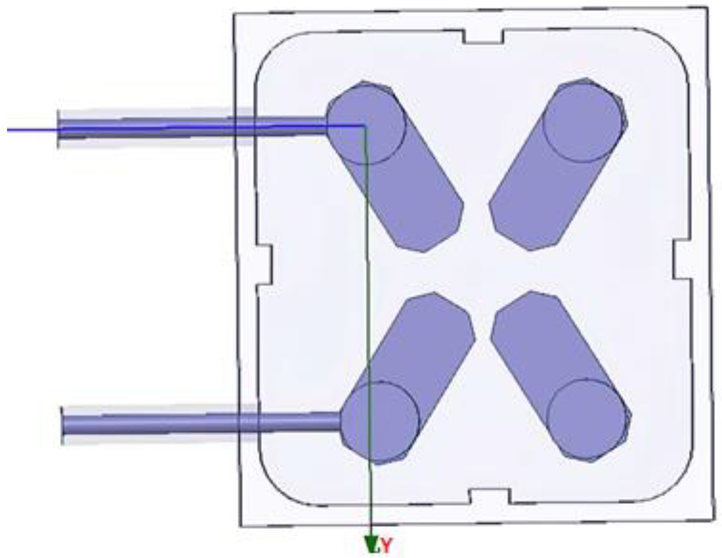
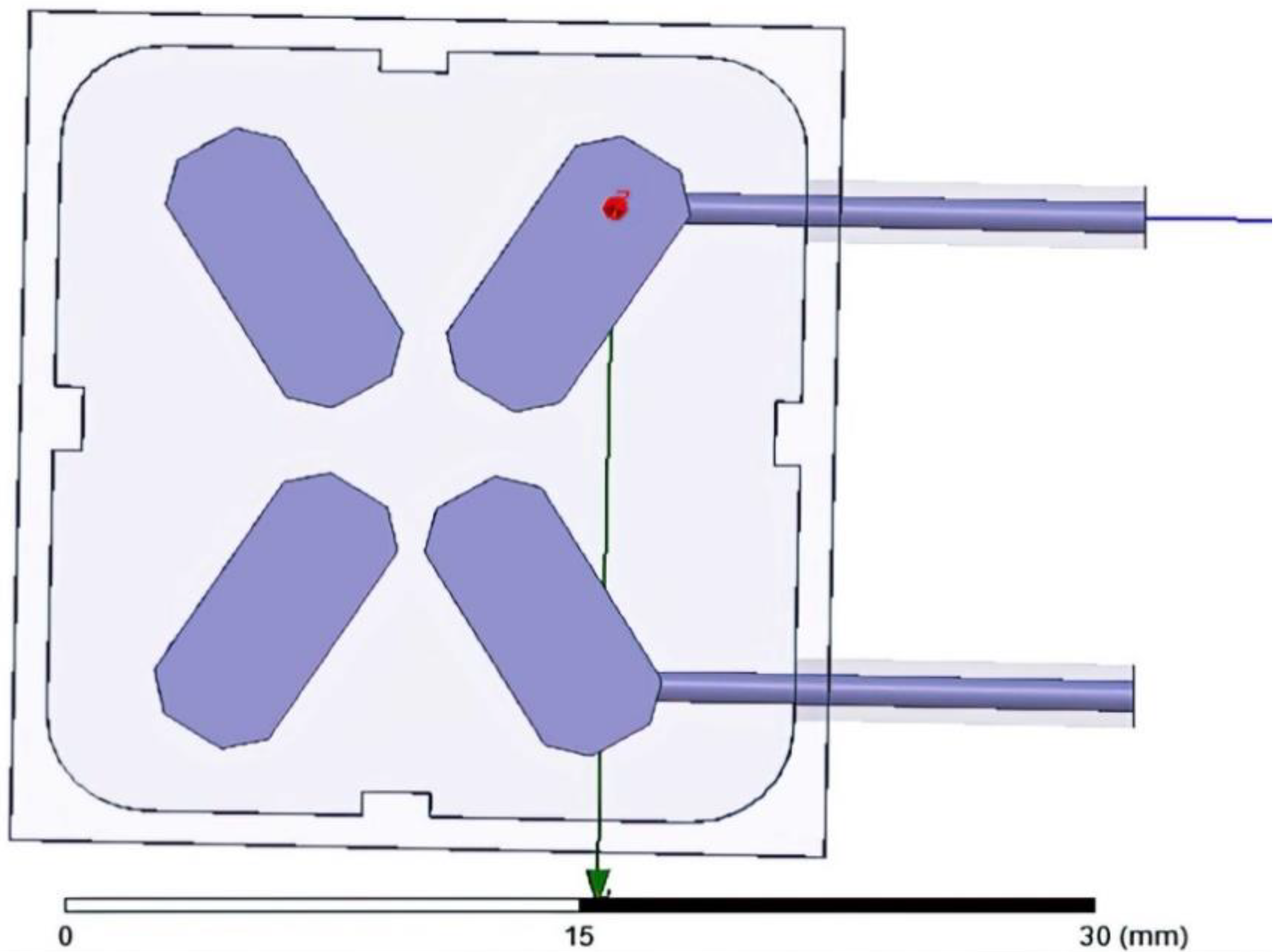
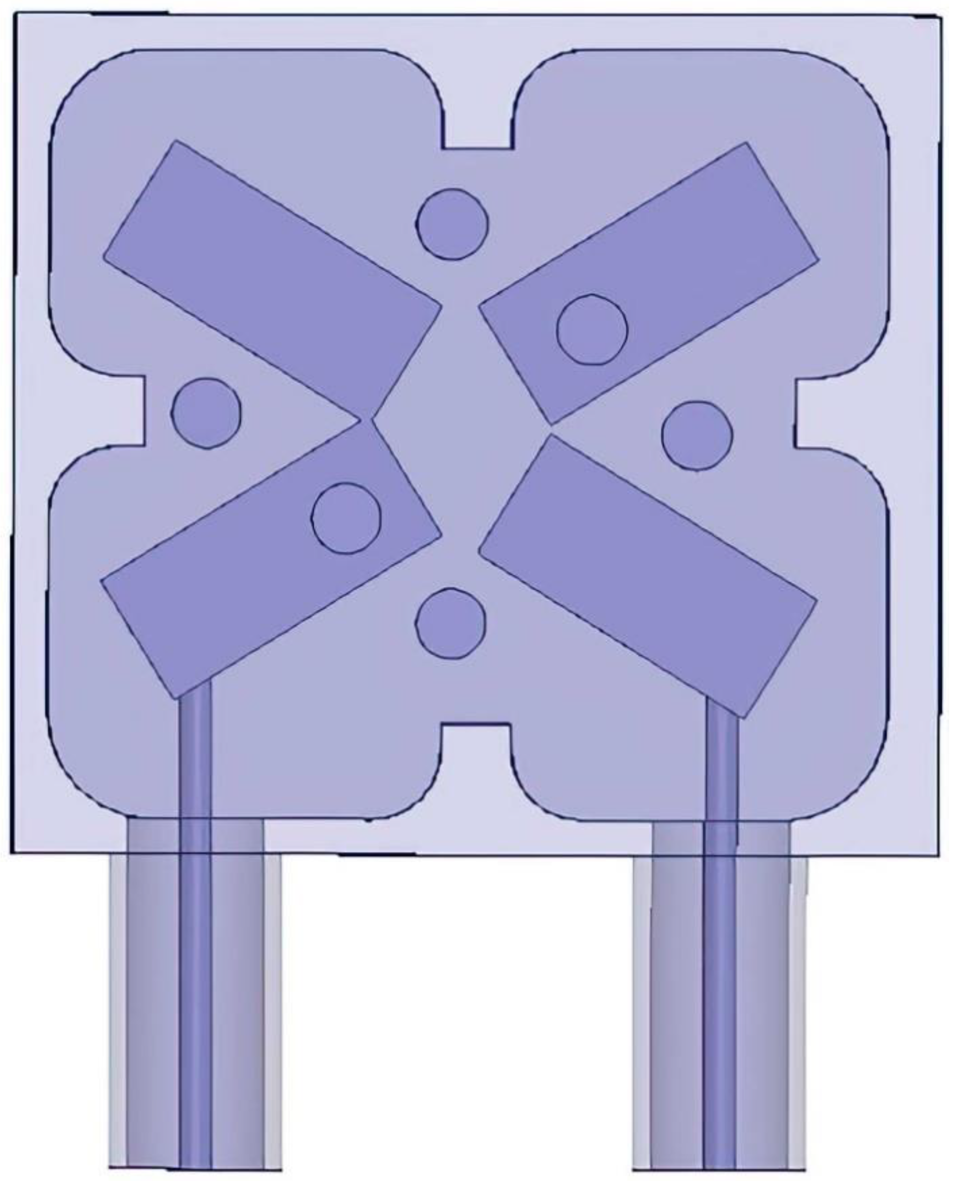
4. Quadruple-Mode Resonator
5. Proposed Configurations and Characteristics
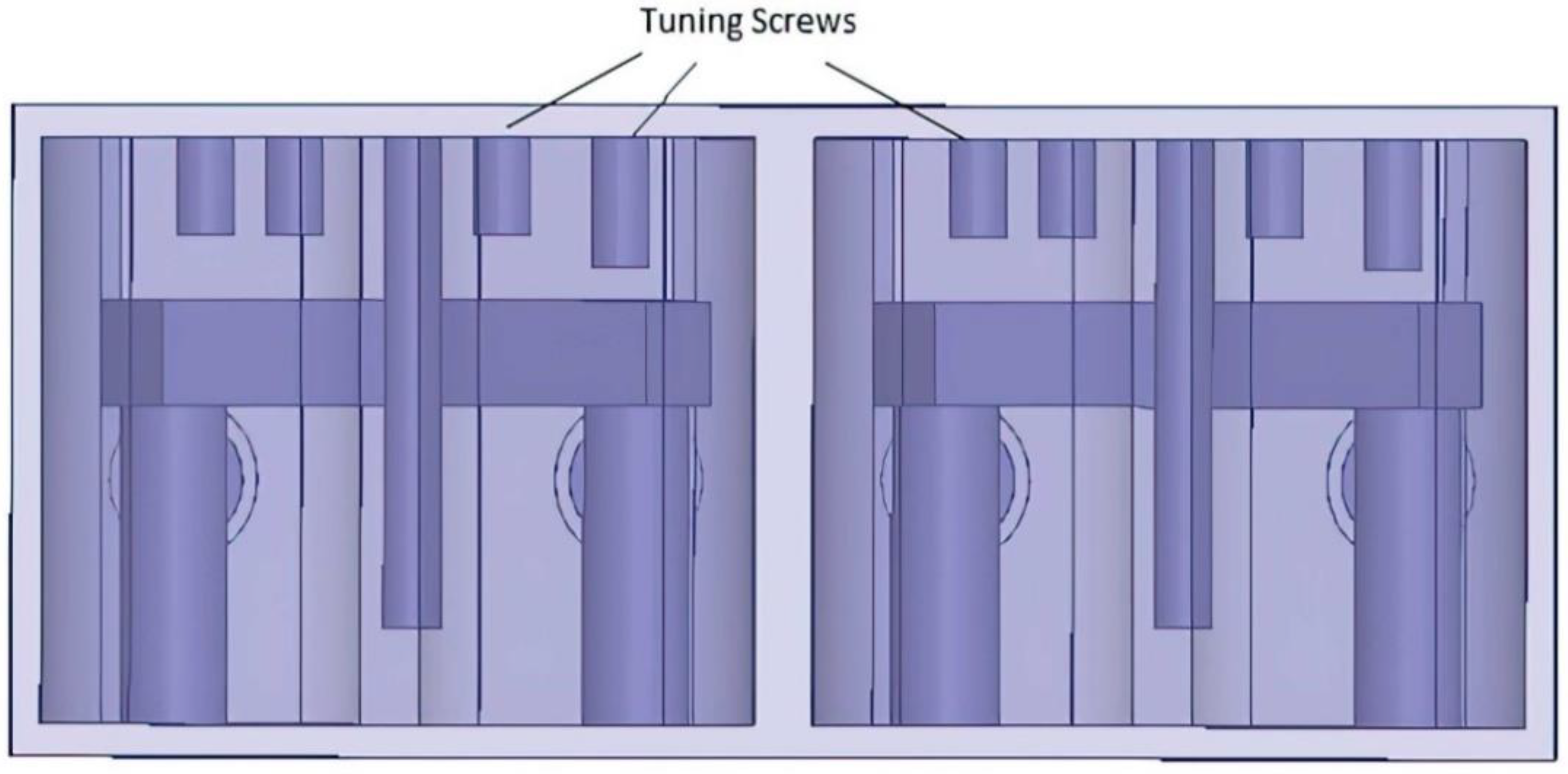
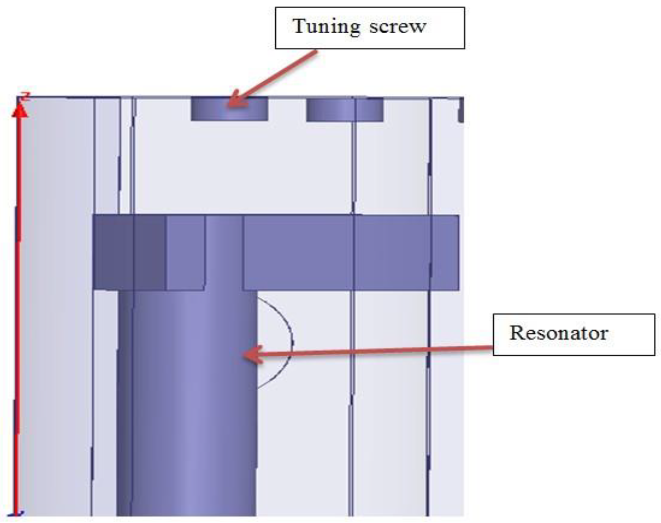
6. Cavity Filter Design
7. Normalized Capacitance between Resonators and Ground
8. Physical Filter Dimensions
9. Coaxial Resonator Cavity Filters
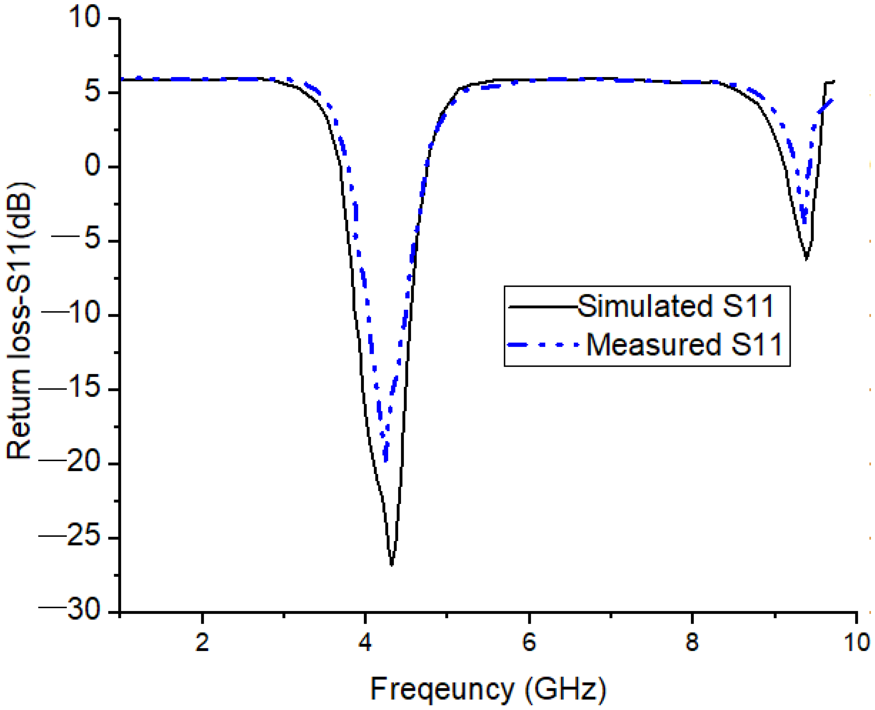
10. Results
11. Comparative Analysis of Conventional and Proposed Resonators
12. Conclusions
Author Contributions
Funding
Data Availability Statement
Acknowledgments
Conflicts of Interest
References
- Hameed, M.; Xiao, G.; Qiu, L.; Xiong, C.; Hameed, T. Multiple-Mode Wideband Bandpass Filter Using Split Ring Resonators in a Rectangular Waveguide Cavity. Electronics 2018, 7, 356. [Google Scholar] [CrossRef] [Green Version]
- Basavarajappa, G.; Mansour, R.R. A high-Q quadruple-mode rectangular waveguide resonator. IEEE Microw. Wirel. Compon. Lett. 2019, 29, 324–326. [Google Scholar] [CrossRef]
- Campanella, H.; Qian, Y.; Romero, C.O.; Wong, J.S.; Giner, J.; Kumar, R. Monolithic Multiband MEMS RF Front-End Module for 5G Mobile. J. Microelectromechanical Syst. 2021, 30, 72–80. [Google Scholar] [CrossRef]
- Sardi, A.; Alkurt, F.Ö.; Özkaner, V.; Karaaslan, M.; Ünal, E.; Mohamed, T. Investigation of microwave power limiter for In-dustrial Scientific Medical band (ISM) applications. Int. J. RF Microw. Comput.-Aided Eng. 2020, 30, e22180. [Google Scholar] [CrossRef]
- Watanabe, A.O.; Ali, M.; Sayeed, S.Y.B.; Tummala, R.R.; Pulugurtha, M.R. A Review of 5G Front-End Systems Package Integration. IEEE Trans. Compon. Packag. Manuf. Technol. 2021, 11, 118–133. [Google Scholar] [CrossRef]
- Mahmud, R.; Awl, H.N.; Abdulkarim, Y.I.; Karaaslan, M.; Lancaster, M.J. Filtering two-element waveguide antenna array based on solely resonators. AEU-Int. Electron. Commun. 2020, 121, 153232. [Google Scholar] [CrossRef]
- Nivethitha, T.; Palanisamy, S.K.; Prakash, K.M.; Jeevitha, K. Comparative study of ANN and fuzzy classifier for forecasting electrical activity of heart to diagnose Covid-19. Mater. Today Proc. 2021, 45, 2293–2305. [Google Scholar] [CrossRef]
- Alotaibi, Y.; Almagrabi, A.O.; Alsufyani, A.; Alghamdi, S.A.; Alsufyani, N. Emerging recent innovative technologies based on sustainable business models for logistics 4.0. Soft Comput. 2021. accepted. [Google Scholar]
- Alsufyani, A.; Alotaibi, Y.; Almagrabi, A.O.; Alghamdi, S.A.; Alsufyani, N. Optimized intelligent data management framework for a cyber-physical system for computational applications. Complex Intell. Syst. 2021, 1–13. [Google Scholar] [CrossRef]
- Veeraiah, N.; Khalaf, O.I.; Prasad, C.V.P.R.; Alotaibi, Y.; Alsufyani, A.; Alghamdi, S.A.; Alsufyani, N. Trust Aware Secure Energy Efficient Hybrid Protocol for MANET. IEEE Access 2021, 9, 120996–121005. [Google Scholar] [CrossRef]
- Alotaibi, Y.; Malik, M.N.; Khan, H.H.; Batool, A.; Islam, S.U.; Alsufyani, A.; Alghamdi, S. Suggestion Mining from Opinionated Text of Big Social Media Data. Comput. Mater. Contin. 2021, 68, 3323–3338. [Google Scholar] [CrossRef]
- Zhang, X.Y.; Chen, J.-X.; Xue, Q.; Li, S.-M. Dual-Band Bandpass Filters Using Stub-Loaded Resonators. IEEE Microw. Wirel. Compon. Lett. 2007, 17, 583–585. [Google Scholar] [CrossRef]
- Suryanarayana, G.; Chandran, K.; Khalaf, O.I.; Alotaibi, Y.; Alsufyani, A.; Alghamdi, S.A. Accurate Magnetic Resonance Image Super-Resolution Using Deep Networks and Gaussian Filtering in the Stationary Wavelet Domain. IEEE Access 2021, 9, 71406–71417. [Google Scholar] [CrossRef]
- Li, G.; Liu, F.; Sharma, A.; Khalaf, O.I.; Alotaibi, Y.; Alsufyani, A.; Alghamdi, S. Research on the Natural Language Recognition Method Based on Cluster Analysis Using Neural Network. Math. Probl. Eng. 2021, 2021, 9982305. [Google Scholar] [CrossRef]
- Alotaibi, Y. A New Database Intrusion Detection Approach Based on Hybrid Meta-heuristics. CMC-Comput. Mater. Contin. 2021, 66, 1879–1895. [Google Scholar] [CrossRef]
- Bharany, S.; Sharma, S.; Badotra, S.; Khalaf, O.I.; Alotaibi, Y.; Alghamdi, S.; Alassery, F. Energy-Efficient Clustering Scheme for Flying Ad-Hoc Networks Using an Optimized LEACH Protocol. Energies 2021, 14, 6016. [Google Scholar] [CrossRef]
- Palanisamy, S.; Thangaraju, B.; Khalaf, O.I.; Alotaibi, Y.; Alghamdi, S.; Alassery, F. A Novel Approach of Design and Analysis of a Hexagonal Fractal Antenna Array (HFAA) for Next-Generation Wireless Communication. Energies 2021, 14, 6204. [Google Scholar] [CrossRef]
- Luo, S.; Zhu, L. A Novel Dual-Mode Dual-Band Bandpass Filter Based on a Single Ring Resonator. IEEE Microw. Wirel. Compon. Lett. 2009, 19, 497–499. [Google Scholar]
- Li, Y.C.; Wong, H.; Xue, Q. Dual-Mode Dual-Band Bandpass Filter Based on a Stub-Loaded Patch Resonator. IEEE Microw. Wirel. Compon. Lett. 2011, 21, 525–527. [Google Scholar] [CrossRef]
- Bagci, F.; Fernández-Prieto, A.; Lujambio, A.; Martel, J.; Bernal, J.; Medina, F. Compact balanced dualband bandpass filter based on modified cou-pled-embedded resonators. IEEE Microw. Wireless Compon. Lett. 2017, 27, 31–33. [Google Scholar] [CrossRef]
- Alotaibi, Y. Automated Business Process Modelling for Analyzing Sustainable System Requirements Engineering. In Proceedings of the 2020 6th International Conference on Information Management (ICIM) IEEE, London, UK, 27–29 March 2020; pp. 157–161. [Google Scholar]
- Jha, N.; Prashar, D.; Khalaf, O.I.; Alotaibi, Y.; Alsufyani, A.; Alghamdi, S. Blockchain Based Crop Insurance: A Decentralized Insurance System for Modernization of Indian Farmers. Sustainability 2021, 13, 8921. [Google Scholar] [CrossRef]
- Nam, S.; Lee, B.; Kwak, C.; Lee, J. A New Class of K-Band High-Q Frequency-Tunable Circular Cavity Filter. IEEE Trans. Microw. Theory Tech. 2017, 66, 1228–1237. [Google Scholar] [CrossRef]
- Subramanyam, A.V.G.; Sivareddy, D.; Krishna, V.V.; Srinivasan, V.V.; Mehta, Y. Compact Iris-Coupled Evanescent-Mode Filter for Spacecraft S-Band Data Transmitters. In Proceedings of the IEEE International Microwave and RF Conference (IMaRC), Hyderabad, India, 10–12 December 2015. [Google Scholar]
- Wibisono, G.; Firmansyah, T.; Herudin, H.; Wildan, M.; Supriyanto, T.; Alaydrus, M.; Ujang, F. Multi wideband Bandpass Filter Based on Folded Quad Cross-Stub Stepped Impedance Resonator. Int. J. Antennas Propag. 2020, 2020, 4124721. [Google Scholar] [CrossRef]
- Al-Yasir, Y.I.A.; Parchin, N.O.; Abdulkhaleq, A.M.; Bakr, M.S.; Abd-Alhameed, R.A. A Survey of Differential-Fed Microstrip Bandpass Filters: Recent Techniques and Challenges. Sensors 2020, 20, 2356. [Google Scholar] [CrossRef] [Green Version]
- Wang, X.; Jang, G.; Lee, B.; Park, N. Compact Quad-Mode Bandpass Filter Using Modified Coaxial Cavity Resonator With Improved Q-Factor. IEEE Trans. Microw. Theory Tech. 2015, 63, 965–975. [Google Scholar] [CrossRef]
- Yassini, B.; Yu, M.; Keats, B. A Ka-Band Fully Tunable Cavity Filter. IEEE Trans. Microw. Theory Tech. 2012, 60, 4002–4012. [Google Scholar] [CrossRef]
- Kumar, P.S.; Jeevitha; Manikanda. Diagnosing COVID-19 Virus in the Cardiovascular System Using ANN. In Artificial Intelligence for COVID-19; Oliva, D., Hassan, S.A., Mohamed, A., Eds.; Studies in Systems, Decision and Control; Springer: Cham, Switzerland, 2021; Volume 358, pp. 63–75. [Google Scholar] [CrossRef]
- Kumar, P.S.; Valarmathy, S. Development of a novel algorithm for SVMBDT fingerprint classifier based on clustering approach. In Proceedings of the IEEE-International Conference On Advances In Engineering, Science And Management (ICAESM-2012), Nagapattinam, India, 30–31 March 2012; pp. 256–261. [Google Scholar]
- Wang, P.; Li, L.; Wei, S. Design of a tunable S-band narrow-band coaxial cavity filter. In Proceedings of the 2012 IEEE International Conference on Microwave and Millimeter Wave Technology (ICMMT), Shenzhen, China, 5–8 May 2012. [Google Scholar]
- Wang, Y.; Yu, M. True Inline Cross-Coupled Coaxial Cavity Filters. IEEE Trans. Microw. Theory Tech. 2009, 57, 2958–2965. [Google Scholar] [CrossRef]
- Du, X.; Tang, P.; Chen, B. Design of a C-band coaxial cavity band pass filter. In Proceedings of the PIERS, Guangzhou, China, 25–28 August 2014; pp. 1065–1068. Available online: https://www.piers.org/pierspublications/PIERS2014GuangzhouProceedings02.pdf (accessed on 9 September 2021).
- Zhan, Y.; Chen, J.-X.; Qin, W.; Li, J.; Bao, Z.-H. Spurious-Free Differential Bandpass Filter Using Hybrid Dielectric and Coaxial Resonators. IEEE Microw. Wirel. Compon. Lett. 2016, 26, 574–576. [Google Scholar] [CrossRef]
- Kurudere, S.; Erturk, V.B. Novel Microstrip Fed Mechanically Tunable Combline Cavity Filter. IEEE Microw. Wirel. Compon. Lett. 2013, 23, 578–580. [Google Scholar] [CrossRef] [Green Version]
- Yuceer, M. A Reconfigurable Microwave Combline Filter. IEEE Trans. Circuits Syst. II Express Briefs 2015, 63, 84–88. [Google Scholar] [CrossRef]


| a | L | h | r | d |
|---|---|---|---|---|
| 33 mm | 15 mm | 18 mm | 3 mm | 10 mm |
| Filter Type | Volume (mm3) | Quality Factor, Q | Bandwidth, BW | Resonant Frequency | Return Loss (dB) | Insertion Loss (dB) | Transmission Zeros |
|---|---|---|---|---|---|---|---|
| Conventional quadruple mode BPF [25] | 18,513 (33 mm × 33 mm × 17 mm) | 0.865 | 600 MHz | 2566.8 MHz | −20 | −32 | 2 |
| Two-pole quadruple mode BPF [26] | 14510 (26 mm × 26 mm × 20 mm) | 2.1 | 850 MHz | 4250 MHz | ≥−12 | −42 | 2 |
| Compact quad-mode bandpass filter [27] | 13,520 (24 mm × 24 mm × 20 mm) | 3.1 | 840 MHz | 4350 MHz | −27 | −35 | 4 |
| Proposed filter in this paper (four-pole quadruple mode BPF) | 13,122 (27 mm × 27 mm × 18 mm) | 4.3 | 880 MHz | 4250 MHz | −32 (simulated) −26 (measured) | −62 | 4 |
Publisher’s Note: MDPI stays neutral with regard to jurisdictional claims in published maps and institutional affiliations. |
© 2021 by the authors. Licensee MDPI, Basel, Switzerland. This article is an open access article distributed under the terms and conditions of the Creative Commons Attribution (CC BY) license (https://creativecommons.org/licenses/by/4.0/).
Share and Cite
Palanisamy, S.; Thangaraju, B.; Khalaf, O.I.; Alotaibi, Y.; Alghamdi, S. Design and Synthesis of Multi-Mode Bandpass Filter for Wireless Applications. Electronics 2021, 10, 2853. https://doi.org/10.3390/electronics10222853
Palanisamy S, Thangaraju B, Khalaf OI, Alotaibi Y, Alghamdi S. Design and Synthesis of Multi-Mode Bandpass Filter for Wireless Applications. Electronics. 2021; 10(22):2853. https://doi.org/10.3390/electronics10222853
Chicago/Turabian StylePalanisamy, Satheeshkumar, Balakumaran Thangaraju, Osamah Ibrahim Khalaf, Youseef Alotaibi, and Saleh Alghamdi. 2021. "Design and Synthesis of Multi-Mode Bandpass Filter for Wireless Applications" Electronics 10, no. 22: 2853. https://doi.org/10.3390/electronics10222853
APA StylePalanisamy, S., Thangaraju, B., Khalaf, O. I., Alotaibi, Y., & Alghamdi, S. (2021). Design and Synthesis of Multi-Mode Bandpass Filter for Wireless Applications. Electronics, 10(22), 2853. https://doi.org/10.3390/electronics10222853