1. Introduction
With the development of electric drive technology, the electrification of propulsion systems on marine vessels will likely become a trend in the future. Although induction motors have been widely used in many fields, in the field of marine vessel propulsion, induction motors still have many shortcomings [
1]. Compared with traditional induction motors, DTPIMs have the following advantages [
2,
3,
4]: (1) the electromagnetic torque ripple is less, and the performance of the motor is improved. (2) It can be used in low-voltage and high-power AC drive systems. (3) The reliability of the motor is greatly enhanced, and the motor can still maintain its running stability by changing the control strategy when an open-phase fault occurs. Therefore, in high-power and high-reliability drive systems, such as marine vessel propulsion systems, DTPIMs have become more popular [
5].
Marine vessels usually voyage on the sea for a long time, and their motors work in harsh environments with high temperatures and high humidity, which pose severe challenges to the reliability of motor operation. Motors may encounter various types of faults [
6], but current fault-tolerant-control research mainly focuses on cases of stator winding faults, such as stator winding short-circuit and open-circuit faults [
7,
8]. The motor drive systems require real-time rotor speed information for closed-loop control. However, the commonly used speed sensors are precision devices, which are greatly affected and easily become faulty when used in harsh environments [
9]. Therefore, in the case of sensor damage or failure in the motor drive system, it is of great practical value to estimate the rotor speed by detecting the stator voltage and the stator current, in order to realize fault-tolerant control operation after the fault occurs.
At present, speed-estimation algorithms mainly include the MRAS method [
10], the sliding-mode observer method [
11], and the extended Kalman filter method [
12]. Among them, the sliding-mode observer method has a chattering problem, especially in discrete control. The extended Kalman filter method requires a large number of adjustment parameters and is computationally complex [
13]. Therefore, MRAS has received attention from researchers because of its simple algorithm, strong anti-interference ability, and high steady-state accuracy [
14]. A new rotor-position observation method was proposed in [
15] based on MRAS. An MRAS method based on a second-order sliding mode strategy was proposed in [
16] for direct torque control systems. The rotor time constant was identified based on MRAS in [
17].
The MRAS speed-estimation method is composed of a current model, including the speed variable, and a voltage model, excluding the speed variable [
18]. This algorithm is practical, but stator resistance can be affected by factors such as motor temperature rise, and the stator resistance value will change correspondingly, which has a negative impact on the accuracy of the speed-estimation [
19,
20].
In this paper, two MRAS speed-estimation methods are proposed, based on DCS and VSD, respectively. The online stator resistance identification method is imported to solve the existing problem of MRAS speed-estimation. The imported stator resistance identification method could improve the accuracy of the speed-estimation algorithm. It could effectively reduce the impact of changes to the stator resistance value on the accuracy of the speed-estimation. In addition, the above analyses were verified by simulation results.
2. DTPIM Analysis Based on the VSD Method
2.1. The Structure of DTPIM
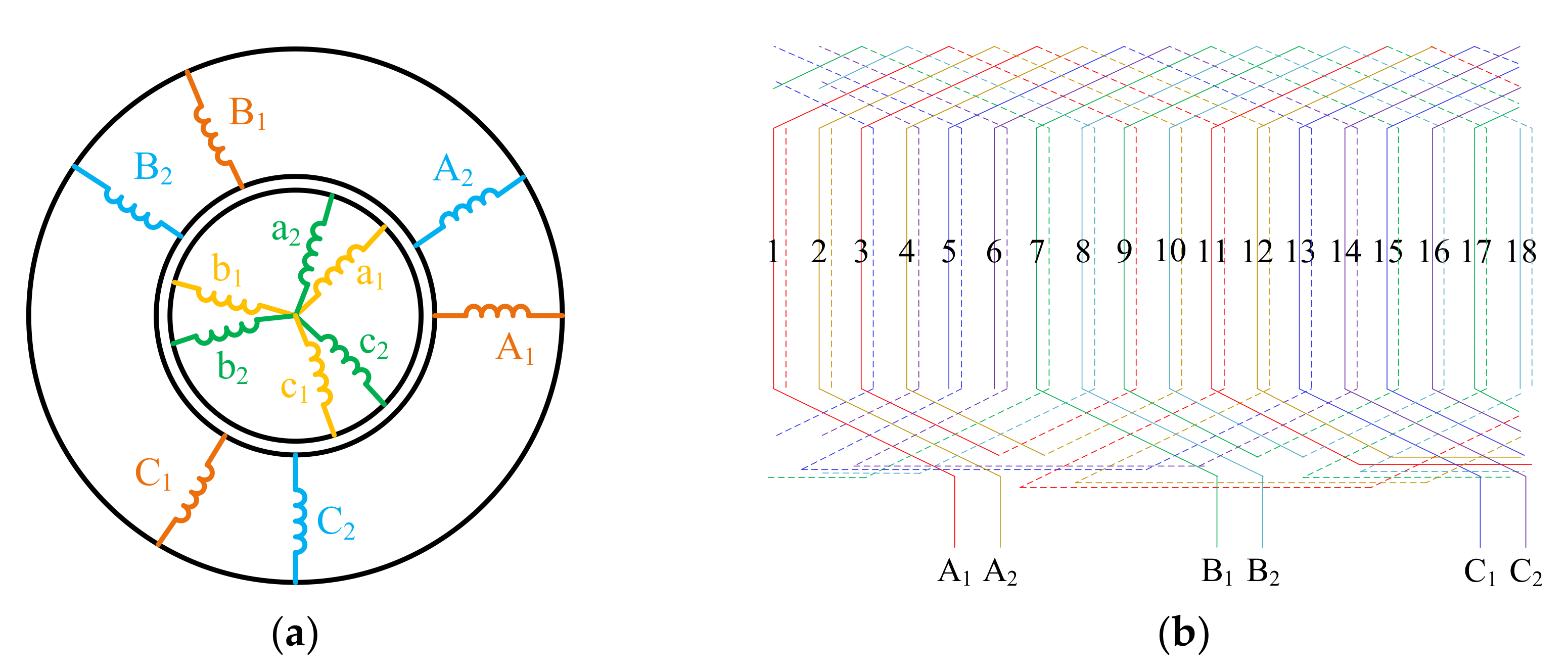
The stator windings of the DTPIM are composed of two sets of three-phase windings with the same structure. The two sets of windings have a 30° electrical degree phase difference in space. The rotor structure is the same as that of the traditional induction motor. The structure of the DTPIM and the distribution of the stator windings are shown in
Figure 1.
2.2. Vector Space Decomposition
The mathematical model of the DTPIM is a six-dimensional time-varying system, which is difficult to analyze directly in the natural coordinate system. Therefore, to ease the difficulty level of motor control, VSD was used to map the DTPIM from the natural coordinate system to three subspaces, (α, β), (γ, δ), and (o
1, o
2), which are orthogonal to each other. The subspace (α, β) was the fundamental space, and the motor could be controlled through this subspace. The DTPIM was powered by a dual three-phase inverter, as shown in
Figure 2.
The six bridge arms provided 2
6 = 64 switch states, corresponding to 64 space voltage vectors, including 60 non-zero voltage vectors and 4 zero voltage vectors. The 64 spatial voltage vectors were mapped to three 2-D subspaces, (α, β), (γ, δ), and (o
1, o
2), by VSD. Since the motor stator windings had two neutral points, the voltage vectors in the subspace (o
1, o
2) were 0. The voltage vectors mapped to subspaces (α, β) and (γ, δ) are shown in
Figure 3.
It can be seen from
Figure 3a that the 12 outermost vectors had the largest amplitudes, while the corresponding 12 vectors in
Figure 3b had the smallest amplitudes. Therefore, the 12 outermost vectors in
Figure 3a were selected as the basic voltage vectors for achieving maximum voltage utilization and minimum stator harmonic currents. The amplitudes of the 12 outermost vectors in
Figure 3a were equal, and can be expressed as:
In order to further suppress the harmonic currents, every four adjacent voltage vectors in the 12 outermost voltage vectors were synthesized into a new virtual voltage vector, which let the volt-second characteristics of these four voltage vectors in the subspace (γ, δ) be zero.
The adjacent voltage vectors
U11,
U9,
U41, and
U45 (shown in the shaded part of
Figure 3) are taken as an example to synthesize the virtual voltage vector
U1im. Due to the fact that the volt-second characteristic is 0:
the synthesized virtual voltage vector is:
By solving Equations (2) and (3), the synthesized virtual voltage vector amplitude is found to be:
In the same way, the remaining 11 virtual voltage vectors can be obtained. These 12 virtual voltage vectors divided the subspace (α, β) into 12 equal sectors, as shown in
Figure 4. At this time, the SVPWM algorithm of the dual three-phase inverter has been simplified from the six-dimensional space to the two-dimensional space.
3. Speed-Estimation Methods for DTPIM Based on DCS and VSD without Stator Resistance Identification
3.1. Speed-Estimation Based on DCS
Since the stator windings of the motor have two neutral points, the stator windings can be regarded as two sets of independent windings to perform the Clarke transformation. The (α
1, β
1) and (α
2, β
2) coordinate systems are shown in
Figure 5.
The rotor flux voltage model based on DCS is shown in Equation (5).
The current model is shown in Equation (6).
where n = 1,2 represent the first and second sets of windings, respectively, σ is the magnetic leakage coefficient, and
Tr is the rotor time constant.
The output error
ε1 of the first set of windings is defined as:
The output error
ε2 of the second set of windings is defined as:
The design method of the adaptive system based on Popov hyper-stability theory can be described as follows:
In a nonlinear time-varying system, an appropriate adaptive law is designed according to the model characteristics to make the whole system meet the requirements of hyper-stability. That is, to make the system error zero or infinitely close to zero. At this time, the output parameters of the adjustable model and the reference model are approximately equal. Eventually, adaptive control is realized. The adaptive law usually acts as a form of PI.
According to Popov hyper-stability theory, the speed-adaptive law based on DCS is constructed:
where
kpn,
kin are the proportional coefficient and the integral coefficient, respectively.
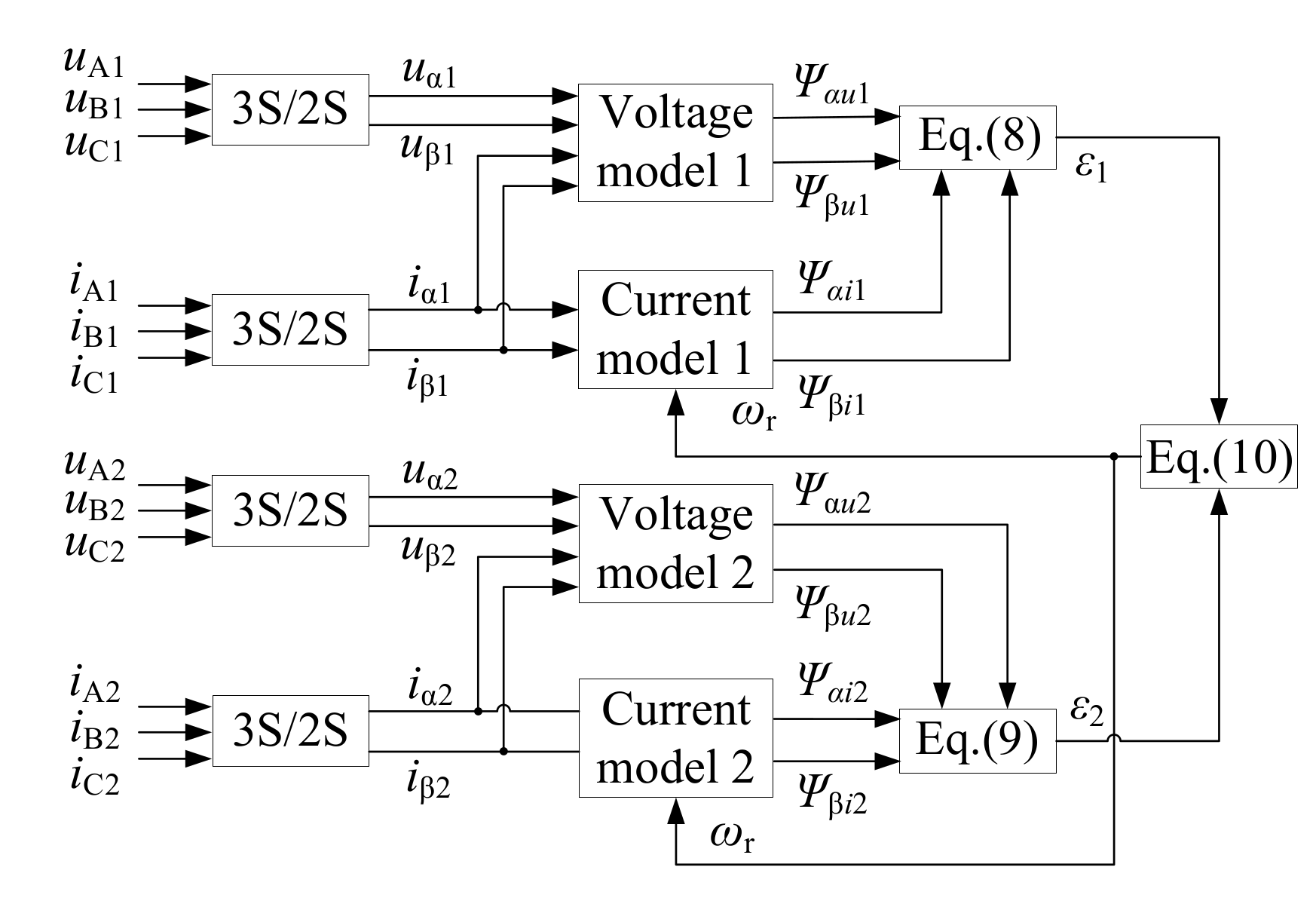
The block diagram of speed-estimation without the stator resistance identification method based on DCS is shown in
Figure 6.
3.2. Speed-Estimation Based on VSD
The rotor speed of DTPIM is estimated by using VSD in the (α, β) coordinate system. The voltage model of rotor flux is shown in Equation (5), and the current model is shown in Equation (6).
The output error
ε3 of the voltage model and current model is defined as:
According to Popov hyper-stability theory, the speed-adaptive law based on VSD is constructed:
The block diagram of speed-estimation without the stator resistance identification method based on VSD is shown in
Figure 7.
4. Speed-Estimation Methods for DTPIM Based on DCS and VSD with Stator Resistance Identification
The stator resistance value is not constant, and is affected by temperature rises of the motor. As a result, the rotor flux calculated according to the voltage model will also be inaccurate, which will lead to some error in the estimated speed.
In this paper, a speed-estimation strategy is proposed for DTPIM with the stator resistance identification method. In this method, the voltage model is regarded as the adjustable model and the current model as the reference model. The identified stator resistance value is imported into the voltage model. Thus, the MRAS speed-estimation system, with the stator resistance estimation method, is constructed, which can make speed-estimation more accurate when the stator resistance value changes.
4.1. Stator Resistance Identification Based on DCS
The output error
ε4 of the first set of windings is defined as:
The output error
ε5 of the second set of windings is defined as:
According to Popov hyper-stability theory, the adaptive law of stator resistance based on DCS is constructed:
The block diagram of speed-estimation with the stator resistance identification method based on DCS is shown in
Figure 8.
4.2. Stator Resistance Identification Based on VSD
The output error
ε6 of the rotor flux is defined as:
According to Popov hyper-stability theory, the adaptive law of stator resistance based on VSD is constructed:
The block diagram of speed-estimation with the stator resistance identification method based on VSD is shown in
Figure 9.
4.3. Direct Torque Control of DTPIM
The direct torque control system generates voltage vectors
and
through two PI regulators. Then, the reference voltage vector
=
+
is obtained by the rotating coordinate transformation, which is used as the input signal of the SVPWM module. Finally, the motor is driven by a dual three-phase inverter. This strategy does not need to query the voltage-space-vector switch table, which can reduce the ripple of the electromagnetic torque. The direct torque control structure diagram of the DTPIM is shown in
Figure 10.
5. Simulation and Results Analysis
For verifying the correctness of the proposed speed-estimation methods, the DTPIM system was modeled and simulated by MATLAB/Simulink. The solver selection selected variable-step, and the solver selected ode45. The motor parameters were as follows: rated power PN = 7.5 kW, rated speed ωN = 1440 r/min, stator resistance Rs = 11.6 Ω, stator self-inductance Ls = 0.579 H, rotor resistance Rr = 10.4 Ω, rotor self-inductance Lr = 0.579 H, the mutual inductance between stator windings and rotor windings Lm = 0.557 H, the moment of inertia J = 0.002 kg·m2, the number of pole pairs P = 2, and the number of slots was 36.
5.1. Speed-Estimation of DTPIM without Stator Resistance Identification
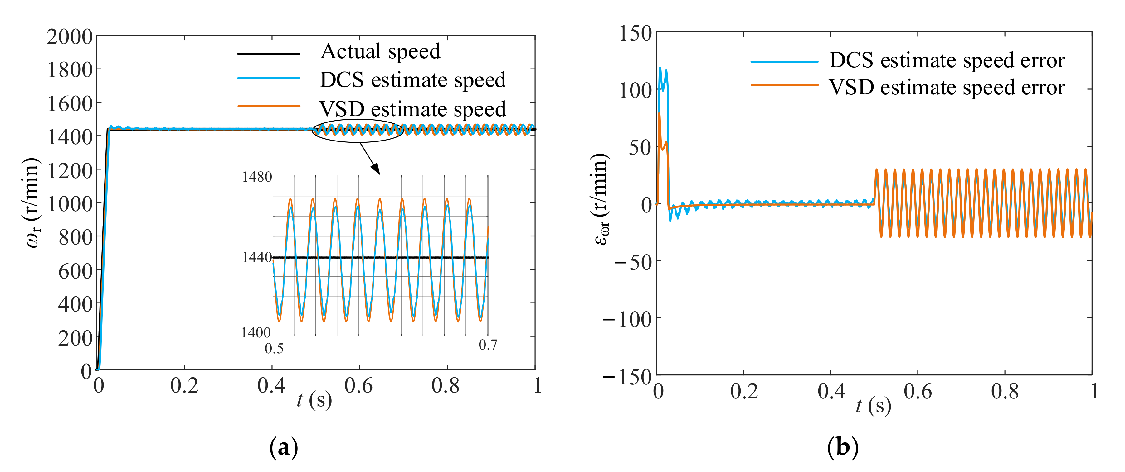
The motor started without a load, and the reference speed was 1440 r/min. After 0.3 s, the reference speed was 1325 r/min, and the load torque was 10 N·m. After 0.7 s, the reference speed was 1440 r/min, and the load torque was 5 N·m. The actual speed and the estimated speed, based on DCS and VSD under dynamic conditions, are shown in
Figure 11.
It can be seen from
Figure 11 that both methods could accurately estimate speed. Although there were some errors during the process of motor starting and the load state changing, the actual value could be estimated quickly and reliably after the motor ran stably. When the motor was running stably, the speed error of the DCS method was about 3 r/min, and that of the VSD method was within 0.5 r/min.
Stator resistance is affected by temperature rise during the actual operation of the motor. If the stator resistance value becomes 1.3 times the initial set value, and the speed-estimation strategy still estimates according to the initial setting value of 11.6 Ω, the following results are seen. The speed-estimation results under steady conditions are shown in
Figure 12. The speed-estimation results under dynamic conditions are shown in
Figure 13.
It can be seen from
Figure 12 and
Figure 13 that when the reference stator resistance value of the speed-estimation module was wrong, whether the motor was running in steady conditions or in dynamic conditions, both of the rotor speeds estimated by the DCS and VSD methods fluctuated sharply. Specifically, the two kinds of speed errors were at the same level, and were about 270–400 r/min.
5.2. Speed-Estimation Based on DCS and VSD Methods under Steady Conditions
Figure 14 shows the actual stator resistance value and the identified stator resistance value, based on DCS and VSD, when the motor was started without load and the reference speed was 1440 r/min.
It can be seen from
Figure 14 that after the motor ran for 0.3 s, the two stator resistance estimation methods had basically finished tracking the initial set value of 11.6 Ω. The estimation error under the DCS method was about 0.5 Ω, and the estimation error under the VSD method was within 0.02 Ω. In the motor running process, the initial reference resistance value was used for speed-estimation in the first 0.3 s, and the stator resistance online identification was introduced after 0.3 s.
It was assumed that an abrupt change of the stator resistance value, 1.3 times the initial setting value, was applied after running for 0.5 s. The speed-estimation results before and after importing the online identification method of stator resistance are shown in
Figure 15 and
Figure 16, respectively.
It can be seen from
Figure 15 and
Figure 16 that when the actual resistance value changed under steady conditions, the speed-estimation results based on DCS and VSD fluctuated continuously before the stator resistance identification method was introduced. Both of the speed errors were about 30 r/min.
The initial speed errors of the two methods were about 30 r/min after the stator resistance identification method was imported. After 0.2 s, the estimated speed based on the DCS method was basically stable, but there was still an 8r/min speed error due to the effect of stator harmonic currents. The VSD speed-estimation method was carried out in the subspace (α, β), without harmonic components, so the estimation speed was more stable after 0.2 s, and the error was within 2 r/min.
5.3. Speed-Estimation Based on DCS and VSD Methods under Dynamic Conditions
Figure 17 shows the output electromagnetic torque under dynamic conditions. It can be seen from
Figure 17 that when the stator resistance value changed under dynamic conditions, there was a large ripple in the electromagnetic torque. After the stator resistance identification was imported, the torque ripple decreased rapidly. Unaffected by the harmonic currents, the electromagnetic torque ripple of the VSD method was lower than that of the DCS method. The speed-estimation results before and after importing the online identification of stator resistance are shown in
Figure 18 and
Figure 19, respectively.
It can be seen from
Figure 18 and
Figure 19 that when the actual resistance value changed under dynamic conditions, the speed-estimation results based on DCS and VSD fluctuated continuously before the stator resistance identification method was imported. Both of the speed errors were about 50 r/min.
The initial speed errors of the two methods were about 40 r/min after the stator resistance identification method was imported. Likewise, affected by the stator harmonic current, the error of the DCS method was about 14 r/min after 0.2 s, while the error of the VSD method was only about 4 r/min.
6. Conclusions
In this paper, two MRAS speed-estimation methods were proposed, based on DCS and VSD, considering the two groups of the three-phase armature vectors of the DTPIM. These two methods were developed for vessel propulsion DTPIM speed-sensorless control systems in order to improve system reliability under harsh environments. The changing of the stator resistance value caused by temperature variation affects the accuracy of the speed-estimation. Therefore, combining DCS and VSD speed-estimation methods, two online resistance identification algorithms were proposed. Both of the two algorithms could accurately identify the value of the stator resistance after it changed, thereby improving the accuracy of speed-estimation. Both the torque and the speed ripple of the control system could be effectively suppressed. In the DCS method, the speed-estimation error was large, due to the existence and the influence of the stator harmonic currents, while in the VSD method, the speed-estimation error was small and the estimation result had high accuracy. The main reason for this was that the selected armature vectors in subspace (α, β) had only small harmonic components. Simulation results showed that the dynamic speed-estimation error of the VSD method decreased by 71% compared with the DCS method. Therefore, the estimation performance of the VSD method is better than that of the DCS method.
The VSD method presented in this paper lays a foundation for the establishment of a high-precision, fault-tolerant control operation scheme for onboard propulsion systems, especially in the cases of driving force insufficiency or control accuracy deficiency caused by speed sensor failure.
Author Contributions
Conceptualization, C.X. and F.Y.; methodology, F.Y. and J.Z.; software, C.X.; validation, C.X.; formal analysis, C.X., F.Y. and J.Z.; investigation, C.X. and F.Y.; resources, F.Y. and J.Z.; data curation, C.X. and F.Y.; writing—original draft preparation, C.X.; writing—review and editing, C.X. and F.Y.; visualization, C.X.; supervision, F.Y. and J.Z.; project administration, F.Y.; funding acquisition, F.Y. All authors have read and agreed to the published version of the manuscript.
Funding
This research was funded in part by the Natural Science Foundation of Shanghai under Grant 21ZR1402300, and in part by the Fundamental Research Funds for the Central Universities under Grant 2232019D3-53.
Conflicts of Interest
The authors declare no conflict of interest.
Nomenclature
| DTPIM | Dual three-phase induction motor. |
| VSD | Vector space decomposition. |
| DCS | Double (α, β) coordinate systems. |
| MRAS | Model reference adapt system. |
| SVPWM | Space vector pulse width modulation. |
| Udc | DC-link voltage. |
| |U| | The amplitudes of the 12 outermost vectors. |
| |U1im| | The synthesized virtual voltage vector amplitude. |
| T9, 11, 41, 45, 1im | The duration of the voltage vector. |
| Ψα, β | The rotor flux linkages in the α-β axis. |
| uα, β | Stator voltages in the α-β axis. |
| Rs | Stator resistance. |
| Ls, r, m | Stator and rotor inductance, mutual inductance. |
| Tr | Rotor time constant. |
| ωr | Motor speed. |
References
- Taheri, A.; Rahmati, A.; Kaboli, S. Efficiency Improvement in DTC of Six-Phase Induction Machine by Adaptive Gradient Descent of Flux. IEEE Trans. Power Electron. 2012, 27, 1552–1562. [Google Scholar] [CrossRef]
- Duran, M.J.; Gonzalez-Prieto, I.; Rios-Garcia, N.; Barrero, F. A Simple, Fast, and Robust Open-Phase Fault Detection Technique for Six-Phase Induction Motor Drives. IEEE Trans. Power Electron. 2018, 33, 547–557. [Google Scholar] [CrossRef]
- Che, H.S.; Duran, M.J.; Levi, E.; Jones, M.; Hew, W.; Rahim, N.A. Postfault Operation of an Asymmetrical Six-Phase Induction Machine With Single and Two Isolated Neutral Points. IEEE Trans. Power Electron. 2014, 29, 5406–5416. [Google Scholar] [CrossRef] [Green Version]
- Popescu, M.; Dorrell, D.; Alberti, G.L.; Bianchi, N.; Staton, D.A.; Hawkins, D. Thermal Analysis of Duplex Three-Phase Induction Motor Under Fault Operating Conditions. IEEE Trans. Ind. Appl. 2013, 49, 1523–1530. [Google Scholar] [CrossRef]
- Amin, M.; Aziz, G.A.A.; Durkin, J.; Al-Durra, A. A Robust Simplified Dynamic Observer-Based Backstepping Control of Six-Phase Induction Motor for Marine Vessels Applications. IEEE Trans. Ind. Appl. 2020, 56, 7044–7054. [Google Scholar] [CrossRef]
- Munim, W.N.W.A.; Duran, M.J.; Che, H.S.; Bermúdez, M.; González-Prieto, I.; Rahim, N.A. A Unified Analysis of the Fault Tolerance Capability in Six-Phase Induction Motor Drives. IEEE Trans. Power Electron. 2017, 32, 7824–7836. [Google Scholar] [CrossRef]
- Alberti, L.; Bianchi, N. Experimental Tests of Dual Three-Phase Induction Motor under Faulty Operating Condition. IEEE Trans. Ind. Appl. 2012, 59, 2041–2048. [Google Scholar] [CrossRef]
- González-Prieto, I.; Duran, M.J.; Barrero, F.J. Fault-Tolerant Control of Six-Phase Induction Motor Drives with Variable Current Injection. IEEE Trans. Power Electron. 2017, 32, 7894–7903. [Google Scholar] [CrossRef]
- Verrelli, C.M.; Bifaretti, S.; Carfagna, E.; Lidozzi, A.; Solero, L.; Crescimbini, F.; Di Benedetto, M. Speed Sensor Fault Tolerant PMSM Machines: From Position-Sensorless to Sensorless Control. IEEE Trans. Ind. Appl. 2019, 55, 3946–3954. [Google Scholar] [CrossRef]
- Amin, M.; El-Sousy, F.; Mohammed, O.A.; Abdel Aziz, G.A.; Gaber, K. MRAS-based Super-Twisting Sliding-Mode Estimator Combined with Block Control and DTC of Six-Phase Induction Motor for Ship Propulsion Application. IEEE Trans. Ind. Appl. 2021, 57, 6646–6658. [Google Scholar] [CrossRef]
- Liang, D.; Li, J.; Qu, R. Sensorless Control of Permanent Magnet Synchronous Machine Based on Second-Order Sliding-Mode Observer With Online Resistance Estimation. IEEE Trans. Ind. Appl. 2017, 53, 3672–3682. [Google Scholar] [CrossRef]
- Yin, Z.; Li, G.; Zhang, Y.; Liu, J.; Sun, X.; Zhong, Y. A Speed and Flux Observer of Induction Motor Based on Extended Kalman Filter and Markov Chain. IEEE Trans. Power Electron. 2017, 32, 7096–7117. [Google Scholar] [CrossRef]
- Benlaloui, I.; Drid, S.; Chrifi-Alaoui, L.; Ouriagli, M. Implementation of a New MRAS Speed Sensorless Vector Control of Induction Machine. IEEE Trans. Energy Convers. 2015, 30, 588–595. [Google Scholar] [CrossRef]
- Dehghan-Azad, E.; Gadoue, S.; Atkinson, D.; Slater, H.; Barrass, P.; Blaabjerg, F. Sensorless Control of IM Based on Stator-Voltage MRAS for Limp-Home EV Applications. IEEE Trans. Power Electron. 2018, 33, 1911–1921. [Google Scholar] [CrossRef]
- Hussien, M.G.; Liu, Y.; Xu, W.; Junejo, A.K.; Allam, S. Improved MRAS Rotor Position Observer Based on Control Winding Power Factor for Stand-Alone Brushless Doubly-Fed Induction Generators. IEEE Trans. Energy Convers. 2021. [Google Scholar] [CrossRef]
- Holakooie, M.H.; Ojaghi, M.; Taheri, A. Modified DTC of a Six-Phase Induction Motor with a Second-Order Sliding-Mode MRAS-Based Speed Estimator. IEEE Trans. Power Electron. 2019, 34, 600–611. [Google Scholar] [CrossRef]
- Zhang, X.; Zhang, Y.; Yang, S.; Xie, Z.; Cao, P. An Improved MRAS for Rotor Time Constant Updating in Induction Motor Drives Utilizing Dot Product of Stator Current and Rotor Flux. IEEE Trans. Power Electron. 2019, 34, 8905–8915. [Google Scholar] [CrossRef]
- Smith, A.N.; Gadoue, S.M.; Finch, J.W. Improved Rotor Flux Estimation at Low Speeds for Torque MRAS-Based Sensorless Induction Motor Drives. IEEE Trans. Energy Convers. 2016, 31, 270–282. [Google Scholar] [CrossRef] [Green Version]
- Sun, J.; Li, C.; Zheng, Z.; Wang, K.; Li, Y. Online Estimation of Per-phase Stator Resistance Based on DC-Signal Injection for Condition Monitoring in Multiphase Drives. IEEE Trans. Power Electron. 2021. [Google Scholar] [CrossRef]
- Badini, S.S.; Verma, V. A New Stator Resistance Estimation Technique for Vector-Controlled PMSM Drive. IEEE Trans. Ind. Appl. 2020, 56, 6536–6545. [Google Scholar] [CrossRef]
Figure 1.
The structure of the DTPIM and the stator windings. (a) Motor structure; (b) Stator windings structure of a pair of poles.
Figure 1.
The structure of the DTPIM and the stator windings. (a) Motor structure; (b) Stator windings structure of a pair of poles.
Figure 2.
Dual three-phase drive system.
Figure 2.
Dual three-phase drive system.
Figure 3.
The projection of voltage vectors. (a) Subspace (α, β); (b) Subspace (γ, δ).
Figure 3.
The projection of voltage vectors. (a) Subspace (α, β); (b) Subspace (γ, δ).
Figure 4.
Virtual voltage vector and sector distribution.
Figure 4.
Virtual voltage vector and sector distribution.
Figure 5.
The spatial position of (α1, β1) and (α2, β2) coordinates.
Figure 5.
The spatial position of (α1, β1) and (α2, β2) coordinates.
Figure 6.
The block diagram of speed-estimation based on DCS.
Figure 6.
The block diagram of speed-estimation based on DCS.
Figure 7.
The block diagram of speed-estimation based on VSD.
Figure 7.
The block diagram of speed-estimation based on VSD.
Figure 8.
The block diagram of speed-estimation based on DCS with stator resistance identification.
Figure 8.
The block diagram of speed-estimation based on DCS with stator resistance identification.
Figure 9.
The block diagram of speed-estimation based on VSD with stator resistance identification.
Figure 9.
The block diagram of speed-estimation based on VSD with stator resistance identification.
Figure 10.
Structure diagram of direct torque control for DTPIM.
Figure 10.
Structure diagram of direct torque control for DTPIM.
Figure 11.
Actual speed and speed-estimation results under dynamic conditions. (a) Speed; (b) Speed errors.
Figure 11.
Actual speed and speed-estimation results under dynamic conditions. (a) Speed; (b) Speed errors.
Figure 12.
Speed-estimation results without stator resistance identification under steady conditions. (a) Speed; (b) Speed errors.
Figure 12.
Speed-estimation results without stator resistance identification under steady conditions. (a) Speed; (b) Speed errors.
Figure 13.
Speed-estimation results without stator resistance identification under dynamic conditions. (a) Speed; (b) Speed errors.
Figure 13.
Speed-estimation results without stator resistance identification under dynamic conditions. (a) Speed; (b) Speed errors.
Figure 14.
The identified value of stator resistance.
Figure 14.
The identified value of stator resistance.
Figure 15.
Speed-estimation results without stator resistance identification. (a) Speed; (b) Speed errors.
Figure 15.
Speed-estimation results without stator resistance identification. (a) Speed; (b) Speed errors.
Figure 16.
Speed-estimation results with stator resistance identification. (a) Speed; (b) Speed errors.
Figure 16.
Speed-estimation results with stator resistance identification. (a) Speed; (b) Speed errors.
Figure 17.
Electromagnetic torque. (a) Without stator resistance identification; (b) With stator resistance identification.
Figure 17.
Electromagnetic torque. (a) Without stator resistance identification; (b) With stator resistance identification.
Figure 18.
Speed-estimation results without stator resistance identification. (a) Speed; (b) Speed errors.
Figure 18.
Speed-estimation results without stator resistance identification. (a) Speed; (b) Speed errors.
Figure 19.
Speed-estimation results with stator resistance identification. (a) Speed; (b) Speed errors.
Figure 19.
Speed-estimation results with stator resistance identification. (a) Speed; (b) Speed errors.
| Publisher’s Note: MDPI stays neutral with regard to jurisdictional claims in published maps and institutional affiliations. |
© 2021 by the authors. Licensee MDPI, Basel, Switzerland. This article is an open access article distributed under the terms and conditions of the Creative Commons Attribution (CC BY) license (https://creativecommons.org/licenses/by/4.0/).


