Article

A 340 GHz High-Power Multi-Beam Overmoded Flat-Roofed Sine Waveguide Traveling Wave Tube

1
National Key Laboratory of Science and Technology on Vacuum Electronics, School of Electronic Science and Engineering, University of Electronic Science and Technology of China, Chengdu 610054, China
2
National Key Laboratory of Science and Technology on Vacuum Electronics, Beijing Vacuum Electronics Research Institute, Beijing 100015, China
3
Aerospace Information Research Institute, Chinese Academy of Sciences, Beijing 100190, China
*
Authors to whom correspondence should be addressed.
Electronics 2021, 10(23), 3018; https://doi.org/10.3390/electronics10233018
Submission received: 13 October 2021 / Revised: 30 November 2021 / Accepted: 1 December 2021 / Published: 3 December 2021
(This article belongs to the Special Issue High-Frequency Vacuum Electron Devices)

Abstract

:
A phase shift that is caused by the machining errors of independent circuits would greatly affect the efficiency of the power combination in traditional multi-beam structures. In this paper, to reduce the influence of the phase shift and improve the output power, a multi-beam shunted coupling sine waveguide slow wave structure (MBSC-SWG-SWS) has been proposed, and a multi-beam overmoded flat-roofed SWG traveling wave tube (TWT) based on the MBSC-SWG-SWS was designed and analyzed. A TE10-TE30 mode convertor was designed as the input/output coupler in this TWT. The results of the 3D particle-in-cell (PIC) simulation with CST software show that more than a 50 W output power can be produced at 342 GHz, and the 3 dB bandwidth is about 13 GHz. Furthermore, the comparison between the single-beam sine waveguide (SWG) TWT and the multi-beam overmoded SWG TWT indicates that the saturated output power of the multi-beam overmoded SWG TWT is three times more than that of the single beam SWG TWT.

1. Introduction

Terahertz (THz) technology has a considerable value in medical treatment, device detection, and many other sectors due to its advantages of high penetrability, low photon energy, strong absorption, etc. [1,2]. Vacuum electronic devices (VEDs), especially a travelling wave tube (TWT) that has high output power and broadband [3,4,5,6], is a main method to obtain a THz wave. The performance of the TWT is basically determined by the slow wave structure (SWS), and the sine waveguide (SWG) SWS characterized by low reflection and insertion loss has previously been explored as a potential THz amplifier [7,8,9,10]. However, the power capacity and the output power decrease significantly as the frequency increases, and only about ten watts of output power can be generated by 340 GHz TWTs [11,12,13,14]. Methods for improving the level of output power in the THz band received particular attention from researchers; the power combination technology was employed in TWTs that could distinctly enhance the output power [15,16]. Nevertheless, the inherent problem with this technology is that the machining errors of independent slow wave circuits would cause a phase shift, which would greatly affect the efficiency of the power combination.
To solve the problem, a multi-beam shunted coupling sine waveguide slow wave structure (MBSC-SWG-SWS) in which the energy of each slow wave circuit can be coupled with the other circuits is proposed in this paper, and an overmoded TWT based on such SWS has been studied, including the high frequency characteristics and the beam–wave interaction property. Since the SWS operates in high mode, a TE10-TE30 mode converter has been designed as the input/output coupler. The comparison of output power between the multi-beam overmoded SWG TWT and single beam SWG TWT shows that the presented TWT can obtain three times the output power of the single beam SWG TWT.

2. High Frequency Characteristics

Figure 1 shows the cross-section view of the structure models, in which the period is p, the wide side of the waveguide is a, the height of the beam channel is t and the amplitude of the sine curve is h. The dimensions of the MBSC-SWG-SWS and the single beam SWG SWS working at 340 GHz were confirmed after optimization. As shown in Table 1, to verify the performance of the MBSC-SWG-SWS, the dimensions of these two structures are the same, except that the wide side of the MBSC-SWG-SWS is three times that of the single beam SWG SWS.
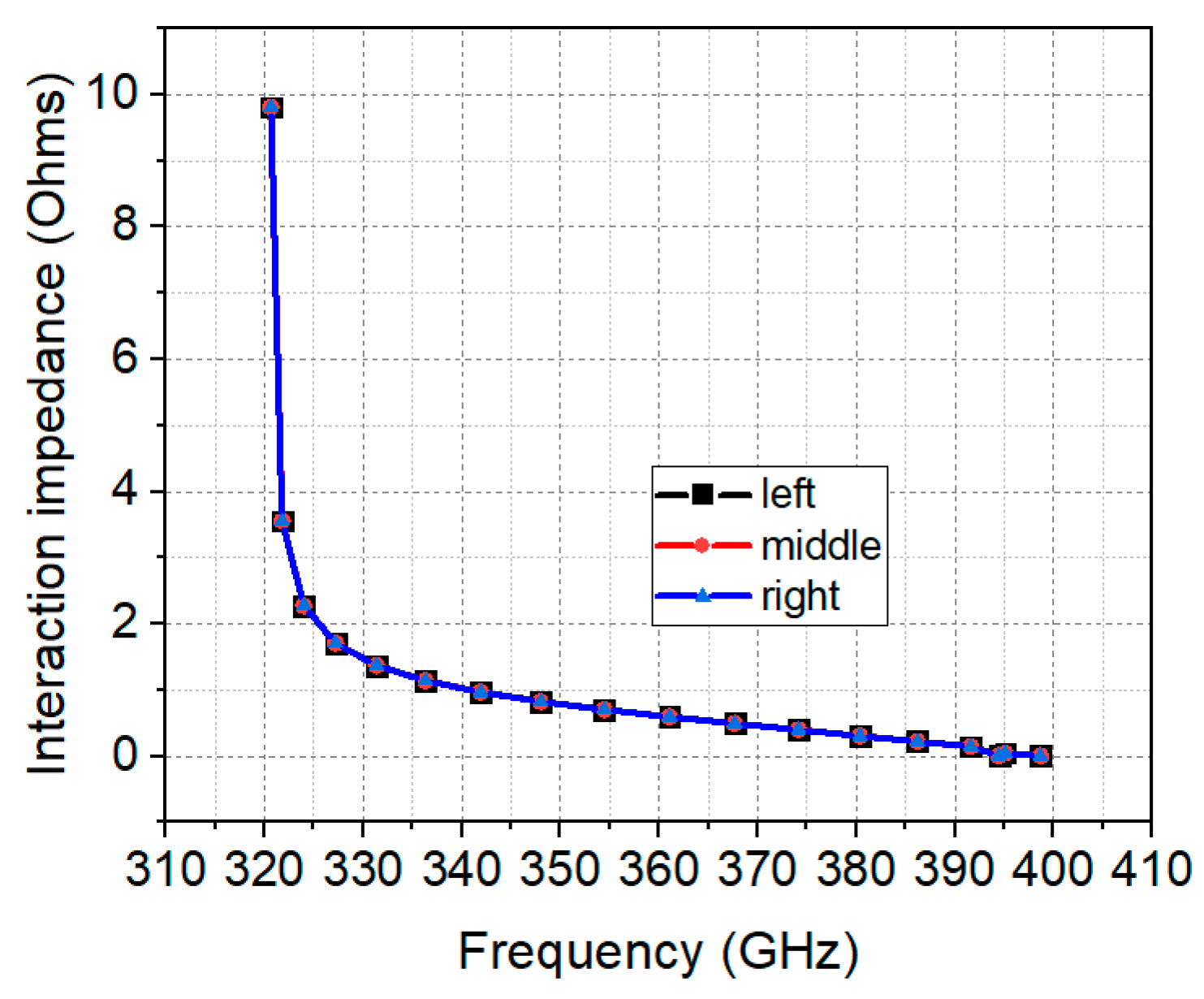
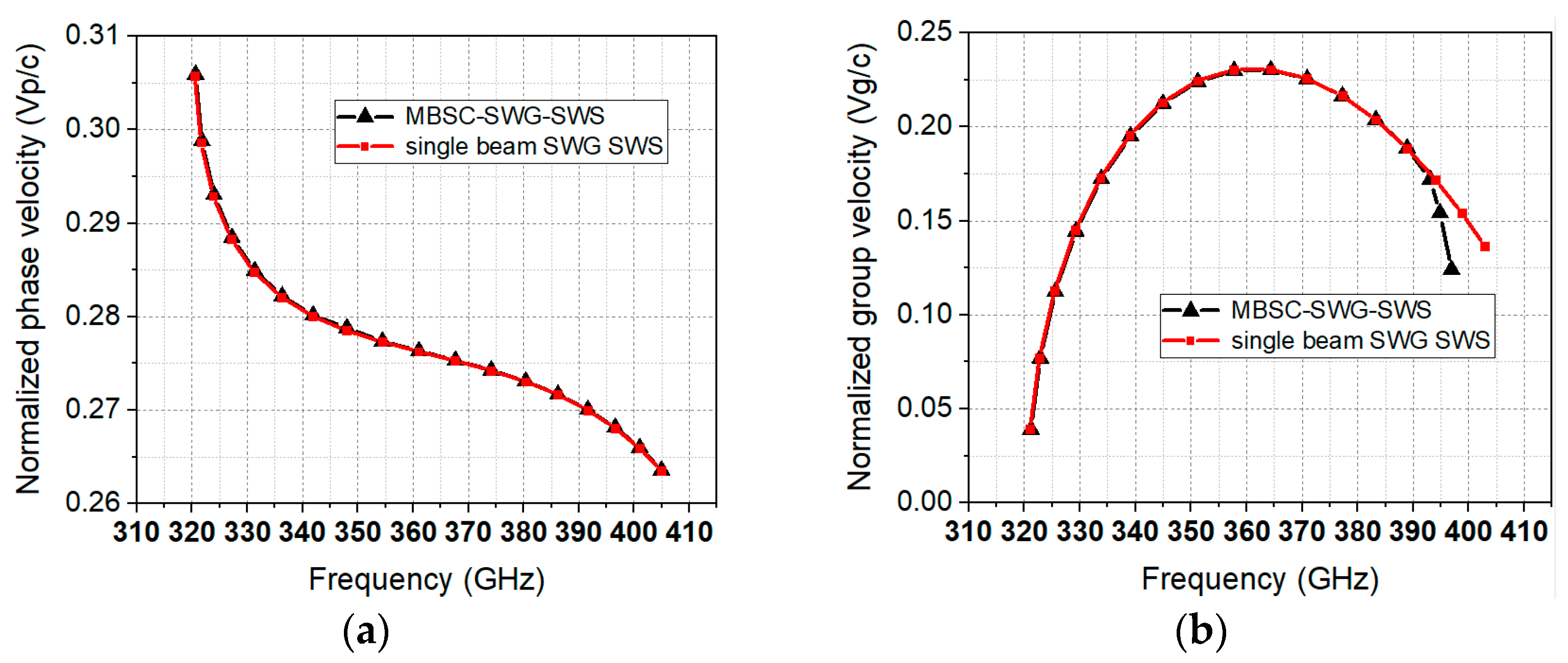
The dispersion characteristics have been calculated using CST software. As shown in Figure 2, all these three modes have a broadband from 315 to 390 GHz. Figure 3 displays the electric field distribution of the MBSC-SWG-SWS. We found that mode three is the best choice for the operation mode in the MBSC-SWG-SWS because the electric field is evenly distributed in all three tunnels. As shown in Figure 4, the interaction impedance at 340 GHz is 1.1 ohm and the interaction impedance of each tunnel is the same. The results in Figure 5 indicate that both the single beam SWG SWS and the MBSC-SWG-SWS have the same phase velocity in the whole band, which means they have the same synchronous voltage. The normalized phase velocity is 0.281 and the normalized group velocity is 0.197 at 340 GHz.

3. Transmission Characteristics

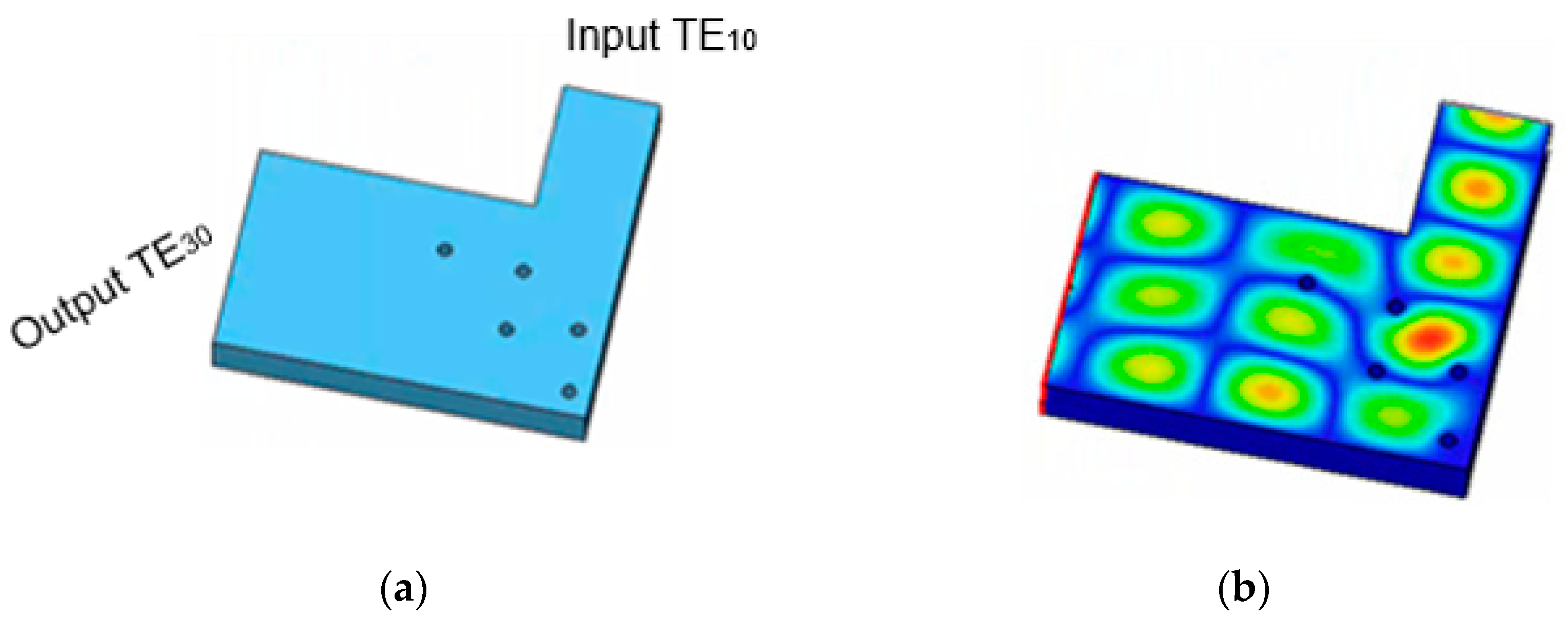
To transfer the TE10 mode in the standard rectangular waveguide WR2 to the TE30 mode in the MBSC-SWG-SWS, a TE10-TE30 mode converter was designed as the input/output structure in the SWS circuit. Figure 6 shows the vacuum model of the converter and the relevant electric field distribution. Five cylindrical metallic columns were used for mode conversion. The simulation results of the mode convertor are presented in Figure 7. The S11 of the mode converter is below −20 dB from 320 to 355 GHz, while the S21 is −0.086 dB at 340 GHz and the associated transfer efficiency is 98%.
As shown in Figure 8, the multi-beam overmoded SWG TWT circuit model, including the SWS circuit, electron beam tunnels and mode converters, was built in the CST STUDIO SUITE. The period number of the main SWS circuit is 120. The equivalent conductivity σ0 can be calculated from the following equations:
σ 0 = σ ( 1 + 2 π arctan ( 1.4 ( R δ ) 2 ) ) 2
δ = 2 ω μ σ
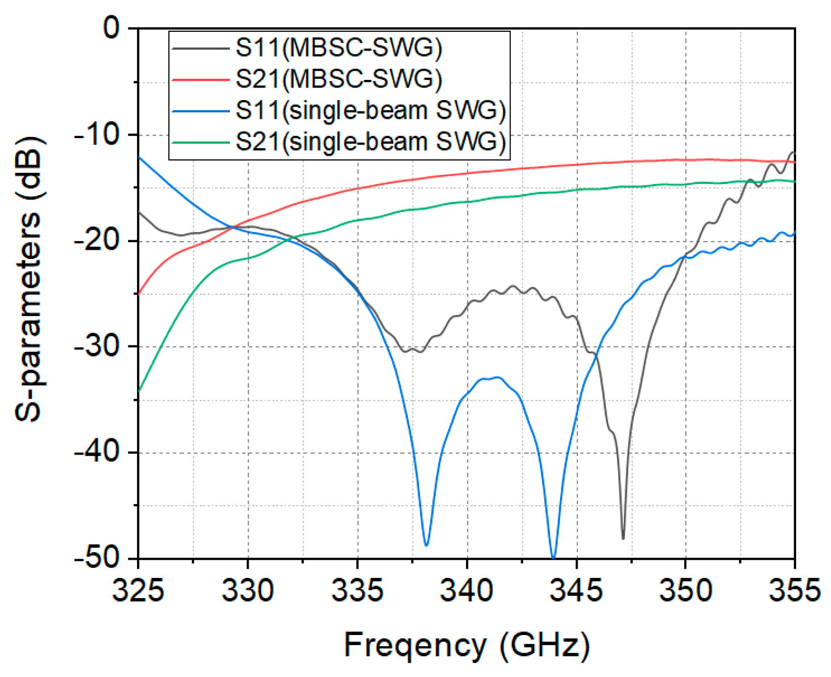
where R is the surface roughness and σ is the conductivity of high conductivity oxygen-free copper. As the surface roughness of the nano-computer numerical control machined model is about 100 nm [17], the effective conductivity is set to 2 × 10 7 s/m. The transmission characteristic is exhibited in Figure 9. The simulation results show that the S11 of the MBSC-SWG-SWS is below –20 dB ranging from 330 to 350 GHz and the S21 is −13.5 dB at 340 GHz, while the S21 of the single beam SWG SWS is −16.3 dB. We found that the loss of the MBSC-SWG-SWS is smaller than that of the single-beam SWG SWS, which is due to the fact that the MBSC-SWG-SWS has a lower power density than the single beam SWG SWS.

4. Beam–Wave Interaction

The beam–wave interaction process for the multi-beam overmoded SWG TWT and the single beam SWG TWT were simulated and are compared in this section. Figure 10 shows the models that consisted of 120 periods. According to the aforementioned Brillouin curve of the MBSC-SWG-SWS, the synchronous voltage is 21.3 kV. To study the output power and gain of the multi-beam overmoded SWG TWT, input signals with frequencies between 332 and 350 GHz, an input power of 0.2 W and an operating current of 54 mA were injected in the waveguide port of the amplifier. A uniform magnetic field of 0.7 T was used to focus the electron beams. Researchers have reported studies of the multi-beam electron optics system that indicate that the generation and the focusing of electron beams can be realized [18,19]. The cross-sectional size of each sheet beam was set to 0.3 mm × 0.06 mm, and the filling ratio was 35.9%. The number of mesh cells was set at 29,096,144. The corresponding maximum and minimum mesh steps were 0.017 and 0.008 mm, respectively. The number of macro particles was fixed at 150, and the time step was 0.003 ns.
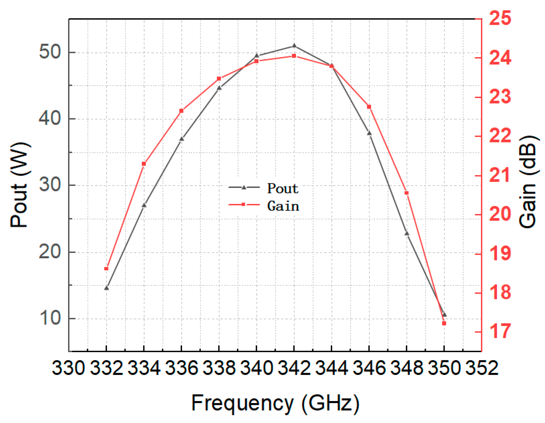
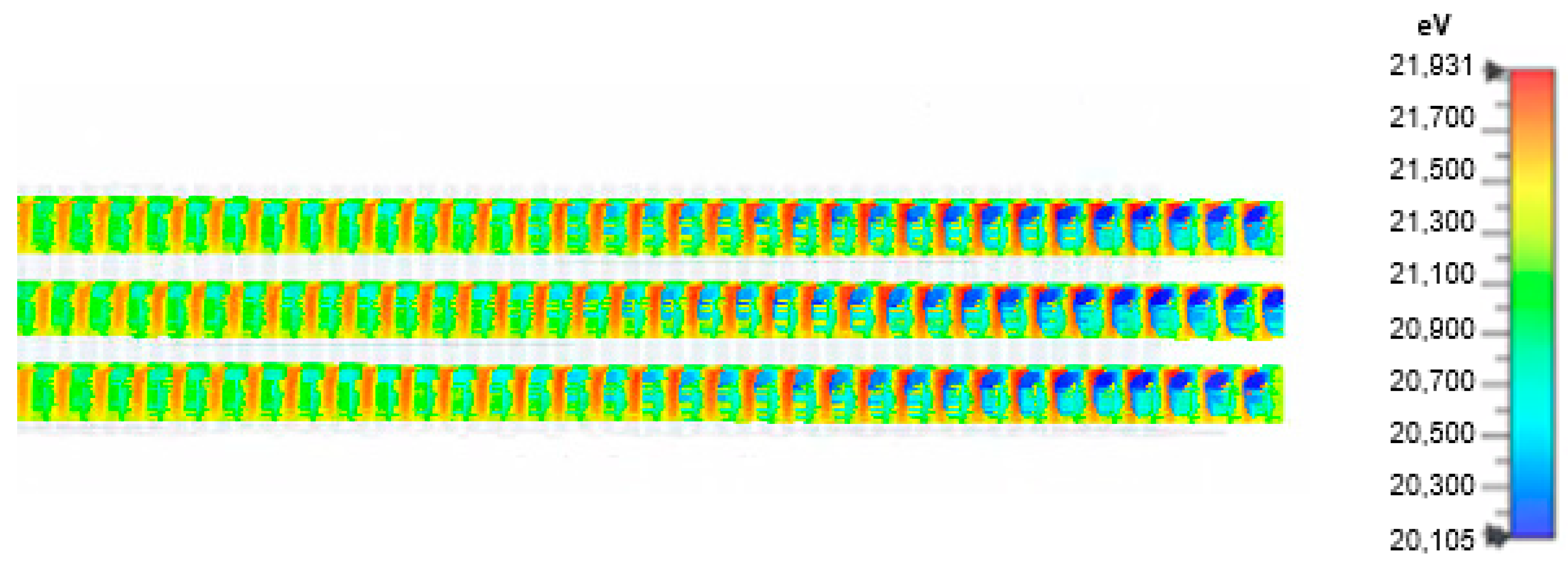
Figure 11 depicts the output power and gain of the multi-beam overmoded SWG TWT versus the operating frequency, respectively. We found that more than 30 W of the output power can be produced from 334 to 347 GHz. The maximum output power is 50 W at 342 GHz and the corresponding gain is 24 dB. Figure 12a gives the time-domain simulation results of the output signal of the multi-beam TWT at 340 GHz, which indicates that the signal is stable after 0.8 ns with a voltage amplitude of 10 V. The potential reflected wave and higher harmonic wave are effectively suppressed, as demonstrated in Figure 12b. The electron bunching effect at the end of the circuit is presented in Figure 13, which illustrates an effective interaction between the electron beams and the electromagnetic wave.
Figure 14a shows the output power versus input power with the operating current of 36 mA (current density is 200 A/cm2) at 340 GHz. For the single beam SWG TWT, the saturated output power can reach 10 W when the input power is 0.1 W. Nevertheless, the saturated output power of the multi-beam overmoded SWG TWT is 30 W when the input power is 0.3 W. If the operating current is 54 mA (current density is 300 A/cm2), as shown in Figure 14b, the saturated output power of the single beam SWG TWT can reach 17 W when the input power is 0.2 W, and the saturated output power of the multi-beam overmoded SWG TWT is 50 W when the input power is 0.3 W. We found that the output power of the multi-beam overmoded SWG TWT is three times that of the single beam SWG TWT.

5. Conclusions

In this paper, an MBSC-SWG-SWS has been proposed to reduce the effect of the phase shift caused by machining errors of independent slow wave circuits, because the energy of each slow wave circuit can be coupled with that of the other circuits. We found that the SWS works in the high order mode through the analysis of its high frequency characteristics; therefore, a TE10-TE30 mode convertor has been designed as the input/output couplers. The study of a multi-beam overmoded SWG TWT based on the MBSC-SWG-SWS shows that an output power of more than 30 W can be obtained in the frequency range from 334 to 346 GHz, and the maximum power and the corresponding gain are 51 W and 24 dB at 342 GHz, respectively. Compared with the single beam SWG TWT, the output power of the multi-beam overmoded TWT is three times that of the single beam SWG TWT. These results suggest that the MBSC-SWG-SWS has the ability to enhance the output power. Consequently, the SWS is a potential and promising structure for the high-power THz traveling wave amplifier.

Author Contributions

Conceptualization, J.L., J.X. and Y.W.; methodology, J.L. and Y.W.; software, J.L. and P.Y.; validation, J.L., J.X. and Y.W.; formal analysis, R.Y., L.Y. and L.X.; investigation, R.Y., Z.W. and W.L.; resources, J.L.; data curation, J.L.; writing—original draft preparation, J.L.; writing—review and editing, J.L., J.X., W.L. and J.F. All authors have read and agreed to the published version of the manuscript.

Funding

This work is support by the National key research and development program of China (Grant No. 2017YFE0130000) and the National Natural Science Foundation of China (Grant No. 61771117).

Conflicts of Interest

The authors declare no conflict of interest.

References

  1. Siegel, P.H. Terahertz technology. IEEE Trans. Microw. Theory Tech. 2002, 50, 910–928. [Google Scholar] [CrossRef]
  2. Sherwin, M. Applied physics: Terahertz power. Nature 2002, 420, 131–133. [Google Scholar] [CrossRef] [PubMed]
  3. Booske, J.H.; Dobbs, R.J.; Joye, C.D.; Kory, C.L.; Neil, G.R.; Park, G.-S.; Park, J.; Temkin, R. Vacuum Electronic High Power Terahertz Sources. IEEE Trans. Terahertz Sci. Technol. 2011, 1, 54–75. [Google Scholar] [CrossRef]
  4. Booske, J.H. Plasma physics and related challenges of millimeterwave-to-terahertz and high power microwave generation. Phys. Plasmas 2008, 15, 055502. [Google Scholar] [CrossRef] [Green Version]
  5. Ding, Y.; Liu, P.; Zhang, Z.; Wang, Y. An Overview of Advances in Vacuum Electronics in China. In Proceedings of the 2011 IEEE International Vacuum Electronics Conference (IVEC), Bangalore, India, 21–24 February 2011. [Google Scholar]
  6. Minenna, D.F.; André, F.; Elskens, Y.; Auboin, J.F.; Doveil, F.; Puech, J.; Duverdier, É. The traveling-wave tube in the history of telecommunication. Eur. Phys. J. H 2019, 44, 1–36. [Google Scholar] [CrossRef] [Green Version]
  7. Xu, X.; Wei, Y.; Shen, F.; Duan, Z.; Gong, Y.; Yin, H.; Wang, W. Sine Waveguide for 0.22-THz Traveling-Wave Tube. IEEE Electron Device Lett. 2011, 32, 1152–1154. [Google Scholar] [CrossRef]
  8. Xie, W.-Q.; Wang, Z.-C.; He, F.; Luo, J.-R.; Liu, Q.-L. Linear analysis of a 0.22THz sine waveguide travelling wave tube. In Proceedings of the 2014 39th International Conference on Infrared, Millimeter, and Terahertz waves (IRMMW-THz), Tucson, AZ, USA, 14–19 September 2014. [Google Scholar]
  9. Fang, S.; Xu, J.; Yin, H.; Lei, X.; Jiang, X.; Yin, P.; Wu, G.; Yang, R.; Li, Q.; Guo, G.; et al. Experimental Verification of the Low Transmission Loss of a Flat-Roofed Sine Waveguide Slow-Wave Structure. IEEE Electron Device Lett. 2019, 40, 808–811. [Google Scholar] [CrossRef]
  10. Yang, R.; Xu, J.; Yin, P.; Wu, G.; Fang, S.; Jiang, X.; Luo, J.; Yue, L.; Yin, H.; Zhao, G.; et al. Study on 1-THz Sine Waveguide Traveling-Wave Tube. IEEE Trans. Electron Devices 2021, 68, 2509–2514. [Google Scholar] [CrossRef]
  11. Cai, K.; Yang, J.; Deng, G.; Yin, Z. Design of 340 GHz Traveling Wave Tube Amplifier Based on Rectangular Staggered Double Vane Slow-Wave Structure. In Proceedings of the 2018 International Conference on Microwave and Millimeter Wave Technology (ICMMT), Chengdu, China, 6–9 May 2018. [Google Scholar]
  12. Hu, P.; Lei, W.; Jiang, Y.; Huang, Y.; Song, R.; Chen, H.; Dong, Y. Development of a 0.32-THz Folded Waveguide Traveling Wave Tube. IEEE Trans. Electron Devices 2018, 65, 2164–2169. [Google Scholar] [CrossRef]
  13. Choi, W.; Lee, I.; Choi, E. Design and Fabrication of a 300 GHz Modified Sine Waveguide Traveling-Wave Tube Using a Nanocomputer Numerical Control Machine. IEEE Trans. Electron Devices 2017, 64, 2955–2962. [Google Scholar] [CrossRef]
  14. Wei, S.; Han-Wen, T.; Zhan-Liang, W.; Tao, T.; Hua-Rong, G.; Zhao-Yun, D.; Yan-Yu, W.; Jin-Jun, F.; Yu-Bin, G. Simulation and cold test of a 340 GHz filleted staggered double vane traveling wave tube. J. Infrared Nfrared Millim. Waves 2019, 38, 303–309. [Google Scholar]
  15. Sheng, L.G.Y.L.M.; Gang, L. Multi-beam TWT with active power combining. Int. J. Electron. 1998, 84, 647–657. [Google Scholar]
  16. Yan, S.; Su, W.; Xu, A.; Wang, Y. Analysis of multi-beam folded waveguide traveling-wave tube for terahertz radiation. J. Electromagn. Waves Appl. 2014, 29, 436–447. [Google Scholar] [CrossRef]
  17. Fang, S.; Xu, J.; Hairong, Y.; Yin, P.; Lei, X.; Wu, G.; Yang, R.; Luo, J.; Yue, L.; Zhao, G.; et al. Design and Cold Test of Flat-Roofed Sine Waveguide Circuit for W-Band Traveling-Wave Tube. IEEE Trans. Plasma Sci. 2020, 48, 4021–4028. [Google Scholar] [CrossRef]
  18. Ruan, C.; Wang, P.; Zhang, H.; Su, Y.; Dai, J.; Ding, Y.; Zhang, Z. Design of planar distributed three beam electron gun with narrow beam separation for W band staggered double vane TWT. Sci. Rep. 2021, 11, 1–12. [Google Scholar] [CrossRef] [PubMed]
  19. Liang, H.; Xue, Q.; Ruan, C.; Feng, J.; Wang, S.; Liu, X.; Zhang, Z. Integrated Planar Three-Beam Electron Optics System for 220-GHz Folded Waveguide TWT. IEEE Trans. Electron Devices 2017, 65, 270–276. [Google Scholar] [CrossRef]
Figure 1. 3D model with sheet beams (red regions). (a) Left view of single beam SWG SWS. (b) Left view of MBSC-SWG-SWS. (c) The cut view of single beam SWG SWS. (d) The cut view of MBSC-SWG-SWS.
Electronics 10 03018 g001
Figure 2. Dispersion curves of MBSC-SWG-SWS.
Electronics 10 03018 g002
Figure 3. Distribution of electric field along the direction of transmission of MBSC-SWG-SWS. (a) Mode 1. (b) Mode 2. (c) Mode 3.
Electronics 10 03018 g003
Figure 4. Interaction impedance of three tunnels for mode 3.
Electronics 10 03018 g004
Figure 5. (a) Normalized phase velocity versus frequency. (b) Normalized group velocity versus frequency.
Electronics 10 03018 g005
Figure 6. (a) Vacuum model of TE10-TE30 convertor. (b) Electric field of TE10-TE30 convertor.
Electronics 10 03018 g006
Figure 7. Simulation results of S-parameters for the TE10-TE30 convertor.
Electronics 10 03018 g007
Figure 8. Vacuum model of TWT circuit using MBSC-SWG-SWS.
Electronics 10 03018 g008
Figure 9. Simulation results of S-parameters for MBSC-SWG-SWS and single-beam SWG SWS.
Electronics 10 03018 g009
Figure 10. Vacuum model for PIC simulation calculation. (a) Single-beam SWG TWT. (b) Multi-beam overmoded SWG TWT.
Electronics 10 03018 g010
Figure 11. The output power and gain of multi-beam overmoded SWG TWT versus the operating frequency.
Electronics 10 03018 g011
Figure 12. (a) Input, output and reflection signals for 340 GHz. (a) Time domain. (b) Frequency spectrum.
Electronics 10 03018 g012
Figure 13. Electrons bunching effect at the end of the circuit.
Electronics 10 03018 g013
Figure 14. The output power versus the input power at 340 GHz. (a) I = 36 mA. (b) I = 54 mA.
Electronics 10 03018 g014
Table 1. Optimized parameters of MBSC-SWG-SWS and SWG SWS.
SymbolValue
MBSC-SWG-SWSSWG SWS
a1.6050.535
b0.380.38
p0.290.29
h0.150.15
d0.040.04
t0.110.11
Publisher’s Note: MDPI stays neutral with regard to jurisdictional claims in published maps and institutional affiliations.